

Page 1
www.transvu.co.uk
Configuration & Operation Guide
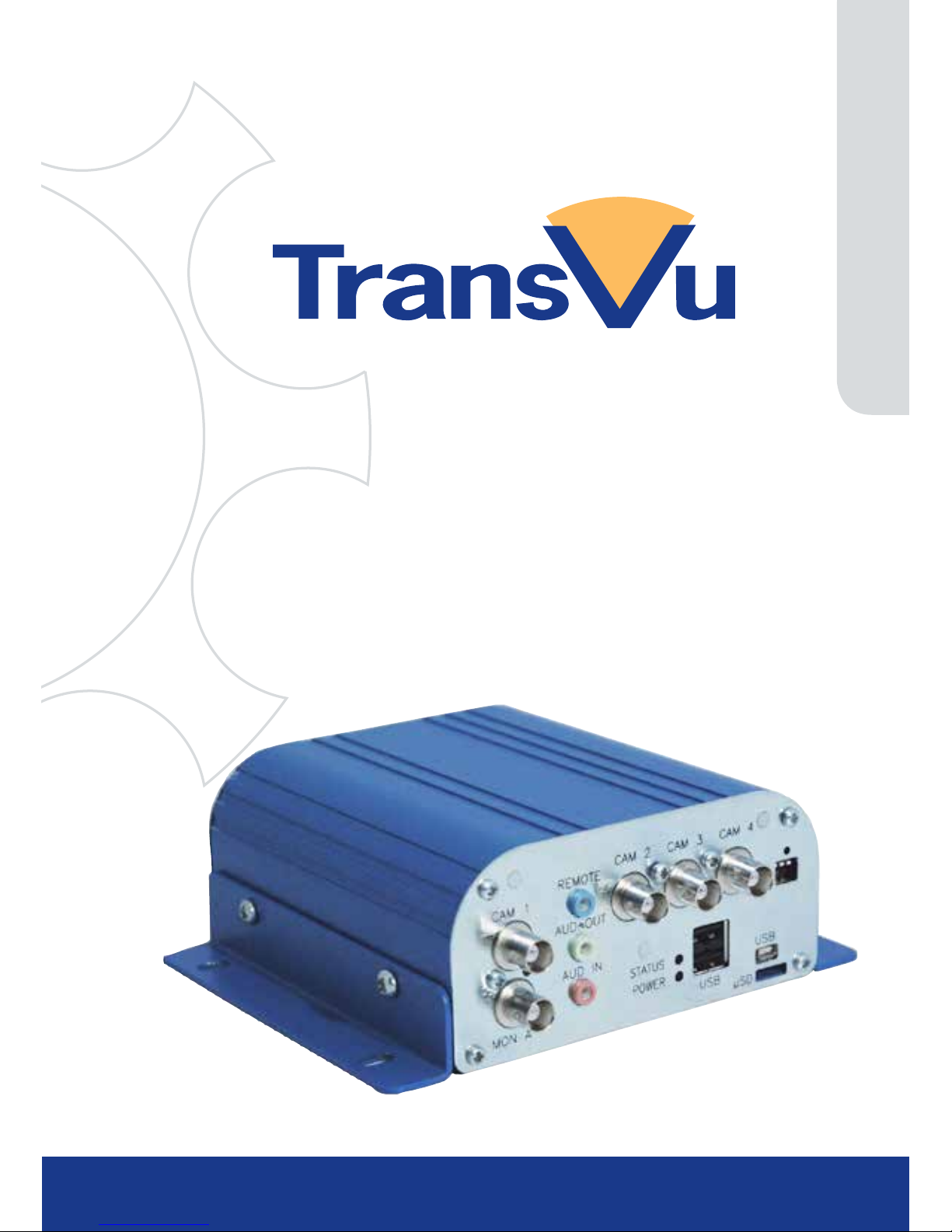
TransVu Compact
Page 2

TransVu Compact
2
Whilst every attempt is made to ensure these manuals are accurate and current, AD Holdings reserve the right to alter
or modify the specication of the machine described herein without prejudice.
Contents
Introduction ............................................. 3
Features .................................................. 4
Important Safeguards .............................. 6
Product Installation .................................. 8
Connections .......................................... 10
Accessing & Conguring the Unit .......... 12
Main Menu ............................................ 14
Navigating The Conguration Menus .... 16
System Settings .................................... 17
Attributes ............................................... 18
Status ................................................... 20
Language .............................................. 25
Time and Date ...................................... 26
Serial Ports ........................................... 27
Power Manager .................................... 28
GPS Settings ......................................... 29
Audio ..................................................... 30
Features ............................................... 31
Maintain ................................................. 36
PowerScript Mgmt ................................. 37
Database ............................................... 38
Console Settings ................................... 39
Viewer Defaults .................................... 40
Display ................................................. 42
Map Cong ............................................ 43
Map Data ............................................... 45
User Accounts ...................................... 46
Camera Settings ................................... 48
Setup ..................................................... 49
Overview ............................................... 54
IP Stream Inputs ................................... 55
Record Settings ..................................... 56
Default ................................................... 57
Prole Record .......................................... 58
JPEG Pre Trigger ...................................... 62
Protect Video ........................................ 63
AoE Setup ............................................. 64
Schedule ............................................... 65
Setup ..................................................... 66
RVRC .................................................... 68
Holiday & Weekend ............................... 69
Alarm Settings ....................................... 70
Inputs ........................................................ 71
Zone Input ................................................. 73
Zone Actions ......................................... 75
Masked Cam Det .................................. 77
Data Logging ......................................... 79
Accelerometer ....................................... 80
Alarm Response Setup ......................... 82
Activity Setup ........................................ 84
VMD Conguration ................................ 86
Global Actions ....................................... 88
Network Settings ................................... 89
Network ................................................. 90
Live Trans .............................................. 91
Multicast Setup ...................................... 93
E Mail .................................................... 95
Remote Reporting ................................. 97
Web Cam .............................................. 99
FTP Download .................................... 100
Firewall ................................................ 102
Features & Text ................................... 103
Features .............................................. 104
Text In Image ...................................... 105
Keyword .............................................. 107
Archive ................................................ 108
Diagnostics .......................................... 109
Event Search ........................................110
Operating the Viewer ...........................112
Appendix A .......................................... 133
Appendix B ........................................ 134
Appendix C .......................................... 138
Appendix D ......................................... 139
Page 3

www.transvu.co.uk
Configuration & Operation Guide
3
Introduction
What is the…
TransVu Compact ?
The TransVu Compact is a Digital Video Recorder and network server designed specically for
transport and mobile applications. Rugged solid state design is designed to resist the vibrations
generated within vehicles whilst standard connectors keep installation simple.
In addition to moving vehicle applications TransVu Compact is ideal for mobile surveillance, rapid
deployment and covert operations.
Vehicles – buses, taxis, vans, trains and heavy goods vehicles are ideal candidates for TransVu
Compact.
Rapid Deployment/Mines/High Risk Areas – the 8 to 17 volt supply voltage range and low current
consumption make the TransVu Compact product range ideal for remote CCTV applications, for
example in areas where solar panels with battery backup provides the only option for power, or
recording in mines, mine vehicles or other high risk areas where health and safety issues place
constraints on power supplies.
Part of the NetVu Connected product range, the TransVu Compact is fully network capable and
supports the Internet standard TCP/IP protocol. As the TransVu Compact is a mobile product the unit
can be accessed via wireless LAN or GSM / GPRS / CDPD / UTMS / HSDPA. Supporting up to four
video inputs, two audio channels, three alarm inputs and intelligent power management the TransVu
Compact is a powerful, cost effective transportation recorder.
The TransVu Compact range includes:
• 4 video inputs - removable micro SD Flash card (class 4).
System Documentation
The Installation and Operation of the TransVu Compact are detailed in the manual suite which
consists of:
• Quick Start Guide - Initial steps to get the TransVu Compact up an running to basic
operation.
• Installation Guide - Full instructions to install the TransVu Compact unit.
• Conguration and Operation Guide - Full conguration documentation for the
TransVu Compact.
This Conguration and Operation Guide will be divided into two parts, Initial Programming and
Operation.
Page 4

TransVu Compact
4
Features
• Developed specically for transport applications
• Ruggedised design
• Simultaneous H264, MPEG-4 and JPEG transmission and recording
• MultiMode Recording - Dynamically-switchable resolution, record-rate &
compression (H264/MPEG4/JPEG) per camera
• Global frame rate of 50pps PAL/60pps NTSC at 2CIF
• Intelligent power management based on ignition and supply voltage sense
• Monitor output provides main monitor functionality via Composite or VGA monitor,
with IR (Infrared Remote) and USB mouse Control
• Web pages provide easy remote conguration
• Accelerometer providing G-force measurements
• Two audio inputs, bidirectional audio support inc Audio Challenge
•
Three BS8418 alarm inputs, Two audio outputs, one relay output, Tacho & Ignition input
• Easy to use on-screen, colour coded softkeys
• Single and Multiway displays on Composite or VGA monitor
• Wake on Alarm Support Via Alarm Input 1
• Serial Telemetry Support via RS422/485 (Com 2)
• Live and playback viewing locally and over Ethernet
•
Full GPS support Via External Module or Ethernet Router, location tracking via GPS
• Wake on GPS Functionality
• Built in activity detection
• Storage on microSD Card, Ethernet storage or USB drive
The unit has NetVu Connected technology built-in to ensure maximum compatibility with future
developments in networked security. NetVu Connected technology enables the Unit to fully interact
with other NetVu Connected compatible products from Dedicated Micros including the DV-IP
Decoder, NetVu ObserVer and PDA Viewers. Providing interoperability between the worlds leading
security companies, NetVu Connected uses industry standard networking protocols supported by a
wide range of third party integration products and SDKs to ensure future on-going compatibility.
COMMON CONFIGURATION INTERFACE
A Common Conguration interface is displayed when the unit’s conguration screens are accessed
locally at the unit or remotely via a web browser. This unied system ensures that the installer is
familiar with the conguration screens irrespective of their location to the unit, minimising training
and familiarisation time and increasing the speed of installation and alteration.
The Unit includes a unique colour-coded menu structure and onscreen Graphical User Interface
(GUI). Context sensitive, the menu structure always represents the area of the menu the user is in,
allowing them to quickly select the options and settings they need without having to trawl through
menu pages and options. The colour coded buttons displayed on the monitor match those on the
touch screen front panel and IR Remote Control, whilst control can also be conducted through an
attached USB Mouse.
Page 5

www.transvu.co.uk
Configuration & Operation Guide
5
Point&go provides the user with easy to use, fast, accurate telemetry control via an attached
monitor. With no need for a telemetry keyboard, users are able to use Pan & Tilt control of a
Dedicated Micros Oracle Dome simply by clicking an area of the monitor. The camera will instantly
respond, positioning the selected area in the middle of the screen, ideal for tracking movement
through a scene.
MAP
Users can now navigate around their CCTV installation using a graphical map. Selecting the
relevant camera from the map will instantly connect the user to that cameras image stream. With the
ability to load bespoke map images and oor plans to reect their installations, the Maps feature is
ideal for quickly identifying camera locations around a site or CCTV network.
Page 6

TransVu Compact
6
Important Safeguards
Read Instructions
All the safety and operating instructions should be read before the unit is operated.
Power Sources
This unit should be operated only from the type of power source indicated on the manufacturer’s
label.
Servicing
Do not attempt to service this unit yourself as opening or removing covers may expose you to
dangerous voltage or other hazards.
Refer all servicing to qualied service personnel.
Ventilation
Ensure unit is properly ventilated to protect from overheating.
All the safety and operating instructions should be read before the unit is operated.
To prevent re or shock hazard, do not expose this equipment to rain or moisture. The lightning ash
with arrowhead symbol within an equilateral triangle is intended to alert the user of this equipment
that there are dangerous voltages within the enclosure which may be of sufcient magnitude to
constitute a risk of electric shock.
This is a class A product. In a domestic environment this product may cause radio interference in
which case the user may be required to take adequate measures.
Lightning Strike
The unit has some in-built protection for lightning strike, however it is recommended that isolation
transformers be tted to the system in areas where lightning is a common occurrence.
Regulatory Notes and FCC and DOC Information
(USA and Canadian Models Only)
Warning: This equipment has been tested and found to comply with the limits for a Class A digital
device, pursuant to part 15 of the FCC rules. These limits are designed to provide reasonable
protection against harmful interference when the equipment is operated in a commercial
environment. This equipment generates, uses, and can radiate radio frequency energy and, if not
installed and used in accordance with the instruction manual, may cause harmful interference to
radio communications. Operation of this equipment in a residential area is likely to cause harmful
interference in which case the user will be required to correct the interference at their own expense.
If necessary, the user should consult the dealer or an experienced radio/television technician for
corrective action. The user may nd the following booklet prepared by the Federal Communications
Commission helpful: “How to Identify and Resolve Radio-TV Interference Problems”.
This booklet is available from the US Government Printing Ofce, Washington, DC20402,
Stock No. 004-000-00345-4.
This reminder is provided to call the CCTV system installer’s attention to Art. 820-40 of the NEC that
provides guidelines for proper grounding and, in particular, species that the cable ground shall be
connected to the grounding system of the building, as close to the point of cable entry as practical.
Page 7

www.transvu.co.uk
Configuration & Operation Guide
7
CE Mark
If this product is marked with the CE symbol it indicates compliance with all applicable directives.
Directive 89/336/EEC.
A ‘Declaration of Conformity’ is held at Dedicated Micros Ltd.,
1200 Daresbury Park, Daresbury, Cheshire, WA4 4HS, UK.
Page 8
TransVu Compact
8
Product Installation
The TransVu Compact should be mounted as low as possible within the vehicle, on a secure base
free from resonance and secondary vibrations.
Installation requirements
Note: Read all the instructions before commencing installation.
Care in feeding cables
Ensure the cables are clamped to the same mounting surface as the TransVu Compact. This will
help avoid any vibration being transmitted along them to the unit.
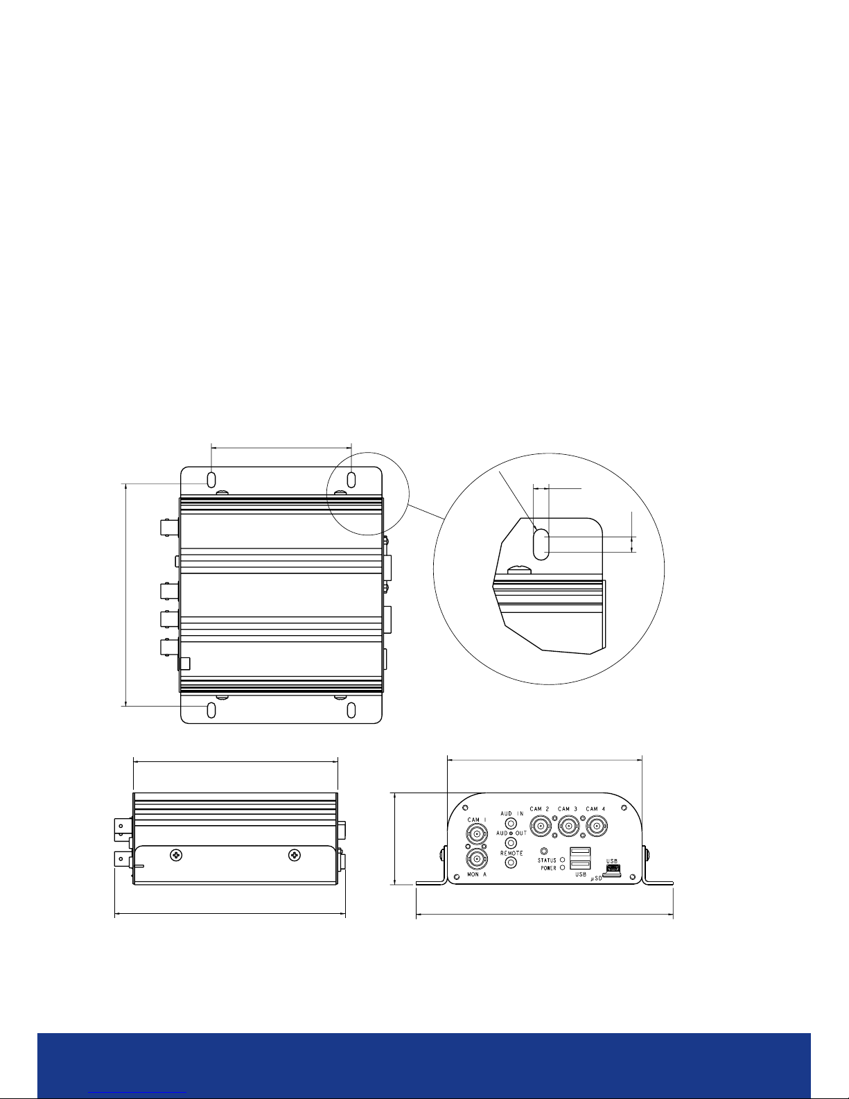
Recommended tment area - 285mm (11¼”) x 195mm (7¾ “)
Minimum height of enclosure - 90mm (3½ “)
Notes on installation space
Additional space is required around the electrical connectors to allow the disconnection of the cables
from the unit.
The unit does not require alignment with the normal direction of travel of the vehicle.
TransVu Compact dimensions
143
90
5
5
2.5
131.4
148
125
165
59
Page 9

www.transvu.co.uk
Configuration & Operation Guide
9
Front Panel
Description Function
SERIAL RS232 port which defaults to the debug function
VGA VGA output to allow connection of spot monitor (using this connection will
disable the MON A output)
PWR IN & IGN +12V OUT 12V fused input from battery (refer to Connections) & 12V output to support
ancillary equipment (refer to Connections)
GPS Standard RJ12 socket for connection to approved GPS unit
ALARMS/RELAY 9 way (female) D Type 24V 200mA
3 General Alarm Inputs/BS8414 EOL Alarms
1 Onboard light duty relay output (500mA@12V-48V Max)
NET1 RJ45 Ethernet network connector, 10/100 Mb/s Ethernet Network
NET0 RJ45 Ethernet network connector, 10/100 Mb/s Ethernet Network
Rear Panel
Description Function
CAM 1 - 4 75Ω BNC composite video inputs 1V pk-pk
MON A 75Ω BNC composite monitor output, 1V pk-pk
STEREO AUD IN 3.5mm phono socket, 8KHz/16KHz/22KHz sampling 75Ω input impedance, 1V
pk-pk
STEREO AUD OUT 3.5mm (phono) socket, line level <100Ω output impedance,1V pk-pk
amplication required
REMOTE 3.5mm socket for Remote IR extender (supplied)
STATUS LED Illuminates red until the unit senses a failure condition
POWER LED Illuminates red when the unit has power applied
USB 2x USB2.0 connectors
USB 1x Micro USB connector
μSD Socket for micro SD storage card (minimum class 4)
Page 10
TransVu Compact
10
Connections
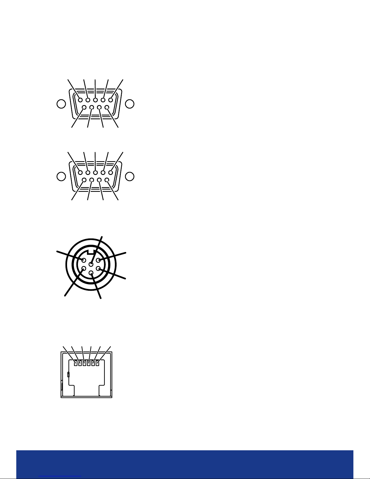
The TransVu Compact features the following connectors, all views are shown looking at the
connectors on the rear of the unit
54321
9876
SERIAL 1 DCD (COM2 RS485+)
2 RXD
3 TXD
4 DTR (COM2 RS422-)
5 GND
6 DSR (COM2 RS422+)
7 RTS
8 CTS
9 RI (COM2 RS485-)
12345
6789
ALARMS/RELAY 1 RELAY 1 (A)
2 RELAY 1 (B)
3 TACHO IN
4 Digital GND
5 Ignition
6 ALM1 (wake on alarm)
7 ALM2
8 ALM3
9 Digital GND
PWR IN
1 DC Input +
IGN 2 Ignition
+12V OUT 3 DC Ground
4 Alarm
5 Aux Ground
6 Aux Power Out
GPS
Pin Conn Description
1 N/A No connection
2 DGND Digital ground
3 AT_RXD ATMega88 GPS receive data (RS232)
4 AT_TXD ATMega88 GPS transmit data (RS232)
5 +5V +5V GPS feed
6 N/A No connection
6 5 4 3 2 1
6
5
4
3
2
1
PWR IN
IGN
+12V OUT
Page 11
www.transvu.co.uk
Configuration & Operation Guide
11
Addendum
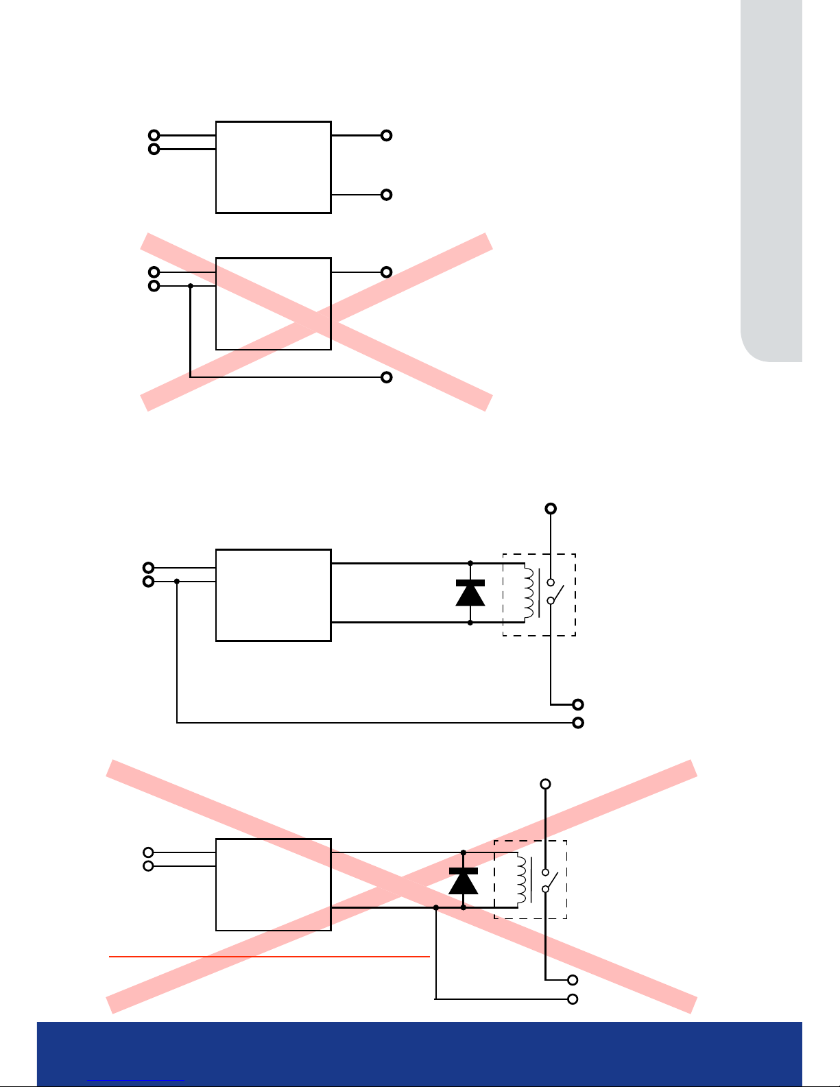
AUX CURRENT UP TO A MAXIMUM OF 1A SWITCHING CASE
Aux GND
+ve To cameras & low power equipment (MAX 1Amp)
GROUND POWERED DEVICE THROUGH DVR
TransVU Compact
Aux Power Out
Aux GND
DC Input +
DC Ground
DC Input +
DC Ground
Aux GND
+ve To cameras & low power equipment
DO NOT GROUND POWERED DEVICE THROUGH PSU
TransVU Compact
DC Input +
DC Ground
DC Input +
DC Ground
Aux Power Out
AUX CURRENT GREATHER THAN 1A SWITCHING CASE
High Current +ve
+ve To cameras, illuminators etc
GND output
RELAY
TransVU Compact
DC Input +
DC Ground
DC Input +
DC Ground
Aux Power Out
Aux GND
High Current +ve
Aux GND
+ve To cameras, illuminators etc
RELAY
TransVU Compact
DC Input +
DC Ground
DC Input +
DC Ground
Aux Power Out
Aux GND
DO NOT GROUND HIGH POWERED DEVICES THROUGH DVR
Page 12

TransVu Compact
12
Accessing & Conguring the Unit
The unit can be congured either on the local monitor or over the network using a PC with Internet
Explorer or similar browser. Both have near identical menu interfaces.
Accessing the menus on a local monitor
The Conguration pages can be displayed on a local monitor (refer to ‘Installing The Unit’ for
guidance on connecting a local monitor). When a monitor is successfully connected, use a
USB mouse and move the pointer to the bottom of the screen. The navigation colour bar will be
displayed. Select ‘Next’ until the ‘Menu’ option is displayed. When ‘Menu’ has been selected, the
unit’s Conguration pages will be displayed.
Accessing the menus on a PC web browser
Locating the Unit IP address
The IP address of the unit is required to access the webpages. It can be identied from the
conguration menu pages using the local monitor. Follow the procedure detailed above and navigate
to the Conguration Menu:System Settings->System menu to nd the DHCP assigned IP address.
Note: The unit can be installed in a DHCP network environment where an IP address, subnet mask and
default gateway will automatically be allocated from the network DHCP Server (DHCP is enabled
by default).
Note: If a DNS (Domain Name Server) address is not to be used, it is strongly advised that a xed IP
address be assigned (a DHCP assigned address can change without notication i.e. following
power failure).
A xed IP address can be assigned via the Conguration Menu:Network Settings
->Network menu.
Default DNS Address
It is recommended that a DNS (Domain Name Server) address be congured. Assigning a
recognisable name can help a remote user to locate the unit.
If no System name is allocated to the unit, the default DNS address will be:
machine serial number.yourdomain.com
• <machine serial number> is displayed in the System menu page and also on
the underside of the unit.
• <yourdomain> is the name assigned to your DNS network.
The default DNS address can be renamed via the Network Settings->Network menu. Following
renaming, the DNS address will be:
yourname.yourdomain.com
• ’ yourname‘ is the name assigned via the Network menu.
• <yourdomain> is the name assigned to your DNS network
Note: To activate an assigned DNS address, it will be necessary to reboot the unit. The unit can be
rebooted via System Settings:>Maintain-> Reset.
IMPORTANT: To set the time and date on the unit, navigate to System Settings
->Time and Date.
Page 13

www.transvu.co.uk
Configuration & Operation Guide
13
Accessing the Conguration Webpages
The unit can be congured using the webpages. To access these:
1. Launch Internet Explorer (or similar web browser package).
2. Type the URL for the unit (IP or DNS address).
3. The Opening menu page will be displayed.
.
Page 14
TransVu Compact
14
Main Menu
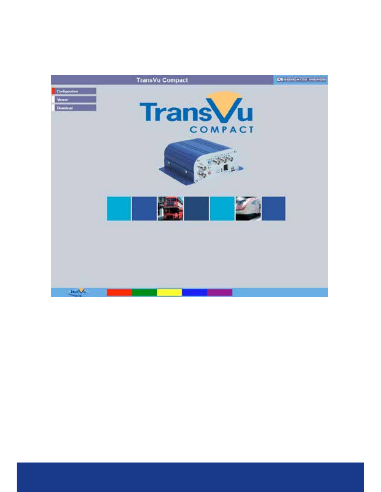
When rst accessing the unit, the main menu will be displayed. This menu allows access to the
Conguration menus, the Viewer menus and also several Download options.
Note: The Download options will only be available if viewing remotely via an IP connection.
Select the Conguration menu tab to access the unit’s Conguration menus. Refer to ‘Navigating the
Conguration Menus’ for further guidance.
Select the Event Search tab to access the unit’s Event Search function. Refer to ‘Event Search’ for
further guidance.
Note: The ‘Event Search’ option will only be displayed if ‘Enable Event Search’ is selected in the
‘Features’ menu: System Settings->Features.
Select the Viewer menu tab to access the unit’s Viewer function. Refer to ‘Unit Operation’ for
information on the numerous Viewer features.
Select the Download menu tab to access the various Download sub-options. Select from:
• Product Manual Select to open an electronic version of the
Installation & Operation Guide.
• ObserVer Manual Select to open an electronic version of the NetVu ObserVer
User Guide. NetVu ObserVer is a free video management
software package from AD. It allows users to seamlessly
view distributed images from any ‘NetVu Connected’ product.
• NetVu ObserVer Select to download the NetVu ObserVer video
management software.
• Java (JRE) Select to download the Java (JRE) software (from the unit).
This software is required to successfully view Conguration
and Viewer menus remotely.
Page 15

www.transvu.co.uk
Configuration & Operation Guide
15
IMPORTANT: By default, no Usernames and Passwords are required to access any of the
various menus. Usernames and Passwords can however be added to regulate
access to the Conguration and Viewer menus. Refer to the ‘Display Settings->
User Accounts’ menu for information on establishing Usernames and Passwords.
Page 16
TransVu Compact
16
Navigating The Conguration Menus
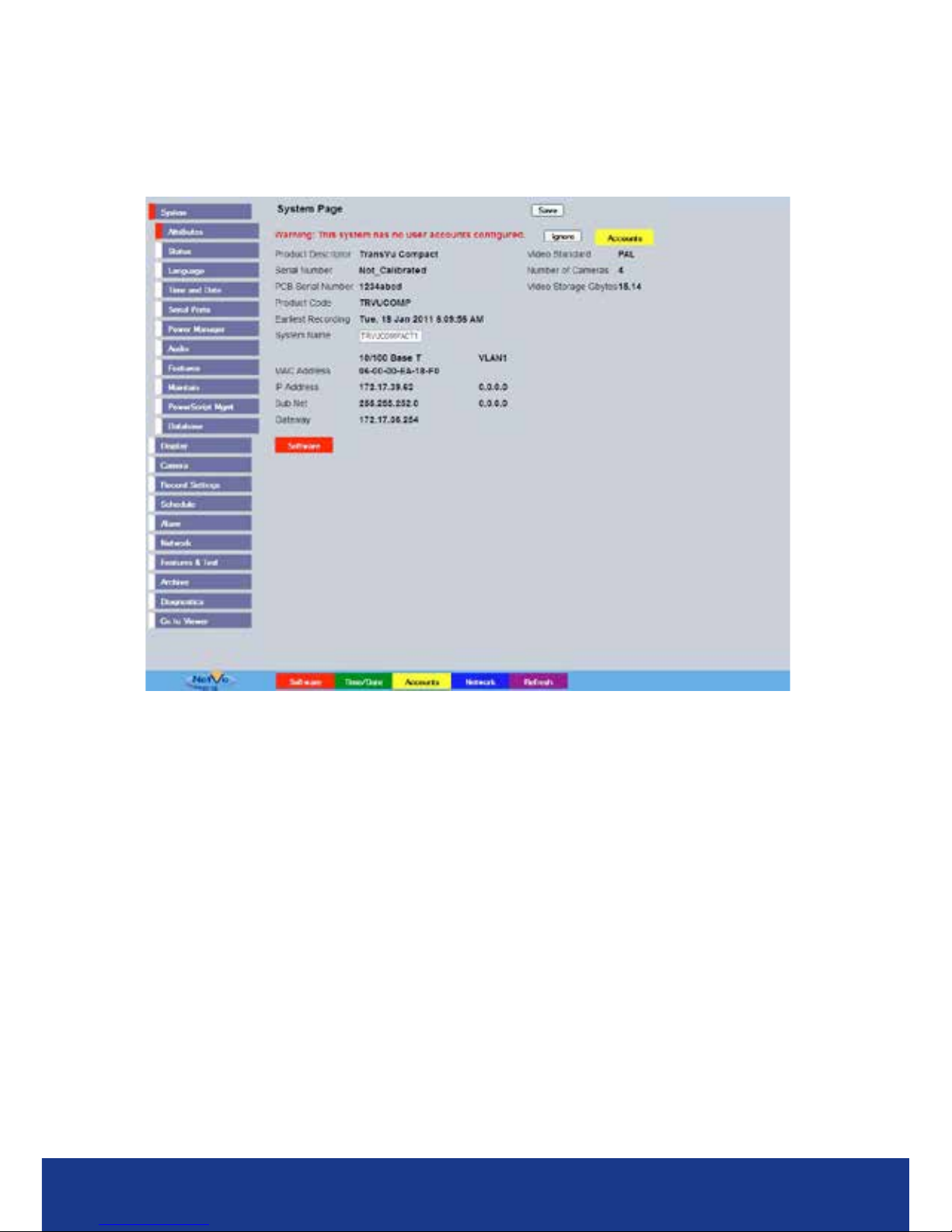
When accessing the conguration menus, the menu tree will be displayed.
The conguration pages are navigated using the menu tree (displayed on the left of each page).
Selecting one of the menu options will display the relevant page. Associated sub-menus will then be
available.
Relevant menus can also be accessed directly from other menu screens via the coloured softkey
options shown at the base of each menu. The options available will depend on the menu being
viewed. Select a softkey option by pressing either the corresponding button on the IR Remote
Control (if viewing the menus locally), or by selecting the relevant option via the PC mouse (if
viewing the webpages).
Note: Any changes made via the webpages are automatically saved when the page is closed. To
‘manually’ save changes, select the Save option.
Page 17

www.transvu.co.uk
Configuration & Operation Guide
17
System Settings
The menus under the System Settings heading allow the unit’s core settings to be viewed, changed
and the system software upgraded.
The Attributes option displays details about the unit including the IP address, unit serial number,
MAC address and software version.
The Status page displays information about the unit’s operating condition, shows how long the unit
has been operating and the reason for the last reset. It also shows camera status and displays any
failed cameras.
The Language page allows the system language to be set. The language can also be changed for
the current session only.
The Time and Date page allows the unit time and date settings to be adjusted, including setting
the timezone.
The Serial Ports page allows each of the two serial ports to be individually congured for one of a
range of operations, including, debug, PPP and telemetry.
The Power Manager page allows the conguration of power saving procedures such as the timeout
limits for ignition off and low voltage level detected.
The Audio page shows the settings available for each of the audio channels and allows conguration
of audio quality.
The Features page allows control of the different features that are available within the software
including Email reporting, webcam support and control of the display resolution.
The Maintain page allows the current conguration to be saved, and for previously saved settings to
be loaded. It also enables easy upgrade of the system software.
The PowerScript Mgmt page allows installed PowerScripts to be activated/deactivated on start-up.
The Database page allows the database to be reset, and can be used to limit the number of entries
held in it.
Page 18
TransVu Compact
18
Attributes
6.13
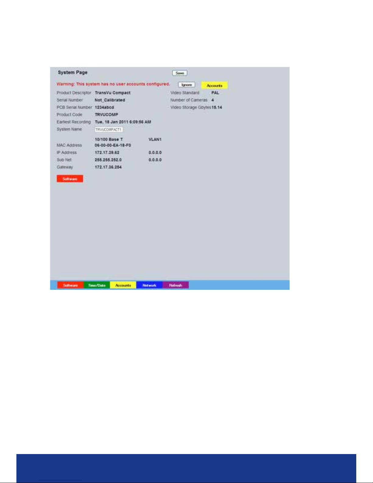
This menu shows the general information about the unit including the version of software installed,
the unit’s serial number and the allocated DHCP IP address.
Product Descriptor Details the product model.
Serial Number Identies the serial number of the specic unit.
PCB Serial Number Displays the PCB (Printed Circuit Board) serial number of the unit.
Product Code Displays a code identifying the unit’s specication.
Earliest Recording Displays the date/time of the earliest recording held on the unit.
System Name This eld can be edited to allocate a name to the unit. This is displayed
when the unit is accessed via NetVu ObserVer and is sent when
transmitting information to a Remote Video Response Centres (RVRC).
Video Standard Displays the video standard adopted by the unit i.e. PAL, NTSC.
Number of Cameras Shows the number of camera channels on the unit.
Video Storage Gbytes Highlights the available video storage capacity in Gigabytes.
MAC Address This is the MAC address assigned to the unit.
IP Address
This is the IP address allocated to the unit.
Sub Net This is the subnet of the network where the unit is located.
Gateway This is the IP address of the default gateway (router) assigned by the DHCP
server.
Software (Red) Select this option to display installed software information
(see below).
Page 19
www.transvu.co.uk
Configuration & Operation Guide
19
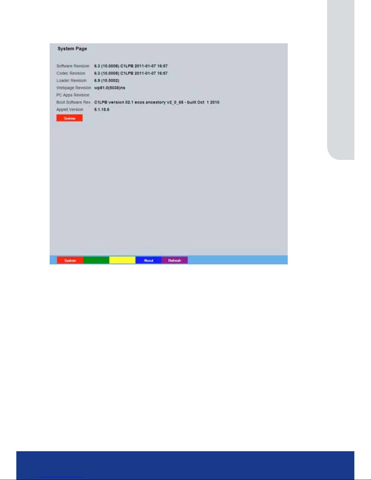
Software Menu
Software Revision This identies the version of software the unit is running.
Codec Revision This identies the codec version the unit is running.
Loader Revision This identies the bootloader version the unit is running.
Webpage Revision This identies the webpage version the unit is running.
PC Apps Revision This identies the revision archive of the Viewer and associated PC Apps
software.
Boot Software Rev. Displays the infrastructure componentry software revision.
Applet version This identies the version of the Java applet installed on the unit.
Page 20

TransVu Compact
20
Status
Unit Status
This menu details information regarding the status of the unit, notably the total time the unit has
been operating and the time since its last reset.
Time since last reset Details the time since the unit was last reset.
Temp This details the current internal temperature (in celsius) of the unit.
Total running time Details the total time the unit has been operational.
Reset code The last reset code used is displayed.
Restart reason The reason for the last restart is displayed i.e. Controlled
User Reset.
Current PPS Displays the current system record rate.
Codecs Details the current number of installed codecs.
Cameras Lists the available camera connections
Connected Camera channels with cameras connected will be highlighted light green. Those
not in use will appear dark green.
Recording Camera channels that are recording will be highlighted light green. Those not in
use will appear dark green.
Cam Status Those camera channels where the connection is deemed to have failed will be
highlighted in red. Those working correctly will appear light green. Those not in
use will appear dark green.
Page 21
www.transvu.co.uk
Configuration & Operation Guide
21
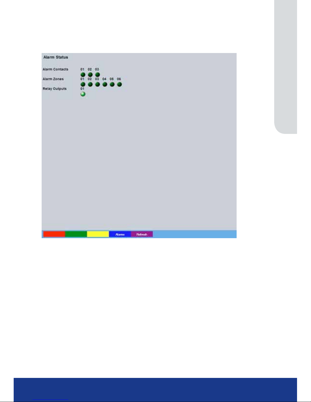
Alarm Status
This menu details information regarding the alarm status of the unit, detailing the status of alarm
Contacts, Zones and the relays Outputs.
Alarm Contacts Details the state of the alarm contacts. Contacts will display dark green when
open/passive, light green when closed/active.
Alarm Zones This details the status of the 6 available alarm zones. Zones will display dark
green when passive, light green when active.
Relay Outputs The relay output will display dark green when open, light green when closed.
Page 22
TransVu Compact
22
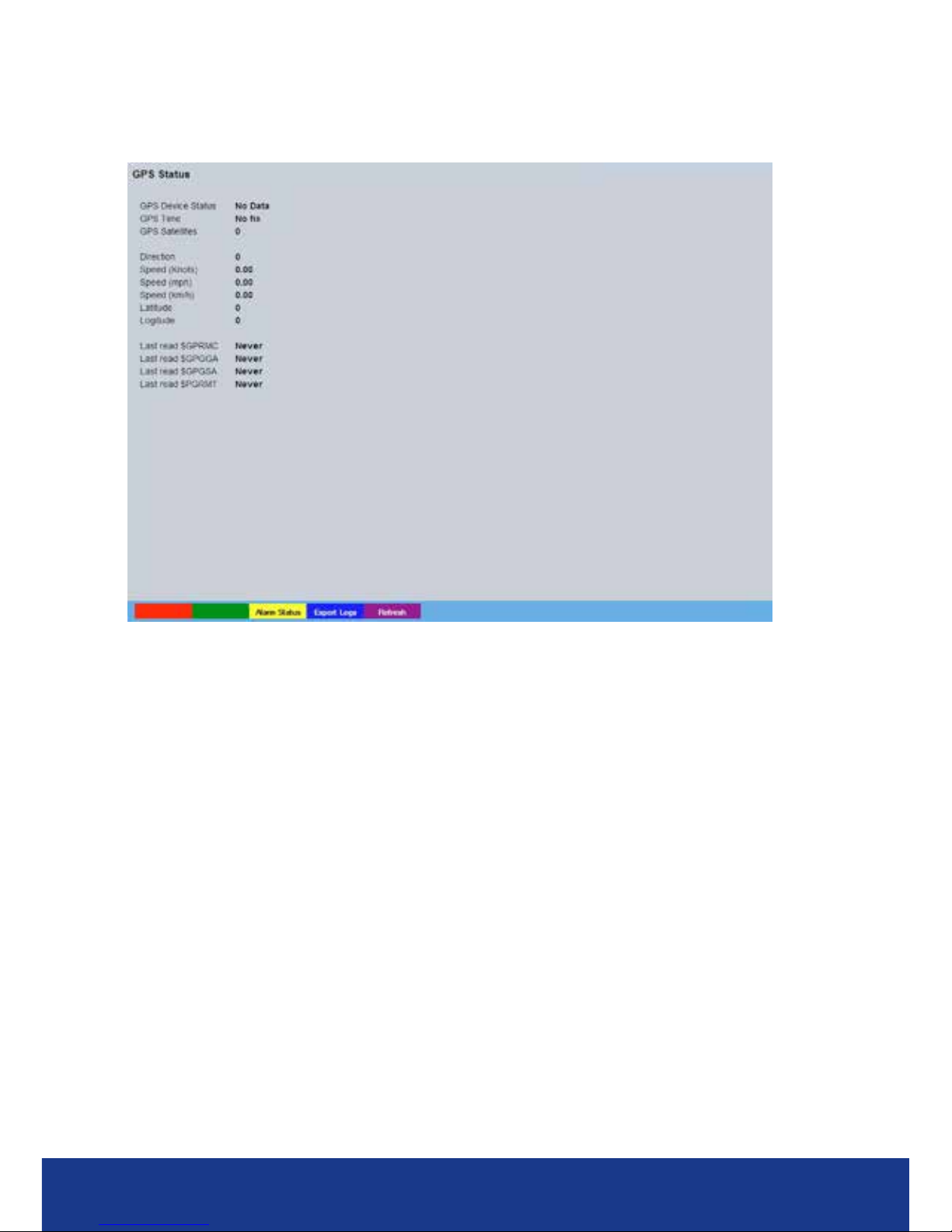
GPS Status
This menu details information regarding the status of the GPS device. It will show GPS information
when any suitable GPS device* is correctly connected and congured.
Device Status Shows the current state of the connection between the unit and the GPS device.
Options are ;
OK Normal operation.
Unhandled Error Can occur if the GPS is enabled and the unit isn’t
rebooted to start up the GPS task.
Satellite Error No satellites are available.
Port Closed The port associated to the GPS failed to open or
closed unexpectedly.
No Data The GPS device is congured correctly on the unit
but the unit has never received any data from the
connected GPS device
Data Timeout This means the GPS was sending data but has
timed out and not sent anything for about ve
seconds or more.
GPS Disabled In theory this should never be shown as the GPS
status page cannot be accessed with the GPS
disabled but if the page is already on screen and
someone disables the GPS this message will
appear.
Bad Data Bad data coming from the GPS device, usually
indicates wrong baud rate.
GPS Time Time registered on GPS unit.
GPS Satellites No of Satellites available to GPS unit.
Direction Direction of unit travel.
Speed (knots) Speed of GPS unit in knots.
Speed (mph) Speed of GPS unit in mph.
Speed (km/h) Speed of GPS unit in kph.
Latitude Latitude read by GPS unit.
Page 23
www.transvu.co.uk
Configuration & Operation Guide
23
Longitude Logitude registered by GPS unit.
The following data statements are standard GPS format responses:
Last Read $GPRMC Details the recommended minimum GPS data.
Last Read $GPGGA Details the Fix information.
Last Read $GPGSA Details the Overall satellite data.
Last Read $PGRMT Details the Sensor status information.
* Any GPS device that outputs the GPRMC string will work with TransVu Compact
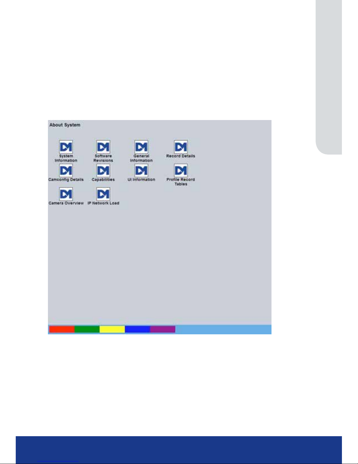
About
This menu allows access to numerous system information pages. Select the an icon to view the
relevant pages, refer to ‘Appendix E - Status Pages’ for a description of each page.
System Information Select to open to the System->Attributes page.
Software Revisions
Select to open to the System Settings->System->Software page.
Page 24
TransVu Compact
24
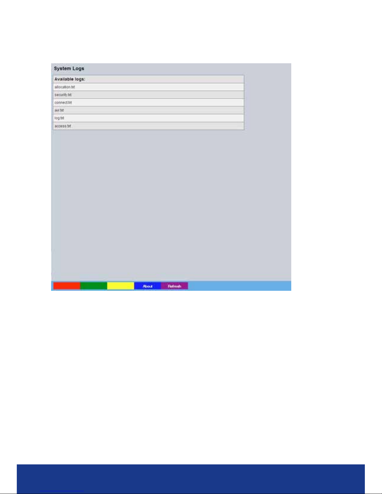
Logs
The log les stored in the unit can be accessed from this page. Selected logs are displayed on the
page below.
About (Blue) Select to open the System->Status->About page.
Refresh (Purple) Refreshes the information on the current page.
Page 25
www.transvu.co.uk
Configuration & Operation Guide
25
Language
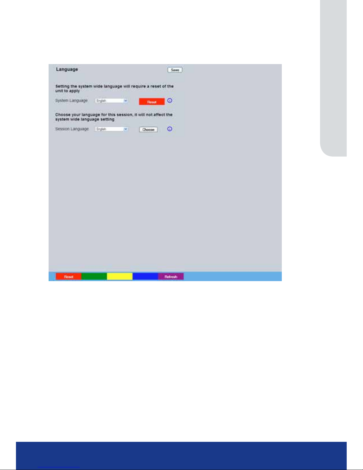
This menu allows the system language to be set. Changing the System Language will effect all
menu pages. If required, the language can also be changed for the current session only.
System Language Select to change the system language setting.
Reset (Red) Select to reset the unit.
Note: The unit MUST be reset to implement system language changes.
Session Language Select to change the language settings for the current session only.
Choose Select to immediately activate session language changes.
Page 26
TransVu Compact
26
Time and Date
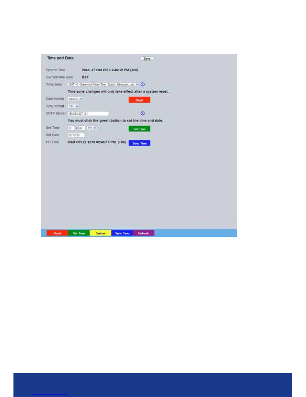
This menu allows the time and date to be set on the unit. Required timezone information can also be
established and the unit time synchronised to that of the PC being used to view the webpages.
System Time The current system time and date is displayed.
Current Time Zone Displays the currently selected time zone settings.
Time Zone
Select the relevant timezone offset from the accompanying drop down menu
.
Reset (Red) When a change has been made to the unit’s Time Zone setting, it is necessary
to reset the unit before the change will take effect.
Date Format
As default, the date is entered dd/mm/yy. It can also be displayed as mm/
dd/yy or yy/mm/dd.
Time Format As default, the time displayed is in 12 hour format. This can be changed to
24 hour if required.
SNTP Server A Simple Network Time Protocol (SNTP) server allows external devices to
connect and set their current date and time settings to that of the SNTP. If
required, enter the SNTP server IP address here.
Set Time Enter a current time for the unit.
Set Date Enter a current date for the unit.
Set Time (Green) When current ti
me/date as been entered, select this button to i
mplement changes.
PC Time Displays the system time of the PC currently being used to view the webpages.
Sync Time (Blue)
Use this button to synchronise the time of the unit to that of the PC being
used to view the webpages.
Note: The PC Time and Sync Time options will only be available if viewing the menu via
the webpages.
Page 27
www.transvu.co.uk
Configuration & Operation Guide
27
Serial Ports
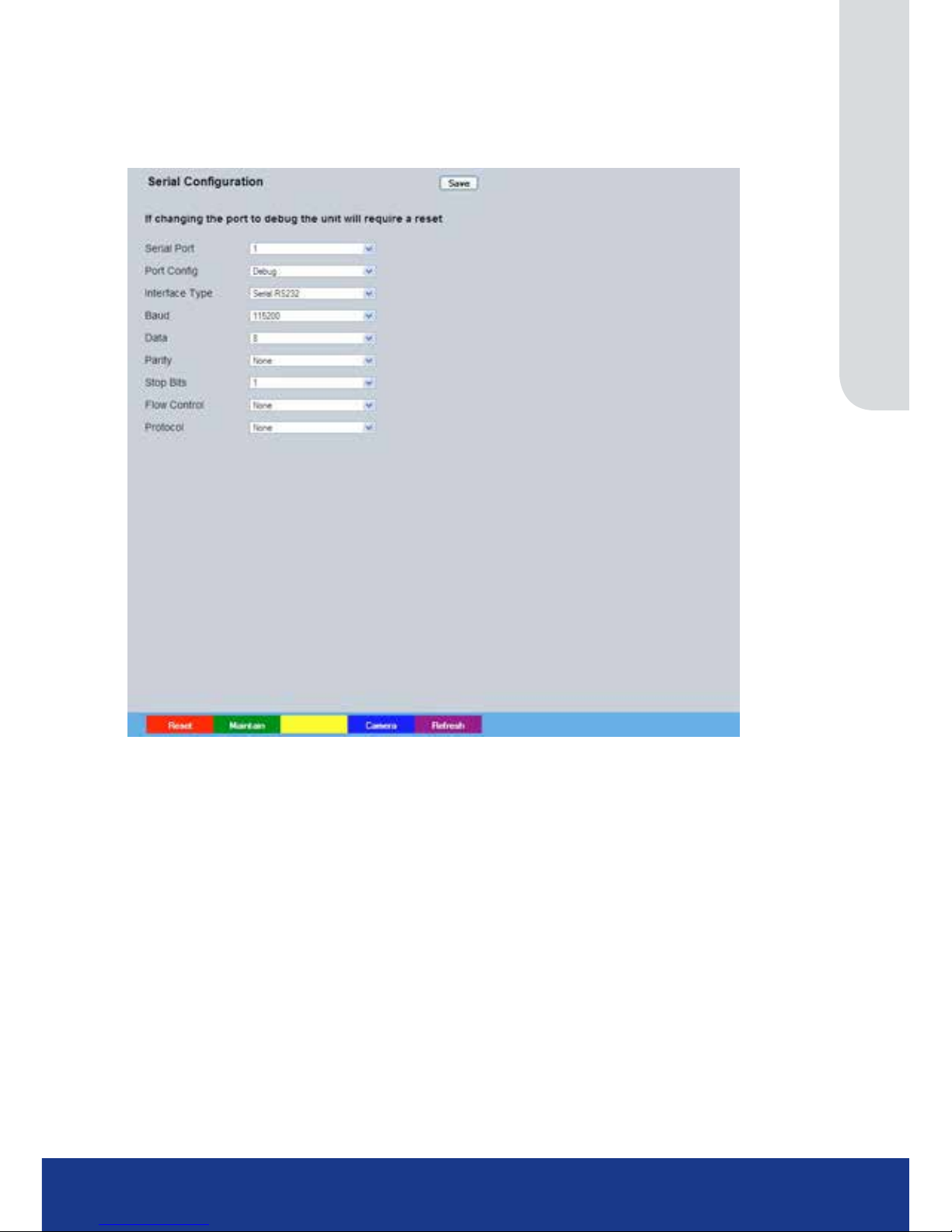
This menu allows conguration of the unit’s Serial ports, refer to ‘Installing the Unit’ for
installation information.
Serial Port These are the two serial ports available.
Port Cong The serial ports can be congured to specic uses.
Select from:
None Switches port off
Disabled Port is disabled
Debug Sets port for serial communications
Telemetry Sets port for Telemetry purposes
General Sets port for general purpose connections
EPOS Sets the serial port for connection to an EPOS
(Electronic Point Of Sale) device
LED Box Sets the port for connection to a TransVu LED Status Box.
Interface Type Choose the type of serial interface being used. Select from ;
COM1 - RS232
COM2 - RS485 & RS422.
Baud These options allow the Serial port communication settings to be congured.
Parity These options allow the Serial port communication settings to be congured.
Data These options allow the Serial port communication settings to be congured
Stop These options allow the Serial port communication settings to be congured.
Flow Control These options allow the Serial port communication settings to be congured.
Protocol This is a drop down list of serial telemetry protocols supported by the unit.
Note: When a telemetry protocol is selected, these settings will default to pre-determined values and
should not normally be altered.
Page 28
TransVu Compact
28
Power Manager
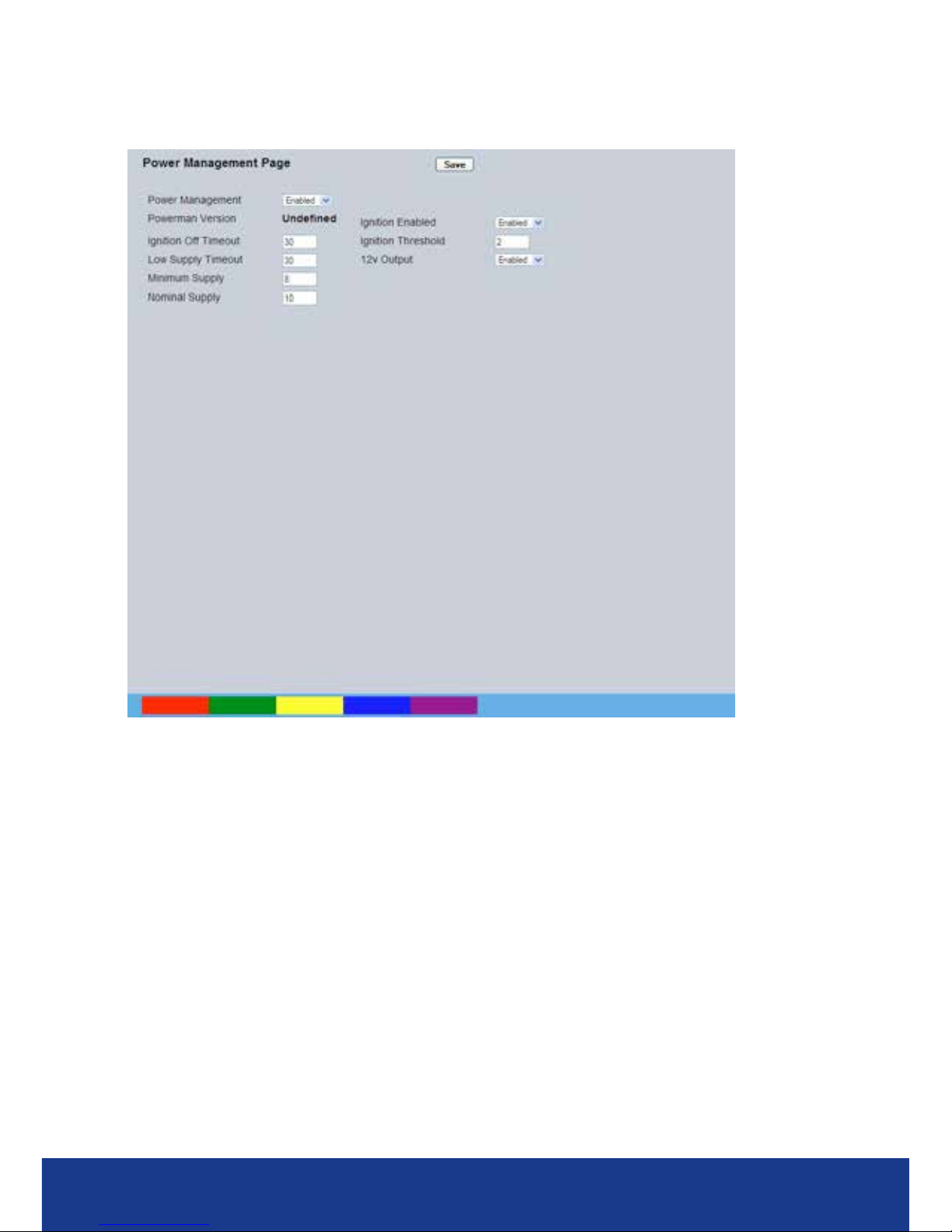
This menu allows conguration of power management and ignition line control functions.
Power Management Select ‘Enabled’ to activate all congured Power
Management functions.
Powerman Version Details the version number of the installed Powerman controller
software.
Ignition Off Timeout Enter a time (in seconds) from the ignition being switched Off to the unit
powering down.
Low Supply Timeout Enter a time (in seconds) from a low voltage supply being detected to the unit
powering down.
Minimum Supply Enter the minimum voltage level at which the unit will commence a forced
shutdown.
Nominal Supply Enter the nominal voltage at which the Low Supply Timeout function will
activate.
Ignition Enabled Select ‘Enabled’ to activate the ignition timeout control.
Ignition Threshold Enter the minimum ignition voltage required to start the unit up.
12v Output Enable/disable the 12v output supply from the unit
Page 29
www.transvu.co.uk
Configuration & Operation Guide
29
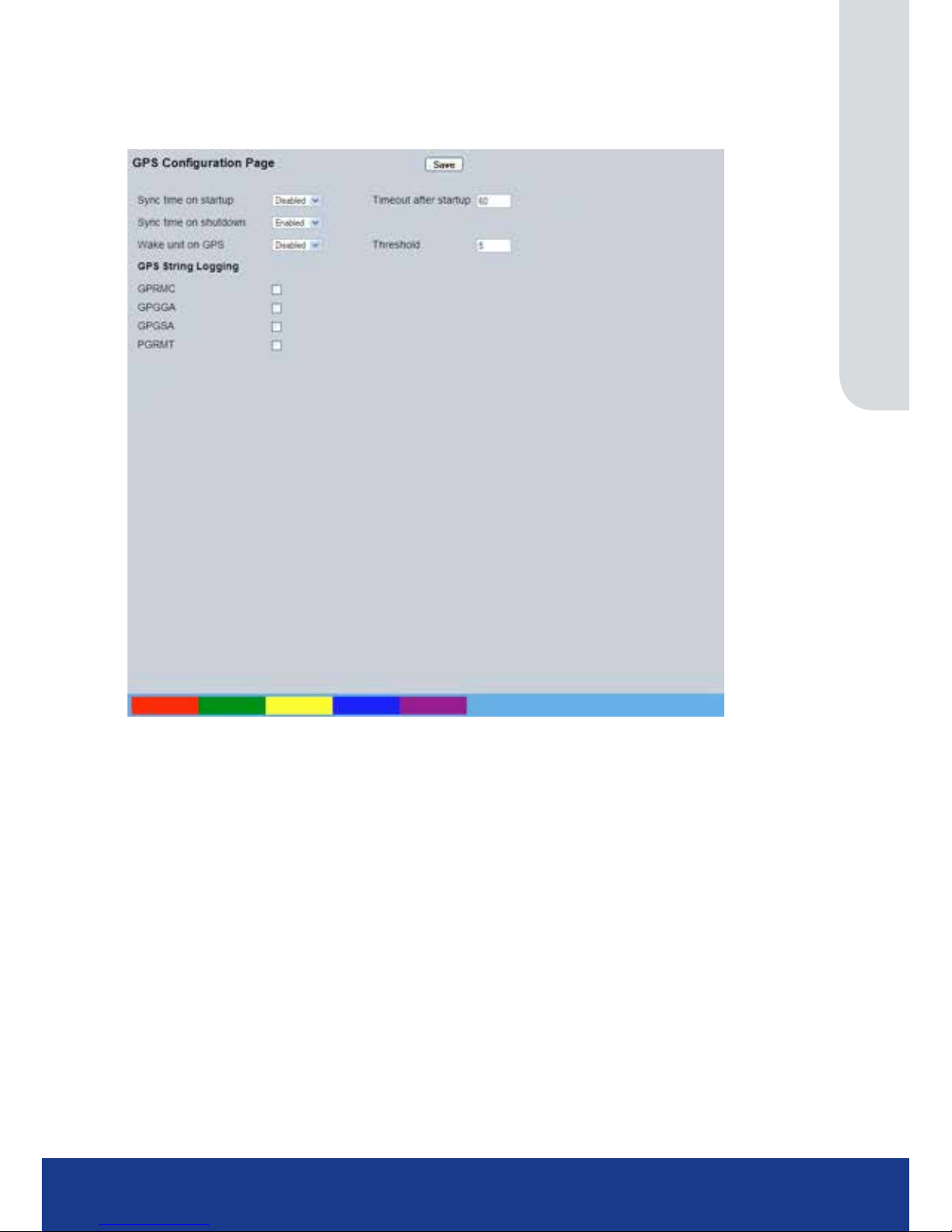
GPS Settings
This menu allows conguration of the attached Global Positioning System interaction.
Sync time on startup The unit will synchronise to GPS time when the system boots
Sync time on shutdown The unit will synchronise to GPS time when the system switches off
Timeout after startup Enter the time in seconds after which the application will stop attempting to
synchronise to the GPS device
GPS String Logging The option allows selection of which strings from the GPS are logged. The
options are GPRMC, GPGGA, GPGSA and PGRMT. These strings detail the
status of the GPS unit including position, status and date and are saved to le.
Wake unit on GPS Enable or Disable the feature. This uses the Threshold as the speed in MPH at
which the unit will wake.
Threshold The speed in MPH used by the Wake Feature
Page 30
TransVu Compact
30
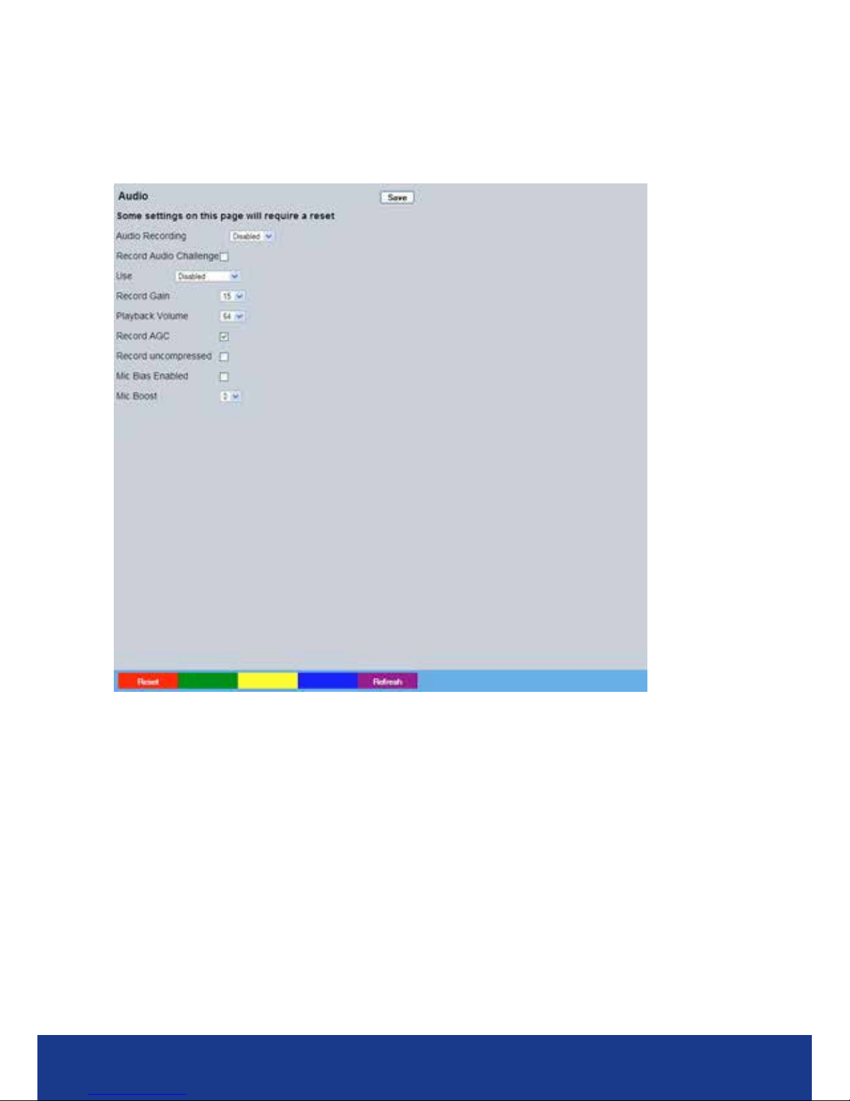
Audio
The Audio menu allows settings for the bi-directional audio channels to be edited. Audio can be
recorded from line input. Challenge audio i.e.originating from an Operator using NetVu ObserVer at
a Remote Video Receiving Centre (RVRC) can be recorded. This combined audio is then available
on Audio Output 1.
Audio Recording Select ‘Enable’ to activate Audio recording.
Record Audio Challenge Select this option to record an audio challenge originating from an operator at
an RVRC.
Use Select the intended use of the incoming audio i.e. ‘Local Playback’, or
‘Challenge’. Select ‘Disabled’ to deactivate.
Record Gain This option allows the Record Gain level to be set. This is the base setting from
which the AGC (Automatic Gain Control) will operate. Select from 1 to 15. The
default and recommended setting is 15.
Playback Volume Select a volume setting between 1 to 64 for audio playback.
Record AGC Select this option to activate the Automatic Gain Control (AGC) function. AGC
amplies audio until a recordable (usable) signal is produced. Please note that
this may result in increased background noise/distortion.
Record uncompressed Select this option to record audio in an uncompressed format.
Note: Recording in uncompressed format will signicantly increase the disk space used.
Mic Bias Enabled Enables the Audio input to receive MIC input.
Mic Boost Increases gain on Audio channel to boost MIC signal.
Page 31
www.transvu.co.uk
Configuration & Operation Guide
31
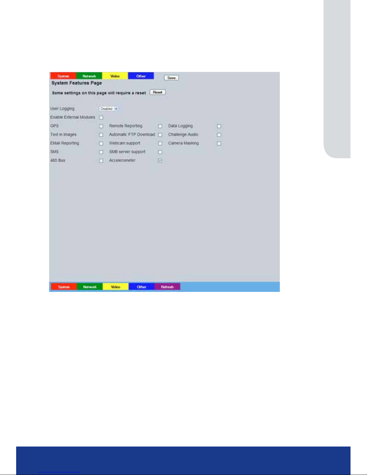
Features
This menu enables the activation of system features such as Email Reporting and the establishment
of display congurations for both PAL and NTSC monitors. There are a series of sub menus
accessed by using the coloured buttons at the top of the page.
System (red button)
User Logging Enable this option to activate User Logging. Refer to ‘Appendix C’ for further
information regarding the User Logging function.
Enable External Modules Select to enable any connected RS485 alarm modules.
GPS Select this option to activate the GPS (Global Positioning System) function,
refer to ‘System Settings->Status-GPS Status’ for information regarding the
GPS unit.
Remote Reporting Select this option to activate the Remote Reporting function, refer to ‘Network
Settings-Remote Reporting’ for more information.
Note: When de-selected here, the ‘Remote Reporting’ menu will no longer be displayed in
the menu tree.
Data Logging Select this option to activate the Data Logging function, refer to
‘Alarm Settings-Data Logging’ for more information.
Note: When de-selected here, the ‘Data Logging’ menu will no longer be displayed in
the menu tree.
Text in Images Select this option to activate the Text in Images function, refer to ‘Analytics &
Text-Text In Image’ for more information.
Note: When de-selected here, the ‘Text in Image’ menu will no longer be displayed in
the menu tree.
Page 32

TransVu Compact
32
Automatic FTP Download Select this option to enable automatic FTP downloads, refer to ‘Network
Settings-FTP Download’ for more information.
Note: When de-selected here, the ‘FTP Download’ menu will no longer be displayed in
the menu tree.
Challenge Audio Audio originating from an Operator at an Remote Video Receiving Centre
(RVRC) can be recorded.
Email Reporting Select this option to activate the Email Reporting function, refer to ‘Network
Settings-E-mail’ for more information.
Note: When de-selected here, the ‘Email Reporting’ menu will no longer be displayed in
the menu tree.
Webcam Support Select this option to activate the Webcam function. This allows the unit to
emulate a webcam and send image from one video feed in webcam format,
refer to ‘Network Settings-Web Cam’ for more information.
Note: When de-selected here, the ‘Web Cam’ menu will no longer be displayed in
the menu tree.
Camera Masking Select this option to activate the Camera Masking function, refer to ‘ Alarm
Settings-Camera Masking’ for more information.
Note: When de-selected here, the ‘Camera Masking’ menu will no longer be displayed in
the menu tree.
SMS Select to use Short Messaging Service (SMS). Suitable external hardware is
required. Refer to Appendix B for further guidance
SMB server support Select this option to activate the SMB (Server Message Block) le sharing
function.
When activated, the SMB protocol allows the unit to access PCs operating
the Windows operating system (and Linux machines running Samba). This
enables sharing of les and directories to/from the unit. The name of the SMB
Workgroup on the network must be correctly entered in the SMB Workgroup
option (see below). It is important that the Server Name assigned to the unit via
‘Network Settings->Server Name’ is unique within the workgroup being used.
To access the unit via a PC running SMB (and has access to the same
Workgroup); open My Network Places-Entire Network-Microsoft Windows
Network. The Workgroup containing the unit and PC(s) should then be
available. Files and folders can then be copied/added as required.485 Bus
Accelerometer Select this option to activate the Accelerometer function, refer to ‘ Alarm
Settings-Accelerometer’ for more information.
Note: When de-selected here, the ‘Accelerometer’ menu will no longer be displayed in
the menu tree.
Page 33
www.transvu.co.uk
Configuration & Operation Guide
33
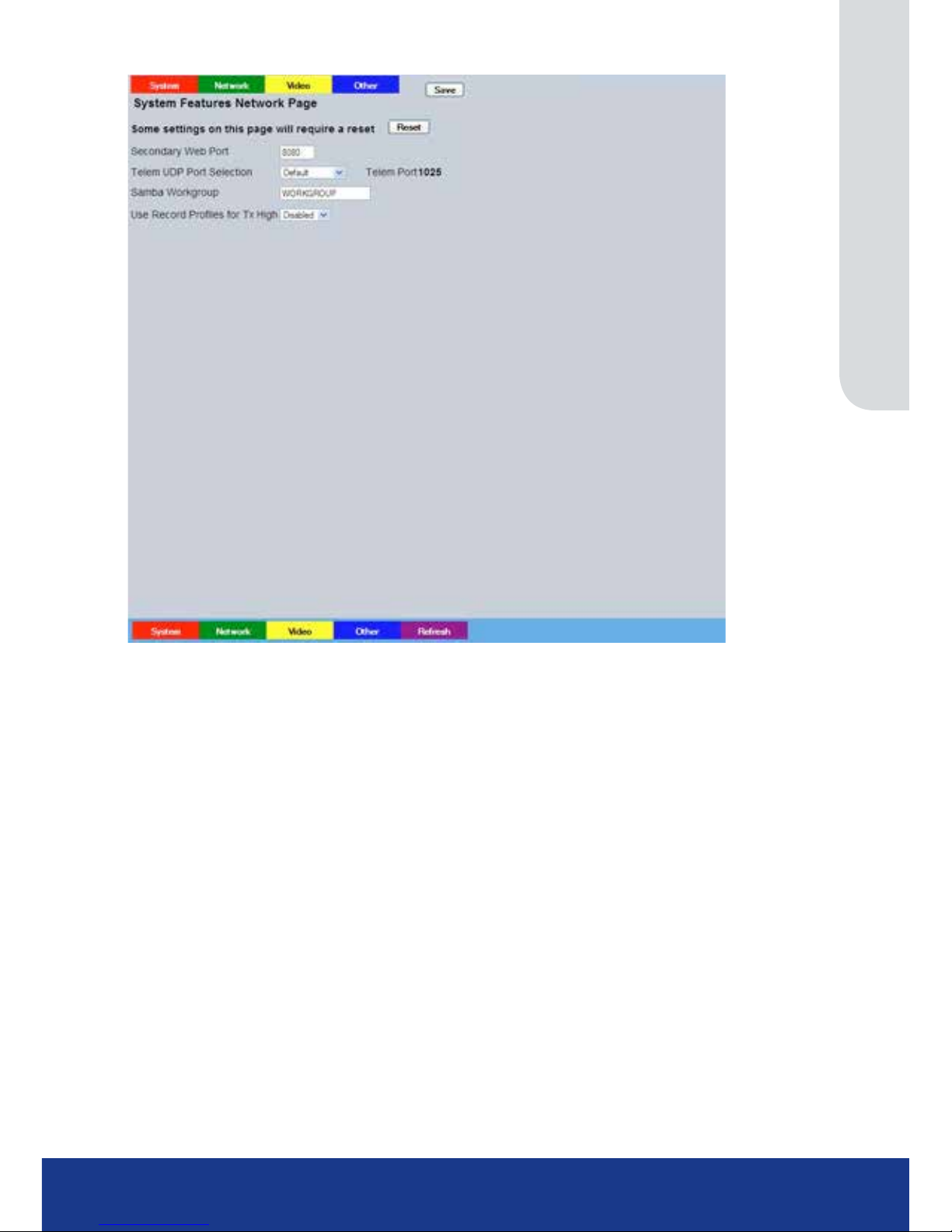
Network (green button)
Secondary Web Port If the default port setting for web serving has already been allocated, it is
possible to congure a second port number
i.e. the secondary web port can be set to 8000 if the default web port (80) is
blocked by the network or rewall.
Telem UDP Port Selection Select ‘Automatic’ to enable the unit to select a suitable port for telemetry
purposes.
Select ‘Default’ to use the default port settings (1025).
Select ‘User Dened’ to use settings entered in the ‘Telemetry Port’ option.
Telemetry Port Enter the port settings for telemetry data here. The default setting is 1025.
Note: This option will only be displayed when ‘User Dened’ is selected in the Telem UDP Port Selection
option.
Samba Workgroup Enter the Samba (SMB) Workgroup details.
Note: A unit reset is required to activate/update Samba (SMB) Workgroup details, refer to Features ->
System -> ’SMB Server Support’ for more details.
Use Record Proles For Tx Select this option when units required Video Transmission prole
(rate/quality/resolution) is identical to that being recorded.
Page 34
TransVu Compact
34
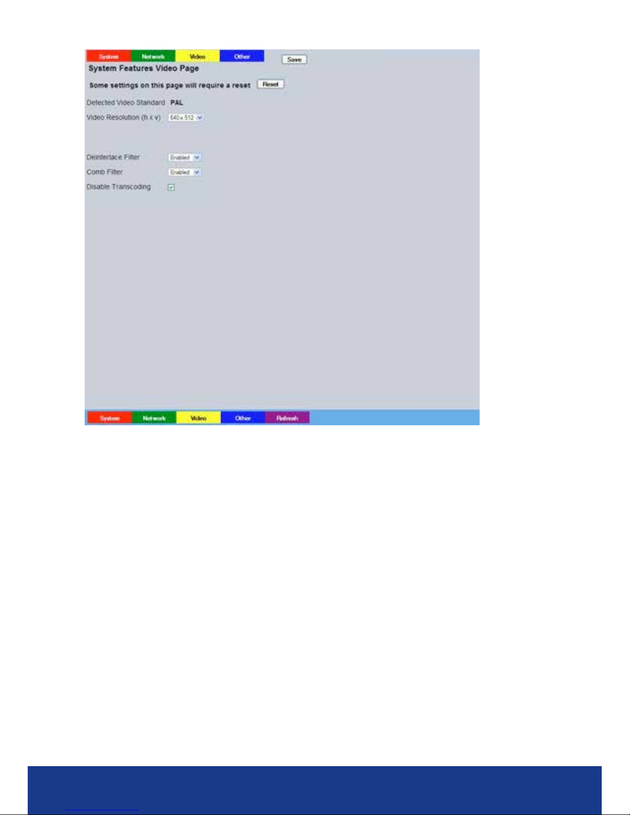
Video (yellow button)
Detected Video Standard The unit automatically detects the video standard being used i.e. PAL/NTSC.
Horizontal/Vertical Edit the resolution settings. This will be the fundamental resolution for the unit.
Deinterlace mask Select this option to improve display clarity and minimise the comb effect that
may be visible when recording high motion scenes in 4CIF mode.
Comb Filter Enable this option to activate the Comb Filter function. Comb Filter can help
improve the ne details of a video signal image by ltering the luminance and
chrominance separation process.
Disable Transcoding Select to disable the unit’s transcoding capabilities. In normal circumstances this
should always remain enabled, however it can be useful to disable the feature
when conducting maintenance.
Page 35
www.transvu.co.uk
Configuration & Operation Guide
35
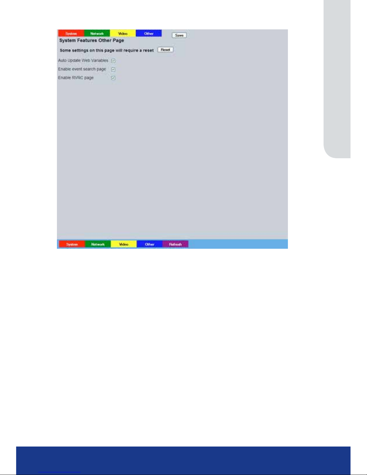
Other (blue button)
A
uto Update Web Variables
Congures the unit to update all system variables required for an automatic
upgrade without requiring conrmation. Do not check this box if you run a
customised applet.
Enable Event Search Page
Select to enable the Event Search option. When enabled, the option will appear
within the Conguration Menu tree. Refer to ‘Navigating the Conguration
Menus->Event Search’ for further details.
Enable RVRC page Select this option to activate the RVRC Remote Set/Unset/Override function,
refer to ‘Record Settings-RVRC’ for more information.
Note: When de-selected here, the ‘RVRC’ menu will no longer be displayed in the menu tree.
Page 36
TransVu Compact
36
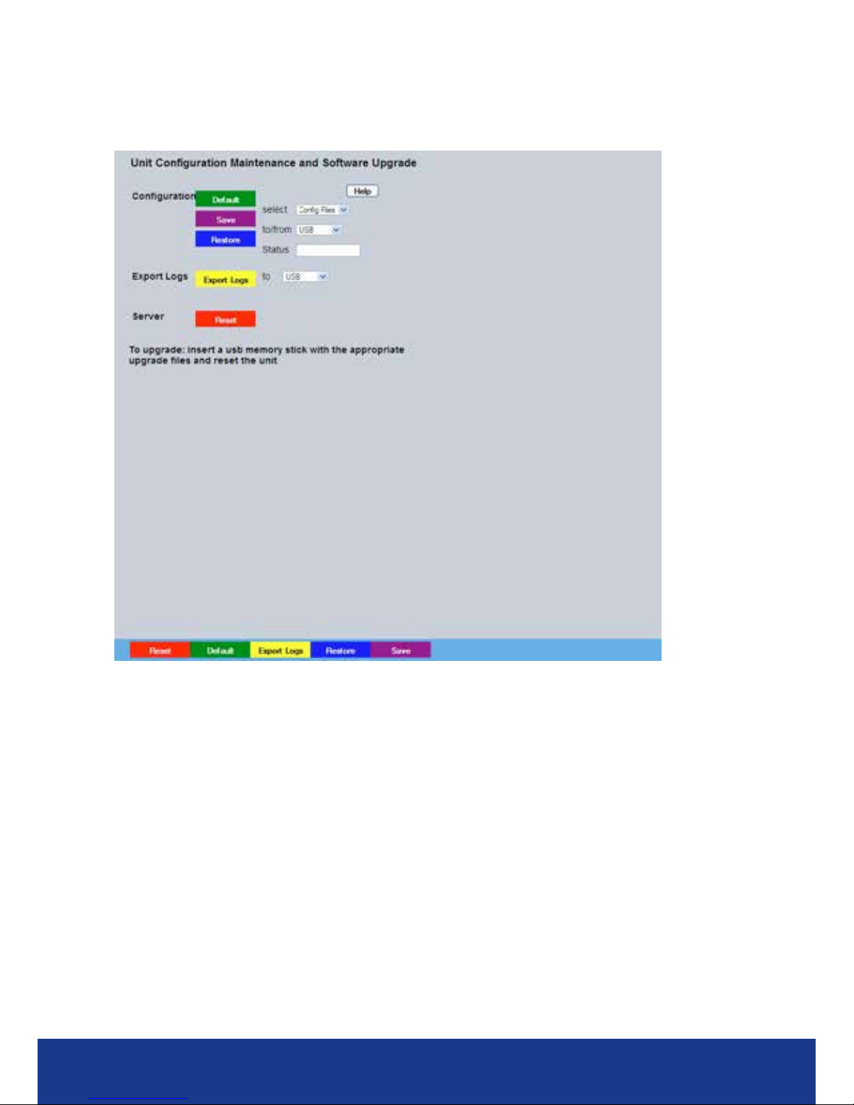
Maintain
This menu allows the unit to be reset and a software upgrade to be performed via a connected USB
device. Current unit
settings can also be saved for future use and previousl
y saved settings restored.
Conguration
Default (Green) Select to return the unit to its factory default settings.
Note: Selecting the Default button will cause the system to reboot.
Save (Purple) Select to save current unit settings to the selected media.
Restore (Blue) Select to restore previously saved settings from the selected media.
Note: Selecting the Restore button will cause the system to reboot.
To/From Select the relevant media device to save to or restore from i.e. USB.
Export Logs
Export Logs (Yellow) Select to export all Logged data to a connected
external device.
To Select the relevant media device to save to export to.
Server
Reset (Red) Select to cycle the power to the unit.
IMPORTANT: To upgrade the unit, insert a media device containing relevant software upgrades
and select ‘Reset‘.
Note: For the latest software upgrades, please refer to the website: www.dedicatedmicros.com
Page 37
www.transvu.co.uk
Configuration & Operation Guide
37
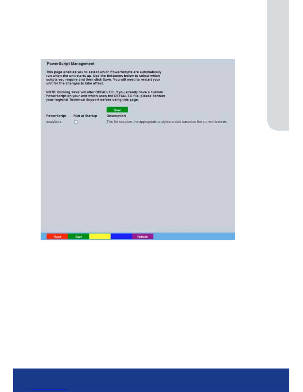
PowerScript Mgmt
This menu enables installed PowerScripts to be activated/deactivated on start-up. Use the
tickbox(es) to select/deselect installed PowerScripts, then select Save (Green). A system reset will
be required for the changes to take affect.
Note: Changes this page will alter the ‘Default.C’ le. If you already have a custom PowerScript on your
unit which uses Default.C, please contact AD Technical Support for guidance Tel: +44 (0) 845 600
9502 for further guidance.
Page 38
TransVu Compact
38
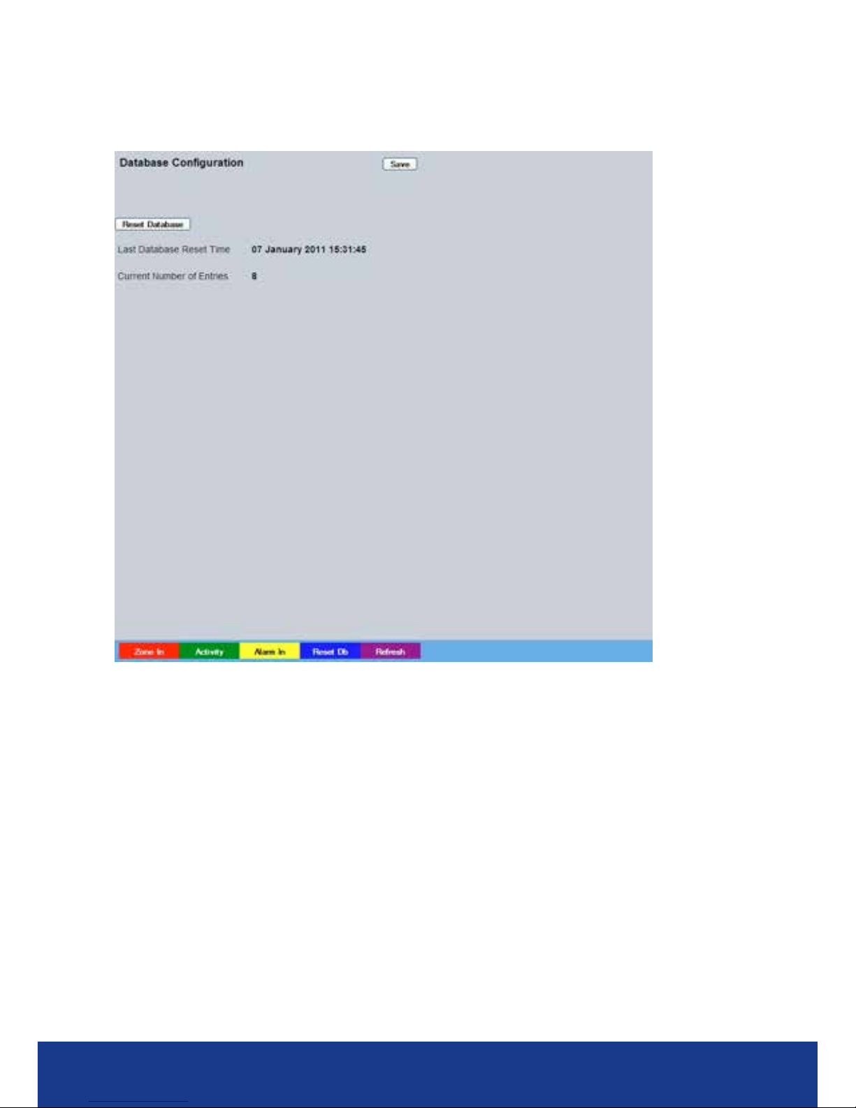
Database
The database records all events registered by the unit. This page allows the database to be reset,
and can be used to limit the number of entries held in it.
Function Description
Last database reset time This read only section is generated by the unit and identies the last time that
the database was reset.
Current number of entries This read only section shows how many events are held in the database.
Reset database This button will clear the database and set the last reset time to the current time
and date.
Page 39

www.transvu.co.uk
Configuration & Operation Guide
39
Console Settings
The menus under the Console Settings heading allow the unit’s Viewer display settings to be altered
and User Account details to be viewed and changed.
The Viewer Defaults page allows the Viewer menu settings to be congured.
The Display page controls how the local monitors present information. They control whether text
will be displayed on the Main or Spot monitors, the colour of that text, and how long cameras being
displayed in sequence will be shown on screen.
The Map Cong page allows images to be imported and used as maps displayed in the Viewer
menus. Hot spots can be added to allow quick navigation to individual cameras.
The Map Data page allows Map Cong information to be saved for future use. Previously saved
data can also be uploaded.
The User Accounts page helps protect conguration procedures by limiting access to specic users
via accounts and passwords.
Page 40
TransVu Compact
40
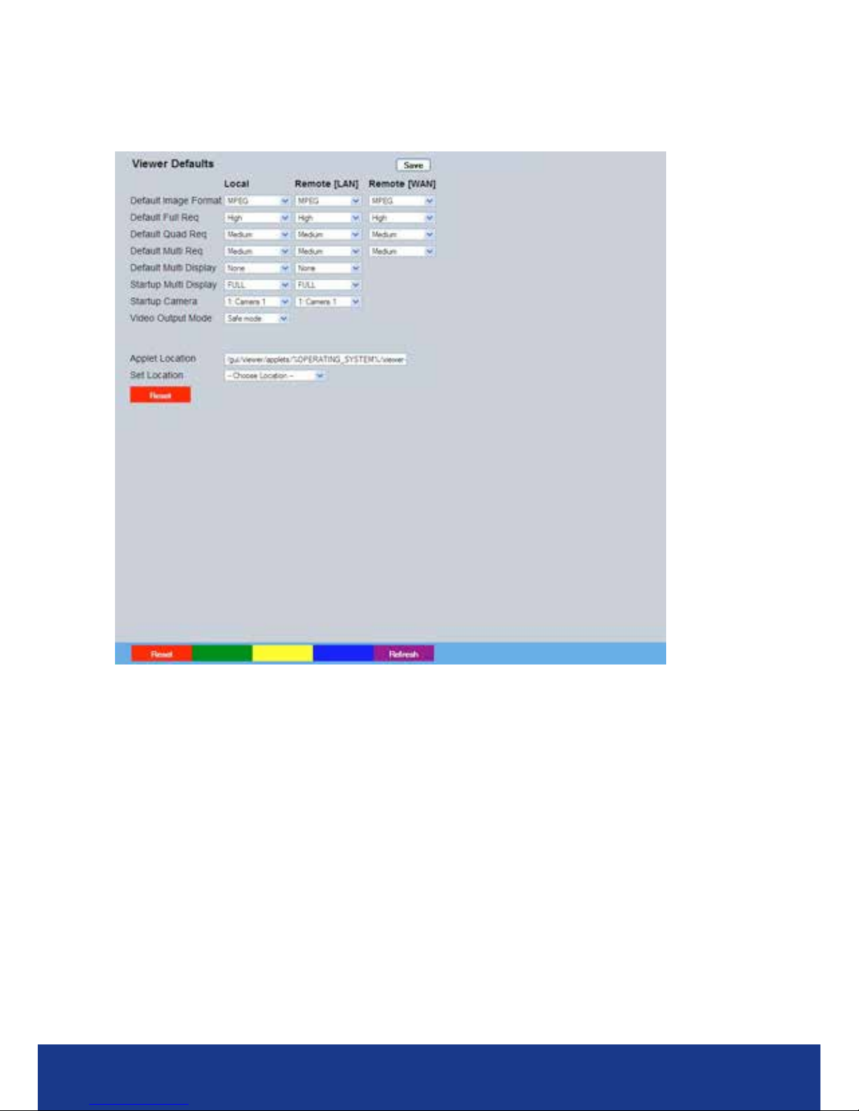
Viewer Defaults
This menu allows conguration of settings for the Viewer function, refer to ‘Operating The Viewer’ for
more information regarding this feature
Default settings can be congured for accessing the Viewer function via a local monitor and also
remotely via a network connection.
Default Full Req Images displayed full screen in the Viewer menus can be shown in either High
Medium or Low resolution.
Default Quad Req Images displayed in Quad format in the Viewer menus can be displayed in
either High Medium or Low resolution.
Default Multi Req Images displayed in Multi format in the Viewer menus can be displayed in either
High Medium or Low resolution.
Default Multi Display When accessing the Viewer function, select the display format which will initially
be displayed.
Startup Multi Display When accessing the Viewer function, select the display format which will initially
be displayed.
Startup Camera When accessing the Viewer function, select the camera image which will
initially be displayed. If one of the multi display formats has been selected
via the ‘Startup Multi Display’ option, the camera channel selected here will
be displayed in rst (top left) position. Subsequent camera channels will be
displayed in sequential order.
Video Output mode Select the display output that best suits the viewing monitor. Typically PAL
Default is most suited for a CRT monitor, PAL Reduced for a TFT monitor.
Select from:
PAL Default
PAL Reduced
Page 41

www.transvu.co.uk
Configuration & Operation Guide
41
Note: It will be necessary to reboot the unit to implement any change to the Video Output Mode. The unit
can be rebooted via the Reset (Red) option.
Decoder Mode Select from Normal Display or Decoder Mode. Normal Display allows cameras
to be accessed and controlled via the Viewer menu. In Decoder Mode,
connected cameras can
be accessed, viewed or controlled via Dedicated Micros Pick-a-Point system.
Note: For further information regarding Dedicated Micros Pick-a-Point system, please contact Dedicated
Micros customer services in your region.
Mouse Sensitivity The sensitivity settings of the mouse can be adjusted from the least sensitive
(1) to the most sensitive (10). The setting can be adjusted via the slidebar or a
number entered directly into the accompanying textbox. The default setting is 4.
Applet Location The location of the unit’s Viewer menu applet is displayed. The default location
will always be the applet installed on the unit. If accessing multiple units via a
remote connection, all can be assigned the same Viewer applet. This will lessen
the load time required when accessing different DVRs/Servers.
For example, if a local unit and a remote DVR are to be accessed, it is possible to
set the Applet location for both DVRs as the local unit.
If viewing the unit remotely, Dedicated Micros provide a remote
applet. This remote applet can be selected via the ‘Set Location’ option. The
applet is located on the website (www.dedicatedmicros.com/software_release/
index_rmware.php). Due to possible bandwith restrictions on the network the DVR
is located, using this remote applet may improve data transfer speeds.
Set Location Select the applet location. Choose from ‘Default location’ i.e. the applet installed
on the unit; or the ‘website’ option i.e. the
remote applet.
Reset (Red) Select to reset the unit and implement any changes made to the ‘Video Output
mode’ or ‘Applet Location’ elds.
Page 42
TransVu Compact
42
Display
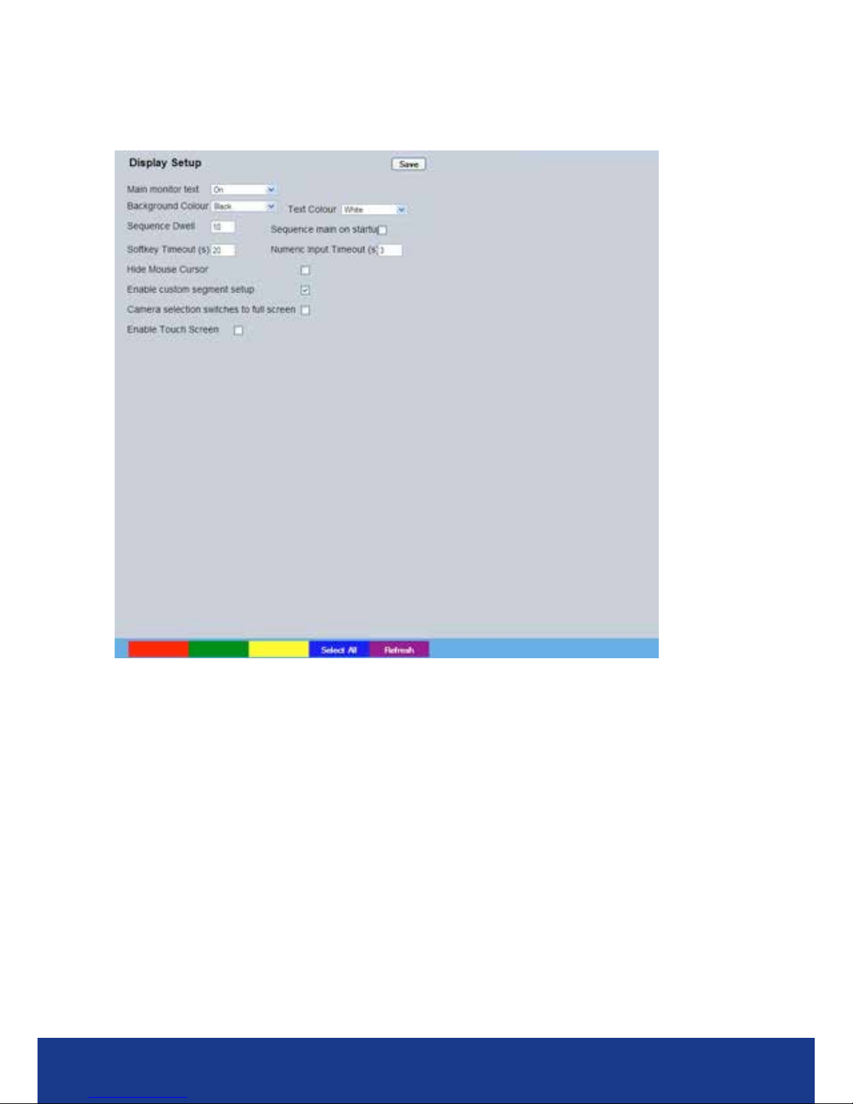
This menu allows conguration of monitor settings used when viewing camera images and
text data.
Main monitor text It is possible to select text to be displayed on the main monitor. The text
displayed will include; time, date, mode of operation (Set, Unset or Override),
camera number and camera title.
Background Colour A black background appears by default around the text. It is possible to change
the colour of this background. Select from the options available in the drop
down list.
Text Colour The colour of the displayed text can be changed. Select from the options
available in the drop down list.
Sequence Dwell (secs) The sequence dwell time can be set from 1 to 99 seconds. The dwell time is the
period a camera’s images are displayed before switching to the next camera in
the sequence.
Sequence
main on startup
Select to sequence live views from all connected cameras on the main monitor
upon system start-up.
Softkey Timeout Enter the number of seconds unused key inputs on the monitor output will be
displayed before disappearing.
Enable
custom segment
setup
Select to activate the custom segment setup feature. When selected, a user can
congure a Quad or Multiscreen layout via the Viewer menu. The congured
layout can include any camera in any available segment.
Camera selection switches
to full screen Select to auto switch to full screen mode any camera channel selected from
Multi display (selected via the Viewer feature).
Select All (Blue) Select to add all available cameras to the Spot Monitor Sequence.
Page 43
www.transvu.co.uk
Configuration & Operation Guide
43
Map Cong
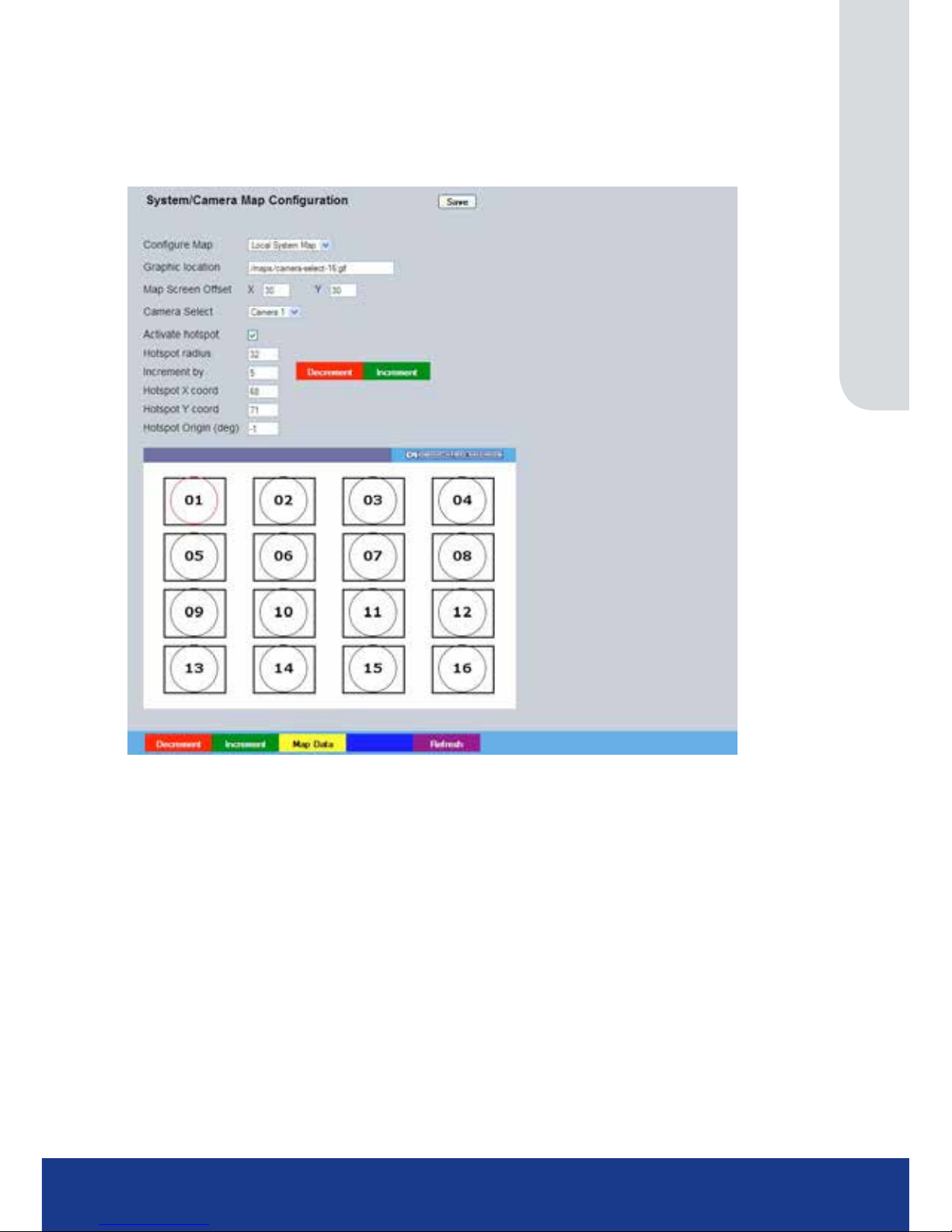
This menu allows images to be imported and used as maps that can be displayed in the Viewer
Menus. The map can then have hotspots added to allow quick navigation to individual cameras.
An overview ‘System Selection Map’ can also be added to navigate between different systems.
Congure Map Leave as ‘Local System Map’. This is the map from which connected cameras
can be accessed.
Graphic Location Enter the location of the relevant map graphic, including the full I.P address
of the server holding the map. The map image will be displayed if linking is
successful. The linked map can be in gif or jpeg format and should not exceed
500 by 350 pixels.
Map Screen Offset These coordinates represent the top left corner of the map graphic as displayed
in the Viewer menu.
Camera Select Select which camera is to be linked to the created hotspot.
Activate Hotspot Select to activate and display the camera hotspot.
Hotspot Radius Enter the radius (in pixels) of the hotspot.
Increment by If using the Decrement (Red) or Increment (Green) buttons, enter the size (in
pixels) that the hotspot will increase/decrease.
Decrement (Red) Select to reduce size of hotspot.
Increment (Green) Select to increase size of hotspot.
Hotspot X coord Use to position the centre of the hotspot along the X axis e.g. entering 20 would
place the hotspot centre 20 pixels from the left edge of the map.
Hotspot Y coord Use to position the centre of the hotspot along the Y axis e.g. entering 20 would
place the hotspot centre 20 pixels from the bottom edge of the map.
Note: The hotspot can also be positioned by clicking directly on the map.
Page 44

TransVu Compact
44
Hotspot Origin (deg) This option should be used when the hotspot relates to a Dedicated Micros
Oracle Dome camera. Clicking the hotspot will send the Oracle Dome camera to
a pre-determined view (absolute positioning). However if the dead centre of the
hotspot is selected, the camera will be viewed from its current location.
The absolute positioning point will depend on the data entered here. A setting
of ‘0’ would result in the camera facing its Original (base) position. To change
the preset position, enter a number between 1 and 360. A setting of 20 would
set the preset position to 20 degrees to the right of its ‘origin’ position, 180
would send it to face in the opposite direction (of its base position) . Refer to the
‘Viewer Menus-Program menu‘ for information on establishing an Origin position
for a PTZ camera.
Page 45
www.transvu.co.uk
Configuration & Operation Guide
45
Map Data
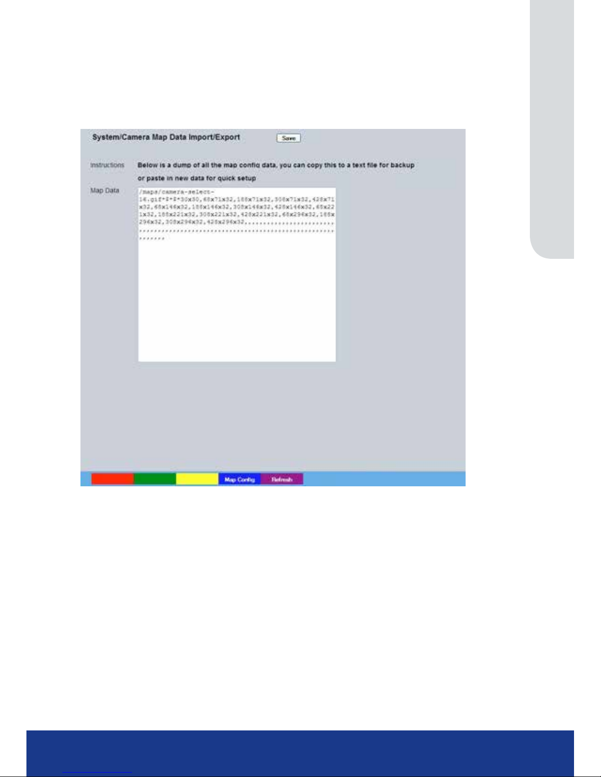
The Map Data menu allows Map Cong data to be Imported/Exported. This enables map data to be
saved and stored for future use, or used between multiple units.
Note: The Map Data menu will only be available when viewing the menu pages remotely i.e. via the
webpages.
To save map data, highlight and copy all text displayed in the Map Data text window, then save this
data as a text le.
To import data, copy relevant text from an external location and paste into the Map Data text
window. When the menu is exited, this data will be used as the Map Cong settings.
Note: If importing data, remember to rst save any current map data as required.
Page 46
TransVu Compact
46
User Accounts
The unit can protect conguration procedures by limiting access via usernames and passwords.
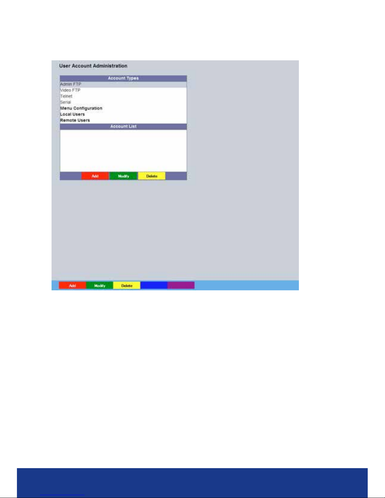
Account Types The available account types for which users and passwords can be assigned
privileges are:
• Admin FTP
Assigning username and password requirements for the Admin FTP
function will limit access to the unit via an FTP connection.
• Video FTP
Assigning username and password requirements for the Video FTP function
will limit access to the Video FTP archiving feature (used with DM’s NetVu
ObserVer).
• Telnet
Assigning username and password requirements for Telnet connections
will limit Telnet access to the unit (Telnet can be used to upgrade the
unit).
• Serial
Assigning username and password requirements for Serial connections will
limit access via a Serial link.
• Menu Conguration
Assigning Menu Conguration access privileges will limit access to the
Conguration menus when viewed locally. When implemented, the user
will be prompted for a username and password before access to the
Conguration menus (via the main menu) will be granted.
Page 47

www.transvu.co.uk
Configuration & Operation Guide
47
• Local Users
Assigning Local Users access privileges will limit access to the Viewer
pages for local users. When implemented, the local user will be prompted
for a username and password before access to the Viewer pages (via the
main menu) will be granted.
• Remote Users
Assigning Remote Users access privileges will limit access to the Viewer
pages for remote users. When implemented, the remote user will be
prompted for a username and password before access to the Viewer pages
(via the main menu) will be granted.
When granting access privileges to Local and Remote Users, it is possible to limit access to specic
cameras. Using the Camera Selection segment of the Add New Account menu, enter those cameras
for which access will be permitted. Select the cameras in accordance with the input channel they’re
connected to on the rear of the unit. For example, if wanting to allow access to camera 1 to 3
inclusive, enter: 1-3. If wanting to grant access to cameras 1,3 and 6, enter 1,3,6. If no camera data
is entered, access will be allowed to all connected cameras in both live and playback modes.
Note: There are no default usernames and passwords for any of the Account Types. If none are
assigned, access will be granted to all users and no request for a username and password will be
made.
Account List
When an Account Type is highlighted, details of users with access will be displayed.
Add Highlight an administration feature i.e. Serial and select ‘Add’. Enter the new
User Name and Password. That user’s name will now be displayed in the
account list.
Modify/Delete To modify or delete a user’s settings, highlight the user in the list and press the
relevant button to Modify or Delete.
Note: If viewing the User Accounts page via a local monitor and navigating with the I.R Remote Control.
Press the right directional button from the menu tree to access the Account List.
Page 48

TransVu Compact
48
Camera Settings
The Camera Settings menus allow conguration of cameras connected to the unit. Refer to the
individual menus for further details.
The Setup page allows the quick conguration of all connected local camera channels.
The Overview menu details the general settings assigned to each of the local camera channels.
The IP Stream Inputs page allows third party IP cameras to be integrated into the unit.
The Camera Setup page allows the colour and contrast settings for each individual camera to be
adjusted (with a dynamic preview available).
The Camera Telemetry page enables telemetry capable cameras to be congured.
Page 49
www.transvu.co.uk
Configuration & Operation Guide
49
Setup
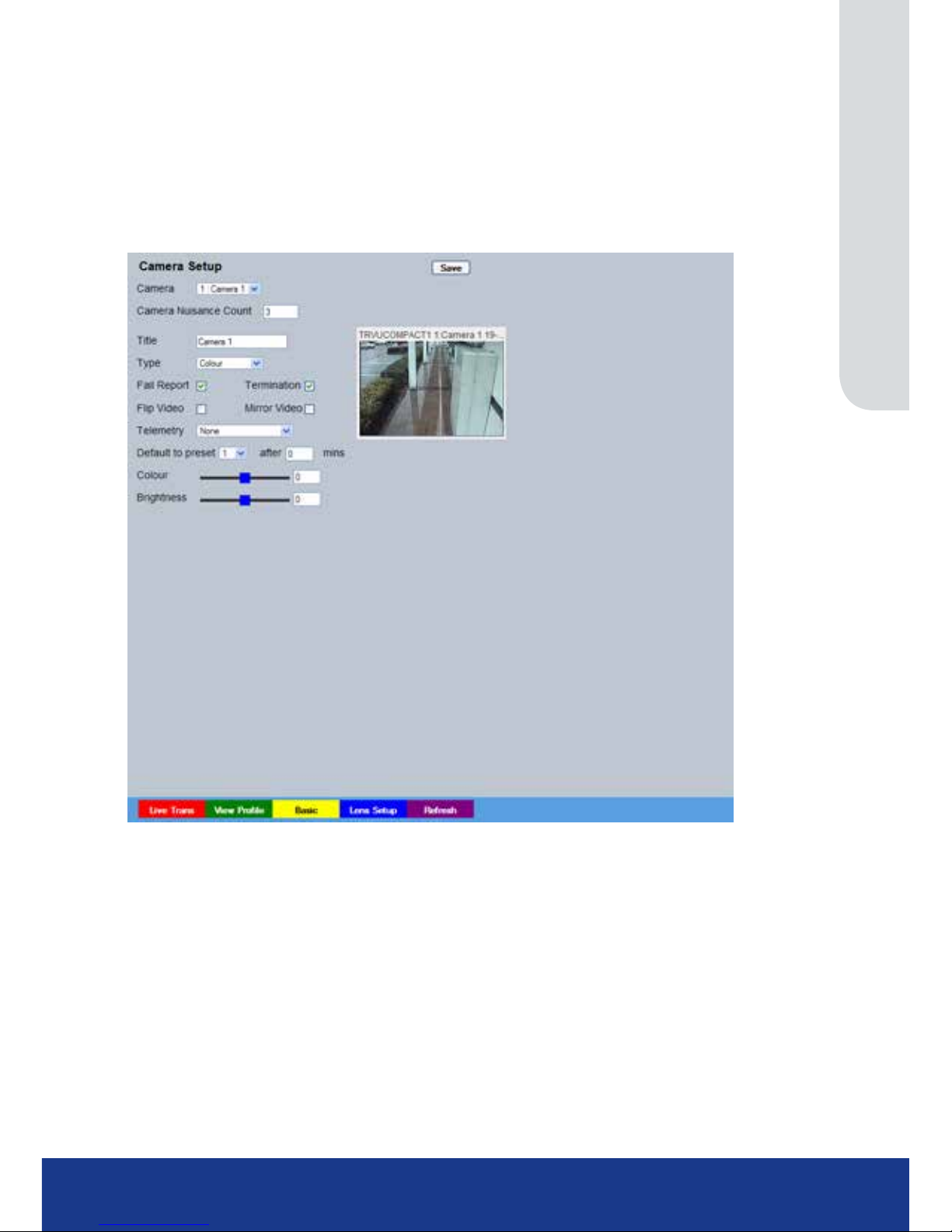
This menu allows the conguration of active camera channels.
IMPORTANT: The menu options displayed will differ depending on the camera ‘Type’ and ‘IP
Mode’ selected.
Note: Ideally any setup options available locally on the camera should rst be used to best obtain a
suitable image quality.
Mono/Colour Camera
Camera Select a camera channel for review and adjustment.
Camera Nuisance Count This is a repetitive detector value. When a camera failure alarm is received on
the unit, it will store the alarm time and monitor the number of times the same
alarm is triggered within an hour period. If the detector is triggered the number
of times entered here, the unit will set the camera to ‘No Connection’. To disable
this feature, leave the setting as ‘0’.
Title Assign a recognisable name to the camera. This will be displayed in all
references to the camera in the both the Conguration and Viewer menus.
Type The settings will default to ‘Colour’. If Monochrome cameras are used, select
‘Mono’. Selecting ‘Mono’ will remove colour patterning. Select’ ‘IP’ for an IP
Camera. If a particular channel is not in use or the camera has failed, select ‘No
Conn’.
IMPORTANT: The menu options displayed will differ depending on the camera ‘Type’
selected here.
Fail Rep Select this option to generate a Failure report in the event of camera connection
failure.
Page 50
TransVu Compact
50
Telemetry If a telemetry capable camera is connected, the appropriate control
protocol should be selected from the accompanying drop down list, refer to
‘Appendix G’ for details of supported
telemetry protocols.
Default to preset If a telemetry camera has been assigned a preset position, select the chosen
preset position here. Enter the time period (in minutes) of inactivity which will
result in the camera moving to its preset position,
refer to Viewer menus-
>Program Page for guidance on assigning camera presets.
after X mins Refer to ‘Default to preset’.
Note: The following settings will change depending on the type of camera connected.
If a Local Analog Camera is selected
Colour Select a colour value from -8 to +8 via the slidebar or enter a number directly
into the accompanying textbox.
Brightness Select a contrast value from -8 to +8 via the slidebar or enter a number directly
into the accompanying textbox.
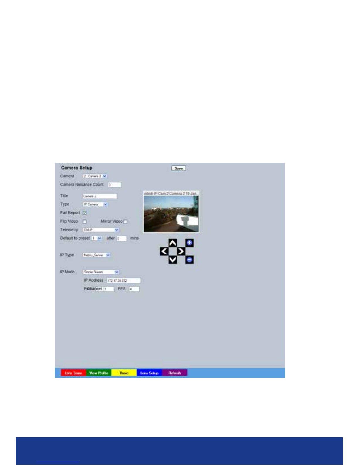
IP Camera
If a NetVu Connected IP Source is selected
IP Type Select the type of NetVu Connected source the camera stream is originating
from. Select from:
‘NetVu Server’ - i.e. DVIP Server, DVIP RT, SD,
SD Advanced, EcoSense.
‘NetVu Gen 2’ - i.e. DS2, BX2.
NetVu Camera’ - i.e. the CamVu 2000 from Dedicated Micros.
Page 51

www.transvu.co.uk
Configuration & Operation Guide
51
‘NetVu ANPR’ - i.e. the HyperSense ANPR camera from
Dedicated Micros.
IP Mode Select the IP mode used to receive incoming IP data. Select from:
Simple Stream - Received IP streams are non-compressed and are
viewed as congured on the originating source.
Recode Stream - When selected, the unit will recompress the
incoming IP stream to the record prole settings
established for this camera channel in the Prole
Record menu (Record Settings->Prole Record).
This feature is only accessable with 3rd party IP
camera when the 3rd party IP camera license has
been enabled.
Remote codec When selected, the unit will utilise the codec in
the remote NetVu connected video server/camera
to allow change Multimode proles and perform
additional activities such as VMD and Activity
Detection as if the codec was an integral part of the
DVR. If ‘Remote codec’ is selected, the loading on
the unit’s internal codecs will be reduced.
IMPORTANT: The Remote codec option is only applicable for NetVu Connected cameras.
Note: Additional IP cameras ( further to existing local camera channels) are remote codec only.
Therefore any NetVu connected cameras will be applied above local camera level.
When ‘Simple Stream’ and ‘Recode Stream’ are selected via ‘IP Mode’, the following options will
be available:
IP Address Enter the URL address of the image source.
Channel If the URL is a multichannel device (e.g. DV-IP NV1), this species which
channel to use.
Page 52

TransVu Compact
52
Basic
This menu allows the conguration of active camera channels.
Camera Nuisance Count If a camera is intermittantly losing connection (failing). The unit can be set to
ignore incoming data from that camera (after the specied number of failures
entered here). If the camera connection is restored and does not fail for 1 hour,
the camera wil be noted as operating correctly and the Nuisance Count reset.
Title Each of the camera titles can be edited for ease of use i.e. the camera type,
location or view description could be used.
Note: If a camera title is entered via the local monitor, an on-screen virtual keyboard will be displayed to
aid text entry.
Mode The settings will default to ‘Colour’. If Monochrome cameras are used, select
‘Mono’. Selecting ‘Mono’ will remove colour patterning. If a particular channel is
not in use or the camera has failed, select ‘Not Connected’.
Term Cameras that are not being looped through to another piece of equipment will
need to be terminated. Double termination (not removing termination from the
unit) will result in the 1V peak to peak video signal being crushed. This can
reduce the colour rendition of the video source and may cause the video signal
not to be detected by the last piece of equipment i.e. the signal is no longer 1V
peak-to-peak.
Fail Rep Select this option to activate a Failure report in the event of camera connection
failure.
Note: The arrow button displayed next to each textbox allows settings to be replicated for those cameras
listed below. This will only affect the adjacent option i.e. Mode arrow will replicate the Mode setting
to all cameras below the clicked arrow.
Page 53
www.transvu.co.uk
Configuration & Operation Guide
53
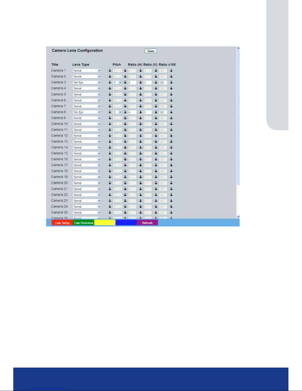
Camera Lens Conguration
This page allows different lens de-warping techniques to be applied to connected cameras. The unit
can de-warp Fish-eye and Depressive Fish-eye lenses to present a normal aspect image.
Title Shows the allocated name of the video source.
Lens Type Allows selection of sheye, depressive sheye and normal lens types.
Pitch Allows the image to be rotated counterclockwise by ninety degrees.
Ratio (H) Allows the horizontal ratio of a panamorphic lens to be set.
Ratio (V) Allows the vertical ratio of a panamorphic lens to be set.
Ratio x100 Allows the multiplier ratio of a panamorphic lens to be set.
Cam Setup (Red) Select to open the Camera -> Setup page
Cam Overview (Green) Select to open the Camera -> Overview page
Refresh (Purple) Refreshes the information on the current page.
Page 54
TransVu Compact
54
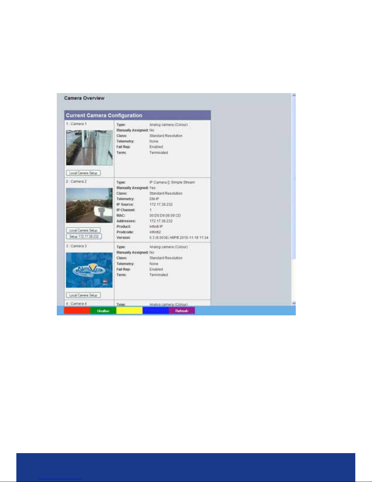
Overview
This menu details the general settings assigned to each of the local camera channels.
To edit the settings assigned to any of these cameras;
Click on Local Camera Setup to edit the settings held in the unit;
Click on ‘Setup’ to open the Setup menu on the connected video source.
CIP Settings (Red) Select to open the Closed IPTV->Settings page
Unalloc (Green) Select to open the Camera->Unallocated Cams page
Refresh (Purple) Refreshes the information on the current page.
Page 55
www.transvu.co.uk
Configuration & Operation Guide
55
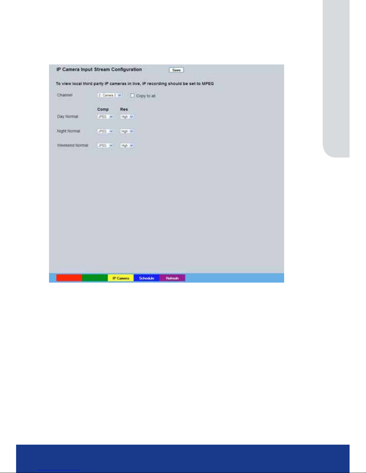
IP Stream Inputs
This menu allows third party (non NetVu Connected) IP cameras to be added to the TransVu
Compact.
Channel Select a camera channel for review and adjustment.
Copy to all Select this option to apply current settings to all connected sources.
Comp Shows the compression type on the IP Stream during the schedule setting
Res Displays the resolution of the IP Stream during the schedule setting
Page 56

TransVu Compact
56
Record Settings
The Record Settings menus allow conguration of the unit’s record functions. Record settings can
be congured for normal operation, on alarm, by schedule and for set holiday and weekend periods.
Selected video data can be saved and protected. Refer to the individual menus for further details.
The Default page allows the basic Recording settings to be edited.
The Prole Record page
allows the recording conguration to be based on specic priorities. The record
rate and quality can be customised to respond appropriately to the alarms and time of day. A high degree
of control and exibility is possible using these options.
The JPEG Trigger page allows
conguration of the pre trigger feature (for cameras recording JPEG
mode only). When enabled, the pre-trigger feature will buffer and store alarm recording prior to an
event trigger
The Protect Video page allows previously recorded data to be protected and retained. If needed, all
recording can be halted and saved video deleted.
The AoE Setup page allows conguration of the units ATA over Ethernet (AoE) function. AoE is a
network protocol designed for simple high-performance access of storage devices over Ethernet
networks. The external storage device must be located on the same network as the unit.
Page 57
www.transvu.co.uk
Configuration & Operation Guide
57
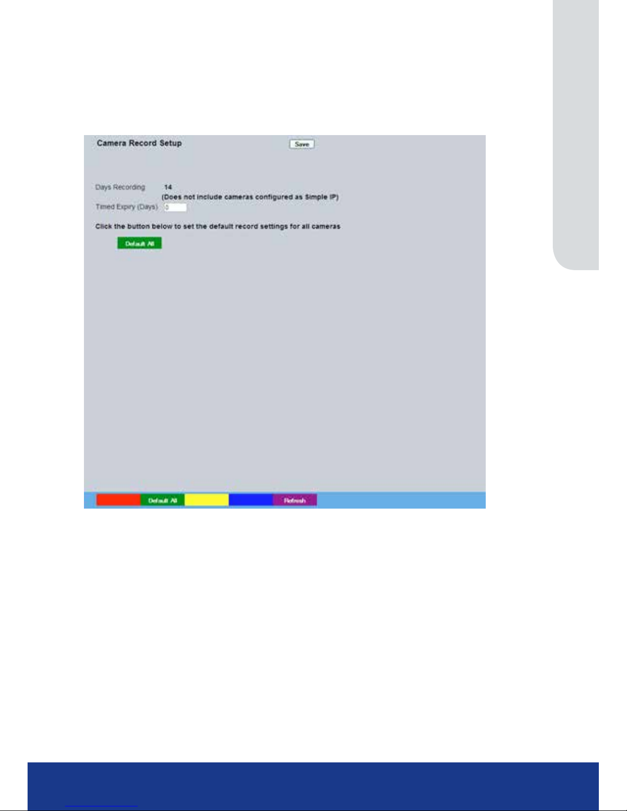
Default
The unit has a range of pre-dened congurations available. As standard the unit can record at 6pps
MPEG4 for up to 120 days (dependant on model). Alternatively the unit can be congured for 2pps
JPEG recording on each camera or for MultiMode operation (note that this will result in the record
duration being determined by the time period the unit is in alarm).
Days
Recording Displays the record duration possible using the current conguration.
Timed Expiry If required, all stored recorded video can be permanently deleted after a set
number of days. Set to ‘0’ to de-activate this function
Camera Settings Choose the rate of non alarm recording to be used from the range of preset
recording proles. Select from Normal Rate MPEG4 5pps, Normal Rate JPEG
1pps or MultiMode recording.
Record Duration/Enhance Quality The recording duration can be limited to a set number of days
(30,14 or 7); allowing the recording quality to be enhanced for a shorter storage
period.
Page 58
TransVu Compact
58
Prole Record
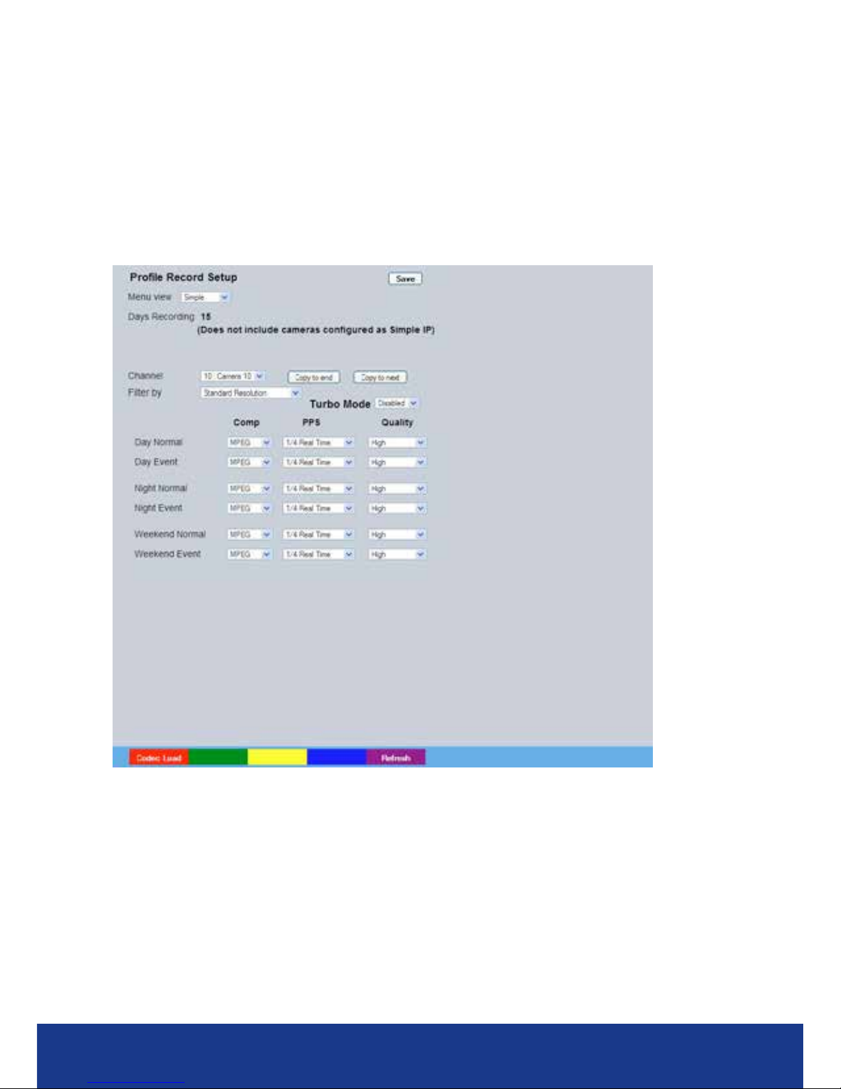
It is possible to set the unit recording conguration based on specic priorities.
The MultiMode recording
feature offers the ability to set different recording rates, resolutions and compression formats across
unset, set and override modes for each individual camera. By varying the quality, bit rate and le
size of recorded images, the MultiMode function enables the recording capabilities of the unit to
be greatly increased. The Prole record menu can be accessed in a Simple format or in Advanced
mode. The Advanced mode offering greater opportunities to dynamically edit individual cameras
recording capabilities.
Simple Record
Menu View Switch to the Advanced Prole Record menu.
Channel Enables selection of a specic camera for editing.
Copy To End Select to copy the current prole record settings to all camera channels.
Copy To Next Select to copy the current prole record settings to the next
camera channel.
Filter By Allows ltering by resolution (only standard resolution is
currently available).
Unset/Set/Override Normal Shows the recording prole used by the camera if no Timer Functions
are applied and the camera is operating under Normal (non Event)
conditions. Refer to the ‘Schedules’ section for further details.
Unset/Set/Override Event Shows the recording quality that will be used by the camera during an
Alarm or Event. Note that Set and Override schedules will be used only
when Timed Schedules are applied. Refer to the ‘Schedules’ section for
further details.
Page 59

www.transvu.co.uk
Configuration & Operation Guide
59
Comp Select image compression format (MPEG or JPEG).
PPS The accompanying dropdown list allows the number of frames captured
per second to be set.
The pictures per second (pps) option allows either 6, 5, 2, 1, 0.5, 0.25 or
0.1 pps to be recorded.
Pictures can also be recorded at ‘Real Time’ speed, ‘3/4 Real Time’ or ‘1/2
Real Time’.
To disable record, choose the ‘No Record’ option.
Select ‘User Dened’ to use settings established in the Advanced Prole
Record menu.
Quality The accompanying dropdown list allows the quality of recorded images to
be set. Select from Maximum, Very High, High, Medium, or Low. Select
User Dened to use settings established in the Advance Prole Record
menu.
Note: The higher the Quality setting, the greater the storage space used.
Page 60
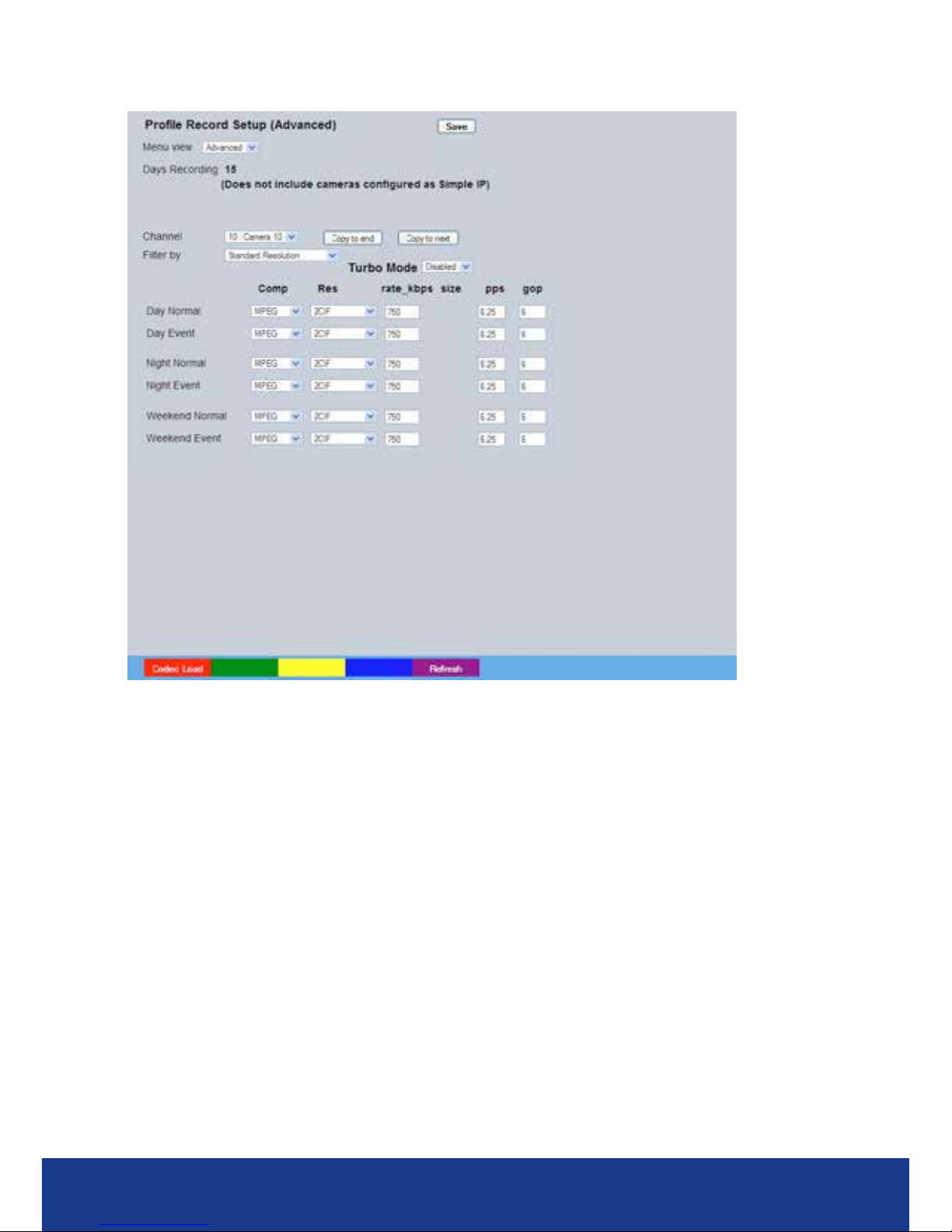
TransVu Compact
60
Advanced Record
Menu View Switch to the Simple Prole Record menu.
Note: When Advanced Record settings have been changed, it is not possible access the Simple Record
menu until the newly congured Advanced Record settings have been applied. To do this, open
the Record menu and select the ‘Save’ option. It will then be possible to return to the Prole
Record menu and access Simple Record.
Days Recording Displays the record duration possible using the current conguration.
Channel Enables selection of a specic camera for editing.
Copy To End Select to copy the current prole record settings to all
camera channels.
Copy To Next Select to copy the current prole record settings to the next
camera channel.
Filter By Allows ltering by resolution (only standard resolution is
currently available).
Unset/Set/Override Normal Shows the recording prole used by the camera if no Timed Schedules
are applied and the camera is operating under Normal (non Event)
conditions. Refer to ‘Schedule’ for further information.
Unset/Set/Override Event Shows the recording quality that will be used by the camera during an
Alarm or Event. Note that Set and Override schedules will be used
only when Timed Schedules are applied. Refer to ‘Schedule’ for further
information.
Note: Unset, Set and Override modes can be given more recognisable titles i.e. Day, Night, Weekend
via the Schedule menu (Record Settings->Schedule).
Comp Select image compression format (H264, MPEG or JPEG).
Res Select image resolution format (QCIF, CIF, 2CIF or 4CIF).
Page 61

www.transvu.co.uk
Configuration & Operation Guide
61
Rate_kbps If MPEG4 is selected, the gure entered here will be the bit rate allocated.
A higher bit rate will provide better quality. MPEG bit rates can be entered
within the range of 45-2500K bits/second.
Size If JPEG is selected, the gure entered here will be the size of the JPEG
transmitted (in Kbytes). JPEG le sizes can be congured within the range
of 5-45Kbytes.
PPS Select the number of pictures recorded per second.
GOP If using MPEG4 recording, select the number of images recorded within a GOP
(Group of Pictures). A GOP consists of an I-Frame (keyframe) and following P
frames.
Page 62
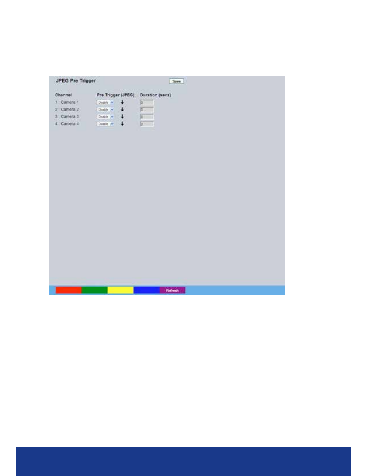
TransVu Compact
62
JPEG Pre Trigger
This menu enables conguration of the pre trigger feature (for cameras recording JPEG mode only).
When enabled, the pre-trigger feature will buffer and store alarm recording prior to an event trigger.
Only cameras set to record in JPEG will be displayed on this page.
Channel Enables selection of a specic camera for editing.
Pre-Trigger (JPEG) Enablng the Pre-Trigger feature will buffer and store alarm recording prior
to an event trigger (in JPEG format). It will use the maximum available
memory dependent on other cameras requirements of the buffer space.
Select ‘Enable’ to activate.
Note: It is recommended that the Pre-Alarm option in the ‘Alarm Settings-Zone Input’ menu be set to
the same value as the Pre-Trigger setting. This will ensure successful playback of high quality
Pre-Trigger images. High quality pre-trigger images will only playback properly if review (playback)
starts prior to the pre-trigger initiation.
Pre-Trigger Duration (secs)
The Pre-Trigger Duration is the maximum possible time that data will be
stored prior to an event trigger.
Page 63
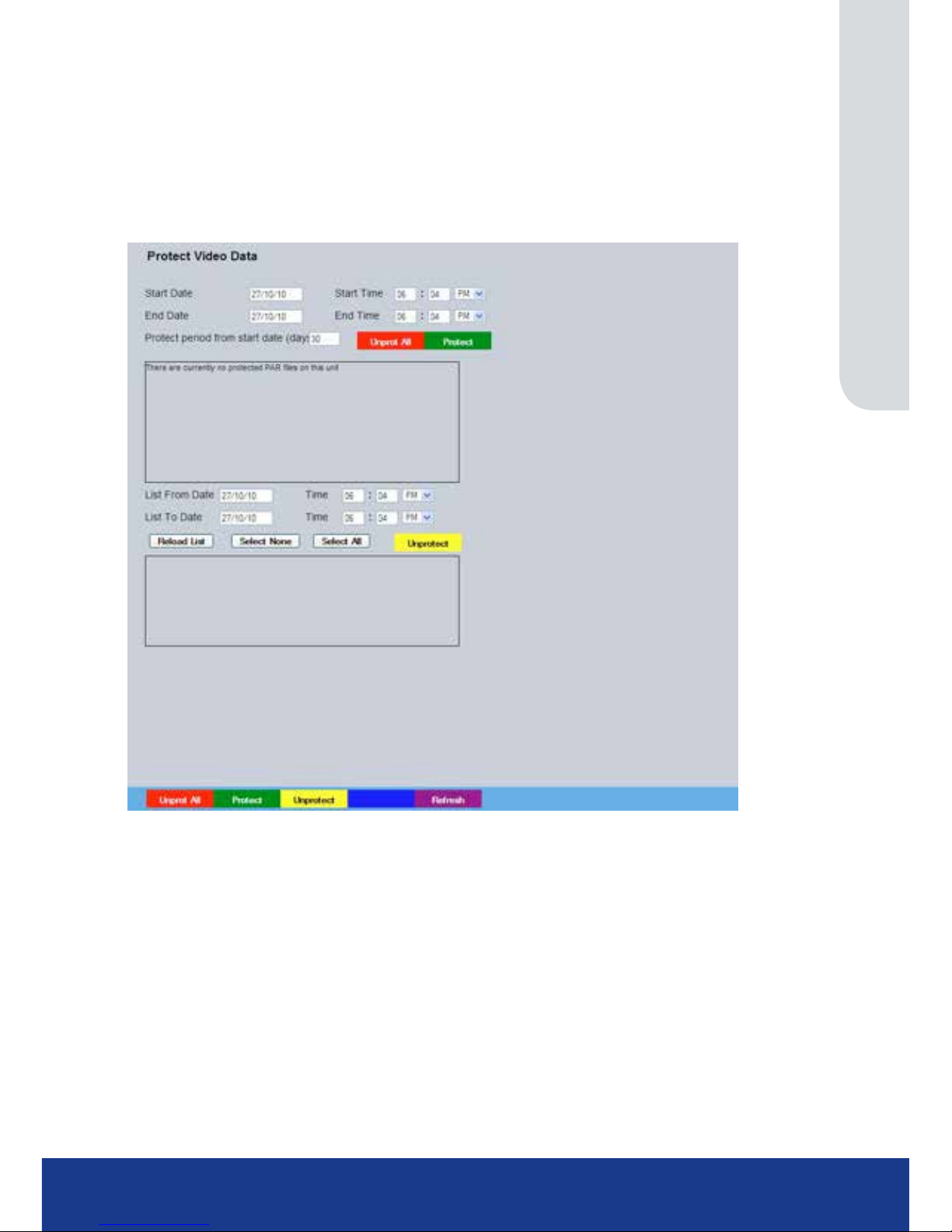
www.transvu.co.uk
Configuration & Operation Guide
63
Protect Video
This menu allows the unit to automatically protect and retain recorded data. Previously saved data
can also be unprotected. Enter a start and end time and select ‘Reload List’ . All saved video les
from the chosen time period will be shown in the upper textbox. These recorded ‘PAR’ les can then
be selected and protected via their accompanying checkboxes and the Protect option. Selected
video les can also be unprotected via the Unprotect option. The lower textbox provides a status
report detailing which video les have been protected/unprotected.
Start Date Enter a start date to protect video.
Start Time Enter a start time to protect video.
End Date Enter an end date to protect video.
End Time Enter an end time to protect video.
Protect Length (days) Enter the number of days that selected les will be protected for.
Protect (Green) Select this option to protect recorded video for the selected time period(s).
Unprotect All (Red) Select this option to unprotect all recorded video from the list.
List From Date/Time This dialog box allows a search to be made within the protected video list
starting from a specic Time and Date.
List To Date/Time This dialog box allows a search within the protected video list to conclude at a
specic Time and Date.
Reload List This will refresh the video list according to the selections made in the Start
Time/Date and End Time/Date dialog boxes.
Select None This de-selects all the available video les.
Select All This selects all the available video les.
Unprotect (Yellow) Select this option to unprotect recorded video for the selected
time period(s).
Page 64
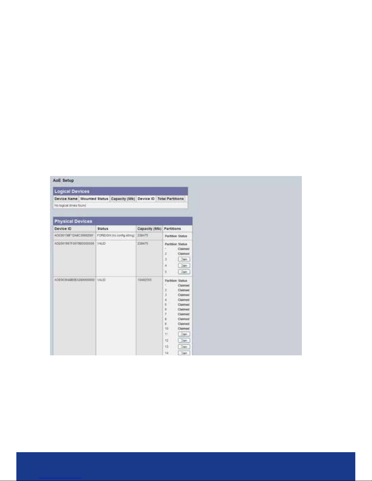
TransVu Compact
64
AoE Setup
This menu allows conguration of the units ATA over Ethernet (AoE) function. AoE is a network
protocol designed for simple high-performance access of storage devices over Ethernet networks.
Importantly the external storage device must be located on the same network as the unit. AoE does
not rely on network layers such as IP and TCP, making it non routable i.e. routers cannot be used
to forward a packet across disparate networks. AoE packets can only travel within a single local
Ethernet storage area network (adds a physical layer of security to the information). The stored
video can only be accessed by plugging directly into an ethernet socket in the same LAN as the
host. This means AoE cannot be accessed over the Internet or other IP networks, but makes AoE
more lightweight (with less load on the host), easier to implement, provides a layer of inherent
security, and offers higher performance.
Note: Refer to Viewer Menu->Copy Menu for guidance on exporting Event data via the unit’s
USB port.
IMPORTANT: An additional .ini le must be installed to make use of the AOE feature. Please
contact Dedicated Micros Technical support team (+ 44 (0) 845 600 9500) for
guidance
Note: Contact Dedicated Micros Technical support team (+ 44 (0) 845 600 9500) for details of
recommended AOE devices.
Logical Devices Connected AOE Devices - Any devices in this panel are being used by the unit
to store data. These can be freed by clicking on the Release button.
Physical Devices Available AOE Devices - Any devices in this panel are available on
the network.
They can be added to the storage capability of this unit by ‘claiming’ the storage,
using the ‘Claim’ button. Unavailable storage is listed as Owned. Claimed storage
capacity requires formatting before it can be used.
init cong string This button will remove failed or powered down devices that had previously been
recognised and are no longer available.
FDISK This button will format the whole device, erasing all data previously available on it
and setting it up for video data storage.
Refresh (Purple) Refreshes the current page.
Page 65

www.transvu.co.uk
Configuration & Operation Guide
65
Schedule
This menu allows the Timer Function names to be congured. The Timer Function enables the unit
to automatically be put into set/unset mode at specic times on specic days. This can help reduce
unnecessary alarm triggers. The mode will be set by the DVR that the camera is connected to.
When the unit is in Set or Unset mode, combine with different recording qualities and rates under
normal and alarm conditions for a high degree of control in a range of situations.
The Setup page allows conguration of the schedule including naming the modes of operation and
controlling when the unit changes between modes.
The RVRC page allows the Schedule to be changed to force a Day, Night or Weekend condition.
The Holiday & Weekend menu allows the unit to be automatically switched to Override mode for
individual days i.e. public holidays or during a weekend (or any dened period).
Page 66
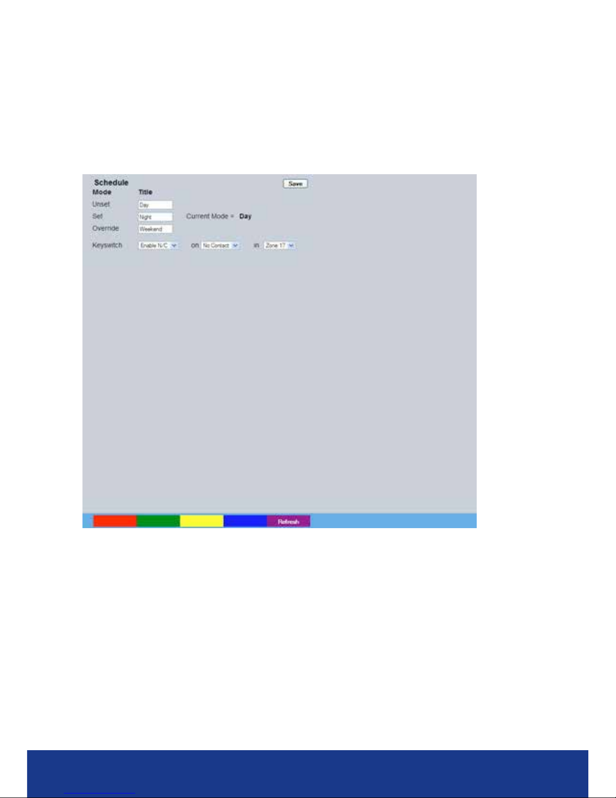
TransVu Compact
66
Setup
This menu allows the Schedule function to be congured. This enables the unit to automatically be
put into set/unset mode at specic times on specic days. This can help reduce unnecessary
alarm triggers.
Combining when the unit is in Set or Unset mode with different recording qualities and rates under
normal and alarm conditions gives a high degree of control in a range of situations.
Note: If Keyswitch is Enabled, the Day Time and Night Time options will not be displayed. The additional
Keyswitch options will instead be displayed.
Mode/Title Enables a name to be entered for Unset, Set and Override mode.
Note: Any changes to Mode titles here will affect the mode names displayed in the Prole Record, IP
Record and Zone Input menu pages.
Current Mode Shows the current timer mode according to the names entered in the Mode/Title
text boxes.
Day Time Enter the time (using the 24hr clock) when Unset mode will begin.
Night TIme Enter the time (using the 24hr clock) when Set mode will begin.
Keyswitch A Keyswitch can be used to switch the recording prole (Unset/Set).
Note: When the Keyswitch option is set to ‘Enabled’. It is necessary to save (or exit and return to) the
menu. The additional Keyswitch options will then be displayed.
Enable-N/O Select if the Keyswitch is to be normally open (UNSET). Then choose a contact
to be used in a specic zone as the Keyswitch.
Page 67
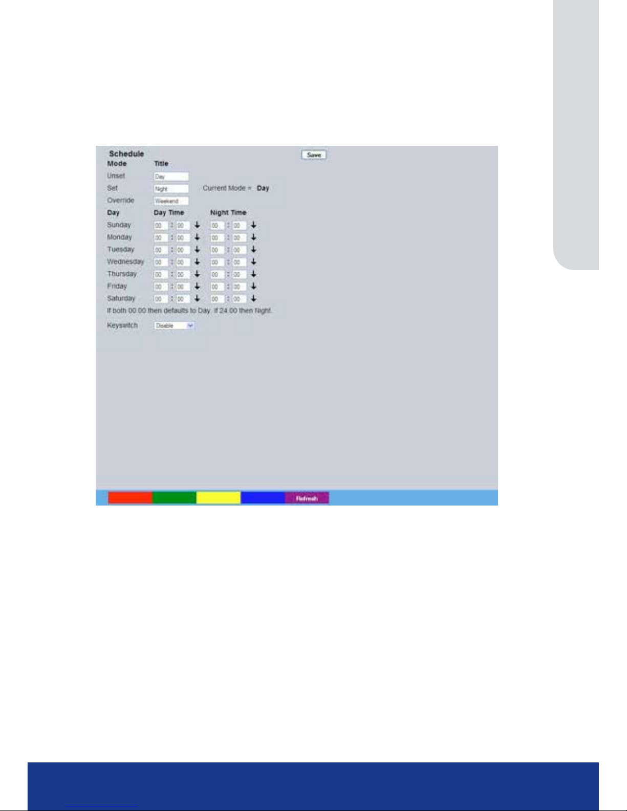
www.transvu.co.uk
Configuration & Operation Guide
67
Enable-N/C Select if the Keyswitch is to be normally closed (SET). Then choose a contact to
be used in a specic zone as the Keyswitch.
Enable EOL Select to congure the Keyswitch for EOL. The End Of Line (EOL) option
enables the Keyswitch to detect any changes in the electronic input resistance.
A change outside the expected values will result in a Tamper Alarm (short circuit
or open circuit) being detected and the system switching to alarm mode.
With Keyswitch Disabled
Day Species which Day of the week is being congured
NOTE: The next two descriptions utilise the standard name settings for the proles (SET, UNSET). If
these names have been changed on the ‘Schedule’ page, these menu options will display the user
congured names.
UNSET Time Species what time in format HH:MM the UNSET recording settings, congured
on the Prole Recording page, will become operational
SET Time Species what time in format HH:MM the SET recording settings, congured on
the Prole Recording page, will become operational
Note: The arrow button displayed next to each textbox allows settings to be replicated for those cameras
listed below. This will only affect the adjacent option i.e. Mode arrow will replicate the Mode setting
to all cameras below the clicked arrow.
Note: To disable one day, set both times to 00.00. To have the prole recording all 24 hours of a day, set
both times to 24.00.
Page 68
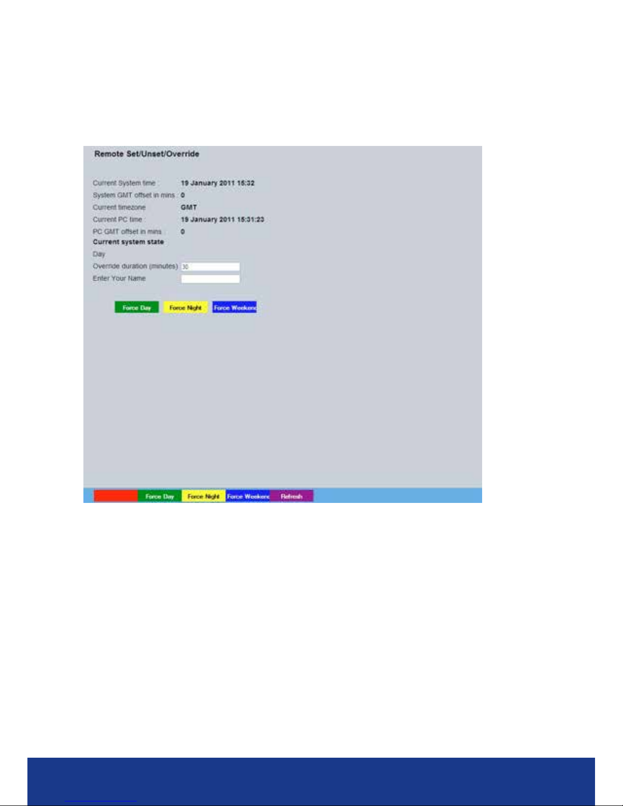
TransVu Compact
68
RVRC
This menu allows a user to temporarily switch the unit’s system state into set/unset/override mode.
The user will be required to enter their name and also the intended override duration. The action will
be logged.
Note: Refer to the Schedule menu for details of how to congure Set, Unset and Override modes:
Record Settings->Schedule.
Current System Time The unit’s current date and time information will be displayed. This will be
logged with any override action.
Current GMT Offset in mins Displays the offset from GMT
Current timezone Shows the current timezone the unit is in.
Current PC Time The current date and time information of the PC currently being used to view the
webpages will be displayed. This will be logged with any override action.
PC GMT offset in mins Displays the difference between the PC and GMT.
Current system state The current system state will be displayed i.e. Set, Unset
or Override.
Note: The system state names displayed here will depend on those entered via the Schedule menu:
Record Settings->Schedule.
Override duration (minutes) Enter a time period for the override procedure. After this time period, the
system state will return to that congured via the Schedule menu (for the current
time).
Enter Your Name Enter your recognised user name. This will be logged.
Force OVERRIDE (Blue) Select to switch to Override mode.
Page 69
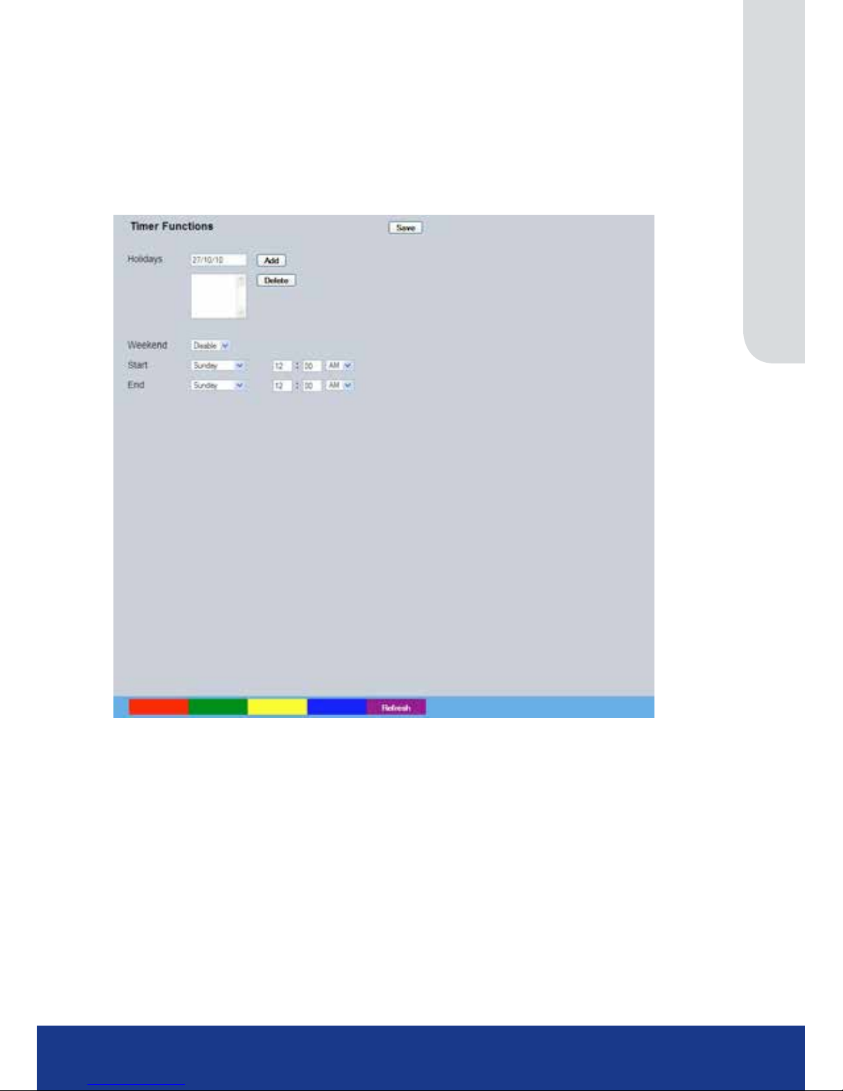
www.transvu.co.uk
Configuration & Operation Guide
69
Holiday & Weekend
This menu allows the unit to be automatically switched to Override mode for individual days i.e.
public holidays or during a weekend (or any dened period).
IMPORTANT: Holiday and Weekend settings cannot be entered when a Keyswitch has been
enabled in the Record Settings->Schedule menu.
Keyswitch Disabled
Holidays Enter a date and press the Add button. The date will be added to the Holiday
list. To delete, highlight and select Delete.
Weekends Select ‘Enable’ to activate the Weekend function. Set mode will now be active
for the dates outlined below.
Start Select a Start day and time for Weekend mode.
End Select an End day and time for Weekend mode.
Note: Weekend mode will remain activate each week until deselected.
Page 70

TransVu Compact
70
Alarm Settings
The Alarm Settings menus allow conguration of the unit’s alarm functionality. Individual alarm inputs
and alarm zones can be congured. Global relays can be activated and the Activity grid set up.
Refer to the individual menus for further details.
The Inputs page allows conguration of alarm channels. Up to 3 alarm channels are available.
The Zone Input page enables the conguration of alarm zones. Up to 32 separate alarm zones can
be created.
The Zone Actions page enables actions such as Go to Preset to be allocated to alarm zones. Zones
can also be associated with a specic camera. On receipt of an alarm, images from the associated
(primary) camera will automatically be displayed in the Viewer menu.
The Masked Camera Det(ection) page allows cameras to be enabled for ‘masked’ detection based
on a threshold contact value and dwell time.
The Data Logging page allows conguration of which changes in forces applied to the accelerometer
are logged.
The Accelerometer page allows set up and orientation of the unit’s 3-axis accelerometer (used for
measuring acceleration, braking, turning forces and vertical shock).
The Alarm Response page enables conguration of responses following an VMD/Activity
Detection trigger.
The Activity Setup page allowed activation and conguration of the Activity feature on all video
inputs. The Activity feature enables cameras to automatically detect any movement/changes within
the video scene. This can trigger a number of operations such as FTP alarm notication or an
increase in the recording rate.
The VMD Conguration page enables the unit’s VMD (Video Motion Detection) to be set-up. VMD
allows a camera to automatically detect if there is any movement/changes within specic areas of
the video scene.
The Global Actions page allows the onboard relay connections and global relay settings to be
congured.
Page 71
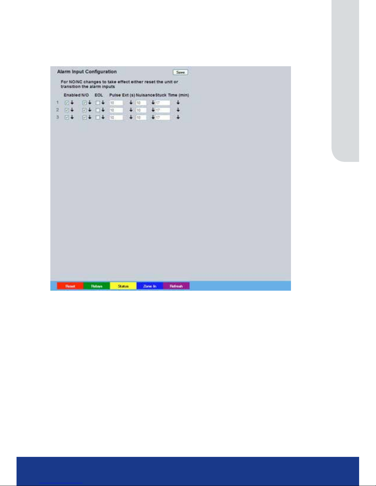
www.transvu.co.uk
Configuration & Operation Guide
71
Inputs
This menu allows conguration of the alarm settings, refer to ‘Installing the Unit’ for hardware
installation guidance.
Number This identies which input is being congured. The unit supports 3
on-board alarms.
Enabled Each input must be enabled to function. If the input is not enabled and an alarm
is received, the unit will not acknowledge the alarm.
N_O (Normally Open Contact)
N_O indicates the non-alarm state of the input. Tick the N_O checkbox to set
the corresponding input to Normally Open. The alarm will then trigger when
the input is closed (shorted). If left as Normally Closed (the default setting), the
alarm will trigger when the input is opened.
Note: If EOL alarms are to be used, this option should not be selected i.e. leave set as
Normally Closed.
EOL The End Of Line (EOL) option enables the inputs to detect any changes in the
electronic input resistance. A change outside the expected values will result in
a Tamper Alarm (short circuit or open circuit) being detected and the system
switching to alarm mode.
Pulse Ext (s) A pulse extension is used to prevent double triggers on a single alarm. The
pulse extension time starts on an alarm trigger. If that contact is triggered again
after the rst alarm has nished but within the pulse extension, the second
trigger will not restart the alarm, but will extend the current alarm duration. Enter
the time in seconds for this extension.
Page 72

TransVu Compact
72
Nuisance This is a repetitive detector value. When an alarm is received on the unit, it
will store the alarm time and monitor the number of times the same detector is
triggered within an hour period. If the detector is triggered the number of times
entered here, the unit will de-activate this detector from triggering an alarm for
an hour. The unit will continue to monitor the detector and check how many
times it is triggered during this period. If it is again triggered more than the
amount set in the nuisance counter, it will remain de-activated for another hour.
This will continue until the trigger value falls below the nuisance count setting.
To disable this feature, leave the setting as ‘0’.
Stuck Time (min) If any of the alarms/detectors are active for a period longer than specied here,
they will automatically be omitted. This time period is set in minutes.
Note: The arrow button displayed next to each textbox allows settings to be replicated for those cameras
listed below. This will only affect the adjacent option i.e. Enabled arrow will replicate the Enabled
setting to cameras below the clicked arrow.
Page 73
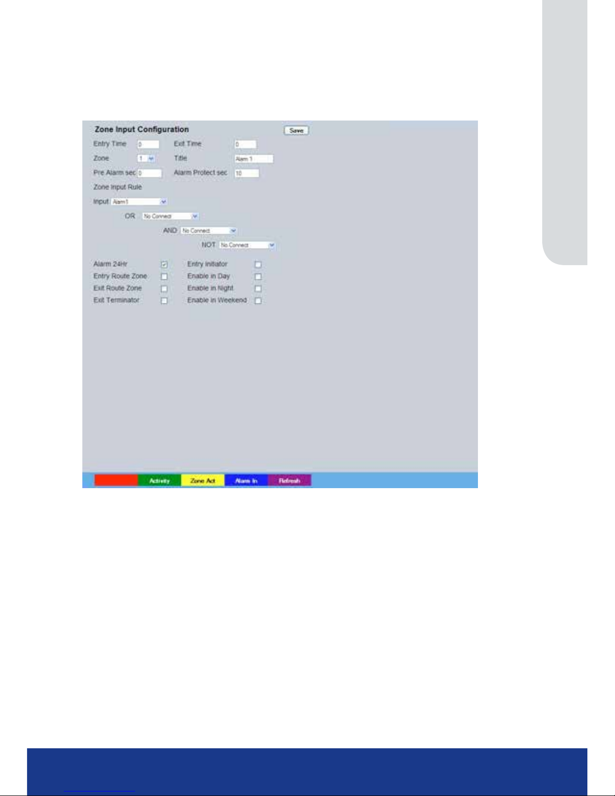
www.transvu.co.uk
Configuration & Operation Guide
73
Zone Input
This menu allows the conguration of established alarm zones. A single or multiple trigger can be
used to generate an alarm. It is possible to allocate up to 32 alarm zones to carry out a combination
of actions. Use these options in conjunction with the Zone Actions menu.
Entry timer This is the number of seconds allowed for the user to enter the zone and
disable the alarms. If the alarm is not disabled within this period the alarm will
be triggered.
Exit timer This is the number of seconds from the alarm being set within which the user
must exit the set zone. If the user is still within the zone after this time period the
alarm will be triggered.
Zone An alarm zone can be established to logically groups alarms and initiate actions
when an alarm is activated, there are 32 congurable zones.
Title This information is stored along with the relevant images in the database,
ensure this has relevance to the alarm zone.
Pre-Alarm sec This is the time period prior to the start of the alarm included with the alarm
recording for archive. These images will also be protected from being
overwritten.
Note: It is recommended that the Pre-Alarm option be set to the same value as the Pre-Trigger setting in
the “Prole Record“ menu. This will ensure successful playback of high quality Pre-Trigger images.
High quality pre-trigger images will only playback properly if review (playback) starts prior to the
pre-trigger initiation.
Alarm Duration sec This is the minimum time period in seconds (from the start of the alarm) that
is protected from being overwritten. This time will include the alarm trigger,
the pulse extension and any post alarm recording. It will not include pre-alarm
images.
Page 74

TransVu Compact
74
Zone Input Rule This determines which input(s) will trigger the zone alarm:
Input This sets an input or system function as the primary alarm trigger. Select from
Alarms 1-32, Activity 1-16, Preset 1-16, Disk Low, Disk Full, Panic, Archiving
Slow, Archiving Fault, Virtual 1-16, and Keyword Channel 1-32 (which will trigger
the Alarm if any or the 32 programmed keywords are detected on the selected
channel).
Zone OR Input The Zone OR Input identies an alternative input that can also be used to
trigger the zone alarm. This means an alarm trigger can be received on the
Zone Alarm Input or the Zone OR Input for the zone to be activated.
Zone AND Input
The Zone AND Input identies that an alarm trigger needs to be received on
both the Zone Alarm Input and the Zone AND Input for the zone to be activated
and the alarm action to the automatically initiated.
Zone NOT Input
The unit will only issue the alarm actions if the trigger is received on the zone
alarm input and NOT on the Zone input.
Alarm 24Hr This option can be enabled for alarms that do not require change at any time
and are to remain as programmed i.e. Panic Alarm. When this is selected, the
Set, Unset and Override options are disabled.
Entry Route Zone This creates deferred alarms along a specied route while the entry time is
active. This is in compliance with BS8418 (the British Standard for remote video
reporting centres). Diverting from the entry route during the countdown will
result in the alarm being triggered immediately. This allows staff entry without
triggering an alarm prior to switching the system to Set mode.
Exit route Zone This creates deferred alarms along a specied route while the exit time is
active. This is in compliance with BS8418 (the British Standard for remote
video reporting centres). Diverting from the exit route during the countdown will
result in the alarm being triggered immediately. This allows staff to exit without
triggering an alarm.
Exit Terminator This will trigger the exit timer if the system is set. A countdown timer will
automatically start when the alarm is activated and ensure the alarm system
is not activated by other specied alarm triggers for the Set time i.e. allowing a
Guard to exit a building.
Entry Initiator This will trigger the entry timer if the system is set. A countdown timer will
automatically start when the ‘primary’ alarm trigger i.e. front door, is actioned.
This ensures the alarm system is not activated by other specied alarm triggers
for the set time
Enable in Unset Each alarm can be congured to be active when the unit is in a specic
operation mode. Enable this for the zone alarm to be active in Unset operation
mode.
Enable in Set Each alarm can be congured to be active when the unit is in a specic
operation mode. Enable this for the zone alarm to be active in Set operation
mode.
Enable in Override Each alarm can be congured to be active when the unit is in a specic
operation mode. Enable this for the zone alarm to be active in Override
operation mode.
Note: Unset, Set and Override modes can be given more recognisable titles i.e. Day, Night, Weekend
via the Schedule menu (Record Settings->Schedule).
Page 75
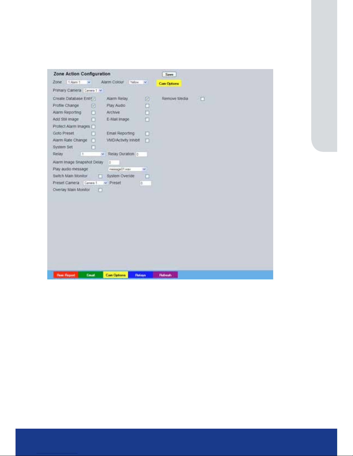
www.transvu.co.uk
Configuration & Operation Guide
75
Zone Actions
This menu allows actions to be allocated to individual alarm zones; Primary and Secondary cameras
can be allocated to the zone and actions undertaken following alarm activation. This page should be
congured in conjunction with the Zone Inputs menu.
Zone Select a zone (alarm) to congure.
Primary Camera This allows a camera to be assigned as the primary camera associated with the
Alarm Zone. The primary camera will be displayed when an alarm in this zone is
triggered.
Alarm Colour This displays the local alarm text in the selected colour and can be useful in
prioritising alarms. Options available are Red, Green, Blue, Yellow, Cyan and
Magenta.
Secondary Cameras This setting gives the facility to assign additional cameras to the zone. These
cameras will become part of the alarm sequence shown in the Viewer menus
when the alarm zone is triggered.
Create Database Entry An alarm activation will be added to the database. The zone title will be used as
part of the entry information.
Alarm Relay Select to trigger an alarm relay following zone activation. Select the specic
relay via the ‘Relay’ option.
Prole Change Select to enable the unit to switch from Normal to Event recording following
alarm zone activation.
Play Audio It is possible to play associated audio upon zone alarm activation.
Alarm Reporting This must be enabled to allow the unit to send an alarm notication to an
external destination i.e an RVRC reporting via NetVu ObserVer.
Archive Select to ensure the unit automatically downloads alarm images via an FTP
connection to an FTP server.
Page 76

TransVu Compact
76
Add Still Image This will record a still image of the trigger along with the standard recording.
This can then be sent on to an external destination.
Email Image If this option is selected, a JPEG will be added to the reporting email (if Email
Reporting is selected).
Protect alarm Images
Alarm images can automatically be protected from
being overwritten
.
Goto Preset It is possible to action a camera to automatically be sent to a preset position
when an alarm is triggered.
Email Reporting The unit can send an email when an alarm is detected, refer to ‘Network-E-mail’
for more information.
Alarm Rate Change Select to change to the alarm mode recording rate on zone action.
VMD/Activity Inhibit Select to inhibit (ignore) the VMD/Activity detection feature. Refer to ‘Activity
Setup’ for more information.
System Set Select to change to the ‘Set’ mode recording rate on zone action.
Preset Camera The preset camera is the camera which will be sent to a designated preset
position upon alarm activation.
Preset Enter the preset position number for the selected camera here, refer to ‘Unit
Operation-PTZ Program’ for more information on establishing camera preset
positions.
Relay Select an onboard or external relay to automatically close on receipt of an
alarm.
Relay Duration Enter (in seconds) how long the relay is to remain closed.
Alarm Image Snapshot Delay This gure allows a delay to be introduced before an alarm snapshot is
taken. This is used when the alarm relates to a PTZ camera which has to travel
to a preset position.
System Overide Select to change to the ‘Overide’ mode recording rate on
zone action.
Play Audio Message Following a Zone alarm trigger, a specic audio message
can be played.
IMPORTANT: Audio messages must be uploaded to the unit in mono 8k wav format only.
The following naming convention must be used: messageXX.wav
i.e. message00.wav, message01.wav etc.
An FTP client should be used to place the wav les in the following folder:
\mdd0\messages folder .
Page 77
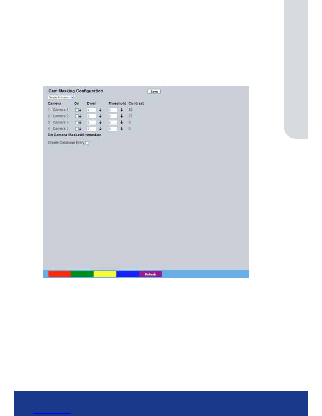
www.transvu.co.uk
Configuration & Operation Guide
77
Masked Cam Det
The unit has the capability to identify if a video input has been covered (by hand, spray paint, etc.)
to prevent video images being viewed and recorded. The Camera Masking option identies normal
levels of contrast and uses them as a base line. It then compares these against a user dened
minimum contrast level. If the video input goes below this user dened level an event is generated
on the unit.
Simple Activation
Simple Activation Select Zone Activation
Camera Displays the camera number and camera title as congured on the Camera
Setup page.
On Enables or disables the feature on the camera.
Dwell This is the delay the unit will wait before declaring the camera is masked.
Threshold Denes the threshold the system uses to dene that a camera is masked.
Contrast Denes the contrast threshold the system uses to dene that a camera is
masked. Different cameras have different characteristics, it will be necessary to
adjust this gure to avoid false alarms.
On Camera Masked/Unmasked There is only the option to add an entry into the database in
Simple Activation. Select Zone Activation for more options.
Page 78
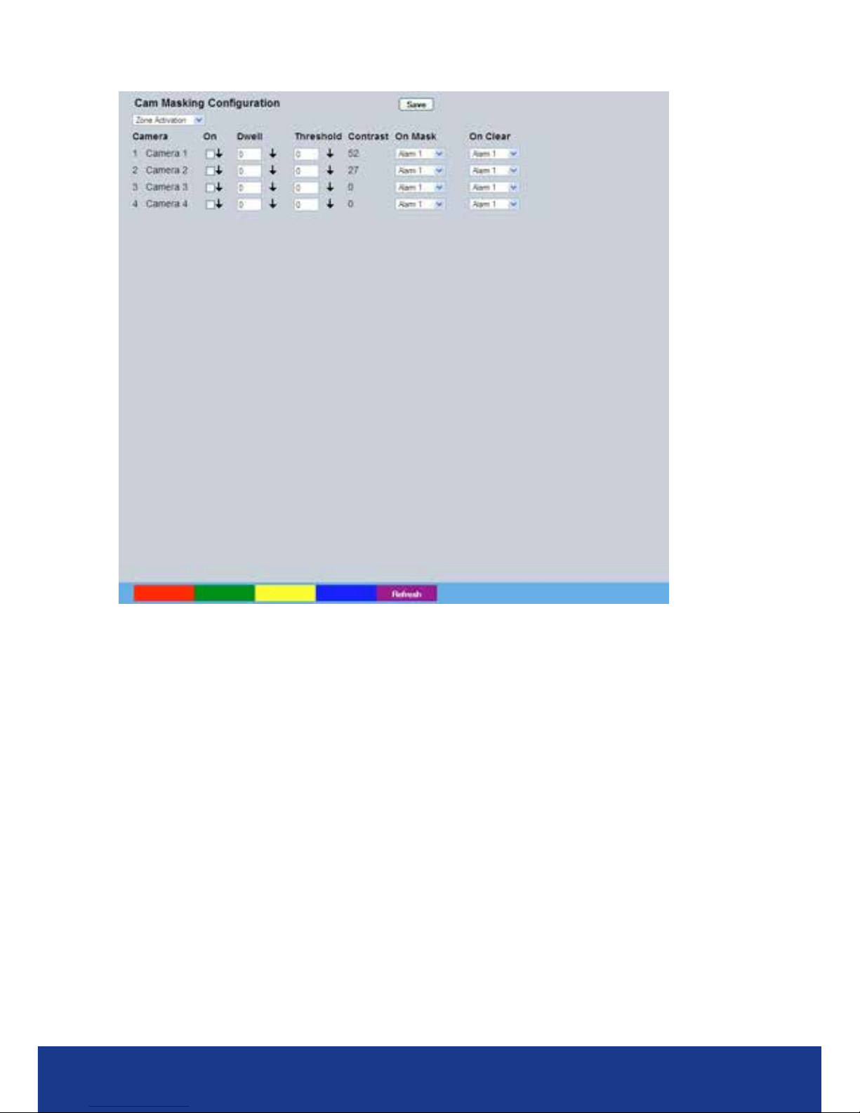
TransVu Compact
78
Zone Activation
On Mask Denes the Zone trigger that will be activated when the view is masked.
On Clear Denes the Zone trigger that will be activated when the view is unmasked.
Page 79
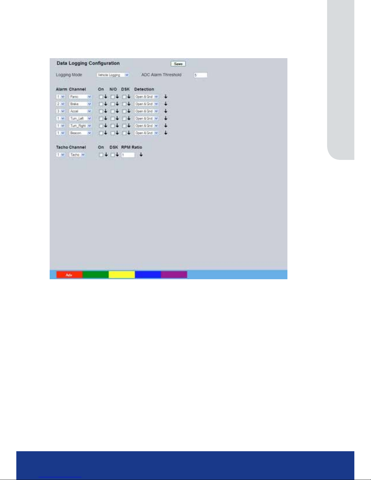
www.transvu.co.uk
Configuration & Operation Guide
79
Data Logging
The unit can log changes in the forces applied to the accelerometer.
Logging Mode Various logging modes are available. Select either ‘Vehicle Logging’, ‘Vehicle
Analysis’ or ‘Simulated Logging’ to display default settings for each specic
logging task. Selecting ‘User Dened’ allows the user to congure parameters
as required.
Alarm Select the alarm input to be logged
Channel Select the Data Channel to be logged;, in Vehicle Logging, the options are
Panic, Brake, Accel, Turn_Left, Turn_Right, Beacon or Siren.
On Enable or disable the feature.
N/O Select if the alarm is normally open or closed.
DSK Log the alarm data to disk
Detection Select the type of Voltage detection to be logged
Tacho Select the Tacho/Speedo channel.
Channel This can monitor the Tacho or the Speed.
On Enable or disable the feature.
DSK Log the Tacho data to disk
RPM Ratio Allows the reading to be multiplied up to give an easily understandable display.
Page 80
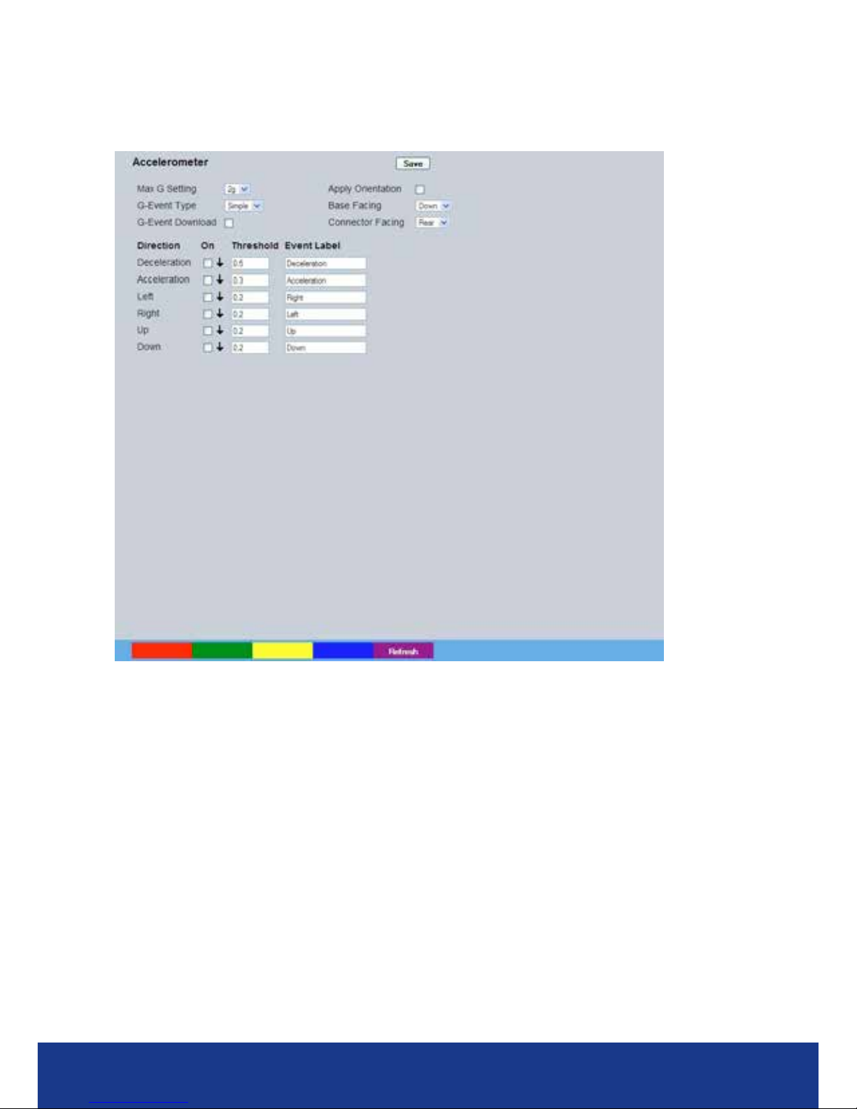
TransVu Compact
80
Accelerometer
The unit is tted with a 3-axis accelerometer for measuring Acceleration/Braking, Turning Forces and
Vertical Shock (speed bumps, kerb strikes etc.)
Max G Setting Select from 2g or 8g (defaut setting is 2g).
Apply Orientatiion Enable orientation settings (entered below).
G-Events Type Select to download either all ‘Simple’ G-Event data or by ‘Zone’.
Base Facing Select where the base of the unit is position i.e. if the unit’s base is facing the
oorm, select ‘Down’.
G-Event Download Select to auto download G-Event data depending on the criteria selected in the
‘G-Event Type’ option.
Connector Facing Select which direction the units connection ports are facing.
Deceleration Enter the g limit for a deceleration event to be logged. For example an
emergency stop will register approx 0.7g plus.
Acceleration Enter the g limit for a acceleration event to be logged. For example a fast saloon
car may register approx 0.5g.
Left Enter the g limit for a tight left turn event to be logged. For example a fast
saloon car may register approx 0.6g on such a manoeuvre.
Right Enter the g limit for a tight right turn event to be logged. For example a fast
saloon car may register approx 0.6g on such a manoeuvre.
Up Enter the g limit for an Up direction ‘shock’ to logged. Such incidents can reach
and exceed 2g.
Down Enter the g limit for a Down direction ‘shock’ to logged. Such incidents can
reach and exceed 2g
On Select to turn the relevant g limit event ‘On’.
Page 81

www.transvu.co.uk
Configuration & Operation Guide
81
Threshold The limit above which the force in question will need to exceed to trigger any
one event.
Event Limit Enter a name to appear in the database when responding to a
G event.
Page 82
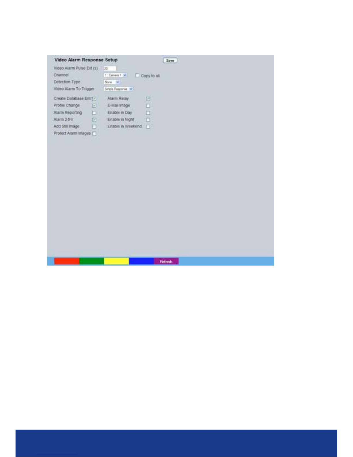
TransVu Compact
82
Alarm Response Setup
This menu enables response conguration following activity trigger on a selected camera channel.
VMD Pulse Ext The pulse extension extends the trigger period to avoid double triggers of VMD
occurring, i.e. If a second incident of VMD is received, after the rst alarm is
nished but within this period, the unit will not create a new event.
Channel Select the camera input for conguration from the drop down list.
Copy To All Select to copy the current Activity Response settings to all
camera channels.
Detection Type Each camera input can be congured for either ‘VMD’ or ‘Activity’ detection. To
assign no detection settings to the camera, select ‘None’
Note: Whichever Detection option is selected here, will result in the camera channel being only
available
for editing in the relevant conguration menu i.e. if Activity is selected for Channel
1; this channel can
only be edited for Detection in the Activity Setup menu and not the VMD Conguration menu.
Activity To Trigger Following Activity activation, select ‘Simple Response’ to trigger specic chosen
responses from the options detailed below. Select ‘Zone’ to apply the Zone
Input rules as congured in the Zone Input menu. Refer to ‘Zone Input’ for more
information.
Note: When Activity to Trigger is set to ‘Zone’; the options detailed below are unavailable.
Create Database Entry When selected, an alarm entry will be added to the
Event database.
Prole Change Select to enable the unit to switch from Normal to Event recording following
alarm activation.
Alarm Reporting This must be enabled for the unit to automatically connect
on alarm.
Page 83

www.transvu.co.uk
Configuration & Operation Guide
83
Alarm 24Hr This will ensure that Activity Detection is permanently enabled on this camera
channel.
Add Still Image This will record a still image of the trigger along with the standard recording.
This can then be sent on to an external destination.
Protect Alarm Images Select to automatically protect alarm images from
being overwritten.
Alarm Relay Select to trigger an alarm relay following zone activation. Select the specic
relay via the ‘Relay’ option.
Email Image If this option is selected, a JPEG will be added to the reporting email (if Email
Reporting is selected).
Enable in Unset This will enable Activity Detection when the unit is in Unset
operation mode.
Enable in Set This will enable Activity Detection when the unit is in Set
operation mode.
Enable in Override This will enable Activity Detection when the unit is in Override operation mode.
Note: Unset, Set and Override modes can be given more recognisable titles i.e. Day, Night, Weekend
via the Schedule menu (Record Settings->Schedule).
Page 84
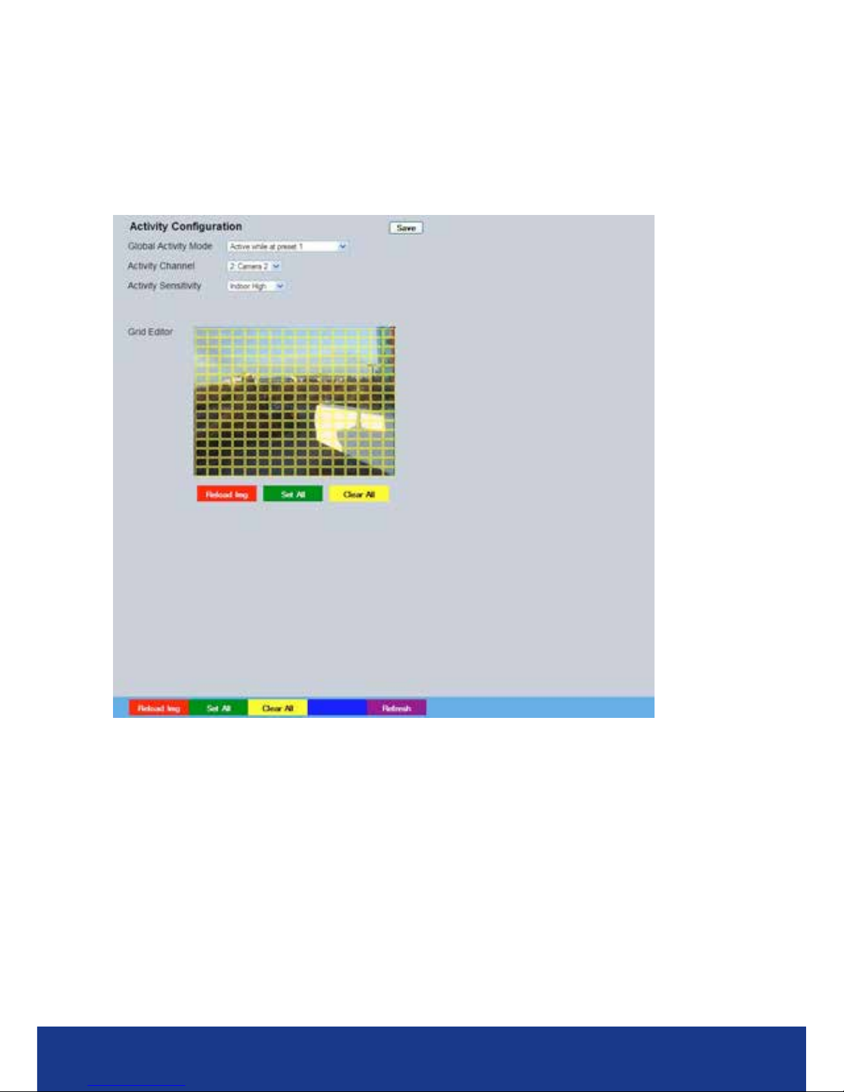
TransVu Compact
84
Activity Setup
The unit supports Activity Detection on all video inputs. It enables cameras to automatically detect
any movement/changes within the video scene; this can trigger a number of operations such as FTP
alarm notication and an increase in recording rate.
A still image of the selected camera will be shown in the Grid Editor screen. To establish an Activity
zone, edit the cells displayed across the image.
This option should be used in conjunction with the Zone Inputs and Zone Actions menus.
Global Activity Mode Three options are available for Activity activation (specically in relation to a
PTZ camera).
Selecting ‘Active while at Preset 1’ will result in Activity mode
functioning only when the camera is at preset position 1. Select ‘Active while
camera not in motion’ for Activity mode to function only when the camera is still.
Select ‘Always Active’ for Activity mode to be in constant operation.
Activity Channel This is a drop down list of the video inputs on the unit, selecting an input will
display images from the corresponding video source.
Edit Action Select ‘Invert’ to change the current grid state i.e. Clear to Set. Select ‘Clear’ to
remove grids or select ‘Set’ to add grids.
Activity Sensitivity This option allows the sensitivity setting to be established for the activity grid
being congured. There are ve settings to choose from: Indoor High, Indoor
Low, Outdoor High, Outdoor Low, Very Low.
Page 85

www.transvu.co.uk
Configuration & Operation Guide
85
Grid Editor Use the Grid Editor by placing cells in areas of the camera view where
movement will trigger an alarm. To enter cells navigate across the image via
the Directional buttons of the I.R Remote Control). If viewing on a local monitor
place a cell by pressing the OK button. If viewing via the webpages, use the
mouse to navigate across the image, use the left mouse button to
place a cell.
Reload Img (Red) This option will update the still image displayed in the Grid Editor.
Set All (Green) This option will insert a default square of 16 x 16 cells across the displayed
video image.
Clear All (Yellow) This option will clear all entered cells.
Page 86
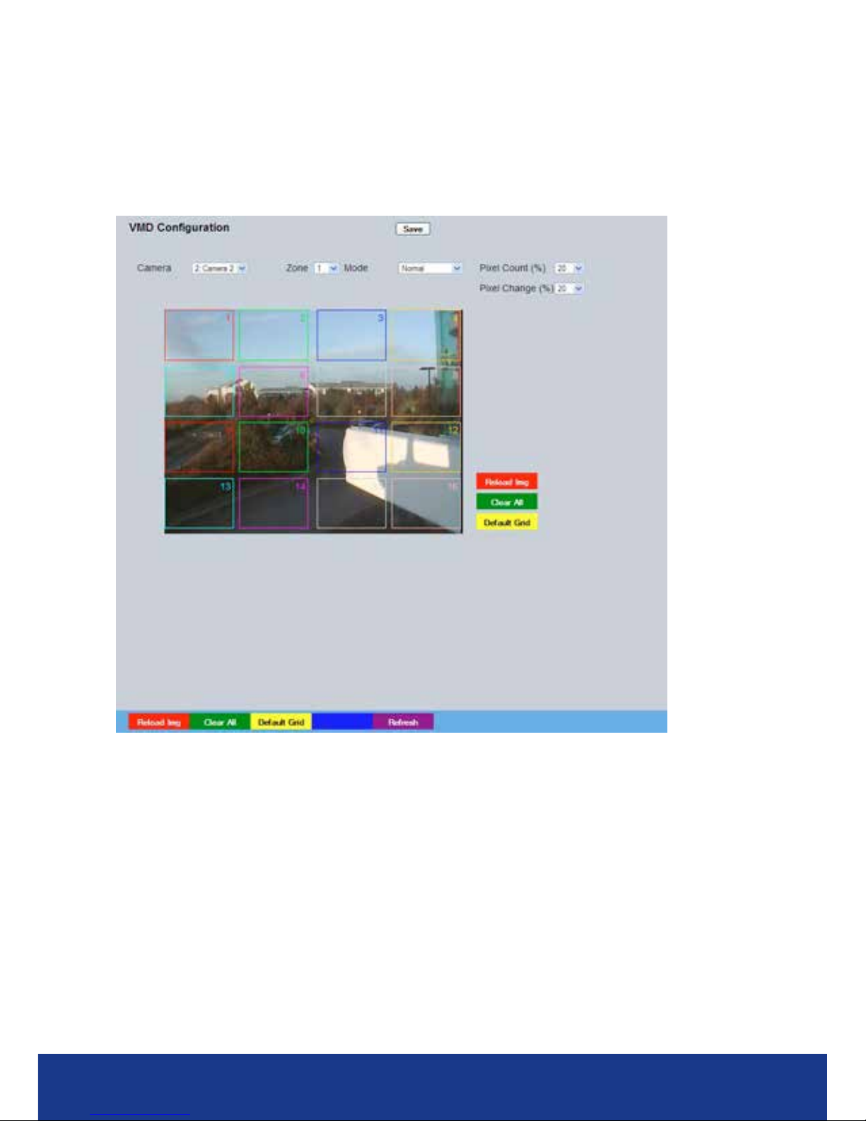
TransVu Compact
86
VMD Conguration
The unit supports VMD (Video Motion Detection) on all video inputs and allows cameras to
automatically detect if there is any movement/changes within the video scene.
Note: Video Motion Detection enables a greater degree of control over detection settings and
conguration than the Activity Setup function. Each of the 16 VMD Zones can be directly sized and
congured to suit specic requirements. VMD can only be accessed and congured remotely via
the webpages.
Camera This is a drop down list of the video inputs on the unit, selecting one of the
inputs will display the corresponding video source. Ensure this corresponds with
the selected Channel.
Zone There are 16 VMD zones within the image that can be individually congured,
select the zone from the drop down list.
A selected zone can be re-sized by clicking the mouse button (use the USB
mouse if viewing on a local monitor) and then moving and clicking the mouse
again. A rectangle will then be displayed based on these two selected points.
Page 87

www.transvu.co.uk
Configuration & Operation Guide
87
Mode The zone mode identies when the reference image is taken for triggering VMD.
The options are:
Normal - The reference image is updated approx every
second. This will only allow small changes in the
scene without triggering
Last trigger - The reference image is only updated when the VMD
is triggered and is best used under controlled lighting,
i.e. so there are no false triggers due to ambient light
changes.
Static - The reference image is collected on startup and is
never updated. This would be used in ‘sterile’ areas
where there are no changes expected.
Zone disabled - This will disable the zone mode.
Pixel Count (%) This value is set as a percentage and equates to the percentage of pixels in the
selected zone that must change for the VMD event to be triggered. The default
setting is 20%.
Pixel Change (%) This setting is a percentage value of the overall change required in the
grayscale to be included in the pixel count. The percentage change is dened
over the complete range of black to white, a 100% pixel change would be from
black to peak white. The default setting is 20%.
Reload Image (Red) This will update the reference image to the latest view during
set up.
Clear All (Green) Removes all dened zones from the image.
Default Grid (Yellow) Displays the default 16 zone grid across the whole image.
Page 88
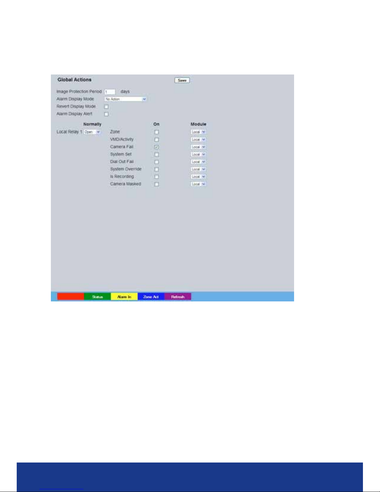
TransVu Compact
88
Global Actions
This menu allows conguration of the default relay actions supported on the unit.
The unit supports one onboard relay connect
ion and global relay settings. This global relay can be
trigge
red under specic conditions i.e. on receipt of any alarm or notication of Activity
Detection
.
Image Protection Period Select a time period (in days) that images associated with an alarm will be
protected from deletion.
Alarm Display Mode When a relay has been triggered, the primary camera associated with that relay
can immediately be displayed on the local monitor. Select ‘Jump To Primary
Camera’ from the drop down list to activate this function.
Revert Display Mode Enable this setting to make the unit return to the view displayed before the
alarm activation once the alarm has ended.
Alarm Display Alert Enable this setting to display an alarm text alert in the colour specied in ‘Alarm
Colour’ in the Zone Actions Menu.
Normally Select whether the normal state of the relay contact should be Open
or Closed.
On Select to enable detection of the accompanying condition. Options available
are; VMD/Activity, Camera Fail, System Set, Dial Out, System Override,
Camera Masked, Is Recording, Not Recording and HDD problem.
Contact Species which Relay will be triggered when the associated alarm
is received.
Page 89

www.transvu.co.uk
Configuration & Operation Guide
89
Network Settings
The Network Settings menus allow conguration of the unit’s network functionality. Key network
settings can be established such as ‘xing’ the unit’s IP address and maximum transmission rate.
E-mail, remote reporting on alarm and FTP download can also be congured. Refer to the individual
menus for further details.
The Network Settings page allows conguration of the unit’s network connections such as the name
assigned to the unit and its IP address.
The Live Trans(mission) page enables JPEG and MPEG proles to be created for transmitting
images via a High, Medium or Low quality network connections to any viewing software or to
another unit using this one as an IP source.
The Multicast page allows recordings from the unit’s camera inputs to be forwarded to a port
address; enabling multiple viewers to view live data using a suitable media player without the need
to directly connect to the unit.
The Email page allows conguration of the Email feature. The unit can automatically transmit an
e-mail to an SMTP Server following an event i.e. on receipt of an alarm or a camera failure notice.
The Remote Reporting page allows a Remote Video Receiving Centre’s (RVRC) conguration
details to be entered. The RVRC will then be contacted following a selected event occurring i.e.
reported alarm or camera failure.
The Web Cam page congures images from one camera input to be sent to a web server at a preset
interval for display on a web page.
The FTP Download page allows data to be archived to a central FTP server. This could be on receipt
of an alarm, Activity activation or at a scheduled time to back-up recorded video.
This Firewall page allows the user to block access to the unit via specic network port(s).
Page 90
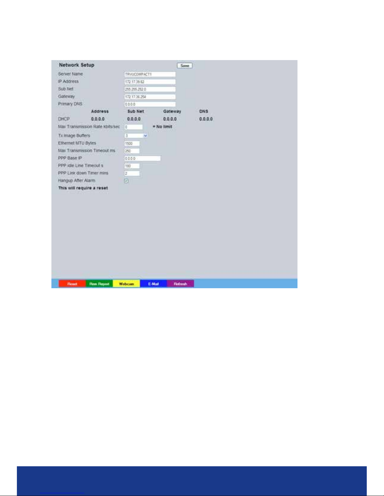
TransVu Compact
90
Network
This menu allows additional network settings to be congured if required.
Server Name This eld can be edited to allocate a name to the unit. This would be used
if accessing the unit via a Domain Name Server (DNS).
IP Address
This is the IP address allocated to the unit.
Sub Net This is the subnet of the network were the unit is located.
Gateway This is the IP address of the default gateway (router).
Primary DNS
This is the primary DNS server IP address for applications utilising domain names.
Max Transmission Rate Shows the maximum transmission speed for the network type.
Tx Image Buffers This is used in order to improve the picture delivery over Ethernet when using a
slow connection i.e. 256Kbps. A buffer setting of 1,2 or 3 is available.
Ethernet MTU bytes This is the maximum transmit unit for the Ethernet packet. The MTU is the
largest physical packet size measured in bytes that the network can transmit. By
default this gure is set to 1500bytes.
Mx Transmission Timeout ms
This is the time (in milliseconds) the unit will wait to re-send a packet if an
acknowledgement is not received.
PPP Base IP Base address for the PPP port
PPP Idle Line Timeout s This is the time (in seconds) the unit will wait before disconnecting
the PPP (Point to Point Protocol) link if data has not been
transmitted or received.
PPP Link Down Timer mins
If for any reason the PPP connection is lost, this is the time (in minutes) before
the unit will be forced to drop the PPP connection.
Hangup After Alarm Select to close the network connection following transmission of alarm data.
Reset (Red) Before any changes made to the Network settings can take effect, the unit must
be reset.
Page 91
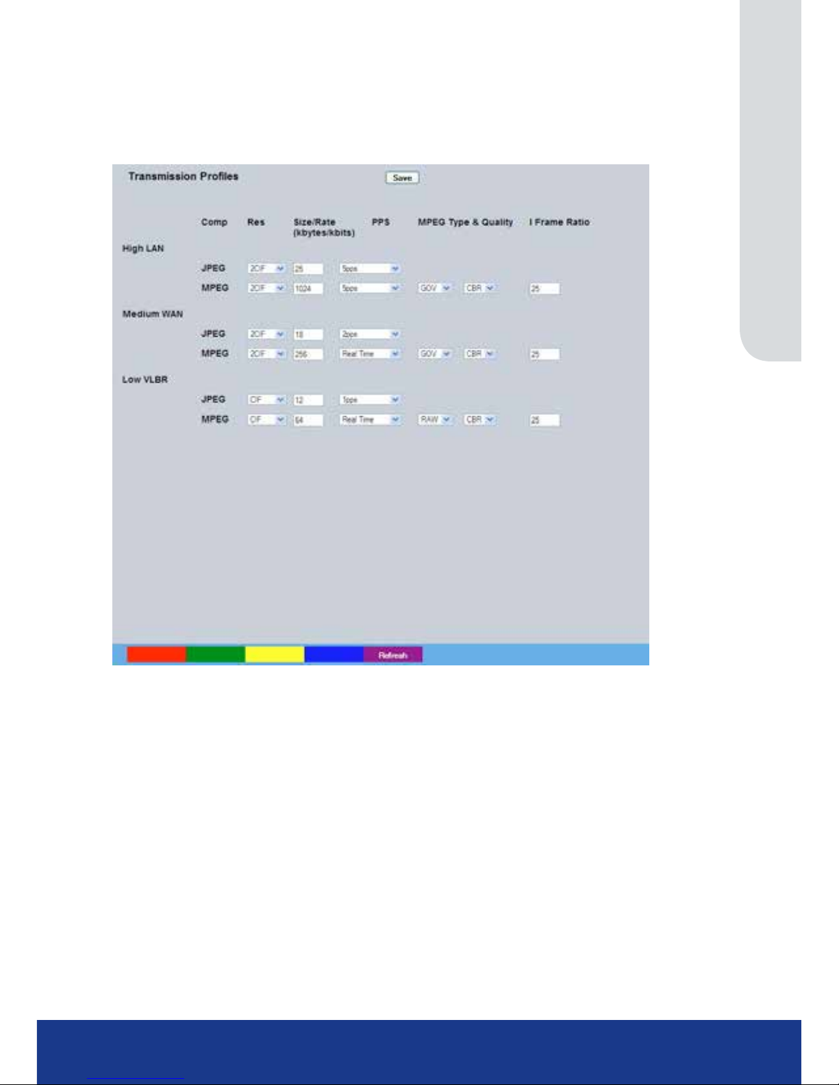
www.transvu.co.uk
Configuration & Operation Guide
91
Live Trans
The unit transmits live images using JPEG or MPEG formats.
The NetVu Connected remote viewing software will use the settings congured on this page as the
defaults for JPEG & MPEG; High, Medium and Low settings.
High LAN/Medium WAN/Low VLBR This shows the transmission settings congured for a High quality LAN
(Local Area Network) connection, Medium quality WAN (Wide Area Network)
connection or a Low quality VLBR (Very Low Bit Rate connection).
Comp Settings can be established for JPEG and MPEG compression
.
Res
For MPEG and JPEG transmission, select image resolution settings (4CIF,
2CIF, CIF or QCIF).
Size_rate For JPEG, the gure entered will be the size of the JPEG transmitted (in
Kbytes). For MPEG4 the gure will be the bit rate allocated. A higher rate will
provide better quality picture display. JPEG le sizes can be congured in the
range of 5-45Kbytes and MPEG bit rates in the range of 45-2500Kbits/second.
PPS This shows the number of pictures transmitted per second.
For JPEG, the actual
images transmitted will depend on the bandwith of the link, increasing the
pictures sent per millisecond may introduce time lag if bandwith is not sufcient.
On MPEG transmission, increasing the pictures sent will also reduce the quality
of the images (as more images are transmitted for the dened bit rate).
MPEG Type Select whether transmitted MPEG4 images are sent as RAW data or in GOV (Group
of Video) format. RAW mode transmits a single I frame and then a sequence of
P frames (until a change in transmission is detected). GOV mode sends I and P
frames in a standard format i.e. I to P frame
ratio as set by the I Frame Ration option.
Page 92

TransVu Compact
92
MPEG Quality The Quality of the MPEG data transmission can be set from CBR (Constant Bit
Rate) to High 32. A higher quality setting may result in a lower transfer speed.
I Frame Ratio Select the ration of I Frames recorded between each P Frame.
Note: An MPEG I-frame is considerably larger than a P-frame.Therefore the higher the IP ratio, the
higher the disk space required to store recorded images.
Page 93
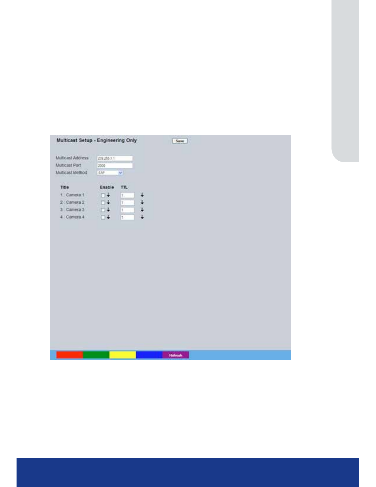
www.transvu.co.uk
Configuration & Operation Guide
93
Multicast Setup
The Multicast page allows recordings from the unit’s camera input to be forwarded to a port address;
enabling multiple viewers to view live data using a suitable media player without the need to directly
connect to the unit. In multi viewing scenarios, the demands on the unit are signicantly reduced;
improving overall performance.
This system has been validated using the ‘Videolan VLC media player for MS Windows.
The Videolan VLC media player can be downloaded free of charge from:
www.videolan.org/vlc/download-windows.html
Please refer to Appendix E for guidance on conguring the Videolan VLC media player.
Note: Multicast can only used for live viewing, requests for stored images and events will still need to be
made via the Viewer menu.
Multicast Address Assign a unique IP address. This address is not assigned to any ‘physical’
unit. The VLC program will use this address (when congured to do so) as
its multicast group and access any broadcast images via the congured port
address (see below).
If there are multiple units using multicast, each one must have a unique IP
address.
Multicast port Following conguration of the IP address, congure the port address. The
address will default to 1234, .
Multicast Method Select the multicast forwarding method. Select from ‘SAP’ (to use session
announcement protocol operation), ‘HTTP’ (to use using cgi control operation)
or ‘SAP+HTTP’ (both methods used simultaneously)
Enable Tick this option to enable multicast.
Page 94

TransVu Compact
94
TTL (Time to Live) This option can be congured to limit which users can access the images. Enter
one of the following numbers:
0 - restricts video to the same host
1 - restricts video to the same subnet
32 - restricts video to the same site
64 - restricts video to the same region
128 - restricts video to the same continent
255 - is unrestricted in scope
Page 95
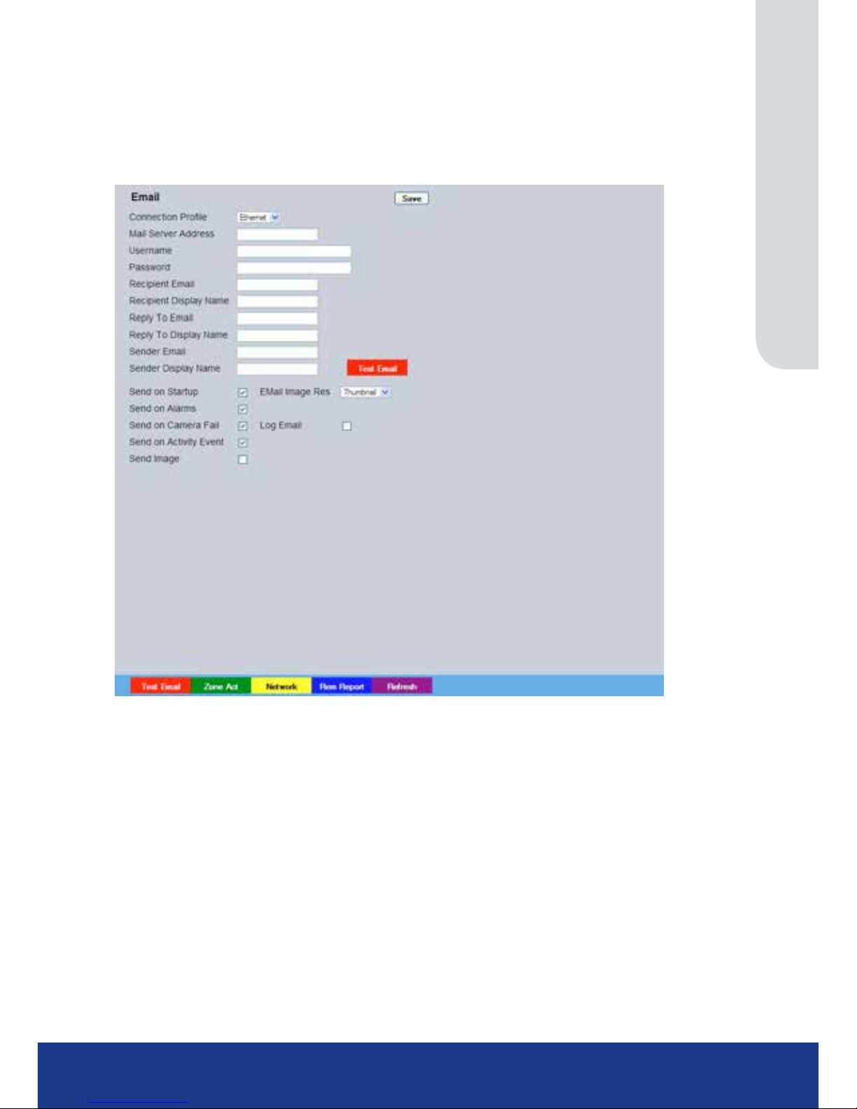
www.transvu.co.uk
Configuration & Operation Guide
95
E Mail
The unit can automatically transmit an e-mail to an SMTP Server under numerous conditions i.e. on
start up, on receipt of an alarm, camera failure etc. This allows the unit to be installed in unmanned
applications where a Remote Video Response Centre (or Manager etc.) would be notied by e-mail
if any of these conditions occur.
Connection Prole It is possible for the e-mail to be transmitted via the Ethernet network or dial up
connection (PPP ‘Point to Point Protocol’). This setting presumes that a modem
has been connected or congured and the unit is connected to a LAN or WAN
and allocated a valid IP address.
Mail Server Address This is the IP address or URL of the SMTP Server that the e-mail will be sent to.
The SMTP server will then forward this to the intended recipient.
Username If a username is required to access the mail server, enter it here.
Password If a password is required to access the mail server, enter it here.
Recipient Email This is the e-mail address of the intended recipient.
Display Name (Recipient) This is the addressee name that will be shown in the email name eld.
Reply to Email This eld must be congured if the recipient is to reply to an e-mail. The
unit does not accept incoming e-mails therefore ensure this is a valid e-mail
address.
Display Name (Reply To)
This is the ‘reply to’ name that will be shown in the email name eld.
Sender Email These optional elds indicate the source of the e-mail notication. If the elds
are left blank the unit will use the system name to create a sender name.
Display Name (Sender)
This is the sender name that will be shown in the email name eld.
Send on Startup Select to send email notication on startup.
Send on Alarms Select to send email notication on alarm activation.
Send on Camera Fail Select to send email notication on camera fail.
Page 96

TransVu Compact
96
Send on Activity Event Select to send email notication on activation of the Activity Detection feature.
Send Image Select to send accompanying image from supporting
primary camera.
Email Image Res Select resolution settings for images sent as ‘thumbnail’ attachments. Choose
from: Thumbnail, LO (low res), MED (medium res) and HI (high res).
Log Email Select to log every e-mail transaction that the unit issues.
Page 97
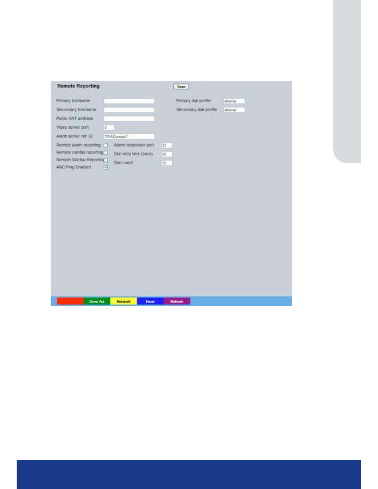
www.transvu.co.uk
Configuration & Operation Guide
97
Remote Reporting
This menu details the conguration requirements for the unit to report to a Remote Video Receiving
Centre (RVRC) following alarm activation.
Note: This menu will only be displayed if ‘Remote Reporting’ is selected in the
System Settings->Features menu.
Primary Hostname This is the IP address or URL of the initial host that the unit will transmit an
alarm message to.
Primary Dial Prole It is possible for the alarm message to be transmitted via the Ethernet network.
Secondary Hostname If the unit is unable to contact the primary host, an alternative route can be
identied via a secondary host. If there is only one alarm receiving IP address,
you must enter the details in both the primary and secondary connection
settings.
Secondary Dial Prole It is possible to select a separate dial prole for the
secondary host.
Public (NAT) Address This is the public IP (or domain name) for a unit connected to the Internet via a
NAT Router or Firewall. This eld should be left blank if NAT is not used e.g. a
private network.
Video Server Port This eld allows the RVRC to connect to the unit through a router that is using
port forwarding e.g. if the video server does not appear on port 80 (HTTP), to
the external network. Enter the port number used for forwarding here if required.
Alarm Server ref. ID This is the reference name/ID that will be presented to the RVRC viewing
application. It should therefore have some signicance to the Operator.
Remote Alarm Reporting This must be enabled for the unit to automatically connect
on alarm.
Page 98

TransVu Compact
98
Remote Cam Fail Reporting Enabling this option ensures the unit reports camera failure on any of the
inputs to the RVRC.
Remote Startup Reporting This will send an alarm report when the unit starts up. Any system resets will be
identied.
ARC Ping Enabled
Should the modem/router at the Alarm Receiving Centre be dormant, the unit will
‘Ping’ the ARC prior to sending reporting data.
Note: Some routers will not respond to ‘Ping’.
Alarm Responder Port This species the network port number used for reporting to the alarm server. In
normal circumstances this should be left at the default value (23).
Dial Retry Time (secs) If the initial connection attempt fails, the unit will wait for the specied time
period (in seconds) before attempting to re-connect.
Dial Count This is the time (in minutes) the unit will continue to attempt to connect. A
setting of ‘0’ means no limit and the unit will continue to try and connect until
successful.
Page 99
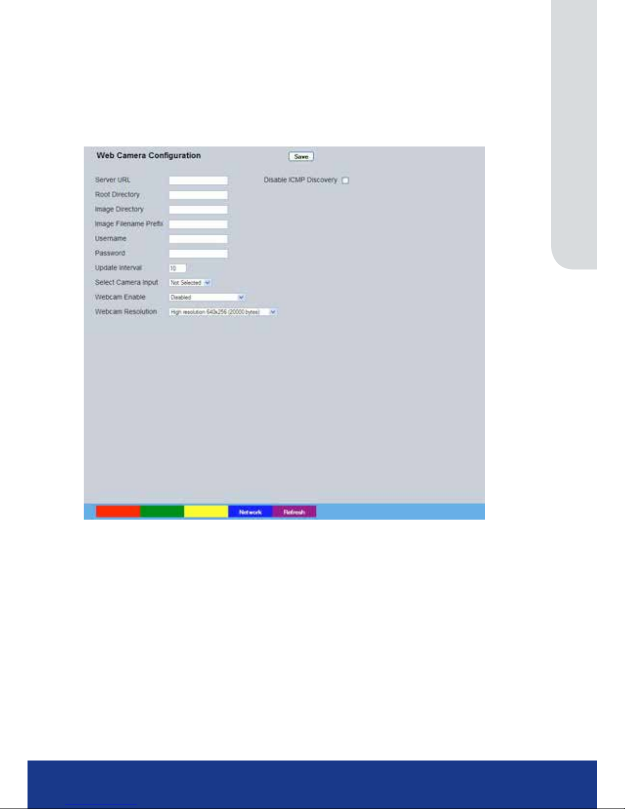
www.transvu.co.uk
Configuration & Operation Guide
99
Web Cam
Any of the video inputs on the unit can be made available for transmission to a webserver via a
designated webcam server. These images can then be incorporated into a web page and accessed
via a standard web browser.
Note: This menu will only be displayed if ‘Webcam Support’ is selected in the
System Settings->Features menu.
Server URL This is the IP address, URL or Domain Name of the WEBCAM Server. Images
will be uploaded from the unit to this server at specied time intervals.
Root Directory This is the main/root directory on the webcam server where the image directory
will be located.
Image Directory This directory will be created when the initial image is uploaded to the webcam
server, it is the directory where all images will be saved on the server.
Image Filename Prex This is an identier for images sent from the unit and will be stored as a prex
to the le name.
Username If it is necessary to use an authentication process to access the webcam server,
enter the relevant username here.
Password If it is necessary to use an authentication process to access the webcam server,
enter the relevant password here.
Update Interval
This is the minimum update interval between each image transmitted from the unit.
Select Camera Input
This allows individual video inputs to be enabled for upload to the webcam server.
Webcam Enable The Web Cam function can be: ‘Always Enabled’, ‘Enabled when system SET’,
‘Enabled when system UNSET’ or ‘Disabled’.
Webcam Resolution Select a High, Medium or Low webcam resolution settings to best match the
monitor settings of the operator receiving the images.
Page 100
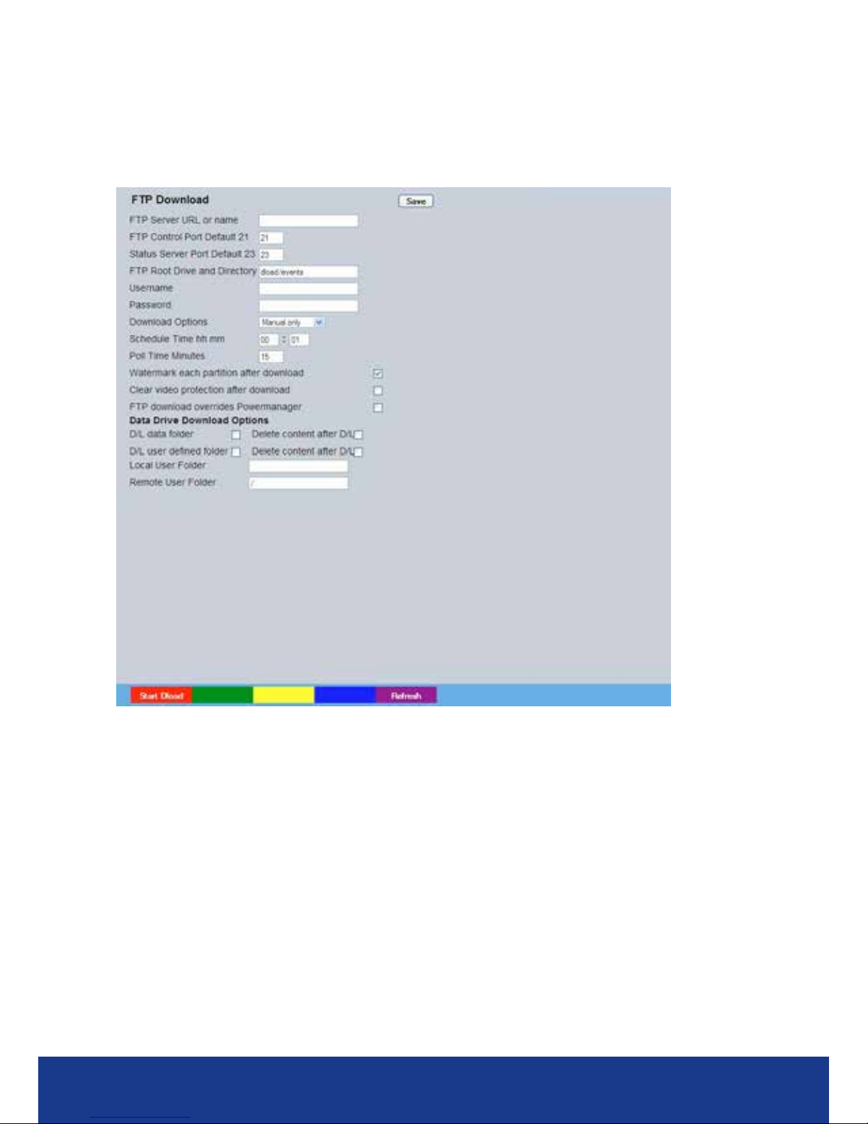
TransVu Compact
100
FTP Download
The unit can archive images to a central FTP (File Transfer Protocol) server. This could be on
receipt of an alarm, activation of the Activity Detection or at a scheduled time to backup recorded
video. Using FTP in a multi-unit application ensures that all les are stored in one central location for
each of the units, offering efcient le management and easy review capabilities.
FTP Server IP URL or name
This is the IP address, URL or name of the FTP server the unit will connect to
for FTP image download purposes.
FTP Control Port The default port for FTP use is port 21. If this port has
already been allocated on the network, it is possible to identify and allocate an
alternative port.
Status Server Port Default The default port for the Server Status function is port 23, if this port has
already been allocated on the network, it is possible to identify and allocate an
alternative port number.
FTP Root Drive and Directory
This is the directory where the images are to be stored, it is recommended that
a name associated with the unit be used for ease of retrieval.
Username If it is necessary to use an authentication process to access the FTP server,
enter the relevant username here.
Password If it is necessary to use an authentication process to access the FTP server,
enter the relevant password here.
 Loading...