

Page 1
Rev 3.5
April 2014 751TS0027
CineMonitorHD Evolution
Operator Manual
Page 2

Page 2 CineMonitorHD Evolution
ABOUT
This Operator Manual describes the use of the Transvideo CineMonitorHD Evolution family.
The first CineMonitor has been introduced to the Film Industry during year 1995.
The CineMonitorHD Evolution is our latest contribution to the Digital Cinematography world, including
advanced decision tools for the HD world.
The CineMonitorHD Evolution family includes the following products:
CineMonitorHD
6
SBL Evolution 6” HD Monitor SuperBright
CineMonitorHD
6
eSBL Evolution 6” HD Monitor enhanced SuperBright
CineMonitorHD
6
X-SBL Evolution 6” HD Monitor eXtreme SuperBright
CineMonitorHD
8
Evolution 8” HD Monitor
CineMonitorHD
8
SBL Evolution 8” HD Monitor SuperBright
CineMonitorHD
8
eSBL Evolution 8” HD Monitor enhanced SuperBright
CineMonitorHD
10
SB Evolution 10” HD Monitor SuperBright
CineMonitorHD
12
SB Evolution 12” HD Monitor SuperBright
CineMonitorHD
15
SBL Evolution 15” HD Monitor SuperBright
CineMonitorHD
15
Studio Evolution 15” HD Monitor Studio version
If the physical, electrical and optical characteristics of the products are different, the user interface is
the same.
Several configurations are optionally available for this family of products.
There is the choice at the order between several input boards, which gives different functionalities
described in this document. Some options can be not implemented in your CineMonitorHD Evolution.
This manual describes CineMonitorHD Evolution with Software 7.23e (and up).
Depending of the hardware, it is possible to upgrade the CineMonitorHD Evolution. For that, contact
us or your local Transvideo representative.
The products described in this manual are professional equipment. Utilization of these products
implies knowledge of basics in video signal management, HDTV and film making concept.
Page 3

Operator Manual Rev 3.5 Page 3
WARNING & CAUTION
WARNING:
There is very high voltage inside of the component. Risk of injury or death.
WARNING:
This product must be used in a correct grounded electrical environment; ground defects can create
severe problems to the equipment, the picture quality and even cause danger for the user.
WARNING:
Copyright law and international treaties protect this product, its design and its software. One
or several international patents apply to the CineMonitorHD Evolution.
Unauthorized reproduction or distribution of this product or its design or its software or any
portion of them, may result in severe civil and criminal penalties, and will be prosecuted to the
maximum extent possible under the law.
CAUTION:
Warranty is void is the product is opened. The unit contains electrostatic sensitive devices, which can
be damaged or destroyed if you touch them. Very high voltage is present in the product and there is
some risk of electric shock if opened by a non-accredited technician. Standard ESD procedures must
be strictly followed during disassembly/re-assembly of the unit.
The user and/or technician assume full responsibility or any risk of bodily injury, death or property
damage arising out of the use or disassembly or repair of this equipment. In no event shall Transvideo
S.A. or its local representatives be liable to a user, technician or third party for any loss of income or
any damage of any kind resulting from the use of or work on the said equipment.
Page 4

Page 4 CineMonitorHD Evolution
TABLE OF CONTENT
ABOUT ..................................................................................................................................................... 2!
WARNING & CAUTION ............................................................................................................................... 3!
TABLE OF CONTENT .................................................................................................................................. 4!
INTRODUCTION ......................................................................................................................................... 7!
Unpacking ......................................................................................................................................... 7!
General safety instructions ............................................................................................................. 7!
Power requirements ......................................................................................................................... 8!
Start-up ............................................................................................................................................. 9!
PRODUCT OVERVIEW .............................................................................................................................. 10!
Parts identification ......................................................................................................................... 10!
User interface ................................................................................................................................. 12!
Direct functions ............................................................................................................................ 12!
Rotating knob ............................................................................................................................... 13!
USING THE DIRECT FUNCTIONS ............................................................................................................... 14!
Color Temperature & Dimming ..................................................................................................... 14!
Markers ............................................................................................................................................ 15!
Measurements ................................................................................................................................ 16!
Waveform ..................................................................................................................................... 16!
Histogram ..................................................................................................................................... 17!
Vectorscope ................................................................................................................................. 17!
Zoom ................................................................................................................................................ 18!
Zoom pixel to pixel ....................................................................................................................... 18!
1.33x zoom .................................................................................................................................. 18!
Zoom in SD .................................................................................................................................. 18!
Aspect Ratio and Anamorphic desqueeze ................................................................................... 18!
Assign user key ............................................................................................................................... 19!
Input Selection ................................................................................................................................ 20!
Display adjustments ....................................................................................................................... 20!
Page 5

TABLE OF CONTENT
Operator Manual Rev 3.5 Page 5
M
ENU FUNCTIONS .................................................................................................................................. 21!
HELP ................................................................................................................................................ 21!
DISPLAY MODE .............................................................................................................................. 21!
BLUE CHECK .................................................................................................................................. 21!
COLORIMETRY ............................................................................................................................... 22!
INPUT PROFILE .............................................................................................................................. 22!
AUTO ........................................................................................................................................... 22!
LINEAR ......................................................................................................................................... 22!
REC709 ........................................................................................................................................ 22!
S-LOG .......................................................................................................................................... 22!
S-LOG2 ........................................................................................................................................ 22!
CANON-LOG ............................................................................................................................... 22!
LOG-C .......................................................................................................................................... 22!
BLACK LEVEL ................................................................................................................................. 23!
LOCK ................................................................................................................................................ 23!
TOOLS ............................................................................................................................................. 23!
BLUETOOTH ................................................................................................................................ 23!
AUDIO .......................................................................................................................................... 24!
TIMECODE ................................................................................................................................... 24!
LENS READER ............................................................................................................................. 24!
FOCUS HELPER .......................................................................................................................... 26!
FRAMELINE ................................................................................................................................. 26!
HORIZON ..................................................................................................................................... 27!
LIMITS .......................................................................................................................................... 28!
MEASUREMENTS ........................................................................................................................ 29!
TALLY .......................................................................................................................................... 30!
PICTURE FX .................................................................................................................................... 31!
SCAN ................................................................................................................................................ 31!
TECHNICAL ..................................................................................................................................... 32!
CVBS STD SELECT ..................................................................................................................... 32!
NTSC ............................................................................................................................................ 32!
ACCESSORY ............................................................................................................................... 32!
HDMI MODE: CANON/NORMAL ................................................................................................. 32!
GPI ............................................................................................................................................... 32!
VOLTAGE ALARM ........................................................................................................................ 33!
REVERSE SCROLLING ................................................................................................................ 33!
EXIT TEMPO ................................................................................................................................ 33!
LIGHTS ......................................................................................................................................... 33!
MEMORY ......................................................................................................................................... 34!
MEM 1 … MEM 4 ......................................................................................................................... 34!
PRESET ........................................................................................................................................ 34!
Page 6

TABLE OF CONTENT
Page 6 CineMonitorHD Evolution
S
ERVICE & MAINTENANCE ....................................................................................................................... 35!
General ............................................................................................................................................ 35!
Useful tips ....................................................................................................................................... 35!
Cleaning ....................................................................................................................................... 35!
Full reset ....................................................................................................................................... 35!
Hardware, Software and Firmware ............................................................................................... 36!
Updating your CineMonitorHD Evolution ..................................................................................... 36!
Color Calibration ............................................................................................................................. 37!
Product Return ............................................................................................................................... 37!
SPECIFICATIONS ..................................................................................................................................... 38!
Common Characteristics ............................................................................................................... 38!
List of Standards per Input ............................................................................................................ 39!
Specific Characteristics ................................................................................................................. 39!
TRANSVIDEO EQUIPMENT LIMITED WARRANTY ........................................................................................ 41!
Page 7

Operator Manual Rev 3.5 Page 7
INTRODUCTION
Unpacking
Packing list
Control the content of the package accordingly to the packing list.
Transportation
The CineMonitorHD is delivered in a rugged waterproof case. Use this case for storage and
transportation.
2 years warranty
All CineMonitorHD are covered by a 2 years limited warranty unless otherwise noted.
Get a 3
rd
year for free by registering your product online within the first month of the purchase.
http://www.hd4dp.com/register-my-product
General safety instructions
IMPORTANT:
Do not use damaged cables with this equipment.
Damaged connectors may seriously damage this equipment.
Never seal the monitor in a plastic bag.
Never use the monitor in full sun with a Raincover.
Before using the monitor make sure that the product is not damaged, that the protective glass is not
broken and that the connector do not have missing pins, foreign objects inside the housing.
The CineMonitorHD needs to be in a ventilated area for a proper cooling. Prolonged use in confined
environment without ventilation can damage the monitor.
Cables
The cables must be in good condition and adapted to the environment where you are working. A bad
quality or wrong-wired cable may damage this equipment or other equipment attached to it and/or
create interferences.
The video cable must be adapted for carrying HD SDI signals. Proper 75 Ω connectors must be used.
Always check the connector before plugging a cable to your monitor.
Transvideo offers high quality cables for cameras, power supplies and other equipment. Contact
Transvideo S.A. or its local representative in case of need.
Installation
The CineMonitorHD must be securely mounted on the camera or on its location of use. Several
mounting points with ¼-20” nut are present on this equipment for a secured professional use.
Page 8

INTRODUCTION
Page 8 CineMonitorHD Evolution
Do not use the monitor with loose fixation or damaged brackets for your own safety and that of
others working with you.
Transvideo manufactures high quality brackets and accessories for the comfort of use and security
for the equipment and user. Please contact Transvideo S.A. or its local representative in case of need
or visit http://www.hd4dp.com.
Power requirements
Only DC Voltage powers this product.
AC voltage can be used with an appropriate AC/DC converter
Recommended AC power adaptors:
CineMonitorHD
6
SBL Evolution Transvideo AL30
CineMonitorHD
6
eSBL Evolution Transvideo AL30
CineMonitorHD
6
X-SBL Evolution Transvideo AL30
CineMonitorHD
8
Evolution Transvideo AL30
CineMonitorHD
8
SBL Evolution Transvideo AL30
CineMonitorHD
8
eSBL Evolution Transvideo AL30
CineMonitorHD
10
SB Evolution Transvideo AL63
CineMonitorHD
12
SB Evolution Transvideo AL63
CineMonitorHD
15
SBL Evolution Transvideo AL63
CineMonitorHD
15
Studio Evolution Transvideo AL63
The input power voltage range is extremely wide from 10 to 36 V DC (except specified differently).
Power instructions
The power consumption slightly varies with the input voltage, the operating temperature and the
equipment configuration. The internal power supply is protected against reverse polarity. Over
voltage may cause severe damages to the equipment and/or to other equipment connected to it.
This product must be used in a properly grounded electrical environment. Ground defects can create
severe problems to the equipment and/or picture quality and may even cause danger for the user.
Turning power On/Off
The ON/OFF Switch is on the back side of the monitor.
The product needs a certain time to reach its nominal brightness.
This time can vary with the temperature.
In OFF position, the power consumption is null.
Galvanic insulation
For safety of use the CineMonitorHD family feature a galvanic insulation of the DC input. Do not
connect the power ground to the chassis of the monitor or to the metallic body of the power
connector in order to keep the galvanic insulation. The galvanic insulation is rated at 1000VDC. The
chassis of the monitor is connected to the video ground.
Page 9

INTRODUCTION
Operator Manual Rev 3.5 Page 9
Anton-Bauer batteries / FuelReader™
TransvideoLabs engineer’s integrated communication between the fuel computer of Logic Series
Digital batteries from Anton-Bauer and CineMonitorHD Evolution. The FuelReader™ gives to the user
a view of the remaining available percentage of the battery and the time to run.
On 6” and 8” CineMonitorHD Evolution, you need to use the battery socket from to enjoy the benefits
of the FuelReader™. On 10”, 12”, and 15” CineMonitorHD Evolution you need to order the monitor
with the Anton-Bauer Gold Mount socket.
WARNING RISK OF FIRE:
It is always recommended to remove the power source from the monitor when you do not use it
and/or when you travel. Especially if you place the monitor in a closed environment (bag, box, …).
Start-up
① Connect an appropriate power supply to the XLR4 connector or a battery if any socket is
available.
② Connect a video source (SDI, HDMI, CVBS) to the corresponding input
③ Set the power switch to ON
④ Select the correct input with "Inputs" key
Page 10
Page 10 CineMonitorHD Evolution
PRODUCT OVERVIEW
Parts identification
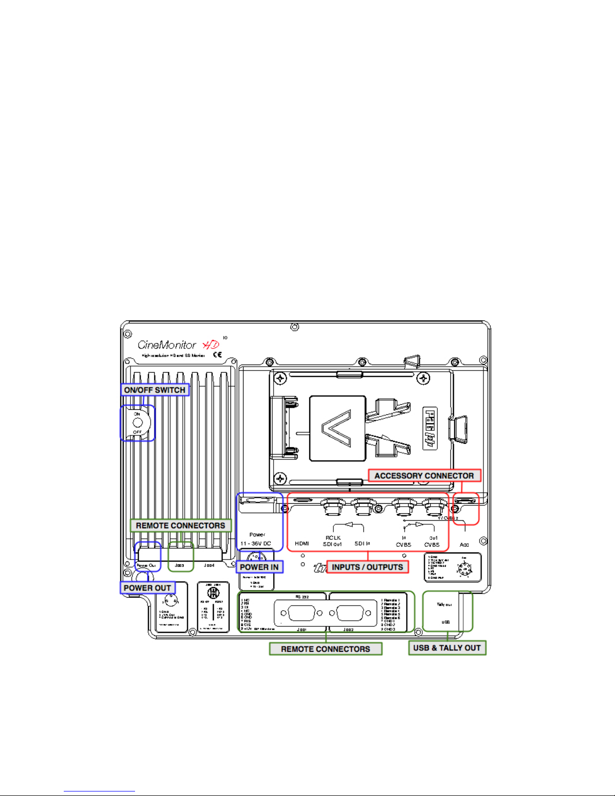
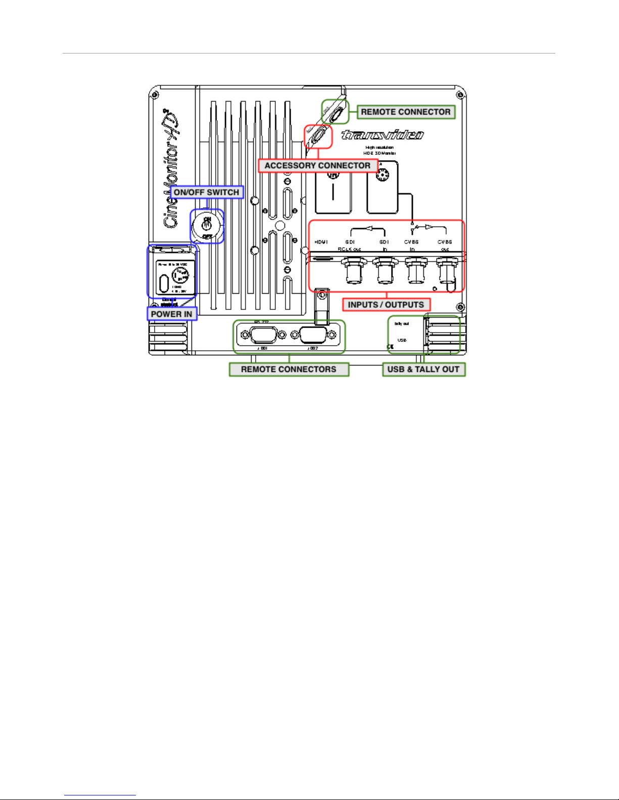
All connectors are on the back of the monitor. Depending on the size of the monitor, the connectors
and their location may differ.
The CineMonitorHD Evolution family offers a video connector panel common to all sizes. 10" to 15"
monitors also provide a power out connector and a battery plate (more details in chapter
"S
PECIFICATIONS").
Figure 1 to 2 show the backs of a 10" and a 8” CineMonitorHD Evolution.
Figure 1: CineMonitorHD10 Evolution back
Page 11
PRODUCT OVERVIEW
Operator Manual Rev 3.5 Page 11
Figure 2: CineMonitorHD8 Evolution back
Page 12

PRODUCT OVERVIEW
Page 12 CineMonitorHD Evolution
User interface
The CineMonitorHD Evolution family offers a user interface common to all sizes. Some functions are
directly accessible from the "direct functions" keypad, others from the menu with use of the rotating
knob.
The CineMonitorHD screen is partitioned in two areas:
① The picture zone displays the picture from the camera in 16/9 format
② The tools zone displays tools and measurements in the remaining area of the screen.
Figure 3 show the front of a 8” CineMonitorHD Evolution.
Figure 3: CineMonitorHD8 Evolution front
Direct functions
Several direct functions are available from the keypad.
One short press on a key gives access to the function.
One long press (more than 2 seconds) on a key gives access to the sub functions of the related
function (if any). Pressing F1…F4 enables to adjust those sub functions.
Depending of the function, options and environment, the content of F1…F4 may differ. Pressing a key
will activate or deactivate the sub function. An activated sub function is highlighted by an orange text
while an inactivated function prompts in white.
In some specific case, F4 may extend the selection to a second page of sub menu.
Page 13

PRODUCT OVERVIEW
Operator Manual Rev 3.5 Page 13
Rotating knob
The menu knob is a rotating encoder with a push function. It is used to access and navigate in the
menus, adjust some parameter values, validate and exit functions by turning or pushing it.
One sort press on the knob gives access to the menu. Rotating the knob enables to navigate
between the menu items. Pushing the knob gives access to the sub menu of the highlighted menu
item.
Selecting EXIT exits from the current menu level to the previous (if any). A long push on the knob exits
from the menu. Exiting the menu is also possible by automatic temporization, adjustable in MENU /
TECHNICAL.
Page 14

Page 14 CineMonitorHD Evolution
USING THE DIRECT FUNCTIONS
Color Temperature & Dimming
Short push on Col. Temp. Dimming – toggles calibration modes:
FULL BRIGHT: maximum brightness and power consumption, the color calibration is deactivated
STANDARD CALIBRATED: standard mode, the brightness (200Nits) and white point are calibrated
according to the settings of MENU / COLORIMETRY
USER SET: turning the rotating knob adjusts the brightness from 10 to 100% while color calibration
is preserved. Allows having a reduced power mode between two takes.
Long push on Col. Temp. Dimming – accesses the settings of the Standard Calibrated mode
Press F1 to choose D56 calibration
Press F2 to choose D65 calibration
Press F3 to choose manual calibration (Adjustable in MENU / COLORIMETRY)
It is necessary to wait a few seconds after pressing the key before loading of the correct lookup table.
Page 15

USING THE DIRECT FUNCTIONS
Operator Manual Rev 3.5 Page 15
Markers
Short push on Marker – activates or deactivates the selected marker(s).
Long push on Marker to select the markers to display.
Not active when ZOOM or anamorphic modes are selected.
Long push on Marker – marker(s) selection
First page
Press F1 to activate / deactivate 4:3 marker
Press F2 to activate / deactivate 14/9 marker
Press F3 to activate / deactivate 16/9 marker
Press F4 to access next page
Second page
Press F1 to activate / deactivate safe area
Press F4 to access previous page
This menu is contextual; some functions can be unavailable depending of the video standard.
When SAFE AREA is selected in the sub menu, one short press on the Marker key displays "TURN
TO ADJUST SAFE AREA: XX%". Rotating the knob makes it possible to adjust the safe area on the
picture from 10 to 99%. SAFE AREA is selected by default at start-up or after a reset and with a value
of 90%.
Page 16
USING THE DIRECT FUNCTIONS
Page 16 CineMonitorHD Evolution
Measurements
Short push on Measure – toggles the different views of the selected measurement
Long push on Measure to select the measurement to display.
The brightness of the reticule and of the spot as well as the background transparency in overlay
mode (for waveform and vectoscope) can be adjusted in MENU / TOOLS / MEASUREMENT.
White and black clipping alert can be configured in MENU / TOOLS / LIMITS. The same limits are
used for the waveform and the histogram. Setting these limits is useful to have a visual alert on the
measurement tools if there is a risk of overexposure or of loss of black details.
Waveform
Long push on Measure – measurement selection
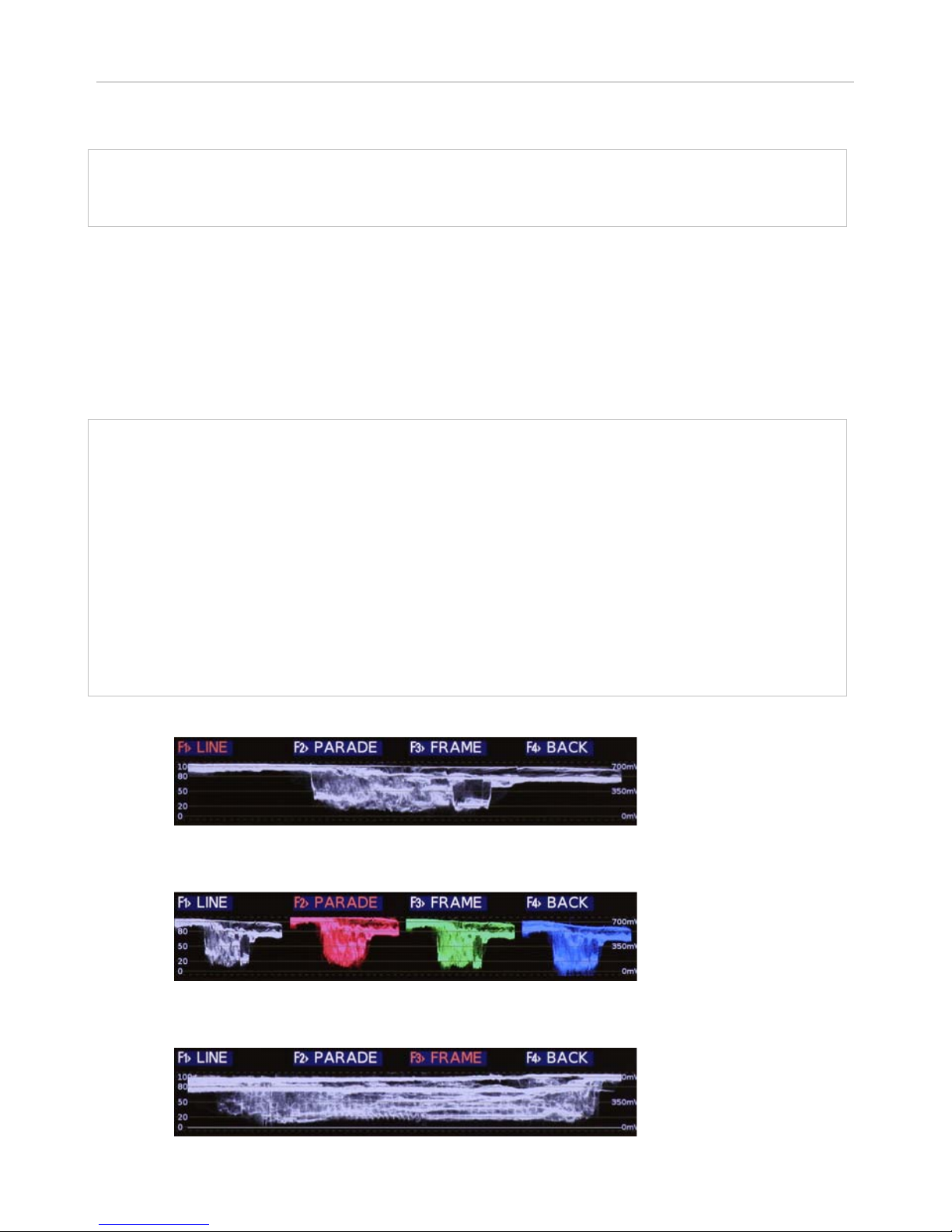
Selecting "F1: WAVE" gives access to the selection of the waveform modes.
Press F1 to display the waveform in line mode
Press F2 to display the waveform in parade mode
Press F3 to display the waveform in frame mode
Press rotating knob to exit from menu.
Then a short push on Measure toggles the different views of the selected waveform mode (if any).
It also gives the possibility to adjust the size of the waveform by using the rotating knob (3 sizes
available)
LINE Displays one single spot (Y, Red, Green or Blue)
PARADE Displays Y, R, G, B, Cr & Cb in parade mode.
Available modes: YRGB / YGBR / RGB / GBR / YCrCb
FRAME Displays Y, R, G, B in frame mode (or sweep mode).
The content of one frame/picture is displayed.
Page 17
USING THE DIRECT FUNCTIONS
Operator Manual Rev 3.5 Page 17
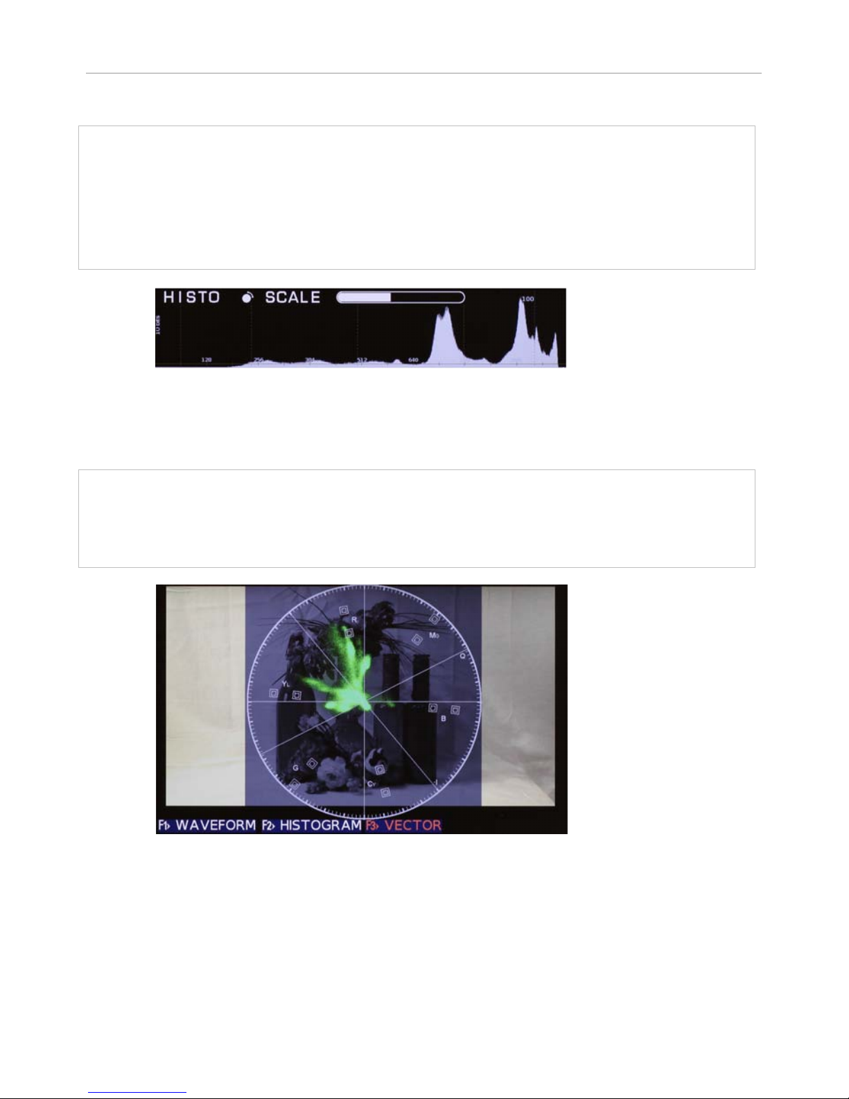
Histogram
Long push on Measure – measurement selection
Selecting "F2: HISTO" displays the histogram.
Press rotating knob to exit from menu.
Then a short push on Measure gives the possibility to adjust the scale of the histogram by using the
rotating knob
Vectorscope
Long push on Measure – measurement selection
Selecting "F3: VECTOR" displays the vectorscope.
Press rotating knob to exit from menu.
Page 18

USING THE DIRECT FUNCTIONS
Page 18 CineMonitorHD Evolution
Zoom
Short push on Zoom – toggles between different zoom modes.
OFF / 1.33x zoom / Pix to pix zoom
When activating the zoom, a pictogram showing the relative position of the magnified zone is
displayed.
Arrows move the picture on Top/Bottom, Left/Right positions. Moving increments are proportional
to 1/8 of the video standard. Fine adjustment can be made by rotating the rotating knob.
A long push on the Zoom key centers the picture, the next push sends back to the full picture
display.
Zoom pixel to pixel
Displays the picture in full resolution mode (pixel to pixel or 1:1).
Beyond the native resolution of the picture, magnify implies to create pixels that doesn’t exist. This is
why the pixel to pixel mode (1:1 zoom) is the higher magnification ratio in a Transvideo monitor.
1.33x zoom
The 1.33x zoom mode magnifies the active 16/9 area of the picture output by the Arri Alexa in 4:3
mode.
Zoom in SD
In SD, the picture is displayed in full screen. In this case there is an important magnification ratio
applied to the original picture. The resultant picture includes created pixels and lines and cannot be
considered as a proof. In this mode the waveform will be superimposed to the picture.
Aspect Ratio and Anamorphic desqueeze
Short push on Aspect ratio – toggles aspect ratio:
1.33:1 (4/3) SD only
1.78:1 (16/9) HD & SD
Anamorphic 1.3x HD only (anamorphic desqueeze for 1.3x lenses on a 16/9 sensor)
Anamorphic 2x HD only (anamorphic desqueeze for 2x lenses on a 4:3 sensor)
2.40:1 SD only
3.20:1 HD & SD (anamorphic desqueeze for 2x lens on a 16/9 sensor)
No sub functions in Aspect Ratio
Page 19

USING THE DIRECT FUNCTIONS
Operator Manual Rev 3.5 Page 19
Assign user key
Short push on User – activates or deactivates selected user function.
Long push on User to select the user function.
Long push on User – user function selection
First page
Press F1 to select STATUS as the user function
Displays the status of the monitor and the input voltage from the power supply or the battery.
Press F2 to select FOCUS helper as the user function
Activates the Focus Helper function as programmed in MENU / TOOLS / FOCUS HELPER.
Press F3 to select EXPOsure control as the user function
Gives access to the Exposure Control as configured in MENU / TOOLS / LIMITS.
FOCUS and EXPO may be selected simultaneously. If both are activated, pressing User key set up:
a. FOCUS + EXPO / b. FOCUS / c. EXPO / d. nothing
Press F4 to access next page
Second page
Press F1 to select High/Low (high- or low- light details) as the user function
In high mode, the 50%-100% grey scale is shifted to 0-50% to enhance the high-light details.
In low mode, the 0-50% grey scale is shifted to 50%-100% to enhance the low-light details.
Press F2 to select HORIZON as the user function.
Activates or deactivates the horizon as programmed in MENU / TOOLS / HORIZON.
Press F3 to select ZONE as the user function
Adjusts the acquisition zone for the waveform and vectorscope.
Active when "1 LINE" or "12 LINE" are selected in MENU / TOOLS / MEASUREMENT.
Press F4 to access previous page
Page 20
USING THE DIRECT FUNCTIONS
Page 20 CineMonitorHD Evolution
Input Selection
Short push on Input Sel – toggles video inputs.
Long push on Input Sel to select the active video inputs.
Long push on Input Sel – selection of the active video inputs
An active input is highlighted in orange, an inactive in white. An inactivated input cannot be
selected by the Input Sel key.
Press F1 to activate or deactivate SDI
Press F2 to activate or deactivate CVBS
Press F3 to activate or deactivate the ACCessory input (YPrPb or RGB or CVBS)
Press F4 to activate or deactivate HDMI
Inactivating the accessory input reduces the power consumption of the CineMonitorHD of about 4
Watts.
The format of the ACC input can be configured in MENU / TECHNICAL when ACC input is selected. It
is possible to select between component YPrPb, component RGB or CVBS.
Display adjustments
Short push on ADJ – toggles parameters to adjust:
Brightness, Contrast, Saturation, Hue (NTCS only)
Adjust the value by rotating the knob.
Validate by pushing the knob.
IMPORTANT:
The settings are different for each input. All settings are stored in setup memories. There is one
memory per input. That means you can setup the ACC input differently of the SDI input. It is
useful with some specific cameras offering a viewfinder menu and a HD SDI output.
Page 21

Operator Manual Rev 3.5 Page 21
MENU FUNCTIONS
HELP
Gives access to maintenance menu.
MONITOR INFO
Gives software (SW) and firmware (FW) versions of all electronic boards of the monitor.
UPDATE
Allows the SW and FW updates of all electronic boards of the monitor.
To update a CineMonitorHD Evolution, refer to chapter "S
ERVICE & MAINTENANCE", section "Updating
your CineMonitorHD Evolution".
ADVANCED UPDATE
Gives access to advanced functions for monitor updates. For experts only.
DISPLAY MODE
Gives access to 3 display modes: COLOR, GREEN and B/W
COLOR
Standard mode, displays the picture with 16 million colors, 256 gray levels.
GREEN
Display the picture in green color only.
TINT and SATURATION are not working in this mode.
This mode has been invented by Transvideo in 1990 and is used since this time in Film & Night Vision
systems.
B/W
Displays the picture with 256 gray levels.
TINT and SATURATION are not working in this mode.
BLUE CHECK
Sets the monitor in BLUE ONLY mode.
This mode is used to calibrate the monitor with an incident color bar.
Page 22

MENU FUNCTIONS
Page 22 CineMonitorHD Evolution
COLORIMETRY
MANUAL
Allows the manual adjustment of RGB gain (from 0 to 2, nominal 1.00) and offset of the black (127mV to + 126mV, nominal 0 mV).
The nominal value in manual mode corresponds to the D65 setup.
IMPORTANT:
In MANUAL there is a risk of displaying wrong colors; this option must be used carefully.
D56 CALIBRATED
Sets the monitor for a white point DAYLIGHT 5600
CIE 1931 Coordinates: x: 0.3310
y: 0.3460
D65 CALIBRATED
Sets the monitor for a white point DAYLIGHT 6500
CIE 1931 Coordinates: x: 0.3127
y: 0.3290
INPUT PROFILE
AUTO
Adjusts the response of the monitor according to the SDI metadata information (if any).
This menu disappears if no metadata are found.
LINEAR
Adjusts the response of the monitor with a linear gamma correction.
REC709
Adjusts the response of the monitor to a video signal using REC709 encoding.
S-LOG
Adjusts the response of the monitor to a video signal using S-Log encoding.
S-LOG2
Adjusts the response of the monitor to a video signal using S-Log2 encoding.
CANON-LOG
Adjusts the response of the monitor to a video signal using Canon-Log encoding.
LOG-C
Adjusts the response of the monitor to a video signal using Log C encoding. It is possible to adjust
the EI (Exposure Index) to 100, 125, 160, 200, 250, 320, 400, 500, 640, 800.
Page 23

MENU FUNCTIONS
Operator Manual Rev 3.5 Page 23
BLACK LEVEL
IP/BL DISPLAY: ON/OFF
Activates or deactivates the display of Input Profile and Black Level information.
STANDARD
Sets the black level of the video signal to 64 / 0 IRE
EXTENDED
Sets the black level of the video signal to 4 / -7 IRE
ADJUST
Intermediary and adjustable black level, from 4 to 64 (-7 to 0 IRE).
LOCK
The lock function prevents errors after configuration and calibration of the monitor.
When the function is activated, “LOCK” is displayed on the screen at each attempt to enter in the
menu or to access a direct function.
Pressing the rotating knob for more than 5 seconds gives the user access to the menu where she/he
will be able to deselect LOCK.
IMPORTANT:
Input Sel key is never locked.
TOOLS
BLUETOOTH
Bluetooth activation and device selection. Available only if the monitor is equipped with a Bluetooth
module. Contact us for more information.
BLUETOOTH: ON/OFF
Activates or deactivates the function.
UPDATE DEVICE
Detects all Bluetooth devices near the monitor location.
SELECT DEVICE NO. #
Connects the monitor to the Bluetooth device number “#” given by menu “UPDATE DEVICE”.
ABOUT WIRELESS HORIZON (VirtualHorizon3):
If a VirtualHorizon3 has already been connected to the monitor, the monitor will automatically
connect to this VirtualHorizon3.
Page 24

MENU FUNCTIONS
Page 24 CineMonitorHD Evolution
AUDIO
Displays the SDI embedded audio presence and a bargraph showing one audio pair on the 8 possible
pairs.
AUDIO: ON/OFF
Activates or deactivates the function.
CHANNEL PAIR: X
Selection of the pair displayed on the bargraph with the rotating knob.
POSITION
Allows the user to place the tool in different position of the screen.
When USER is selected, use arrows and the rotating knob to move the tools.
DEFAULT replaces the tool at the factory preset.
TIMECODE
Displays the embedded VITC 1 or 2 or LTC Timecode.
TIMECODE: ON/OFF
Activates or deactivates the function
ATC: AUTO, LTC, VITC1, VITC2
Selection of the displayed ATC. When AUTO is selected the first time code present is displayed (1:
LTC, 2: VITC1, 3: VITC2)
POSITION
Allows the user to place the tool in different position of the screen.
When USER is selected, use arrows and the rotating knob to move the tools.
DEFAULT replaces the tool at the factory preset.
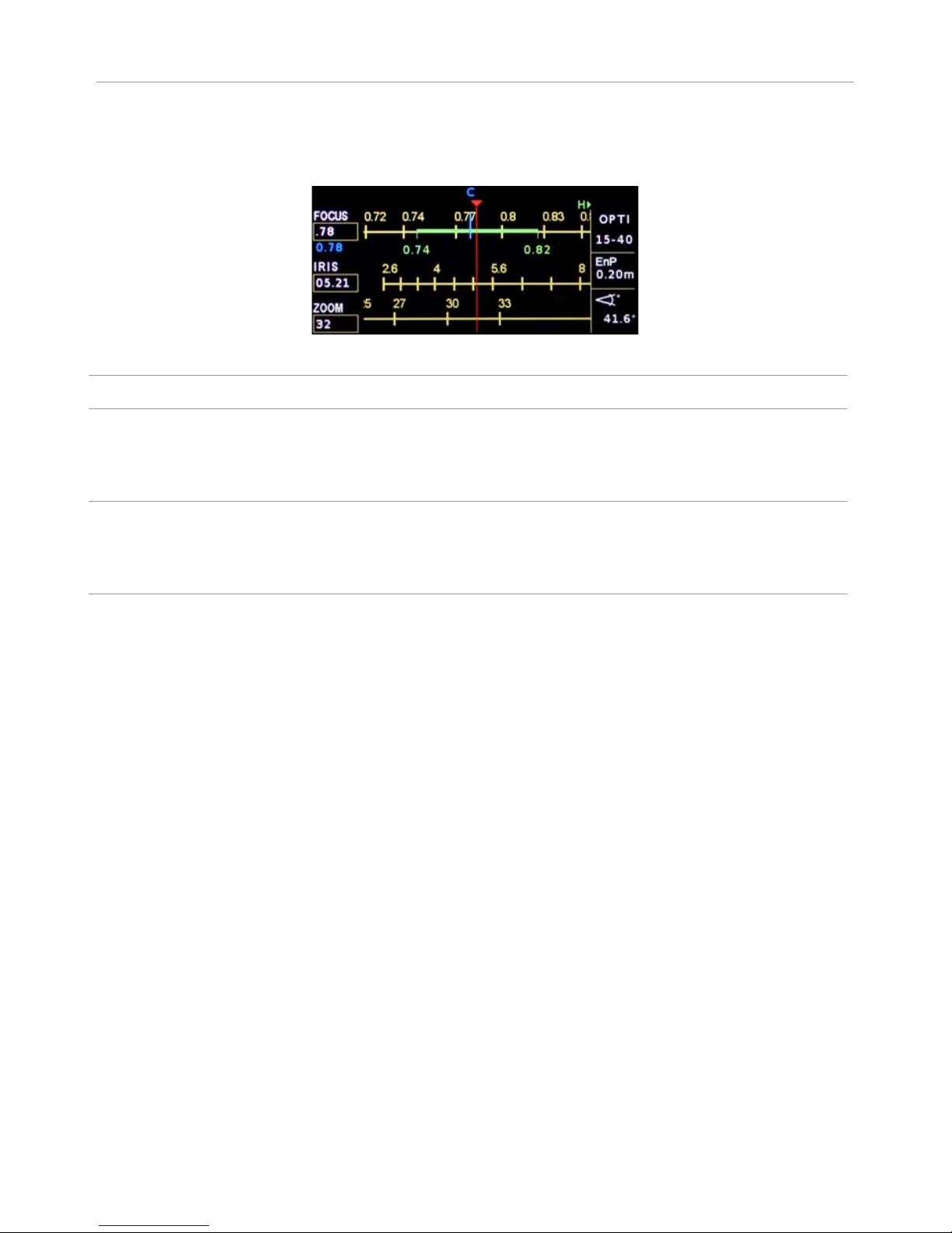
LENS READER
The LensReader from Transvideo reads the metadata from /i and LDS lenses to display in real time
the iris, focus and zoom on an intuitive graphic representation. The LensReader also displays the
depth of filed and the hyperfocal point.
Two graphics are available: Mobile where the scales are moving as on a real lens; static where the
markers are moving on the scales.
Page 25
MENU FUNCTIONS
Operator Manual Rev 3.5 Page 25
When a Cine Tape Measure from Cinematography Electronics is connected via RS232 (HR25) to the
monitor, a blue marker “C” showing the measuring distance appears on the focus ring. The distance
to the object is also given as numerical value.
Supported lenses
Angénieux Optimo DP 25-250
connected to the monitor through RS232
Arri/Zeiss Ultra Prime LDS
Arri/Zeiss Master Prime
Arri/Zeiss Master Anamorphic
Arri/Fujinon Alura lightweight zoom
through the SDI outputs of Arri Alexa SUP 7 (and up)
Cooke 5/i
Cooke S4/i
Cooke mini S4/i
Cooke Anamorphic /i
through the SDI outputs of Arri Alexa SUP 8.1 (and up), or Sony
PMW- F3/F5/F55/F65 (hardware & firmware dependent)
5/I & S4/I can also be connected to the monitor through RS232
Fujinon Cabrio series
through the SDI outputs of Arri Alexa SUP 8.1 (and up), or
Sony PMW- F3/F5/F55/F65 (hardware & firmware dependent)
MODULE: ON/OFF
Activates or deactivates the function
RING: MOBILE/STATIC
Toggles between mobile and static rings display.
IRIS: DECIMAL/FRACTIONS
Toggles the iris value between decimal and fraction values.
ZONE: OP+ASSIT / ASSIST / OFF
Available only if a Cooke 5/i is connected to the monitor. The COOKE 5/i is able to light the focus and
iris scales on the operator and/or the assistant side.
Selection of the lighted zones OPERATOR + ASSISTANT or ASSISTANT ONLY
BRIGHTNESS
Adjusts the brightness of the LEDs on a COOKE 5/i lens.
UNIT
Selection of METRIC or IMPERIAL unit.
FILM
Selection of 16mm or 35mm.
Page 26

MENU FUNCTIONS
Page 26 CineMonitorHD Evolution
FOCUS HELPER
Activates a precise focus helper displaying in-focus zones with colored dots. The focus helper is
based on a complex multidimensional digital filter.
The focus helper can be remoted by the User key. The settings must have been previously configured
(Press long time User key, then set the function with F1…F4).
COLOR
Selection of the in-focus zone color.
Red, Green, Blue, Yellow, Magenta, Cyan, Black or White.
LEVEL
Adjustment of the selectivity of the filter.
OFF, 1 to 9 (9 gives the highest effect)
FRAMELINE
Enables to displays one locating cross and up to 3 programmable frames with or without center
marker and a matting generator.
CROSS
CROSS ON/OFF Activation of the cross
COLOR Selection of the color of the lines
WIDTH Selection of the width of the lines
V POS Vertical position of the cross
H POS Horizontal position of the cross
FRAME 1…3
FRAME 1…3 ON/OFF Activation of the frame
CENTER ON/OFF Activation of the center cross
COLOR Modification of the color of the frame
DOT Modification of the structure of the frame
SEND TO CENTER Sends the frame to the center of the screen.
V SIZE Size of the frame (bottom part is moving)
H SIZE Size of the frame (right part is moving)
V POS Vertical position of the frame
H POS Horizontal position of the frame
V ZOOM Vertical homothetic modification of the frame
H ZOOM Horizontal homothetic modification of the frame
SEND ALL TO CENTER
Sends all frames to the center of the screen.
BCKGND COLOR (Matting Generator)
Selects the background color outside of the frames.
Page 27

MENU FUNCTIONS
Operator Manual Rev 3.5 Page 27
HORIZON
Displays a color coded electronic leveler on screen.
SENSOR
Toggles between internal and external sensors
HORIZON Internal sensor
HORIZON 2
(1)
Internal sensor with compensation of acceleration and shocks (gyro)
WIRELESS HORIZON
(2)
Uses the wireless Transvideo VirtualHorizon3™
BETZ
(3)
Uses external electronic bubble designed by BETZ Tools
DISPLAY: NORMAL / REVERSE
(4)
Toggles the action of the horizon, normal or reversed.
RANGE
(4)
Sets the range of the horizon
HORIZON +/-5°, +/-10°, +/-22°, +/-45°, +/-90°
HORIZON 2 +/-2°, +/-5°, +/-10°, +/-22°, +/-45°, +/-90°
WIRELESS HORIZON +/-2°, +/-5°, +/-10°, +/-22°, +/-45°, +/-90°
STYLE
Displays the Horizon on the monitor and selects the style of the virtual horizon (6 different models).
0 CAL
(4)
Sets the horizon to 0. A temporization of 5 seconds allows the user to stabilize the position of the
system. Pushing the rotating knob during calibration exits from the timing.
0 CAL ON TAP: ON/OFF
(4)
Activates or deactivates the Cal-on-Tap functionality.
When activated, tap on screen or on Transvideo logo to zero calibrate the horizon.
0 CAL ON TAP THRESHOLD
(4)
Adjust the threshold level of the Cal-on-Tap.
Level 4 requests a tough tap to trigger the 0 CAL, while level 1 requests a soft tap.
POSITION
Allows the user to place the tool in different position of the screen.
When USER is selected, use arrows and the rotating knob to move the tools.
DEFAULT replaces the tool at the factory preset.
(1) Available only if VirtualHorizon2™ option is implemented in the monitor. VirtualHorizon2 is an
optional feature. It can be ordered with the monitor or implemented through an upgrade. Contact
us for more information.
(2) Available only if external bubble VirtualHorizon3™ is connected to the monitor via Bluetooth. The
monitor needs to be equipped with a Bluetooth module (option). Contact us for more information.
(3) The BETZ sensor is an external electronic bubble designed by Betz-Tools. It needs to be
connected to the monitor through J001 connector with a specific cable. Transvideo does not
support this third party equipment.
(4) Not applicable with BETZ sensor.
Page 28

MENU FUNCTIONS
Page 28 CineMonitorHD Evolution
LIMITS
Safety levels can be displayed as false colors in the picture. These levels and clippings are set in this
menu.
Safety levels can also be displayed in the measurement tools, activated in MENU / TOOLS /
MEASUREMENTS.
MAX LEVEL
Sets the maximum level (White). Adjustment goes from 100 IRE to 109 IRE
All information over the limit will be displayed in red on measurement tools and/or on the picture.
WHITE CLIPPING
Sets the top clipping level (White). Adjustment goes from 70 IRE to 109 IRE
The upper value is limited by the MAX LEVEL setting.
All information over the limit will be displayed in orange on measurement tools and/or on the picture.
BLACK CLIPPING
Sets the low clipping level (Black). Adjustment goes from -6.9 IRE to 36 IRE
The lower value is limited by the MIN LEVEL setting.
All information below the limit will be displayed in blue on measurement tools and/or on the picture.
MIN LEVEL
Sets up the minimum level (Black). Adjustment goes from -6.9 IRE to 36 IRE
All information below the limit will be displayed in violet on measurement tools and/or on the picture.
SORIN’s MARKER
Adjusts the central value of the marker in IRE.
SORIN’s MARKER WIDTH
Adjusts symmetrically the thickness of the marker within the limits of the white and black clipping
values.
All information within the Sorin's marker limits will be displayed in green on measurement tools
and/or on the picture.
OVEREXPOSURE: ON/OFF
Activates or deactivates the overexposure control on the picture.
The MAX LEVEL and the WHITE CLIPPING are displayed in false colors when activated.
SORIN’S MARKER: ON/OFF
Activates or deactivates the Sorin’s Marker on the picture.
The Sorin’s area is displayed in false colors when activated.
BLACK LIMITS: ON/OFF
Activates or deactivates the black limits control on the picture.
The MIN LEVEL and the BLACK CLIPPING are displayed in false colors when activated.
About the Sorin’s marker:
Sorin Dragoi RSC is a famous Romanian Director of Photography. He suggested this tool, which
he is using mainly to check the exposure on skin tone. The Sorin’s marker is used to see all light
equivalent zones, i.e. to see the 0 stop zone of the picture.
Page 29

MENU FUNCTIONS
Operator Manual Rev 3.5 Page 29
MEASUREMENTS
Allows different settings for the video measurement tools.
The settings apply to all video measurement tools except the histogram, which represents always the
full picture.
SIGNAL UNIT
Selects the signal measurement unit.
IRE (default unit) or BINARY
SIGNAL ANALYSIS
Selects 8 bits if the SIGNAL is 8 bits.
Default value: 10 bits
OVEREXPOSURE: ON/OFF
Activates or deactivates the overexposure zoning on the measurement tools.
SORIN: ON/OFF
Activates or deactivates the Sorin’s Marker zoning on the measurement tools.
BLACK LIMITS: ON/OFF
Activates or deactivates the black limits zoning on the measurement tools.
1 LINE
Displays the measurement of one line selected with the rotating knob.
12 LINES
Displays the measurement of a group of 12 lines.
The first line is selected with the rotating knob.
ALL LINES
Displays the measurement of the whole picture.
BACKGROUNG INTENSITY
Adjusts the overlay transparency behind the measurement tools (when displayed in front of the
picture).
SPOT INTENSITY
Adjusts the brightness of the waveform spot.
RETICULE INTENSITY
Adjusts the brightness of the waveform reticule.
About 1 - 12 Lines selection:
The selection of the acquisition zone can be allocated to the "User" key (see chapter "DIRECT
FUNCTIONS" section "User").
Page 30

MENU FUNCTIONS
Page 30 CineMonitorHD Evolution
TALLY
Tally can be activated via the GPI Sub-D9 or ACC Lemo8 connectors or via the camera REC/STOP
trigger embedded in the SDI (if any).
Several Tally signals can be used at the same time.
When Tally is connected to the ACC Lemo8 connector, the Tally trigger condition is adjustable in
MENU / TECHNICAL / GPI > ACC.
When Tally is connected to the GPI Sub-D9 connector,
- the Tally color (red/green) is adjustable in MENU / TECHNICAL / GPI > FUNCTION #;
- the Tally trigger condition is adjustable in MENU / TECHNICAL / GPI > CONDITION #.
TALLY ACC
Assigns a specific Tally mode for the ACC Lemo8 connector.
Possible configurations: OFF – ON AIR MODE – CUSTOM MODE
TALLY GPI
Assigns a specific Tally mode for the GPI Sub-D9 connector.
Possible configurations: OFF – CUSTOM MODE
TALLY SDI
Assigns a specific Tally mode for the SDI embedded Tally signal.
Possible configurations: OFF – REC MODE – ON AIR MODE – CUSTOM MODE
CUSTOM MODE
Custom Tally mode selection.
Includes RED DOT, SQUARE, DUAL SQUARE and FRAME* styles.
REC MODE POSITION
Allows the user to place the tool in different position of the screen.
When USER is selected, use arrows and the rotating knob to move the tools.
DEFAULT replaces the tool at the factory preset.
LED ON/OFF
Activates or deactivates the TALLY LED on the front panel.
* FRAME is active on “FRAME3” of the frameline.
Page 31
MENU FUNCTIONS
Operator Manual Rev 3.5 Page 31
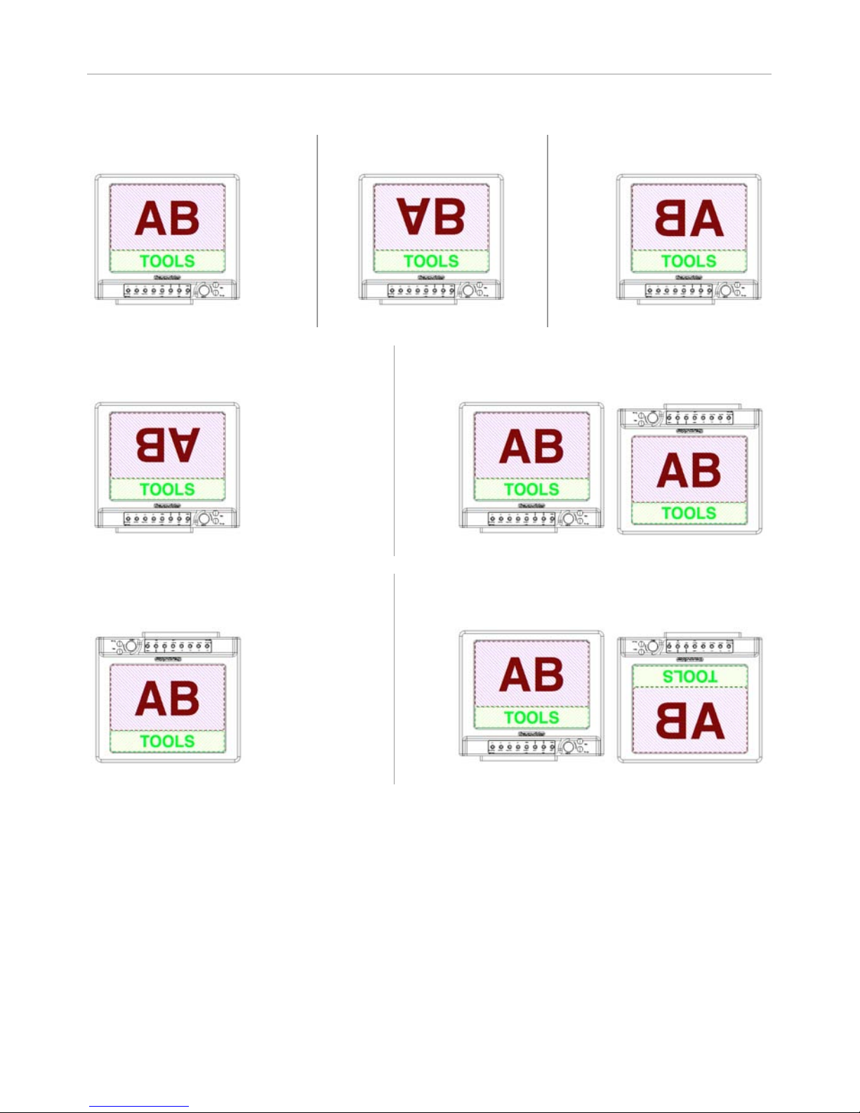
PICTURE FX
SCAN
FULL SCAN as default and only value.
NORMAL
Restores the standard display
VERTICAL FLIP
Returns the picture vertically
HORIZONTAL FLIP
Returns the picture horizontally
PICTURE REVERSE
Returns the picture horizontally and
vertically (180° rotation of the picture)
AUTO REVERSE
Makes a MONITOR REVERSE automatically if the
monitor is up side down
MONITOR REVERSE
Returns the picture, tools and menus
horizontally and vertically
AUTO FLIP REVERSE
Returns the picture automatically (vertical axis only) if
the monitor is up side down
Page 32

MENU FUNCTIONS
Page 32 CineMonitorHD Evolution
TECHNICAL
CVBS STD SELECT
Available only when CVBS or ACC input are selected
Sets the video composite standard detection.
AUTO DETECT / PAL BGHID / NTSC 3.58
NTSC
Available only when CVBS or ACC input are selected
Sets NTSC standards:
NTSC Japan (black 0 IRE)
NTSC US (black 7.5 IRE)
ACCESSORY
Available only when CVBS or ACC input are selected
Sets the accessory input:
COMPONENT RGB (HD/SD RGB signal with composite synchronization on G)
COMPONENT YPrPb (HD/SD YPrPb signal with composite synchronization on Y)
CVBS (Composite)
HDMI MODE: CANON/NORMAL
Available when HDMI input is selected
Improves the video standard switching when shooting with a Canon DSLR.
GPI
Assigns functions and trigger conditions to the ACC Tally pin and to the 4 GPIs.
ACC
Set the trigger condition of the Tally activated through ACCessory connector: ACTIVE LOW, ACTIVE
HIGH or LIGHT SENSOR *.
FUNCTION #
Assigns a function to the pin # of the GPI connector (J002)
Available functions: NONE, TALLY RED, TALLY GREEN, ZOOM, HORIZON, SWITCH INPUT, FOCUS
HELPER, EXPOSURE
CONDITION #
Sets the trigger condition of the function #
Available conditions (depending on the function): NOT ACTIVE, FALLING EDGE, RISING EDGE, LOW
STATE, HIGH STATE, LIGHT SENSOR *
* LIGHT SENSOR is a special trigger for Tally activated though a light sensor placed in front of the
camera Tally light. LIGHT SENSOR trigger is set to 1.9v DC
Page 33

MENU FUNCTIONS
Operator Manual Rev 3.5 Page 33
VOLTAGE ALARM
VOLTAGE DISPLAY: ON/OFF
FUEL READER (Anton-Bauer): ON/OFF
Displays constantly the input voltage from the power supply or the battery.
When a Logic Series Digital battery from AntonBauer is detected, the Fuel Reader also gives to the
user the remaining percentage of the battery and the time to run (see page 8).
UNIT
Toggles between Volts, Percent and Minutes (percent and and minutes only available with the
FuelReader).
ALARM
When activated the battery pictogram is displayed in red if the voltage of the power supply goes
under the threshold setting.
ALARM THRESHOLD
Sets the threshold value.
Under this value a security alert can inform the user when it is time to swap the battery on the
monitor.
POSITION
Allows the user to place the tool in different position of the screen.
When USER is selected, use arrows and the rotating knob to move the tools.
DEFAULT replaces the tool at the factory preset.
REVERSE SCROLLING
Reverses the scrolling direction in the menus.
EXIT TEMPO
Sets of the automatic exit temporization from SLOW to FAST
LIGHTS
KEYBOARD
Activates or deactivates the keyboard light (if available on the monitor). In AUTO, the keyboard light
turns automatically on when a key is pressed.
KEY DIMMER
Dimming of the brightness of the keyboard light.
It is possible to switch off completely light.
LED DIMMER
Dimming of the brightness of the power led.
It is possible to switch off completely the led.
Page 34

MENU FUNCTIONS
Page 34 CineMonitorHD Evolution
MEMORY
MEM 1 … MEM 4
4 user memories per input are available to save user’s configurations.
SAVE
Saves the current user set-up in the memory.
All configuration except INPUT SEL is stored in the memory, including picture and tools settings.
RECALL
Recalls the settings stored in the memory.
The standard settings a factory loaded in this memory, they will be replaced at the first SAVE from the
user.
PRESET
Sets the default values in the setting registers.
PRESET does not erase the user presets.
PRESET ALL INPUTS
Presets the active input and other inputs of the monitor.
PRESET SELECTED INPUT
Presets the active input only
Page 35

Operator Manual Rev 3.5 Page 35
SERVICE & MAINTENANCE
General
Please read carefully the chapter "TRANSVIDEO EQUIPMENT LIMITED WARRANTY" about the Transvideo
S.A. warranty on the equipment described in this manual.
For repairs contact Transvideo S.A. or its local representative or use the RAN procedure in the
chapter "S
ERVICE & MAINTENANCE", section "Product Return".
Useful tips
Cleaning
The painting of the CineMonitorHD is resistant to general cleaners and solvents. Do not use abrasive
products to clean your product.
The front glass is a high quality optical part. A metallic multi-layers vacuum deposit makes the antireflection coating. Do not use abrasive or acid cleaners. The microfiber cloth delivered with the
CineMonitorHD is strongly recommended to clean the glass. Remove dust and particles of the glass
before using the cloth. No liquid is normally necessary. If there is some dirt on the screen, it is
possible to remove it with clean warm water.
The microfiber cloth collects grease particle in its structure. It is necessary to wash it when necessary
with water and soap.
The microfiber cloth is orderable as spare part (refer to your local Transvideo dealer in case of need).
Full reset
If needed, a full reset of the monitor may be performed as follows:
① Connect the monitor to a power source (monitor off).
② Press the adjust (ADJ) key
③ Switch on the monitor while keeping pressed the “adjust” key until the display shows “FULL
RESET”
The monitor is back to its factory default settings. This procedure totally erases all user setup in the
memories.
Page 36

SERVICE & MAINTENANCE
Page 36 CineMonitorHD Evolution
Hardware, Software and Firmware
Basic monitor information is indicated during the startup on the display:
SOFT main board software version (microcontroller #1)
FIRMWARE main board firmware version
HARDAWARE main board hardware version
LOGO graphical user interface version
LOAD MATRIX colorimetry version
This information is useful to write down if trouble-shooting becomes necessary.
The complete list of software and firmware versions of all electronic boards may be found in MENU /
HELP / MONITOR INFO.
Updating your CineMonitorHD Evolution
All software and firmware updates are possible by the sole use of a USB key.
The following procedure sets how to proceed to update your monitor.
For CineMonitorHD Evolution with Hardware 3.xx and Software 7.xx only.
Step 1
Get the last software update package for your CineMonitorHD Evolution.
An update package is a .zip file that contains softwares and firmwares that are compatible each
other. It can be downloaded on our website for registered users by visiting
www.transvideo.eu/support. You can also ask it directly to your local Transvideo representative.
Step 2
Uncompress the .zip using your archive utility software. Then paste all the files at the root of the
USB key.
Step 3
Plug in the USB key in the monitor by using the mini USB adapter (included with your product) and
turn on the monitor.
Step 4
Go to MENU / HELP and select UPDATE
Step 5
The update starts. Do not turn off the monitor neither remove the USB key until the update ends.
Follow the instructions on the screen.
Step 6
Wait for 2 green leds and restart the monitor.
Step 7
Go to MENU / HELP / MONITOR INFO and verify that the software and firmware versions match with
the update package.
Page 37

SERVICE & MAINTENANCE
Operator Manual Rev 3.5 Page 37
Comments
The update duration may vary between 3 minutes and 6 minutes depending of your hardware and
files present on the USB key.
During the first startup following an update, the monitor automatically performs a backup of all
firmwares and a full reset. It can take several seconds before your monitor reach its normal operation.
You can visit our support section on our website for more information regarding monitor updates
(registered users only).
Precaution
We advise you to format your USB key before an update to avoid hidden files problems.
Do not rename files on the USB key.
Color Calibration
The white point of the monitor is individually calibrated in factory for D65 and D56.
The calibration doesn’t need to be performed except after some specific service operation as the
replacement of the backlight unit or if you need to match a large inventory of your RainbowHD after
hundreds hours of use.
To perform the calibration, you need to send the product to the factory. Fees may apply if needed.
Product Return
For repairs and technical operation you may return the product to the factory. Please use the
following procedure:
➀ Ask for a RAN (Return Authorization Number)
Log in to our website using your user account
and visit the Support section
www.transvideo.eu/support
You will need to provide part number & serial number (found on the back of your product) and to
briefly describe the reason for the return.
② Then send the product to the following address:
TRANSVIDEO
ZI - Rue Francois Arago
27130 Verneuil sur Avre
France
User is responsible for shipping and insurance of the equipment as well as for any damage that may
occur during transit.
It is strongly recommended to inform us of the Tracking Number of your shipment and the RAN so we
may track your return while in transit.
Page 38

Page 38 CineMonitorHD Evolution
SPECIFICATIONS
Common Characteristics
Inputs / outputs
1 x HD/SD SDI in (BNC)
1 x HD/SD SDI Rclk out (BNC)
1 x CVBS in (BNC)
1 x CVBS out (BNC)
1 x ACC (Lemo8)
1 x mini HDMI in
Display type
AMLCD
Pixels
Picture zone 960 x 540
Latency
Less than 1 frame in 1080i and psf, SD.
Less than 1 image in 720p and 1080p
Color calibration
D65 ITU-R BT.709-5
D56
Color space
Rec. ITU-R BT.709-5
Power In / XLR4
XLR4 connector (-1, +4)
10 – 36 VDC
Power Out / Phoenix 3pts
(except 6" and 8" monitors)
1 GND 3 +12V out (500mA max)
4 Connect to GND
ACCessory / Lemo8
1 GND 5 Pr/R
2 11 to 36V in/out 6 Pb/B
3 Y/CVBS2/G 7 Run (low<0.9v DC, high>3.7v DC)
4 GND Video 8 GND Run
J001 / RS232
1 NC 6 GND
2 RX 7 RTS
3 TX 8 CTS
4 NC 9 +12V out
5 GND
J002 / GPI
1 to 4 Input (0 – 18v DC) low<2v DC, high>4.2v DC
7 to 9 GND
J003 / Hirose HR25
1 RX+ (RS422) / RX (RS232) 4 TX- / TX
2 RX- / CTS 5 GND
3 TX+ / RTS 6 +12V out
Storage temperature
Operating temperature
-40°C +80°C
-20°C + 55°C
Page 39

SPECIFICATIONS
Operator Manual Rev 3.5 Page 39
List of Standards per Input
3G SDI
(SMPTE 424M)
1920x1080p @ 50, 59.94, 60 Hz (SMPTE 425M Level B)
HD SDI
(SMPTE 292M)
1280x720p @ 24, 25, 29.97, 30 Hz (SMPTE 296M)
1280x720p @ 50, 59.94, 60 Hz (SMPTE 296M)
1920x1080i @ 50, 59.94, 60 Hz (SMPTE 274M)
1920x1080psf @ 23.98, 24, 25, 29.97, 30 Hz (SMPTE 274M)
1920x1080p @ 23.97, 24, 25, 29.94, 30 Hz (SMPTE 274M)
SD SDI
(SMPTE 259M-C)
720x487i @ 60 Hz (SD SDI 525 - SMPTE 125M)
720x576i @ 50 Hz (SD SDI 625 - ITU-R BT.601)
CVBS
NTSC-M, NTSC-J, NTSC 4.43
PAL B/G H I D, PAL M, PAL N
SECAM
ACC YPrPb / RGB
720x480i @ 60 Hz (SMPTE 253M)
720x576i @ 50Hz
1280x720p @ 50, 59.94, 60 Hz
1920x1080i @ 50, 59.94, 60 Hz (SMPTE 240M)
1920x1080psf @ 25, 29.97, 30 Hz
1920x1080p @ 23.97, 24, 25, 29.94, 30 Hz
HDMI
720x480i @ 59.94, 60 Hz
720x576i @ 50Hz
720x480p @ 59.94, 60 Hz
720x576p @ 50Hz
1280x720p @ 50, 59.94, 60 Hz
1920x1080i @ 50, 59.94, 60 Hz
1920x1080psf @ 25, 29.97, 30 Hz
1920x1080p @ 23.97, 24, 25, 29.94, 30 Hz
Specific Characteristics
6" HD Monitor SuperBright
Dimensions
(l x h x d)
196 x 168 x 65 mm
7.7 x 6.6 x 2.6 inches
Weight
1410g, 3.1lbs
Power Consumption
16W
Contrast ration
Viewing angle
Brightness
Max 600:1
±80° H, +60/-80° V
1000Nits
Page 40

SPECIFICATIONS
Page 40 CineMonitorHD Evolution
8" HD Monitor / 8" HD Monitor SuperBright
Dimensions
(l x h x d)
215 x 190 x 60 mm
8.5 x 7.5 x 2.3 inches
Weight
1710g, 3.8lbs / 1690g, 3.7lbs
Power Consumption
20W / 22W
Contrast ration
Viewing angle
Brightness
Max 500:1 / 900:1
±85° H&V / ±80° H, +60/-80° V
450Nits / 1000Nits
10" HD Monitor SuperBright
Dimensions
(l x h x d)
256 x 227 x 90 mm
10.1 x 9.0 x 3.5 inches
Weight
2710g, 6.0lbs
Power Consumption
31W
Contrast ration
Viewing angle
Brightness
Max 600:1
±80° H, ±65° V
1000Nits
12" HD Monitor SuperBright
Dimensions
(l x h x d)
298 x 255 x 90 mm
11.7 x 10.0 x 3.4 inches
Weight
3500g, 7.72lbs
Power Consumption
34W
Contrast ration
Viewing angle
Brightness
Max 600:1
±80° H, +60/-80° V
1000Nits
15" HD Monitor SuperBright / 15" HD Monitor Studio
Dimensions
(l x h x d)
344 x 310 x 91 mm
13.5 x 12.2 x 3.6 inches
Weight
4150g, 9.1lbs / 4290g, 9.44lbs
Power Consumption
52W / 44W
Contrast ration
Viewing angle
Brightness
Max 650:1 / 700:1
±80° H& V / ±85° H& V
1000Nits / 350Nits
Page 41

Operator Manual Rev 3.5 Page 41
TRANSVIDEO EQUIPMENT LIMITED WARRANTY
Transvideo S.A gives the warranty set forward below.
The limited warranty is only effective upon presentation of your Bill of Sale or other proof of purchase.
Transvideo equipment is warranted under normal use, against defective materials or workmanship as
follows:
Parts: Defective parts will be exchanged for new parts or comparable rebuilt parts for a period of
TWO YEARS from the date of original purchase.
Labor: For a period of TWO YEARS from the date of original purchase, labor will be provided free of
charge by our factory service centers or designated service facilities located in country where the
product have been purchased, or by the factory.
When returning equipment under this warranty, you must pre-pay the shipping charges, and you
must enclose the Bill of Sale or other proof of purchase with a complete explanation of the problem.
During your TWO-YEAR warranty period, repairs will be made and the equipment return-shipped to
you free of charge. After your warranty period is over, you will be given an estimate of the cost of
repair and an opportunity to approve or disapprove of the repair expense before it is incurred. If you
approve, repairs will be made and the equipment return shipped to you. (shipping charges apply). If
you disapprove, we will return-ship the equipment at no charge to you. (shipping charges apply).
Non-Transvideo brand peripheral equipment and software which may be distributed with Transvideo
products are sold “AS IS” without warranty of any kind by Transvideo, including any implied warranty
regarding merchantability or fitness for a particular purpose. The manufacturer or producer gives the
sole warranty with respect to such non-transvideo brand items
Thereof :
Transvideo shall have no responsibility under this limited warranty for use of Transvideo product in
conjunction with incompatible equipment or peripheral equipment.
In order to obtain warranty service, contact the authorized Transvideo retail dealer from whom you
purchased the product or contact the factory :
By phone +33 2 3232 2761
By fax +33 2 3260 1479
By email [email protected]
You will be directed to the nearest service facility for your product.
If there is no service facility in your region, you will receive a RAN (Return Authorization Number) and
instruction to return your product to the factory.
This Limited Warranty covers all defects encountered in normal use of the equipment and does not
apply in the following cases:
Loss or damage to the equipment due to abuse, mishandling, accident, improper maintenance, or
failure to follow operating instructions;
If the equipment is defective as a result of leaking batteries, sand, dirt or water damage; If defects or
damages are caused by the use of unauthorized parts or by service other than our authorized agent.
This Limited Warranty does not cover cabinet (exterior finish).
This warranty does not cover units sold to military operations or avionics. These uses are covered
only by such specific warranty as Transvideo may issue with such sales.
This Limited Warranty does not apply to accessories or consumables for the product, which are sold
“AS IS”, without warranty of any kind by Transvideo.
Page 42

TRANSVIDEO EQUIPMENT LIMITED WARRANTY
Page 42 CineMonitorHD Evolution
Please retain this warranty card and your Bill of Sale as a permanent record of your purchase. This
card is most important in order to be sure you are contacted right away should there be a safety
inspection, modification or product recall under applicable laws or regulations.
NO IMPLIED WARRANTY, INCLUDING MERCHANTABILITY AND FITNESS FOR A PARTICULAR
PURPOSE APPLIES TO THIS EQUIPMENT AFTER THE APPLICABLE PERIOD OF EXPRESS
WARRANTY OR GUARANTY, EXCEPT AS MENTIONED ABOVE, GIVEN BY ANY PERSON, FIRM OR
CORPORATION WITH RESPECT TO THIS EQUIPMENT SHALL BIND THE UNDERSIGNED..
TRANSVIDEO SHALL NOT BE LIABLE FOR LOSS OF REVENUES OR PROFITS, EXPENSE FOR
SUBSTITUTE EQUIPMENT OR SERVICE, STORAGE CHARGES, LOSS OF DATA, OR ANY OTHER
SPECIAL, INCIDENTAL OR CONSEQUENTIAL DAMAGES CAUSED BY THE USE, MISUSE OR
INABILITY TO USE THE PRODUCT, REGARDLESS OF THE LEGAL THEORY ON WHICH THE CLAIM
IS BASED, AND EVEN IF TRANSVIDEO HAS BEEN ADVISED OF THE POSSIBILITY OF SUCH
DAMAGES. NOR SHALL RECOVERY OF ANY KIND AGAINST TRANSVIDEO BE GREATER THAN
THE PURCHASE PRICE OF THE P>RODUCT SOLD BY TRANSVIDEO AND CAUSING THE ALLEGED
DAMAGE. WITHOUT LIMITING THE FOREGOING, YOU ASSUME ALL RISK AND LIABILITY FOR
LOSS, DAMAGE OR INJURY TO YOU AND YOUR PROPERTY AND TO OTHERS AND THEIR
PROPERTY ARISING OUT OF USE, MISUSE OR INABILITY TO USE THE PRODUCT NOT CAUSED
DIRECTLY BY THE NEGLIGENCE OF TRANSVIDEO. THIS WARRANTY SHALL NOT EXTEND TO
ANYONE OTHER THAN THE ORIGINAL PURCHASER OF THIS EQUIPMENT.
Page 43

NOTES
Operator Manual Rev 3.5 Page 43
Page 44

Rev 3.5
April 2014 751TS0027
TRANSVIDEO S.A.
Zone Industrielle
F-27135 Verneuil sur Avre
Tel +33 2 3232 2761
Fax +33 2 32 601479
Email [email protected]
http://www.transvideo.eu
http://www.hd4dp.com
 Loading...