

Transvideo CineMonitorHD63DView evolution, CineMonitorHD103DView evolution, CineMonitorHD123DView evolution, CineMonitorHD153DView evolution Operator's Manual
Page 1
cev.fr
CineMonitorHD3DView evolution
Operator Manual
Rev. 0.0
Jan 4
Doc ref:
th
2010
Page 2

Page 3
Page 3
Rev.0.0
CineMonitorHD3DView evolution
Jan 4th 2010
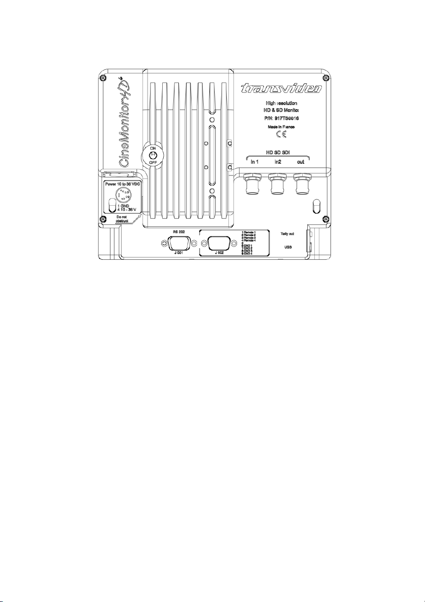
Figure 3 - CineMonitorHD3DView6 back (SDI Only)
Page 4

Page 5
Rev.0.0
CineMonitorHD3DView evolution
Jan 4th 2010
About
This Operator Manual describes the use of the TRANSVIDEO
CineMonitorHD3DView “evolution” family.
The first CineMonitor has been introduced to the Film Industry during year 1995.
The CineMonitorHD3DView “evolution” is our latest contribution to the Digital
Cinematography Stereoscopic world, including advanced decision tools for the
HD3D filmmaker.
The CineMonitorHD3DView evolution family includes the following products:
CineMonitorHD63DView evolution 6” HD 3DView Monitor
CineMonitorHD103DView evolution 10” HD 3DView Monitor
CineMonitorHD123DView evolution 12” HD 3DView Monitor
CineMonitorHD153DView evolution 15” HD 3DView Monitor
If the physical, electrical and optical characteristics of the products are different,
the user interface is the same.
Several configurations are optionally available for this family of products.
There is the choice at the order between several input boards, which gives
different functionalities described in this document. Some options can be not
implemented in your CineMonitorHD3DView.
It is possible to upgrade the CineMonitorHD3DView, for that, please contact your
local Transvideo representative.
The products described in this book are professional equipments; they are not
designed for consumer use. Utilization of these products implies knowledge of
basics in video signal management, HDTV and film making concept.
Page 5

Page 6
Rev.0.0
CineMonitorHD3DView evolution
Jan 4th 2010
Table of content
CONDENSED OPERATING INSTRUCTIONS................................................................................................................9
INTRODUCTION ............................................................................................................................................................10
Unpacking and Inspection..............................................................................................................................................10
Safety Inspection............................................................................................................................................................10
Product Overview ...........................................................................................................................................................11
Front Panel Controls and Indicators ......................................................................................................................... 11
Rear Panel Controls and Connectors.......................................................................................................................11
Installation.................................................................................................................................................................12
Instrument Positioning ..............................................................................................................................................12
Power Requirements ................................................................................................................................................13
OPERATION...................................................................................................................................................................14
Start-Up & Power............................................................................................................................................................14
Using the direct access functions...................................................................................................................................14
F1…F4............................................................................................................................................................................14
Using the menus.............................................................................................................................................................15
Direct functions description ............................................................................................................................................16
ENERGY MODE....................................................................................................................................................... 16
MARKERS ................................................................................................................................................................16
Rotating knob......................................................................................................................................................17
Measure (Waveform, Vectorscope, Histogram) .......................................................................................................18
Rotating knob......................................................................................................................................................20
Considerations about the use of measurement tools in 3DView mode..............................................................21
1. ZOOM.............................................................................................................................................................22
Arrows & Rotating knob ......................................................................................................................................22
ASPECT RATIO........................................................................................................................................................ 22
USER........................................................................................................................................................................ 23
INPUT .......................................................................................................................................................................25
ADJUST ....................................................................................................................................................................26
MENU FUNCTIONS .......................................................................................................................................................27
ADJUSTMENTS .......................................................................................................................................................27
HUE (TINT) .........................................................................................................................................................27
BRIGHTNESS.....................................................................................................................................................27
CONTRAST.........................................................................................................................................................27
SATURATION.....................................................................................................................................................27
BLUE CHECK........................................................................................................................................................... 27
COLORIMETRY........................................................................................................................................................27
MANUAL .............................................................................................................................................................27
Page 6

Page 7
Rev.0.0
CineMonitorHD3DView evolution
Jan 4th 2010
D56...................................................................................................................................................................... 28
D65...................................................................................................................................................................... 28
GAMMA.....................................................................................................................................................................28
GAMMA ADJUST................................................................................................................................................28
STANDARD 0.45 ................................................................................................................................................28
Use in LINEAR....................................................................................................................................................28
LOCK ........................................................................................................................................................................28
TOOLS......................................................................................................................................................................29
AUDIO.................................................................................................................................................................29
TIMECODE.........................................................................................................................................................30
COOKE LENS ..................................................................................................................................................... 31
FOCUS HELPER ................................................................................................................................................32
FRAMELINE........................................................................................................................................................32
HORIZON (if option installed)............................................................................................................................. 34
LIMITS.................................................................................................................................................................35
MAX LEVEL...................................................................................................................................................35
WHITE CLIPPING .........................................................................................................................................35
BLACK CLIPPING......................................................................................................................................... 35
MIN LEVEL....................................................................................................................................................35
SORIN’s MARKER ........................................................................................................................................35
SORIN’s MARHER WIDTH...........................................................................................................................36
OVEREXPOSURE: ON/OFF ........................................................................................................................36
SORIN’S MARKER: ON/OFF........................................................................................................................36
BLACK LIMITS: ON/OFF ..............................................................................................................................36
MEASUREMENT ................................................................................................................................................ 37
SIGNAL ANALYSIS.......................................................................................................................................37
OVEREXPOSURE: ON/OFF ........................................................................................................................37
SORIN’S MARKER: ON/OFF........................................................................................................................37
BLACK LIMITS: ON/OFF ..............................................................................................................................37
1 LINE............................................................................................................................................................37
12 LINES .......................................................................................................................................................37
ALL LINES.....................................................................................................................................................37
Background INTENSITY ...............................................................................................................................37
SPOT INTENSITY......................................................................................................................................... 37
RETICULE INTENSITY.................................................................................................................................37
TALLY.................................................................................................................................................................38
NORMAL.............................................................................................................................................................39
HORIZONTAL FLIP ............................................................................................................................................39
VERTICAL FLIP ..................................................................................................................................................39
PICTURE REVERSE .......................................................................................................................................... 40
AUTO REVERSE................................................................................................................................................40
AUTO FLIP VERTICAL ONLY............................................................................................................................40
3D..............................................................................................................................................................................41
GRID...................................................................................................................................................................41
MODE..................................................................................................................................................................42
COLORS............................................................................................................................................................. 42
FLOP...................................................................................................................................................................43
FLIP.....................................................................................................................................................................43
HORIZ SHIFT......................................................................................................................................................43
DISPLAY MODE.......................................................................................................................................................44
COLOR................................................................................................................................................................44
GREEN................................................................................................................................................................44
B&W ....................................................................................................................................................................44
TECHNICAL..............................................................................................................................................................44
CVBS STD SELECT........................................................................................................................................... 44
NTSC...................................................................................................................................................................44
REVERSE SCROLLING.....................................................................................................................................44
ACCESSORY......................................................................................................................................................45
COMPONENT RGB......................................................................................................................................45
COMPONENT YPrPb....................................................................................................................................45
Page 7

Page 8
Rev.0.0
CineMonitorHD3DView evolution
Jan 4th 2010
CVBS ............................................................................................................................................................. 45
VOLTAGE ALARM..............................................................................................................................................45
VOLTAGE DISPLAY.....................................................................................................................................45
VOLTAGE ALARM LEVEL............................................................................................................................45
VOLTAGE ALARM DISPLAY........................................................................................................................45
POSITION .....................................................................................................................................................45
EXIT TEMPO ......................................................................................................................................................45
LED DIMMER......................................................................................................................................................46
MEMORY..................................................................................................................................................................46
MEM 1 … MEM 4................................................................................................................................................46
SAVE.............................................................................................................................................................46
RECALL.........................................................................................................................................................46
PRESET..............................................................................................................................................................46
PRESET ALL INPUTS .................................................................................................................................. 46
PRESET SELECTED INPUT........................................................................................................................46
SERVICE & MAINTENANCE .........................................................................................................................................47
General...........................................................................................................................................................................47
Useful tips.......................................................................................................................................................................47
CLEANING................................................................................................................................................................47
FULL RESET............................................................................................................................................................47
Software and Firmware ..................................................................................................................................................48
Calibration.......................................................................................................................................................................48
Product Return................................................................................................................................................................48
ACCESSORIES..............................................................................................................................................................49
SPECIFICATIONS..........................................................................................................................................................51
CONNECTORS.............................................................................................................................................................. 53
TRANSVIDEO EQUIPMENT LIMITED WARRANTY ....................................................................................................54
Page 8

Page 9
Rev.0.0
CineMonitorHD3DView evolution
Jan 4th 2010
WARNING and CAUTION
WARNING: There is very high voltage inside of the component. Risk of injury
or death.
WARNING: This product must be used in a correct grounded electrical
environment; ground defects can create severe problems to the equipment, the
picture quality and even cause danger for the user.
WARNING: Copyright law and international treaties protect this product, its
design and its software. One or several international patents apply to the
“CineMonitorHD3DView evolution”.
Unauthorized reproduction or distribution of this product or its design or its
software or any portion of them, may result in severe civil and criminal
penalties, and will be prosecuted to the maximum extent possible under the
law.
CAUTION: Warranty is void is the product is opened. The unit contains
electrostatic sensitive devices, which can be damaged or destroyed if you touch
them. Refer to the standard ESD procedures before disassembly of the
component. Very high voltage are present in the unit, there is some risk of
electric shock if opened by a non-accredited technician.
Condensed Operating Instructions
① Connect an adapted power supply to the XLR connector or a battery if
any socket available.
② Connect a video source to the input
③ Switch on the monitor with the back switch
④ Select the correct input with INPUT SEL
For more information, please read the manual in SECTION III “OPERATION”
Page 9

Page 11
Rev.0.0
CineMonitorHD3DView evolution
Jan 4th 2010
Product Overview
Front Panel Controls and Indicators
Rear Panel Controls and Connectors
Page 10

Page 12
Rev.0.0
CineMonitorHD3DView evolution
Jan 4th 2010
Installation
The CineMonitorHD3DView must be securely fixed on the camera or on the
location of use. TRANSVIDEO manufactures high quality brackets and
accessories for the comfort of use and security for the equipment and user.
Do not use the monitor with loose fixation or damaged brackets it is a question
of security for yourself and other persons working on the same location.
Several fixation points have been added to this equipment for secured
professional use.
① A slide with a ¼-20” nut is delivered as standard equipment with the
product. This slide is fixed on the bottom of the monitor.
② One or several optional slides can be attached to the sides, back or top
of the monitor. 2 x M4 screws attach the slides. Several TRANSVIDEO’s
accessories can be fixed in these positions; this mounting system is generic for
Transvideo since 1990.
③ One square of 20mm accepts 4xM3 screws.
Instrument Positioning
The CineMonitorHD3DView needs to be in a ventilated area to be normally
cooled.
Long use in closed environment without ventilation can damage the monitor.
Never use the monitor in a plastic bag.
Never use the monitor in full sun with a Raincover.
Page 11

Page 13
Rev.0.0
CineMonitorHD3DView evolution
Jan 4th 2010
Power Requirements
Only DC Voltage powers this product.
AC voltage can be used with an appropriate AC/DC converter
Recommended power adaptors:
CineMonitorHD63DView evolution Transvideo AL24
CineMonitorHD103DView evolution Transvideo AL80
CineMonitorHD123DView evolution Transvideo AL80
CineMonitorHD153DView evolution Transvideo AL80
The input power voltage range is extremely wide from 10 to 36 V DC (except
specified differently).
The power consumption slightly varies with the input voltage, the operating
temperature and the configuration of the product.
The power supply is protected against reverse polarity.
Over voltage may cause severe damages to the equipment.
For safety of use the CineMonitorHD3DView family feature a galvanic insulation
of the DC input. Do not connect the power ground to the chassis of the monitor
or to the metallic body of the power connector to keep the galvanic insulation.
The galvanic insulation is rated at 1000VDC. The chassis of the monitor is
connected to the video ground.
Page 12

Page 14
Rev.0.0
CineMonitorHD3DView evolution
Jan 4th 2010
Operation
Start-Up & Power
The ON/OFF Switch is placed on the back of the monitor.
The product needs a certain time to reach its nominal brightness.
This time can vary with the temperature.
When using the optional Battery Holder, the switch of the battery holder
overpasses the switch of the monitor.
In OFF position, the power consumption is null.
WARNING RISK OF FIRE: It is always recommended to remove the power
source from the monitor when you do not use it and/or when you travel.
Especially if you place the monitor in a closed environment (bag, box, …)
Using the direct access functions
Several direct functions are available from the keypad.
One short press on the pad allows access to the functionalities.
One long press (more than 2 seconds) on the pad allows access to the optional
functionalities for the related function (if any).
The rotating knob is a rotary encoder with a push function, it is used to access
and navigate in the menus, adjust some parameter values, validate and exit
functions by pushing it.
A short push when on “EXIT” exits of the current menu to the previous level (if
any) a long push exits from the menu.
F1…F4
One long press (more than 2 seconds) on the direct function pad allows to
access to the optional functionalities for the related function (if any).
Depending of the function, options and environment, the content of F1 … F4 can
vary. Pressing the pad just under the engraving will activate or deactivate the
sub-function. The activated sub-function is highlighted on the menu by an
orange text, un-activated function is displayed in white.
In some specific case, F4 can extend the selection to a second page of submenu.
Page 13

Page 15
Rev.0.0
CineMonitorHD3DView evolution
Jan 4th 2010
Using the menus
The menu gives access to functionalities that do not have direct access from the
keypad.
The rotating knob is used to navigate in the menu structure.
Pushing the rotating knob allows to access to the function sub-menu.
Exit of the menu by selecting EXIT or by automatic temporization (temporization
can be adjusted in the TECHNICAL Menu)
Some feature described in this manual could be optional.
If your monitor do not show the feature described in this manual, please check
first if you bough the described option. You can contact your distributor to
upgrade your product and/or to install some optional tools.
Page 14

Page 16
Rev.0.0
CineMonitorHD3DView evolution
Jan 4th 2010
Direct functions description
ENERGY MODE
Allows switching between different modes:
FULL BRIGHT: Maximum brightness and power consumption, the color
calibration is deactivated.
CALIBRATED: Standard mode, the brightness and white point are
calibrated according to the settings of MENU/COLORIMETRY
USER: Brightness is adjustable from 10% to 100%, color
calibration is preserved. Allows having a reduced power mode between two
takes.
F1: D56
F2: D65
F3: MANUAL (Adjustable in MENU/COLORIMETRY/)
It is necessary to wait a few seconds after pressing the pad before loading of the
correct lookup table
MARKERS
Displays the markers selected with F1…F4
Not active when the ZOOM or FORMAT 2.40:1 are selected
This menu is contextual; some functions can be unavailable depending of the
input format.
F1: 4:3
F2: 14:9
F3: 16:9
F4: ->
Next page
FI: SAFE area
F2 3D Grid*
F4: <-
* The grid is available in 3DView mode and is a specific tool for stereographic
work which have been developed in cooperation with Alain Derobe AFC,
Page 15

Page 17
Rev.0.0
CineMonitorHD3DView evolution
Jan 4th 2010
Stereographer and 3D consultant. This grid is mainly used to adjust the far planes
parallax to the target screen size.
It is a vertical parallel grid with adjustable width between the lines.
In zoom mode the grid is sized to the native resolution. The grid can be adjusted
in MENU/3D/GRID/… or during the selection and call of the function through the
MARKER direct access pad.
Rotating knob
To adjust the offset of the 3D Grid when pushing shortly on MARKER and with
grid selected. The offset of the grid, or horizontal positioning, is adjustable of
plus or minus half of the value of the grid.
By pressing more than 3 seconds the “MARKER” pad when the grid is displayed,
it is possible to modify the step of the grid from 1 to 123 pixels. During selection,
it is possible to adjust the width of the grid with the rotating knob.
Page 16

Page 18
Rev.0.0
CineMonitorHD3DView evolution
Jan 4th 2010
Measure (Waveform, Vectorscope, Histogram)
Displays the selected measurement tools.
The brightness of the reticule and of the spot can be adjusted in the TECHNICAL
MENU
White and black clipping alert can be configured in MENU/TOOLS/LIMITS/, the
same limits are used for the waveform monitor and the histogram representation.
Setting these limits is useful to have a visual alert on the waveform and
histogram representation of the video signal if there is a risk of overexposure or
of loss of black details.
F1: WAVEform
F2: HISTOgram
F3: VECTORscope
Selecting F1:WAVE gives access to an other sub-menu:
F1: LINE
Displays one a single spot, Y, Red, Green or Blue
Page 17

Page 19
Rev.0.0
CineMonitorHD3DView evolution
Jan 4th 2010
F2: PARADE
Displays Y, R, G , B, Pr & Pb in parade mode.
Available modes:
Y R G B / Y G B R
R G B / G B R
Y Cr Cr
F3: FRAME
Displays Y, R, G or B in frame mode. (also named sweep mode)
The content of one frame/picture is displayed.
Selecting F2:HISTOGRAM displays directly the representation:
F4: Return to the previous menu.
Selecting F3:VECTOR displays directly the representation:
Page 18

Page 20
Rev.0.0
CineMonitorHD3DView evolution
Jan 4th 2010
Rotating knob
When a measurement tool is displayed. Pressing the WFM pad gives the
possibility to adjust the representation by using the rotating knob.
Histogram : Adjustment of the scale of the histogram
Page 19

Page 21
Rev.0.0
CineMonitorHD3DView evolution
Jan 4th 2010
Waveform : 3 sizes of waveform are available
The background transparency in overlay mode can be adjusted
in MENU/MEASURE
Considerations about the use of
measurement tools in 3DView mode
When using the 3DView mode the tool’s spot displays the two inputs
simultaneously. It is valid for the Waveform, Histogram and Vectorscope.
To identify clearly the source, each spot uses a specific color.
The colors used are the same as those selected for the Anaglyph/Monochrome
mode.
The selection of the color is done in MENU/3D/…
i.e. Using the HISTOGRAM with RED CYAN colors will display input 1 in RED and
input 2 in CYAN. The common values of the HISTOGRAM will be displayed in
white, the differences in BLUE or CYAN.
i.e. Using the HISTOGRAM with RED/BLUE colors will display input 1 in RED and
input 2 in BLUE. The common values of the HISTOGRAM will be displayed in
MAGENTA, the differences in RED or BLUE.
Page 20

ZOOM
Displays the HD picture in full resolution mode (pixel to pixel).
Depending of the input format, the magnification ratio can be different.
Displays the SD picture in full screen. In this case there is an important
magnification ratio applied to the original picture, the resultant picture includes
created pixels and lines and cannot be considered as a proof. In this mode the
waveform will be superimposed to the picture.
Arrows & Rotating knob
In zoom mode arrows move the picture on Top/Bottom, Left/Right positions; Fine
adjustment can be made by rotating the rotating knob.
A long push on the ZOOM pad centers the picture, the next push sends back to
the full picture display.
During the zoom mode a pictogram is displayed in the right side of the tool zone.
This pictogram indicates the relative position of the magnified zone in the original
picture.
ASPECT RATIO
Allows the change of aspect ratio between:
1.33:1 4/3 SD only
1.78:1 16/9 HD & SD
2.40:1 HD & SD
Rev.0.0
CineMonitorHD3DView evolution
Page 22
Jan 4th 2010
Page 21

Page 23
Rev.0.0
CineMonitorHD3DView evolution
Jan 4th 2010
USER
User configurable input. This pad gives access to the function pre-selected in
F1…F4 menu.
Page 1
F1: STATUS
Displays the status of the monitor and the input voltage from the power
supply or the battery (for V-Lock equipped monitors)
F2: FOCUS *
Activates through the USER control the FOCUS HELPER function as
programmed in MENU/TOOLS/FOCUS HELPER.
F3: EXPO *
Access to the OverExposure Control as configured in
MENU/TOOLS/LIMITS/…
F4: ->
Jump to next page
Page 2
F1: MEM
Access to the Memory menu
F2: Horizon**
F3: ZONE
Allows to adjust the acquisition zone for the waveform and vectorscope.
Active when “1 line” or “12 lines” are selected.
F4: < Jump to previous page
* FOCUS and EXPO can be activated simultaneously.
If both are activated, pressing USER set up:
a) FOCUS + EXPO
Page 22

Page 24
Rev.0.0
CineMonitorHD3DView evolution
Jan 4th 2010
b) FOCUS
c) EXPO
d) Nothing
** The horizon is optional, if the horizon is not implemented, this menu will
not appear.
Page 23

Page 25
Rev.0.0
CineMonitorHD3DView evolution
Jan 4th 2010
INPUT
Selects the input and gives access to the 3DView mode.
At selection, the format of the video is displayed
When no signal is available, displays “NO SYNC”
F1…F4 Selection of active inputs (Input board dependant)
CineMonitorHD 3D View
F1: SDI 1
F2: SDI 2
F3: 3D View
Pressing F1…F4 activates or not the selected input. An active input appears in
orange, an inactive in white. An inactivated input cannot be selected by the
“INPUT”.
Attention:
To use the 3D View mode, the cameras must be genlocked.
The CineMonitorHD 3DView gives the 3D functions with the following
formats:
1080i, PsF
720p
The 3D functions are not available with 1080p even if it is possible to
visualize independently the video signal.
Page 24

Page 26
Rev.0.0
CineMonitorHD3DView evolution
Jan 4th 2010
ADJUST
Select HUE (NTSC only), BRIGHTNESS, CONTRAST, SATURATION by pressing
the pad.
Adjust the value by rotating the rotating knob
Validate by pushing the rotating knob
Important:
The settings are different for each input.
All settings are stored in setup memories.
There is one memory per input.
That means you can setup the ACCessory input differently of the SDI input. It is
useful with some specific digital cameras offering a viewfinder menu and a HD
SDI preview output.
Page 25

Page 27
Rev.0.0
CineMonitorHD3DView evolution
Jan 4th 2010
MENU FUNCTIONS
ADJUSTMENTS
HUE (TINT)
Adjustment of the color phase.
This adjustment is only usable in NTSC when the monitor is equipped with a
CVBS analog input.
Values from -90° to +90° each step 1°
BRIGHTNESS
Setup the black level of the signal from -174mV to +174mV from the nominal
position.
CONTRAST
Setup the gain of the video signal (Black to White level) from –100% to +100%
around of the nominal position.
SATURATION
Setup the color saturation of the signal from -100% to +100% around of the
nominal position.
BLUE CHECK
Sets the monitor in BLUE ONLY mode.
This mode is used to calibrate the monitor with an incident color bar.
COLORIMETRY
MANUAL
Allows the manual adjustment of RGB gain (from 0 to 2, nominal 1.00) and offset
of the black (-127mV to + 126mV, nominal 0 mV).
The nominal value in manual mode corresponds to the D65 setup.
WARNING: In MANUAL there is a risk of displaying wrong colors; this option
must be used carefully.
Page 26

Page 28
Rev.0.0
CineMonitorHD3DView evolution
Jan 4th 2010
D56
Sets the monitor for a white point DAYLIGHT 5600
CIE 1931 Coordinates:
x: 0.3310
y: 0.3460
D65
Sets the monitor for a white point DAYLIGHT 6500
CIE 1931 Coordinates:
x: 0.3127
y: 0.3290
GAMMA
Adjust the grey point of the monitor according to the formula
Vc =Vs
1
"
#
$
%
&
'
(
Where Vc represents the displayed signal and Vs is the incident signal.
The correction is applied with a simulated response of CRT.
GAMMA ADJUST
Allows continuous adjustment 0.3 < γ < 2.5
The indicated value is for the corrected signal and do not indicate the monitor’s
gamma.
STANDARD 0.45
Set the monitor to reproduce a signal corrected by a γ of 0.45
Use in LINEAR
To use the monitor with a linear signal (non γ corrected), adjust the value to 1.00
LOCK
The lock function prevents errors after configuration and calibration of the
monitor.
Page 27
Page 29
Rev.0.0
CineMonitorHD3DView evolution
Jan 4th 2010
When the function is activated, “LOCK” is displayed on the screen at each
attempt to enter in the menu or to access a direct function.
To overpass the function, the user must keep pressing the rotating knob for more
than 5 seconds. It removes the function.
TOOLS
The tools make the richness of the CineMonitorHD3DView evolution.
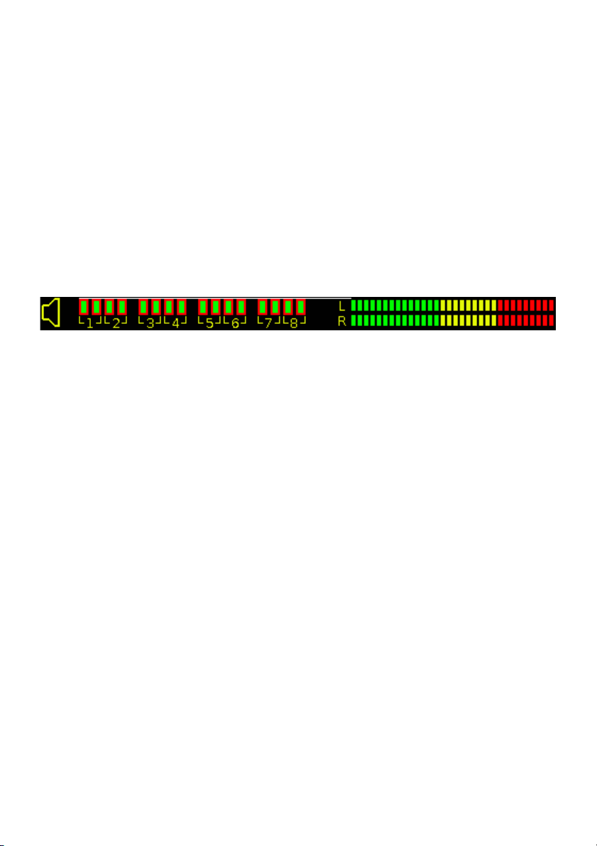
AUDIO
Displays the SDI embedded audio presence and a bargraph showing one audio
pair on the 8 possible pairs.
AUDIO: ON/OFF
Activates or deactivates the function
CHANNEL PAIR: X
Selection of the pair displayed on the bargraph with the rotating knob.
POSITION
Allows placing the tool in different position of the screen by using arrows
and the rotating knob when USER is selected in the menu.
DEFAULT replaces the tool at the factory preset.
Page 28

Page 30
Rev.0.0
CineMonitorHD3DView evolution
Jan 4th 2010
TIMECODE
Displays the embedded VITC & or 2 or LTC Timecode.
TIMECODE: ON/OFF
Activates or deactivates the function
ATC: AUTO, LTC, VITC1, VITC2
Selection of the displayed VITC, in AUTO mode the first time code
present is displayed (1: LTC, 2: VITC1, 3: VITC2)
POSITION
Allows placing the tool in different position of the screen by using arrows
and the rotating knob when USER is selected in the menu.
DEFAULT replaces the tool at the factory preset.
Page 29

Page 31
Rev.0.0
CineMonitorHD3DView evolution
Jan 4th 2010
COOKE LENS
Displays the datas of a i/lense.
Accepted lenses: COOKE S4/I, COOKE 5
MODULE: ON/OFF
Activates or deactivates the function
ZONE: OP+ASSIT, ASSIST, OFF
The COOKE 5 is able to light the focus and iris scales on the operator
and/or the assistant side.
Selection of the lighted zones
OPERATOR + ASSISTANT or ASSISTANT ONLY
This function is available only if a COOKE 5 lens is detected.
BRIGHTNESS
Adjust the brightness of the LEDs on a COOKE 5 lens
This function is available only if a COOKE 5 lens is detected.
UNIT
Selection of METRIC or IMPERIAL
FILM
Selection of 16mm or 35mm
Page 30

Page 32
Rev.0.0
CineMonitorHD3DView evolution
Jan 4th 2010
FOCUS HELPER
Activates a precise focus helper displaying infocus zones with colored dots. The
focus helper is based on a complex multidimensional digital filter.
When 3DView mode is activated, the infocus zone of each camera is displayed
with a specific color.
The color is defined in MENU/3D/COLOR/…
The focus helper can be remoted by the USER pad, the settings must have been
previously configured. (Press long time USER, then set the function with F1…F4)
COLOR
Selection of the in focus zone color.
Red, Green, Blue, Yellow, Magenta, Cyan, Black or White.
LEVEL
Adjustment of the selectivity of the filter.
OFF, 1 to 5 (5 gives the highest effect)
FRAMELINE
This option allows displaying one locating cross and up to 3 programmable
frames with or without center marker and a matting generator.
The menu shows different levels:
CROSS
CROSS ON/OFF
Activation of the cross
COLOR
Selection of the color of the lines
WIDTH
Selection of the width of the lines
V POS
Move the vertical position of the cross
H POS
Move the horizontal position of the cross
FRAME 1
FRAME 1 ON/OFF
Page 31

Page 33
Rev.0.0
CineMonitorHD3DView evolution
Jan 4th 2010
Activation of the frame
CENTER ON
Activation of the center cross
COLOR
Modification of the color of the frame
DOT
Modification of the structure of the frame
SEND TO CENTER
Send the selected frame to the center of the screen.
V SIZE
Size of the frame (bottom part is moving)
H SIZE
Size of the frame (right part is moving)
V POS
Vertical position of the frame
H POS
Horizontal position of the frame
V ZOOM
Vertical homothetic modification of the frame
H ZOOM
Horizontal homothetic modification of the frame
FRAME 2
…
FRAME 3
…
SEND ALL TO CENTER
Send all frames to the center of the screen.
BCKGND COLOR (Matting Generator)
Change the background color outside of the frames.
Page 32

Page 34
Rev.0.0
CineMonitorHD3DView evolution
Jan 4th 2010
HORIZON (if option installed)
This option allows displaying a virtual horizon on the screen.
The menu shows different levels:
SENSOR
Toggles between INTERNAL and BETZ.
In BETZ position it is possible to connect an external electronic bubble
designed by Betz Tools. A specific cable is needed to power and remote
the bubble through J001.
Transvideo do not support this third party equipment.
http://www.betz-tools.com/monitor_electronic-bubble.php
NORMAL / REVERSE
Toggles the action of the horizon, normal or reversed.
SENSITIVITY
Adjusts the sensitivity of the virtual horizon (True, X2, X4, X8, X16).
STYLE
Allows to display or not the Horizon on the monitor.
Selects the style of the virtual horizon (6 different models).
Selects the presence or not of the horizon.
0 CAL
Set the horizon to 0
A temporization of 5 seconds allows stabilizing the position of the
system.
Pushing the rotating knob during calibration exits the timing.
POSITION
Allows placing the tool in different position of the screen by using arrows
and the rotating knob when USER is selected in the menu.
DEFAULT replaces the tool at the factory preset.
Page 33

Page 35
Rev.0.0
CineMonitorHD3DView evolution
Jan 4th 2010
LIMITS
The limits menu is a very important item of the CineMonitorHD3DView family.
It is used to setup the characteristics of the camera you are using and some
safety levels which will be used in different tools.
MAX LEVEL
Set up the upper clipping level (White).
Adjustment goes from 100 IRE to 108 IRE
All information over the limit will be displayed in red on the waveform and the
overexposed zone on the picture if the “overexposure control” is activated.
Default value: 107
WHITE CLIPPING
Set up the upper clipping level (White) on the waveform.
Adjustment goes from 70 IRE to 108 IRE
The upper value is limited by the MAX LEVEL setting.
All information over the limit will be displayed in orange on the waveform and the
overexposed zone on the picture if the “overexposure control” is activated.
Default value: 100
BLACK CLIPPING
Set up the lower clipping level (Black) on the waveform.
Adjustment goes from -7 IRE to 35 IRE
The lower value is limited by the MIN LEVEL setting.
All information below the limit will be displayed orange on the waveform and dark
blue on the underexposed zone on the picture if the “black limits” is activated.
Default value: 10
MIN LEVEL
Set up the low clipping level (Black.
Adjustment goes from -7 IRE to 35 IRE.
All information below the limit will be displayed red on the waveform and medium
blue on the underexposed zone on the picture if the “black limits” is activated.
Default value: 0
SORIN’s MARKER
Adjust the central value of the marker in IRE.
Page 34

Page 36
Rev.0.0
CineMonitorHD3DView evolution
Jan 4th 2010
SORIN’s MARHER WIDTH
Adjust symmetrically the thickness of the marker within the limits of the white
and black clipping values.
About the Sorin’s marker:
Sorin Dragoi RSC is a famous Romanian Director of Photography, he suggested
this tool, which he is using mainly to check the exposure on skin tone. The Sorin’s
marker is used to see all light equivalent zones, i.e. to see the 0 stop zone of the
picture.
OVEREXPOSURE: ON/OFF
Switch ON or OFF the overexposure control.
The MAX LEVEL and the WHITE CLIP are displayed in false colors when
activated.
SORIN’S MARKER: ON/OFF
Switch ON or OFF the Sorin’s Marker.
The Sorin’s area is displayed in false colors when activated.
BLACK LIMITS: ON/OFF
Switch ON or OFF the black limits control.
The MIN LEVEL and the BLACK CLIP are displayed in false colors when
activated.
Page 35

Page 37
Rev.0.0
CineMonitorHD3DView evolution
Jan 4th 2010
MEASUREMENT
This option allows different setups for the video measurement tools.
The settings apply to all video measurement tools except the histogram, which
represents always the full picture.
SIGNAL ANALYSIS
Select 8 bits if the SIGNAL is 8 bits. Default value is 10 bits
OVEREXPOSURE: ON/OFF
Switch ON or OFF the overexposure zoning on the measurement tools.
SORIN’S MARKER: ON/OFF
Switch ON or OFF the Sorin’s Marker zoning on the measurement tools.
BLACK LIMITS: ON/OFF
Switch ON or OFF the black limits zoning on the measurement tools.
1 LINE
Displays the measurement of one line selected with the rotating knob.
12 LINES
Displays the measurement of a group of 12 lines, the first line is selected with the
rotating knob.
ALL LINES
Displays the measurement of the whole picture.
Background INTENSITY
Adjusts the overlay transparency behind the measurement tools when displayed
in front of the picture.
SPOT INTENSITY
Adjusts the brightness of the waveform spot
RETICULE INTENSITY
Adjusts the brightness of the waveform reticule
Page 36

Page 38
Rev.0.0
CineMonitorHD3DView evolution
Jan 4th 2010
TALLY
This option allows the use of the TALLY function.
The Tally is activated via the pin 1 and 6 of the GPI connector J002.
The menu shows different levels:
ACTIVE LOW/HIGH
Sets the state for TALLY ON
LED ON/OFF
Activates/deactivates the TALLY LED on the front panel.
TALLY BLINKING/FIX
Sets the active mode in TALLY ON
STYLE
Selects the style of the TALLY, including the TALLY FRAME which is
active on FRAME3 of the FRAMELINE (The FRAMELINE option must be
installed to use this mode.
Page 37

Page 39
Rev.0.0
CineMonitorHD3DView evolution
Jan 4th 2010
PICTURE FX
NORMAL
Restores the standard display
HORIZONTAL FLIP
Returns the picture horizontally.
VERTICAL FLIP
Returns the picture vertically.
Page 38

Page 40
Rev.0.0
CineMonitorHD3DView evolution
Jan 4th 2010
PICTURE REVERSE
Returns the picture horizontally and vertically.
AUTO REVERSE
Returns the picture
automatically if the
monitor is up side
down.
AUTO FLIP VERTICAL ONLY
Returns the picture
automatically (vertical
axis only) if the monitor
is up side down
Page 39

Page 41
Rev.0.0
CineMonitorHD3DView evolution
Jan 4th 2010
3D
This menu is only visible in 3DView mode
Warning: In the following description we assume that the left eye camera is
always wired on SDI1 and the right eye camera always on SDI2.
GRID
GRID
ON/OFF
Activates, deactivates the grid.
The grid can be activated also in MARKER direct access pad.
WIDTH
Adjusts the separation between the vertical lines from 6 to 123 pixels.
The number of pixels is indicated on the incident picture, not on the
screen, except when in ZOOM mode.
OFFSET
Shifts the grid left or right of half of the WIDTH value.
COLOR
Sets the color of the grid
AREA
Allows to clear the center of the grid in order to see the only the picture.
From 100% where the picture is fully covered to 5% where only the
barders are covered.
INTENSITY
Sets the brightness of the grid
DENSITY
Sets the density of the lines from dots to solid.
EXIT
Page 40
Page 42
Rev.0.0
CineMonitorHD3DView evolution
Jan 4th 2010
MODE
4 possibilities are available by pressing the blue knob when the line is
highlighted.
When used, the settings of this menu overpass the settings of “DISPLAY MODE”
menu settings
SHUTTER GLASSES
The 2 pictures are displayed alternatively.
The optional Shutter Glasses module synchronizes the shutter glasses.
ANAGLYPH
Only the selected monochromatic component of left camera (SDI 1) is displayed
Only the complementary components of right camera (SDI 2) are displayed
The pictures are interleaved.
To visualize the 3D effect, it is necessary to use specific glasses.
The colors used in this mode depend of the settings of COLORS
MONOCHROME
The left camera (SDI 1) and right camera (SDI 2) are displayed in monochrome.
The colors used in this mode depend of the settings of COLORS
This mode is useful to visualize the fringes between the 2 pictures.
COLOR
The left camera (SDI 1) and right camera (SDI 2) are displayed in full color.
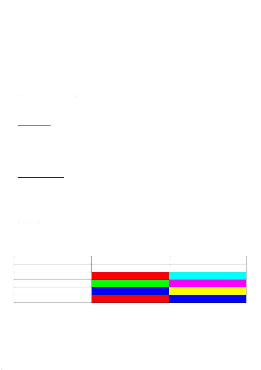
COLORS
4 modes are available.
Eye
Left Eye
Right Eye
Input
SDI 1
SDI 2
Mode 1
RED
CYAN
Mode 2
GREEN
MAGENTA
Mode 3
BLUE
YELLOW
Mode 4
RED
BLUE
To visualize correctly the 3D effect in ANAGLYPH, it is necessary to use the
color-coded glasses accordingly to the selected mode.
Page 41

Page 43
Rev.0.0
CineMonitorHD3DView evolution
Jan 4th 2010
FLOP
The FLOP is a vertical inversion of the picture
A push then a rotation of the knob activates or
deactivates the FLOP of the left camera (SDI1),
right camera(SDI2) or both cameras (SDI1 & SDI2)
A push validates the choice.
FLIP
The FLOP is a horizontal inversion of the picture (mirror effect)
A push then a rotation of the knob activates or
deactivates the FLIP of the left camera (SDI1),
right camera(SDI2) or both cameras (SDI1 & SDI2)
A push validates the choice.
It is possible to activate simultaneously the FLIP and the FLOP
HORIZ SHIFT
Turning the blue knob when the line is selected allows shifting the SDI2 picture.
Attention: this function shall be used carefully as misinterpretation on the result
may occur.
Page 42

Page 44
Rev.0.0
CineMonitorHD3DView evolution
Jan 4th 2010
DISPLAY MODE
When used, the settings of this menu overpass the settings of “3D/MODE” menu
settings
COLOR
Standard mode, displays the picture with 16 millions colors, 256 gray levels.
GREEN
Display the picture in green color only.
TINT and SATURATION are not working in this mode.
This mode has been invented by TRANSVIDEO in 1990 and is used since this
time in Film & Night Vision systems.
B&W
Displays the picture with 256 gray levels.
TINT and SATURATION are not working in this mode.
TECHNICAL
CVBS STD SELECT
Setting of the video composite standard.
AUTO DETECT Default value
PAL BGHID
NTSC 3.58
With some color video-assist unit it may appears that the picture will be
displayed in black and white, in this case please select the appropriate standard.
NTSC
Setting of NTSC Japan (black 0 IRE) or US (black 7.5 IRE).
Rotating the rotating knob to the requested standard does the setting.
REVERSE SCROLLING
Allows to reverse the rotating knob incrementation.
Page 43

Page 45
Rev.0.0
CineMonitorHD3DView evolution
Jan 4th 2010
ACCESSORY
Setting of the accessory input (when available)
An appropriate cable must be used.
COMPONENT RGB
HD or SD RGB signal with composite synchronization on the green channel is
allowed.
COMPONENT YPrPb
HD or SD YPrPb signal is allowed.
CVBS
Composite video signal is allowed.
VOLTAGE ALARM
VOLTAGE DISPLAY
ON/OFF
Displays constantly the voltage present on the power connector.
VOLTAGE ALARM LEVEL
Sets the threshold voltage from 10VDC to 36VDC.
Under this voltage an alert can be displayed on screen.
VOLTAGE ALARM DISPLAY
Activates VOLTAGE ALARM. When activated the battery pictogram is displayed
in red if the voltage of the power supply goes under the threshold setting.
POSITION
Allows placing the tool in different position of the screen by using arrows and the
rotating knob when USER is selected in the menu.
DEFAULT replaces the tool at the factory preset.
EXIT TEMPO
Setting of the auto exit temporization from SLOW to FAST
Page 44

Page 46
Rev.0.0
CineMonitorHD3DView evolution
Jan 4th 2010
LED DIMMER
Dimming of the brightness of the “POWER ON” Led, it is possible to switch of
completely the “POWER ON” Led.
MEMORY
MEM 1 … MEM 4
4 user memories per input (ANALOG, SDI Accessory) are available to save user’s
configurations.
SAVE
SAVE the current user set-up in the memory.
All configuration except INPUT SEL is stored in the memory, including:
-Picture settings
-Tools settings
-Framing options
RECALL
Recall the settings stored in the memory.
The standard settings a factory loaded in this memory, they will be replaced at
the first SAVE from the user.
PRESET
Set the default values in the setting registers.
PRESET does not erase the user presets.
PRESET ALL INPUTS
Presets the active input only
PRESET SELECTED INPUT
Presets the active input and other inputs of the monitor.
Page 45

Page 47
Rev.0.0
CineMonitorHD3DView evolution
Jan 4th 2010
Service & Maintenance
General
Please read carefully the chapter « TRANSVIDEO Equipment Limited Warranty »
about the warranty given by TRANSVIDEO S.A. on the equipment described in
this manual.
For repairs after the warranty period, you can refer to your local TRANVIDEO
Distributor/retailer or use the following procedure.
Useful tips
CLEANING
The painting of the CineMonitorHD3DView is resistant to general cleaners and
solvents. Do not use abrasive products to clean the CineMonitorHD3DView.
The front glass is a high quality optical part. A metallic multi-layers vacuum
deposit makes the anti-reflection coating. Do not use abrasive or acid cleaners.
The microfiber cloth delivered with the CineMonitorHD3DView is strongly
recommended to clean the glass. Remove dust and particles of the glass before
using the cloth. No liquid is normally necessary. If there is some dirt on the
screen, it is possible to remove it with clean warm water.
The microfiber cloth collects grease particle in its structure. It is necessary to
wash it when necessary with water and soap.
The microfiber cloth is orderable as spare part (see accessories)
FULL RESET
In case of need, it is possible to fully reset the CineMonitorHD3DView.
Connect the monitor to a power source
Switch off the monitor with the power switch on the back
Press the “adjust” pad
Switch on the monitor keeping pressed the “adjust” pad until the display shows
“FULL RESET”
This procedure totally erases all user setup in the memories.
Page 46

Page 48
Rev.0.0
CineMonitorHD3DView evolution
Jan 4th 2010
Software and Firmware
The software, firmware and hardware version are indicated at the startup on the
screen. This information is useful to keep in case of need for service purpose.
Calibration
The white point of the monitor is individually calibrated in factory for D65 and
D56.
The calibration doesn’t need to be performed except after some specific service
operation as the replacement of the backlight unit or if you need to match a large
inventory of CineMonitorHD3DView after hundreds hours of use.
To perform the calibration, you need to send the product(s) to the factory.
Product Return
For technical operation you can return the product to the factory.
Previously you have to ask for a RAN (Return Authorization Number)
Please provide the following information:
➀ Product type
➁ Model
➂ Serial Number
➃ Purpose of the return
You can contact us by:
Email [email protected]
Fax +33 2 3260 1479
Phone +33 2 3232 2761
Then send the product to the following address :
TRANSVIDEO
RAN # _ _ _ _ _ _ _
ZI - Rue Francois Arago
27130 Verneuil sur Avre
France
You are responsible for the way of shipment and the insurance of your product.
It is strongly recommended to inform us of the Tracking Number of your
shipment followed by the RAN. By this way we will be able to follow the
shipment.
Page 47
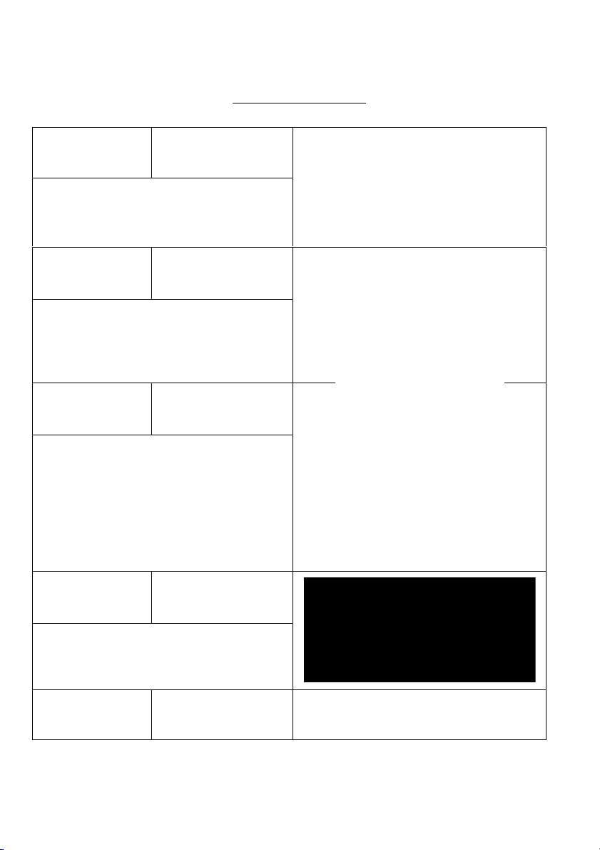
Accessories
Slide P/N 918TS0127
The Slide includes a ¼-20 nut.
Can be attached with 2 x M4 on left,
right, top and back of the
CineMonitorHD3DView
Clamp for Slide P/N 918TS0131
Firmly secures the
CineMonitorHD3DView on a Spigot.
3D SWING ARM
Strong with
Clamp for slide
Includes a Clamp for slide, adapted
on a 3D-SwingArm, reinforced for the
CineMonitorHD3DView, a 3/8-16
thread allows to fix the system to the
camera.
(adapters exist for ¼-20 and metric
Ikegami cameras.
P/N 918TS0148
Cardon Handle P/N 918TS0151
This carbon handle fits on the
Shoulder strap pins.
Shoulder strap
pin (2 per pack)
Rev.0.0
CineMonitorHD3DView evolution
P/N 918TS0143
Page 49
Jan 4th 2010
Page 48
Page 50
Rev.0.0
CineMonitorHD3DView evolution
Jan 4th 2010
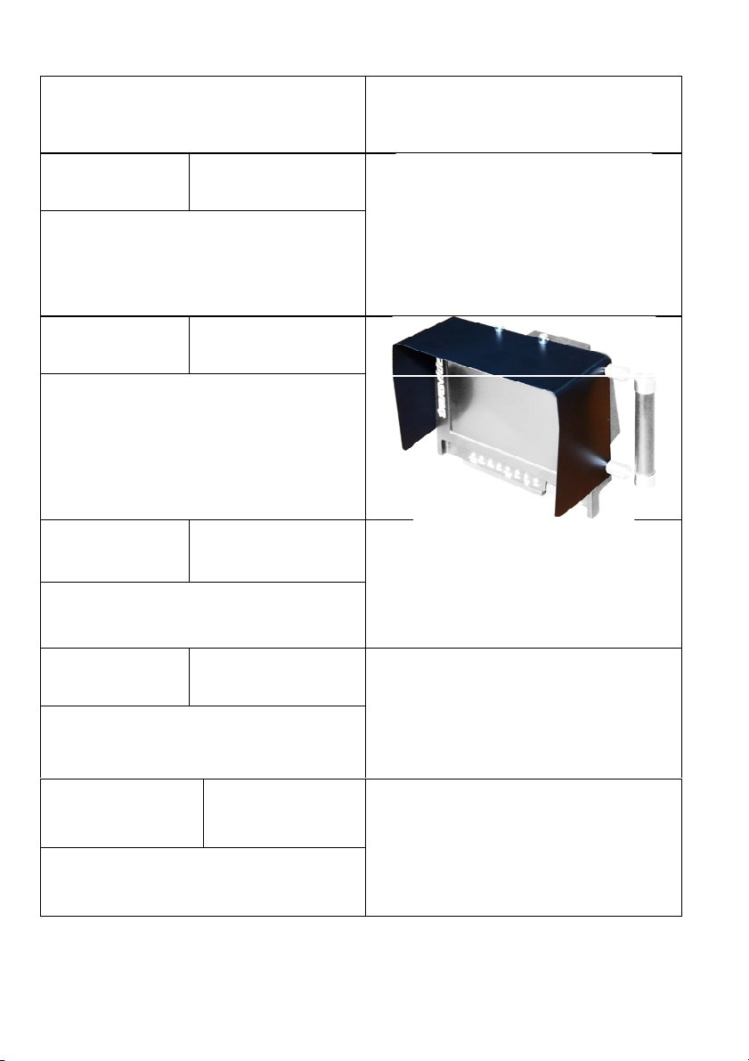
Sun & Night
Hood
6” P/N 918TS0135
8” P/N 918TS0142
High Quality Sun & Night Hood with
movable/removable flap.
Allows using Petrol, Kata or PortaBrace shoulder straps.
Light Hood
6” P/N 918TS0161
8” P/N 918TS0150
Light Lexan® hood to use on
Steadicam applications.
Battery Back
P/N 918TS0137
Standard version with V-mount.
Available with PAG, ANTON BAUER
or NP1 on request
Micro fiber
cloth
P/N 918TS0092
Recommended cleaning cloth for the
front glass
Power Supply
AL24
P/N 918TS0040
For CineMonitorHD3DView 6, 6SBL, 8
& 15 Studio.
Page 49
Page 51
Rev.0.0
CineMonitorHD3DView evolution
Jan 4th 2010
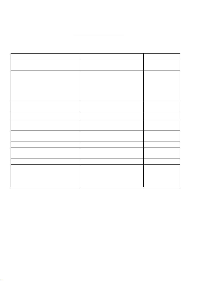
Specifications
Common Characteristics
Parameter
Value
Unit
Supported HD standards
720p
1080p, i, psF
Supported SD standards
NTSC-M / NT SC-J
NTSC-443
PAL-M
PAL-BG
SECAM
PAL-N
Display mode
Color
Picture resolution
Depends of the standard
Storage temperature
-40°C +80°C
°C
°F
Operating temperature
-20°C +55°C
°C
°F
Display type
AMLCD
Color calibration
D65 ITU-R BT.709-5
D56
Color space
Rec. ITU-R BT.709-5
Latency
Less than 1 frame in 1080 i
and PsF, SD.
Less than 1 image in 720
and 1080 p
Page 50
Page 52
Rev.0.0
CineMonitorHD3DView evolution
Jan 4th 2010
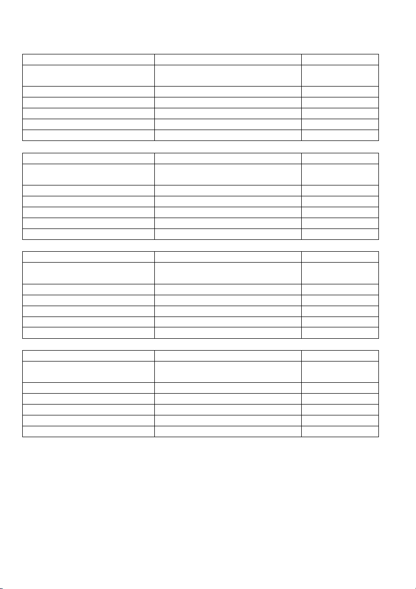
Specific - CineMonitorHD3DView6 / HD6 SBL
Parameter
Value
Unit
Dimensions
d58 x w195 x h160
d2.30 x w7.70 x h6.30
Centimeter
Inches
Weight
1250 / 2.8
Gram / Lb
Power
10– 36 / 14.5 (15.5 SBL)
Volts DC/watts
Brightness
350, SBL 1000
NIT
Contrast ratio
500 : 1 (600:1 SBL)
Sight angle
±70 H +70-60V (±80 +60-80 SBL)
°
Specific - CineMonitorHD3DView8
Parameter
Value
Unit
Dimensions
d62 x w215 x h183
d2.44 x w8.46 x h7.20
Centimeter
Inches
Weight
1680 / 3.7
Grams / Lbs
Power
10 – 36 / 17.5
Volts DC/watts
Brightness
450
NITs
Contrast ratio
500 : 1
Sight angle
±85 H&V
°
Specific – CineMonitorHD3DView12 SB
Parameter
Value
Unit
Dimensions
d68 x w298 x h285
d2.67 x w11.7 x h11.2
Centimeter
Inches
Weight
3700 / 8.1
Grams / Lbs
Power
11 – 36 / 32
Volts DC/watts
Brightness
1000
NITs
Contrast ratio
500 : 1
Sight angle
±85 H, +70-80V
°
Specific – CineMonitorHD3DView15
Parameter
Value
Unit
Dimensions
D68 x w344 x h303
d2.67 x w13.54 x h11.92
Centimeter
Inches
Weight
4850 / 10.6
Grams / Lbs
Power
10– 36 / 50
Volts DC/watts
Brightness
1200 in 2D mode
NITs
Contrast ratio
500 : 1
Sight angle
±85 H, +70-80V
°
Page 51

Page 53
Rev.0.0
CineMonitorHD3DView evolution
Jan 4th 2010
Connectors
TRANSVIDEO manufactures high quality cable assemblies and custom cables.
We encourage you to use original cables.
TRANSVIDEO cannot be liable for use of defective cables.
Accessory connector
1 GND
2 10 to 36 IN/OUT
3 Y/CVBS2/G
4 GND VIDEO
5 Pr/R
6 Pb/B
7 Run
8 GND Run
Mating plug:
LEMO8
FGG1B308CLAD62
GPI CONNECTOR J0002
Sets the function attached to each remote input on J002.
The default setup is:
J002/1 TALLY (tally active when the contact is established)
J002/2 ZOOM (change of state with a temporary contact)
J002/3 INPUT SELECT (change of input with a temporary contact)
J002/4 HORIZON “0” LEVEL (calibrate with a temporary contact)
J002/6,7,8,9 GND for pins 1,2,3,4
Page 52

Rev. 0.0
Jan 4th 2010
Doc ref:
TRANSVIDEO S.A.
Zone Industrielle
F-27135 Verneuil sur Avre
Tel +33 2 3232 2761
Fax +33 2 32 601479
Email [email protected]
http://transvideo.fr
http://transvideointl.com
 Loading...