

Page 1

Superkey Series Electronic Telephone Systems
Features and Services Description
Page 2

Table of Contents
Superkey Series
Electronic Hybrid Telephone System
SK-824 & SK-200
Features and Services Description
Table Of Contents
Advisory Messages...............................................................................................................................................5
Answer Supervision..............................................................................................................................................6
Attendant Overflow...............................................................................................................................................7
Auto Answer..........................................................................................................................................................9
Auto Call Park ....................................................................................................................................................10
Auto Hold............................................................................................................................................................11
Automatic Line Search.......................................................................................................................................12
Automatic Last Number Redial..........................................................................................................................13
Automatic Volume Increase...............................................................................................................................14
Automatic Wake Up ...........................................................................................................................................15
Background Music..............................................................................................................................................18
Behind PABX Operation.....................................................................................................................................19
Busy Remind Tone Interval................................................................................................................................20
Busy Out CO Line...............................................................................................................................................21
Call Duration Limit..............................................................................................................................................22
Call Duration Timer ............................................................................................................................................23
Call Forwarding ..................................................................................................................................................24
Call Park .............................................................................................................................................................26
Call Pickup..........................................................................................................................................................27
Call Split..............................................................................................................................................................29
Call Swap............................................................................................................................................................30
Call Transfer .......................................................................................................................................................31
Calling Proof.......................................................................................................................................................33
Camp On ............................................................................................................................................................34
Chain Dialing ......................................................................................................................................................35
Class of Service..................................................................................................................................................36
CO Break Disconnect Timer..............................................................................................................................37
CO Line Hunting.................................................................................................................................................38
CO Line Programming.......................................................................................................................................40
CO Line Ringing Types ......................................................................................................................................42
Conference.........................................................................................................................................................43
Console...............................................................................................................................................................44
Console Assignment ..........................................................................................................................................45
Conversation Monitor .........................................................................................................................................46
Date and Time Setting........................................................................................................................................47
Day Service.........................................................................................................................................................48
Dial By Name......................................................................................................................................................50
Dial 87 Group .....................................................................................................................................................53
Dial 9 Group .......................................................................................................................................................54
Dial Pulse to DTMF Conversion ........................................................................................................................55
Page ii Issue 2.3 January 2002
Page 3

Superkey ® Features and Services Description
Dial Tone Detector..............................................................................................................................................56
Direct In Line.......................................................................................................................................................57
Direct Inward System Access (DISA) ................................................................................................................58
Direct Station Selection (DSS)...........................................................................................................................62
DISA Queue Immediate Answer........................................................................................................................64
DISA Single Digit Dialing....................................................................................................................................65
DISA Special Function Access...........................................................................................................................66
Distinctive Ringing ..............................................................................................................................................67
Do Not Disturb....................................................................................................................................................68
Do Not Disturb Override.....................................................................................................................................69
Door Phone Interface.........................................................................................................................................70
Door Phone ........................................................................................................................................................71
Door Phone Controlled Switch ..........................................................................................................................72
DSS Access to Other CO Lines.........................................................................................................................73
DSS Console......................................................................................................................................................75
DTMF Signaling..................................................................................................................................................76
Dual Port Capability............................................................................................................................................77
Environment Monitor..........................................................................................................................................78
Executive Override (Barge-In.............................................................................................................................79
External Call Forwarding....................................................................................................................................80
External Music Source Interface........................................................................................................................82
External Paging Interface...................................................................................................................................83
Fax Monitor.........................................................................................................................................................84
Feature Selection from Menu............................................................................................................................85
Flash To CO Line................................................................................................................................................87
Flexible CO Line Ring Assignment ....................................................................................................................88
Flexible DSS Key Group Assignment ................................................................................................................89
Flexible Key Group Assignment.........................................................................................................................91
Flexible Ringing Assignment..............................................................................................................................93
Forced Account Code ........................................................................................................................................94
Group Assignment..............................................................................................................................................95
Hands Free Answer back...................................................................................................................................96
Hold (Exclusive)..................................................................................................................................................97
Hold (System).....................................................................................................................................................98
Hot Line.............................................................................................................................................................100
Hunt Groups .....................................................................................................................................................101
Intercom............................................................................................................................................................102
Intercom Dialing Restriction.............................................................................................................................103
Intercom Step Call............................................................................................................................................104
Last Number Redial .........................................................................................................................................105
Line Group Assignment....................................................................................................................................106
Loop Keys.........................................................................................................................................................107
Loud Bell...........................................................................................................................................................108
Macro Keys.......................................................................................................................................................109
Manual Line ......................................................................................................................................................110
Message Waiting ..............................................................................................................................................111
Meter Pulses.....................................................................................................................................................113
Monitor..............................................................................................................................................................114
Music on Hold...................................................................................................................................................115
Music Source Selection....................................................................................................................................116
Mute ..................................................................................................................................................................117
Night Service.....................................................................................................................................................118
Numbering Plan ...............................................................................................................................................120
Off Hook Ringing..............................................................................................................................................121
Off Hook Voice Announce................................................................................................................................122
On Hook Dialing ...............................................................................................................................................123
Operator Code..................................................................................................................................................124
Override ............................................................................................................................................................125
Paging...............................................................................................................................................................126
Page iii
Page 4

Table of Contents
Paging, Meet Me...............................................................................................................................................127
Passwords ........................................................................................................................................................128
Pause................................................................................................................................................................129
Pick Up Groups ................................................................................................................................................130
Port Specifications............................................................................................................................................131
Power Up Volume Adjust.................................................................................................................................133
Prime Line Select .............................................................................................................................................134
Privacy Release................................................................................................................................................135
Relay Assignment.............................................................................................................................................136
Reset Data........................................................................................................................................................137
Ring On / Ring Off Timers................................................................................................................................138
Ringing Line Immediate Connect ....................................................................................................................139
Room Monitor...................................................................................................................................................140
Saved Number Redial......................................................................................................................................141
Sensors.............................................................................................................................................................143
Silent Monitor....................................................................................................................................................145
Single Digit Dialing ...........................................................................................................................................146
Single Line Telephone Support........................................................................................................................147
Speed Dial (Personal)......................................................................................................................................149
Speed Dial (System) ........................................................................................................................................151
Speed Dial (Unrestricted).................................................................................................................................153
Station Lock ......................................................................................................................................................154
Station Message Detail Recording...................................................................................................................156
Station Number Digit Length............................................................................................................................158
Station Security Code.......................................................................................................................................159
System Programming Access..........................................................................................................................160
System Reminder.............................................................................................................................................161
Tenant Service..................................................................................................................................................163
Time of Day Display.........................................................................................................................................164
Timed Reminder - Station ................................................................................................................................165
Toll Control .......................................................................................................................................................166
Transfer Recall Timeout...................................................................................................................................167
Traveling Class of Service ...............................................................................................................................168
Trunk Queue (Trunk Callback)........................................................................................................................169
Uniform Call Distribution..................................................................................................................................170
Unsupervised Conference ...............................................................................................................................172
Voice Mail Interface ..........................................................................................................................................173
Voice Service Unit.............................................................................................................................................176
Appendix A- DISA Detailed Description...........................................................................................................177
DISA Overview..................................................................................................................................................177
DISA Call Flow Charts......................................................................................................................................182
DISA With No Voice Service Unit - Chart 1 ....................................................................................................183
DISA With No Voice Service Unit - Chart 2 .....................................................................................................184
DISA With No Voice Service Unit - Chart 3 .....................................................................................................185
DISA With a Voice Service Unit Chart 1 ..........................................................................................................186
DISA With a Voice Service Unit - Chart 2........................................................................................................187
DISA With a Voice Service Unit - Chart 3Chart 3Chart 3................................................................................188
Appendix B - Toll Control Detailed Description ...............................................................................................189
Index To Programming Forms .........................................................................................................................193
Page iv Issue 2.3 January 2002
Page 5

Superkey ® Features and Services Description
Advisory Messages
Description
Up to ten system advisory messages can be used on the system. Nine messages are pre-programmed
into the system and one is blank. All messages may be modified so default messages may be changed if
desired. The nine pre-programmed messages may be edited on an individual telephone to include numeric
information as to the status of the telephone set user, such as the time or date when the user will return.
The nine pre-programmed messages are as follows:
0. On Vacation 3. In a Meeting 6. Call Stn
1. Will Be Back 4. Call 7. Gone for the Day
2. At Lunch 5. Do Not Disturb 8. Out of Town
Message #9 will appear as a blank message to anyone who accesses the message. It is possible for many
users to utilize message 9 as a custom message and each station can display its own individual message.
Conditions
Messages can be placed on any telephone set and may be read by any display telephone set.
Individual message entry is performed using the letters that appear on the telephone keypad as follows:
Key 1 = Q - Z - (Blank Space) - 1 Key 2 = A - B - C - 2
Key 3 = D - E - F - 3 Key 4 = G - H - I - 4
Key 5 = J - K - L - 5 Key 6 = M - N - O - 6
Key 7 = P - R - S - 7 Key 8 = T - U - V - 8
Key 9 = W - X - Y - 9 Key 0 = (Period) : & 0
Key # = ( ) $ # Key * = (Dash) / ! *
Redial = Backspace MSG = Forward
Programming
None
Operation
Superkey electronic telephone set:
To select and set a message
1. Press [PGM].
2. Press [MSG]. (This function may also be accessed from the features menu. For more information,
see Feature Selection from Menu, page 85 of this document).
3. Display will show:
Select Message
Enter Message #__
4. Press [VOL ↑] or enter the message number required. Display will show message number 0 in list
(if [VOL ↑] is pressed) or will display the entered message.
5. To see next higher numbered message, press [VOL ↑] to see next lower numbered message,
press [VOL ↓].
6. When desired message is found, station user can enter additional information via the keypad if
desired.
7. When the entry is satisfactory, press [SAVE]. The set will provide confirmation tone that the
message has been selected. Press [SPK]. The display will now show the active message. Any
display stations that call will receive the active message.
To remove a message
1. Press [PGM]
2. Press [MSG]
3. Press [SPK]
Page 5
Page 6

Answer Supervision
Description
The Superkey electronic telephone system is equipped to provide answer supervision in applications where
it is provided by the telephone company as a polarity reversal. When active, answer supervision provides
accurate timing information for the preparation of SMDR records within the system.
Conditions
Answer Supervision will operate only if it is being provided by the local telephone company.
Programming
Form 12-01 (Recording Start Time) should be set to [0] in order to allow the system to accurately expect
answer supervision, if available. If answer supervision is not provided by the local telephone company, this
parameter should be set to a time that is representative for a call to be placed. For more information,
please see Station Message Detail Recording, page 156 of this document.
Form 12-08 (Detect Polarity Reversal) must be set to [0], enable, in order to recognize answer supervision
by polarity reversal.
Operation
Operation of Answer Supervision is automatic.
Page 6 Issue 2.3 January 2002
Page 7
Superkey ® Features and Services Description
Attendant Overflow
Description
The Superkey electronic telephone system allws you to designate one station as a main answering position
or attendant console for incoming CO calls. If that station is busy, the system can select another station that
may act as a backup answering position. The system allows up to 15 backup positions behind each
attendant, for a possible total of 16 answering positions. There are two variations of Attendant Overflow.
Linear Ringing will search through the list of possible backup answering positions and will ring the first
available station. Free stations will be searched in the order programmed on Form 42 (or 43 if Night
Service).
Circular Ringing works like Linear Ringing except that it always begins its search immediately after the last
station that was rung.
Hunting will ring the first available station. If that station does not answer within the time parameter
specified on the system, the system will "add on" the next available station. This timer will repeat until the
call is answered, abandoned or until every programmed available station is ringing.
Automated Attendant functions may also be used as a means of Attendant Overflow. For more information,
please see Appendix A - DISA Detailed Explanation in this manual.
Conditions
The CO line must be programmed for Linear ringing if the Linear Overflow method of operation is preferred.
The CO line must be programmed for Hunt if the timed "add on" method of operation is desired.
Ringing Type is programmed on Form 46-LINE-07 for Day Service and Form 46-LINE-08 for Night Service.
Stations will be selected in the order that they are programmed on the incoming ringing assignment forms
(Form 42-[CO]-[station] and Form 43-[CO]-[station]).
Programming
Day Ringing Assignment, Form 42-[CO]-[station] must be programmed for each CO line in the system. Up
to sixteen stations may be programmed for each line on the SK-824. The SK-200 can be programmed for
up to 40 stations. Lines programmed for Linear Overflow or Hunt will search this form in the order that
stations are programmed. The system will ring the first available station in this group. This form controls
ringing assignments during day service only.
Night Ringing Assignment, Form 43-[CO]-[station] is as listed above for Form 42, but determines the
stations that will ring when the system is in Night Service.
Hunt Time Assignment, Form 01-08-01 sets the interval for adding stations to the ringing sequence in a no
answer condition if Hunt is selected. Every time a station begins ringing, this timer will begin. If it expires
without the call having been answered, the next available station in the group defined on Form 42-[CO][station] or Form 43-[CO}-[station], whichever is applicable, will be added to the ringing sequence. Valid
settings for this option are:
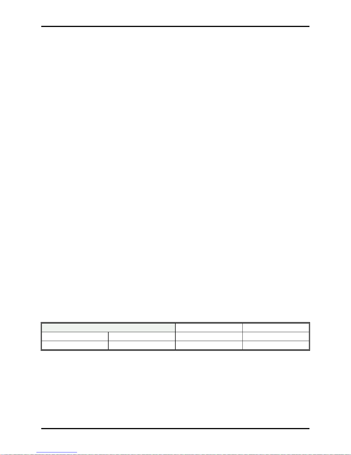
Hunt Time Assignment, Form 01-08-01 0=Disabled 1=2 seconds
2=4 seconds 3=6 seconds 4=8 seconds 5=15 seconds
6=30 seconds 7=60 seconds 8=120 seconds 9=254 seconds
Note: If Form 01-08-01 is set at 0 (disabled), CO line hunting will only occur on busy stations. The first
free station will be rung and the call will not add stations to the ringing sequence in a no-answer
condition.
Page 7
Page 8

CO Line Assignment Day Ringing Method, Form 46-[CO]-07 determines whether hunting or linear
operation will occur during day service. The options for Form 46-[CO]-07 are:
CO Line Day Ringing Method, Form 46-[CO]-07 0=Common Audible
1=LINEAR 2=Circular 3=HUNT
CO Line Assignment Night Ringing Method, Form 46-[CO]-08 determines whether hunting or linear
operation will occur during night service. The options for 46-[CO]-08 are:
CO Line Night Ringing Method, Form 46-[CO]-08 0=Common Audible
1=Linear 2=Circular 3=Hunt
Operation
Linear:
On an incoming call the first available station according to Form 42 or Form 43 will be rung.
Circular:
On an incoming call the first available station according to Form 42 or 43 and after the last location
rung will be rung. If the last entry in Form 42 or Form 43 is reached, the system will “wrap around”
and begin searching at the beginning of Form 42 or Form 43.
Hunt:
1. On an incoming call, the first available station (according to Form 42-[CO]-[station] or Form 43[CO]-[station]) will be rung.
2. If there is no answer within the time period determined by Form 01-08-01, the system will check
the applicable form (Form 42 or Form 43) and add the next programmed station to the ringing
sequence. This step will repeat until the call is answered, abandoned or all available stations on
the applicable form (Form 42 or Form 43) are ringing.
Page 8 Issue 2.3 January 2002
Page 9
Superkey ® Features and Services Description
Auto Answer
Description
Auto Answer allows a speaker phone equipped station to answer all intercom calls automatically. After Auto
Answer is activated on a station, all intercom calls will be placed on the speaker phone as soon as the
calling party dials the Auto Answer extension. The speaker phone equipped station can carry on a
conversation without touching the telephone. When the originating caller hangs up, the Auto Answer set will
revert to an idle state. Auto Answer applies only to intercom calls. Outside callers must always be
answered by the station.
Conditions
Auto Answer can only work on a Superkey electronic telephone set equipped with speaker phone.
Auto Answer capability is active whether the system is programmed for Voice Signalling or Ring Signalling.
For security purposes, CO calls will ring and must be answered manually.
Programming
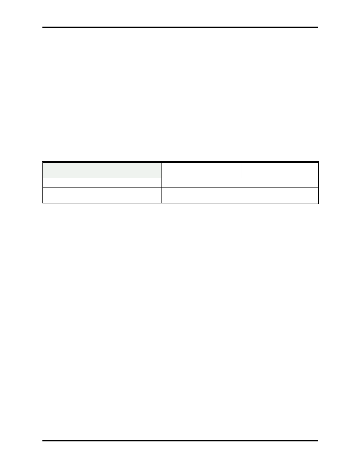
Form 27-Station-03 controls individual stations' utilization of Auto Answer. There are 6 possible settings.
Form 27-STN-03 Auto Answer Flag 0= Auto Answer Manual 1=Auto Answer On/MIC
Light Lit
2=Auto Answer On/MIC Light Off 4= Auto Answer Manual/Speakerphone MIC On
5=Auto Answer On/MIC Light Lit
Speakerphone MIC On
6=Auto Answer On/MIC Light Off
Speakerphone MIC On
Operation
Operation is as described under programming, above.
Page 9
Page 10

Auto Call Park
Description
Auto Call Park allows any user of a Superkey electronic telephone set equipped with LCD display (SKEKT/D) to place a call directly into a call park orbit without the need to search for the first available orbit
position. Unlike conventional call park, this method will search for the first available parking orbit.
Conditions
Its use is limited only to LCD electronic telephone sets. Only LCD sets have the ability to display the
information necessary to retrieve the parked call.
Auto Call Park cannot be accessed from a non-display telephone set.
Programming
The LCD set must be equipped with a Call Park button. This is programmed on Form 22 for an available
key. For more information on programming a call park button, please see Flexible Key Group Assignment,
page 91 of this document.
Operation
1. An LCD set is on a call.
2. The LCD set presses the Call [Park] Button.
3. The call is placed on Hold.
4. The upper half of the display will remain the same as before the parked call was placed in park
orbit. The lower half of the LCD display will show:
To Orbit # x
where x orbit number where the call is placed.
To retrieve a call from park, see instructions listed in Call Park, page 26 of this document.
Page 10 Issue 2.3 January 2002
Page 11

Superkey ® Features and Services Description
Auto Hold
Description
Auto Hold allows a station user to automatically place a caller on hold while performing another function.
Its most common use is in transferring a call. Any use of a programmed DSS station key while on a
conversation will automatically place the caller on hold.
Conditions
This feature is only available from Superkey electronic telephone sets.
Note: System function is the same as if the station user pressed the [HOLD] key prior to pressing a DSS
key.
Programming
None
Operation
1. Station user is involved in a conversation.
2. Station user presses any programmed DSS key.
3. Conversing party is automatically placed on hold.
Page 11
Page 12
Automatic Line Search
Description
Automatic Line Search, Form 01-03-02 permits Speed Dial, Last Number Redial and Saved Number Redial
to search for an available CO line. If this function is enabled, Speed Dial Numbers need not have a CO line
number specified for an outgoing call. If an outgoing line is specified and that line is busy, the Superkey
electronic telephone system will search the originating station's Dial 9 Group for an available outgoing line
and seize it to place the call.
If Last Number Redial or Saved Number Redial is used, the system will attempt to access the CO line on
which the call was originally placed. If Auto Line Search is enabled and the original line is busy, the system
will search for another line in the outgoing group.
If Automatic Line Search is disabled, Speed Dial, Last Number Redial and Saved Number Redial will only
access the line originally designated. If it is busy, the function will be disallowed.
Conditions
If System Speed Dial does not specify a CO line, it will access the individual user’s Dial 9 Group. This
parameter has no effect on such System Speed Dial calls.
Programming
Form 01-03-02, Automatic Line Search must be enabled to allow line searching. Valid parameters are
listed below:
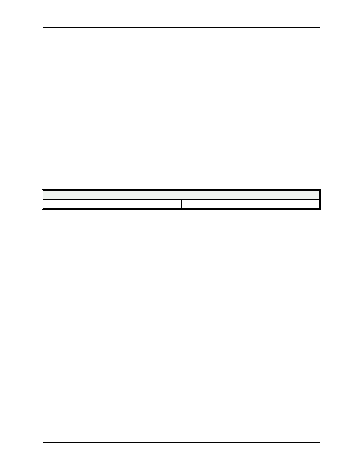
Automatic Line Search, Form 01-03-02
0=Auto Search Enabled 1=Auto Search Disabled
Operation
Operation is automatic.
Page 12 Issue 2.3 January 2002
Page 13
Superkey ® Features and Services Description
Automatic Last Number Redial
Description
Automatic Last Number Redial permits a station user to periodically redial the last number dialed. It utilizes
the Last Number that was dialed from the telephone, like Last Number Redial, but it will repeatedly attempt
to dial the number, like Saved Number Redial. Once invoked, it will automatically call the Last Number
Dialed a pre-determined number of times. See also, Saved Number Redial, page 141 of this document.
Conditions
Automatic Last Number Redial is not available to Single Line Telephone sets.
A station must have a [SPD] dial key and a [Redial] key in order to access this function.
This function will not work on telephones with Form 27-STN-03 programmed with parameters 4, 5 or 6.
Programming
Form 01-02-03, Auto Redial Wait for Answer Time determines the amount of time the telephone will remain
off hook, waiting for an answer. Please note that if the called telephone number answers during this time
period, the call will still be abandoned if no action is taken by the station user. The valid parameters for this
options are listed below:
Note: The timer starts upon line seizure, before digits are outpulsed. If Pulse signalling is used, 01-02-03
must contain a value that allows for the slower pulse dialing. For example, if pulse dialing requires
7 seconds and Wait for Answer is set for 10 seconds, less than 3 seconds will remain for the call to
ring and be answered. In all likelihood the call will never be completed.
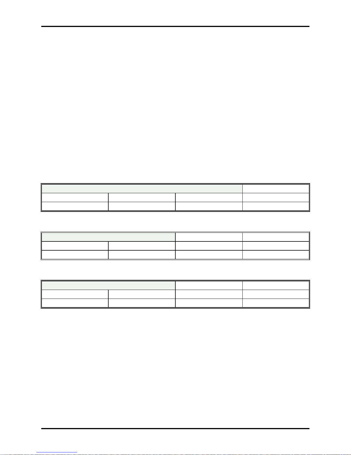
Auto Redial Wait for Answer Timer Form 01-02-03 1=10 seconds
2=20 seconds 3=30 seconds 4=40 seconds 5=50 seconds
6=60 seconds 7=70 seconds 8=80 seconds 9=90 seconds
Form 01-05-07, Auto Redial Attempts controls the amount of times that Saved Number Redial will Auto dial
a Saved Number before abandoning any further attempts. Valid settings are listed below:
Auto Redial Attempts Form 01-05-07 0=No Attempts 1=10 Attempts
2=20 Attempts 3=30 Attempts 4=40 Attempts 5=50 Attempts
6=60 Attempts 7=70 Attempts 8=80 Attempts 9=90 Attempts
Form 01-05-08, Auto Redial On Hook Timer programs the idle interval between call attempts. The valid
options for this parameter are listed below:
Auto Dial On Hook Timer Form 01-05-08 0=10 seconds 1=20 seconds
2=30 seconds 3=40 seconds 4=50 seconds 5=60 seconds
6=70 seconds 7=80 seconds 8=90 seconds 9=100 seconds
Operation
1. Make an outgoing telephone call.
2. Hang Up.
3. Press [SPD]. Press [Redial]
4. The telephone system will automatically seize an outgoing CO line and redial the number that was
dialed in step 1 above.
The Auto Redial portion of the function is canceled if any station user action is taken. Pressing the [MIC]
button or lifting the handset while a call is in progress will cancel the off hook timer and the call will remain
in place. Pressing the [SPK] button while the call is in progress will abort the Auto Redial function. Placing
another call during the On Hook timer (while the telephone is idle) will not abort the Auto Redial function. It
will resume after you have returned the telephone to idle.
Page 13
Page 14

Automatic Volume Increase
Description
Automatic Volume Increase is an option that is available through Class of Service programming. It is
independently assigned per station.
Automatic Volume Increase will cause the volume of a ringing station to increase as the call continues to
ring. The ringing volume will increase approximately every two ring cycles.
Conditions
This options applies only to Superkey electronic telephone sets.
Programming
Form 26-[station]-03, activates or deactivates this option. Valid settings are:
Automatic Volume Increase, Form 26-[station]-03 0=Disable 1=Enable
Selection of Automatic Volume Increase is also programmable from from each electronic telephone set.
1. Press [PGM].
2. Press 6.
3. Press 4. LCD sets will display Volume Up Gradually ->
4. Press [PGM]. Automatic Volume Increase will be active on the set.
To remove this option, the same procedure as above should be followed, except that the LCD will display >CANCEL on step 3.
Operation
Operation is automatic.
Page 14 Issue 2.3 January 2002
Page 15
Superkey ® Features and Services Description
Automatic Wake Up
Description
Superkey electronic telephone systems are equipped with the ability to provide Automatic Wake Up Call
service to stations within the system. Using Automatic Wake up service, a station can be made to ring at a
pre-programmed time. When the station answers, the system will either connect them to the background
music source, or to the Voice Service Unit channel dedicated to Wake Up service.
Conditions
Only one wake up call can be programmed on a telephone at a time.
Wake up calls are removed from the system when the station answers.
A Superkey electronic telephone set without LCD display must have a [REMIND] button programmed in
order to program a Wake Up call.
LCD equipped Superkey electronic telephone sets may also access this feature via the Feature Selection
from Menu capability. See Feature Selection from Menu, page 85 of this document.
Programming
Form 01-05-01, Automatic Wake Up Call Signalling determines the audio used on Automatic Wake Up
Calls. Valid selections are:
Automatic Wake Up Signaling, (01-05-01) 0=VSU Channel 1=Background Music
Voice Service Unit Assignment, Form 14 must have one of its eight possible channels programmed as type
14, Automatic Wake up service in order to provide a recorded wake up message. See also, Voice Service
Unit on page 176 of this document.
Operation
To set a Wake Up call from a Superkey station:
1. Press [PGM].
2. Press [REMIND]. (This function may also be accessed from the features menu. For more
information, see Feature Selection from Menu, page 85 of this document).
3. Enter the wake up time in 24 hour format (00:00 - 23:59).
4. Enter the duration as 99 (indicates a self cancelling alarm).
5. Press [SAVE].
6. Press [SPK] to exit.
To set a Wake Up call from a Superkey station defined as a console on Form 04, (see Console
Assignment, page 45 of this document):
1. Press [REMIND].
2. Display will show:
SYS REMINDER *
OR DIAL STN#
3. Enter the station number.
4. The Display will show:
XXXX hh:mm dd
CHANGE? 1=Y 2=N
Where:
XXXX=the station number entered.
hh=hour mm=minutes dd=duration/type
If no wake up is presently set, the final two digits of the time and duration section will show 00. The
time may show a previously programmed wake up or reminder time.
Page 15
Page 16
If a wake up is presently set, the time of the wake up will be shown and the duration will be
displayed as 99. If duration is set at anything other than 99, a repeating Timed Reminder is active
on the set.
5. Enter [1] to enter or change the wake up time or [2] will exit the Wake Up Program and return the
set to idle operation.
6. The display will show:
ENTER TIME __:__
ENTER TYPE __
7. Enter the wake up TIME in 24 hour format (00:00 - 23:59).
8. Enter the TYPE as 99 (indicates a self cancelling alarm).
9. Press [SAVE].
10. Display will show:
Reminder Set !!
XXXX hh:mm 99
The entry confirms the wake up call was accepted.
11. Press [SPK].
To cancel a Wake Up call from a Superkey station:
1. Press [PGM].
2. Press [REMIND].(This function may also be accessed from the features menu. For more
information, see Feature Selection from Menu, page 85 of this document).
3. Enter 00 00 00
4. Press [SAVE].
5. Press [SPK] to exit.
To cancel a Wake Up call from a Superkey station defined as a console on Form 04, (see Console
Assignment, page 45 of this document):
1. Press [REMIND].
2. Display will show:
SYS REMINDER *
OR DIAL STN#
3. Enter the station number.
4. The Display will show:
XXXX hh:mm dd
CHANGE? 1=Y 2=N
Where:
XXXX=the station number entered.
hh=hour mm=minutes dd=duration/type
5. Enter [1] to enter or change the wake up time or [2] will exit the Wake Up Program and return the
set to idle operation.
6. The display will show:
ENTER TIME __:__
ENTER TYPE __
7. Enter 00 00 00
8. Press [SAVE].
9. Display will show:
Reminder Set !!
XXXX 00:00 00
This information will confirm cancellation of the wake up call.
Page 16 Issue 2.3 January 2002
Page 17

Superkey ® Features and Services Description
10. Press [SPK].
Note: LCD equipped stations may activate or cancel the Wake Up features listed above (for console and
individual user) through the use of Feature Selection from Menu. See page 85 of this document.
To program a Wake-Up call from a single line station:
1. Lift Handset.
2. Dial [7],[0],[0],[1].
3. Dial the Time that you wish the wake up call to notify you (24 hour format 00:00-23:59). Must be
four digits.
4. Enter [9],[9], to indicate a Wake-Up call.
5. Hang up. The wake-up call is set.
To cancel a Wake-Up call before it rings from a single line station:
1. Lift Handset.
2. Dial [7],[0],[0],[1].
3. Dial [0],[0],[0],[0],[0],[0].
4. Hang up. The wake-up call is canceled
Automatic Wake Up calls will automatically cancel when the call is answered. The method listed above is
only required when you wish to cancel the call before it is activated.
At the Programmed Wake Up Call time, the station will ring. Upon answer, the station will be connected to
either the Voice Service Unit channel programmed or to the system background music source.
If a Wake Up call is not answered, the system will ring the telephone for a period of one minute. If the call
is not answered after one minute of ringing, the system will re-ring the station in three minutes. This will
continue until the call is answered. If an operator station is programmed with a Wake Up key, an
unanswered Wake Up at any station will cause the Wake Up key to flash. If the Wake Up button is pressed
while it is flashing, the display will show the following:
xx NAME
No Wake Up hh:mm
The operator can press [SPK] or lift the handset to immediately recall the station. If the operator lifts the
handset or presses [SPK], the Wake Up is automatically canceled.
Page 17
Page 18
Background Music
Description
Background Music allows Superkey electronic telephone set users to listen to either the internal music
synthesizer or an external music source (External #2) over the built in speaker. This music source may be
shared with the Music-On-Hold Source or it may be programmed and connected independently.
Conditions
The telephone set must be a Superkey electronic telephone.
Background music will be deactivated when the speaker phone is accessed or when the station goes off
hook or an incoming call rings the station.
If background music is activated, it will return to operation when the telephone becomes idle again.
Programming
SK-824 Form 01-08-08, Music Source Selection is used to select the music source.
The choices allow the use of the internal system music synthesizer or External Music Source #2.
01-08-08 Background Music Source Music On Hold Source
0 Internal Source Internal Source
1 External Source #2 Internal Source
2 Internal Source External Source #1
3 External Source #2 External Source #1
4 Internal Source External Source #2
5 External Source #2 External Source #2
SK-200 Selection of Music On Hold Sources and Background Music Sources is via jumpers on the SKCPU/2 card in cabinet #1 of the SK-200. Please see the SK-200 Installation and Maintenance Manual for
more information.
Operation
While the telephone is in an idle state, press the [#] key on the keypad. Background music (if present on
the system) will be heard. The [SPK] key will illuminate.
To remove background music from a telephone set, press [#]. The [SPK] key will extinguish and
Background Music will cease.
Page 18 Issue 2.3 January 2002
Page 19
Superkey ® Features and Services Description
Behind PABX Operation
Description
Superkey electronic telephone systems can operate as "Behind PABX" or Centrex Operation. In this mode,
the system makes allowances for connection to other than a normal Central Office Line. The primary
differences have to do with the operation of Station Message Detail Recording (SMDR) and Toll Control.
See Station Message Detail Recording, page 156 of this document and Toll Control, page 166 of this
document.
Conditions
Lines programmed as PABX lines will be treated differently for purposes of Toll Control. If, when on a line
programmed as PABX, the digit programmed in Form 01-03-04 is not dialed as the first digit, an inside
PABX call is assumed and no Toll Restriction is applied.
Programming
PABX (Centrex) Outgoing Code, Form 01-03-04 must be programmed to correspond to the access code
used to access a CO line on the PABX., i.e., if [9] is used to access a CO line on the PABX, [9] should be
programmed as the PABX (Centrex) Outgoing Code on Form 01-03-04. The valid parameters are listed
below:
PABX Outgoing Code, (Form 01-03-04 ) 0=0 1=1
2=2 3=3 4=4 5=5 6=6 7=7 8=8 9=9
CO Line Type, Form 46-[CO]-01 must be set for PABX operation for the system to recognize operation
behind PABX. Valid parameters are:
CO Line Type, (Form 46-[CO]-01) 0=CO Line 1=PABX Line
Note: It is not necessary to program lines as PABX for them to operate behind PABX systems. Behind
PABX operation is a convenience that provides the ability to continue to effectively track Toll Control
without the need to assess the impact of a PABX access code.
Should an installation occur where there is no need for Toll Control, it may be easier for installation
personnel to ignore the behind PABX programming of the system.
Operation
Behind PABX Operation is fully automatic.
Page 19
Page 20

Busy Remind Tone Interval
Description
Busy Remind Tone Interval determines the timing interval for muted ring signals when a call is camped-on
to a busy station. See also Camp-On, page 34 of this document.
Conditions
None.
Programming
Busy Remind Tone Interval is programmed on Form 01-01-05. Valid parameters for busy remind tone are
listed below:
Busy Remind Tone Interval (Form 01-01-05) 0=Disabled 1=2 seconds
2=4 seconds 3=6 seconds 4=8 seconds 5=15 seconds
6=30 seconds 7=60 seconds 8=120 seconds 9=254 seconds
Operation
See Camp-On, page 34 of this document.
Page 20 Issue 2.3 January 2002
Page 21
Superkey ® Features and Services Description
Busy Out CO Line
Description
Form 41-[CO] allows a system administrator or service personnel to remove a CO line from service. This
allows service personnel or system administrator to take a non-functioning line out of operation with the
least possible disruption of service. Normally the CO line when busied out will illuminate the LED on any
line key appearances, but the ability also exists to remove the line without illuminating the LED. Also, it is
possible to busy out a CO line for outgoing calls, but keep them available for incoming calls.
Conditions
Anyone wishing to busy out a line must have access to system programming.
Programming
A station must have access to system programming in order to Busy Out or Return a CO line to service.
1. Press [PGM]. Press [2].
2. Enter Password (if programmed).
3. Press [SAVE].
4. Enter [4][1]. (Access form 41, BUSY OUT CO LINE).
5. Enter the CO line that you wish to affect (Two digits, 01 - 08).
6. Press [SAVE].
7. Enter the appropriate code. Codes and results are listed below:
0=Normal Operation 1=Busy Out Outgoing - No LED
2=Busy Out Both way - No LED 3=Busy Out Both way - LED lit (red).
8. Press [SAVE]. Press DSS Key #5.
Operation
When a CO line is busied out, any attempts to access the line will result in a busy tone, as if the line was in
use. LCD telephone sets will see "Restricted" in the telephone display when access is attempted.
Page 21
Page 22

Call Duration Limit
Description
This feature allows The Superkey electronic telephone system to limit the length of telephone calls. This
feature is programmable on a per station basis. A station with Call Duration Limit programmed will hear a
warning tone 10 seconds prior to duration expiration. The action taken by the system will be determined by
the type of duration limit action that has been programmed.
Conditions
1. The call duration timer is programmable on a per station basis and is programmable in one minute
increments from 1 minute to 9 minutes [1-9] (Form 24-[station]-03). It may also be disabled so that
there is no time limit on call by entering [0] in Form 24-[station]-03.
2. The timer is invoked per station.
Programming
Form 01-04-03, Call Duration Limit Type determines the type of limiting notification given.
A setting of 0 or 5 provides a continuous busy tone to the limited station at the timeout period A
communications path still remains between the internal station and the outside CO line. The CO line does
not hear the tone.
A setting of 1 or 6 (Form 01-04-03) provides a 1 second warning tone at each duration limit interval. The
call is left intact at all times.
A setting of 2 or 7 (Form 01-04-03) provides a 1 second warning tone 10 seconds prior to duration limit
timeout. At 5 seconds before timeout, continuous busy tone is provided to the internal station. The CO line
does not hear tone. At timeout, the call is disconnected.
Settings of 0, 1 and 2 apply only to outgoing calls. Settings of 5, 6 and 7 apply to incoming and outgoing
calls.
Form 24-[station]-03, Call Limit Duration determines the allowed timeout period. If set to 0, Call Duration
Limit is disabled. If set to 1-9, call duration limit is from 1 to 9 minutes, corresponding to the entry setting.
Operation
If a station is subject to the Call Duration Limit, when the allotted time (as per Form 24-[station]-03) has
expired, the action taken will be determined by the value set in Form 01-04-03 (Call Duration Limit Type).
Page 22 Issue 2.3 January 2002
Page 23

Superkey ® Features and Services Description
Call Duration Timer
Description
Call duration timer is an automatic function that is available to all telephone set users equipped with
Superkey LCD electronic telephone sets. All outgoing calls are automatically timed as soon as the trunk is
accessed for an outgoing call. The telephone set will display the actual time since connection. The timer
continues to operate even if the call is held or transferred. In the case of a transfer, the destination party's
telephone set will show the total call time, not the time since transfer.
Conditions
None
Programming
None
Operation
Automatic
Page 23
Page 24
Call Forwarding
Description
This feature allows a station user to have all calls which are directed to his station forwarded to a selected
station number within the Superkey electronic telephone system.
Conditions
There are four types of call forwarding:
1. Call Forwarding "All Calls" (ALWAYS).
2. Call Forwarding "BUSY."
3. Call Forwarding "NO ANSWER."
4. Call Forwarding "BUSY/NO ANSWER."
Programming
System Programming:
Form 01-01-08, Call Forward No Answer Timer determines the time the system will allow before forwarding
an unanswered call. This location will accept an entry from 0 to 9. The settings and the corresponding
timers are listed below:
Call Forward No Answer Time (01-01-08) 0=10 seconds 1=20 seconds
2=30 seconds 3=40 seconds 4=50 seconds 5=60 seconds
6=70 seconds 7=80 seconds 8=90 seconds 9=100 seconds
See Also, Flexible Key Group Assignment, page 91 of this document.
For Superkey electronic telephone sets:
1. Press [PGM]
2. Press [CFWD] (if programmed on set) or [1] if there is no CFWD button on the set. (This function
may also be accessed from the features menu. For more information, see Feature Selection from
Menu, page 85 of this document).
3. If telephone set is equipped with LCD display, display will show:
FWD 1=ALL 2=BUSY
3=NO/A 4=BSY/NOA
4. Station User dials 1-4 depending on type of forwarding desired. If equipped with LCD display, it will
show:
ENTER EXTENSION
OR PRESS DSS _____
5. Press the DSS key of the forwarding destination or dial the station number of the forwarding
destination (Forward to___).
6. If CFWD button is programmed, CFWD button will light and blink.
7. Display will show:
YYYY -> XXXX
Tue. Aug.06 01:06
YYYY= Your Extension Number
XXXX=Forwarding Destination
Lower portion of display will show current date and time.
This indicates that call forwarding is programmed and active on the telephone. If the telephone is
programmed with a [CFWD] key, the key will flash at 60 impulses per minute.
To cancel call forwarding from a Superkey electronic telephone set:
Page 24 Issue 2.3 January 2002
Page 25
Superkey ® Features and Services Description
1. Press [PGM]
2. Press [1]. (This function may also be accessed from the features menu. For more information,
see Feature Selection from Menu, page 85 of this document).
3. Display will show:
FWD 1=ALL 2=BUSY
3=NO/A 4=BSY/NOA
4. Enter the type of call forwarding that is active.
5. Display will show:
ENTER EXTENSION
OR PRESS DSS _____
6. Enter your station number (the station cancelling the forwarding). Call Forwarding is now
cancelled.
If telephone set is equipped with CFWD button:
Press [CFWD]. [CFWD] light will extinguish.
Note: A station with a [CFWD] button programmed does not need to program call forwarding for each
activation. The [CFWD] button will invoke the last forwarding programmed into a telephone set.
Once Call Forwarding is programmed on a set, it may be activated and de-activated by pressing
the [CFWD] button. It only becomes necessary to re-program when the type of forwarding or the
forwarding destination is to be changed.
Note: Call Forwarding may also be programmed through access via the Feature Selection Menu. For
information on the Feature Selection Menu, see Feature Selection from Menu, page 85 of this
document.
To set Call Forwarding on Single Line Telephones:
1. Lift the handset.
2. Press [7],[0],[1],[1] for All Calls
OR
Press [7],[0],[1],[2] for Busy
OR
Press [7],[0],[1],[3] for No Answer
OR
Press [7],[0],[1],[4] for Busy/No Answer.
3. Dial the forwarding destination station. You will hear a confirmation tone.
4. Hang up.
To cancel Call Forwarding from a Single Line Telephone Set
1. Lift the handset.
2. Press [7],[0],[1],[1]
3. Dial your own station number.
4. Hang Up.
Operation
Calls will be forwarded under the conditions selected above.
Page 25
Page 26

Call Park
Description
Call Park allows station users to "mark" calls for easy retrieval. Retrieval is usually by other stations as a
result of a page. It's primary uses are in conjunction with single line telephones that have to place more
than one call on hold at a time and environments where paging is used extensively to route calls. Call Park
places an outside caller on Hold into a specific numeric assignment. The call can then be picked up by any
other station by dialing the same numeric location code.
See also Auto Call Park, page 10 of this document.
Conditions
Parking applies only to outside calls.
Programming
None.
Operation
To Place a Call in a Call Park Orbit:
From a Superkey electronic telephone set:
1. Place the outside caller on Hold.
2. Dial 85, plus the park location (0-9) where you wish to store the call. If the selected location is in
use, you will hear busy tone. If the telephone is equipped with LCD display, the display will show:
Park Orbit Busy
Try Again!
Otherwise the call will be stored in the park orbit requested.
From a single line telephone:
1. Place the outside caller on Hold by pressing the Hook switch †.
2. Dial, 85 plus the park location (0-9) where you wish to store the call. If the selected location is in
use, you will hear busy tone. You may immediately dial another park number (0-9) to store the call.
When the system has accepted the call into an orbit location, you will hear continuous dial tone.
To retrieve a call from a park location:
1. Lift handset or press SPKR.
2. Dial 85, plus the location where the call is parked.
3. You will be connected to the caller. If you attempt to retrieve a call from a location where no call is
stored, you will hear busy tone.
† In some systems Call Hold may require the digit 7 to be dialed after a hook switch flash. This is
dependant upon system programming. If in doubt, consult your system manager.
Page 26 Issue 2.3 January 2002
Page 27
Superkey ® Features and Services Description
Call Pickup
Description
Call Pickup allows a station user to answer a call ringing (or voice announce) at another station. The
system allows these assignments to be set up independently for day service and night service.
Conditions
There are five different types of pickup that can be accomplished. They are:
1. CO Line
2. Station Group
3. Stations
4. Department (Your own group)
5. DSS Pushbutton Pickup
Note: DSS Pickup cannot retrieve calls from telephones that are in Call Forwarding mode.
Programming
Control of individual trunks is through Form 46-[CO]-05. Settings are as follows:
Setting Day Service Night Service
0 Disabled Disabled
1 Disabled Enabled
2 Enabled Disabled
3 Enabled Enabled
Form 28-[station]-01, Station Group Assignment determines the group that can be picked up by the station
group option.
See Also, Flexible Key Group Assignment, page 91 of this document.
Operation
From Superkey electronic telephone sets:
1. Lift Handset or press [SPK] key.
2. Press [PICKUP] key or [*] key on keypad.
3. If the telephone is equipped with LCD, the display will show:
1=LN 2=GP
3-STN 4=DEPT.
4. User presses:
[1] Line number for desired CO line
[2] to select a ringing group
[3] to select a specific station.
[4] to answer a ringing set within your own group.
[*] to retrieve the oldest call, regardless of its type.
If [1] is selected, enter the CO line number to be picked up (1-8 on SK-824, 01-40 on SK-200).
If [2] is selected, enter the group number to pick up.
If [3] is selected, enter the station number to pick up.
If [4] is selected, station user will be connected to the first ringing telephone within that station's own group.
If [*] is selected, the call that has been ringing the longest in the system will be answered, regardless of its
status as an outside call, an intercom call, or a hold recall.
Page 27
Page 28

DSS Pushbutton Pickup:
1. Lift Handset.
2. Press the flashing DSS button of a ringing station.
3. You will be connected to the caller.
Note: DSS Pickup cannot retrieve calls from telephones that are in Call Forwarding mode.
Page 28 Issue 2.3 January 2002
Page 29

Superkey ® Features and Services Description
Call Split
Description
Call Split is a feature that allows a Superkey electronic telephone set user to "split" a conference into two
separate conversations. This feature is advantageous when it becomes necessary to converse privately
with one of the parties in the conference.
Conditions
A conference must be established containing yourself and two other parties.
Conferencing must be enabled on your station.
Programming
It is necessary to program a DSS key as a [SPLIT/SWAP] key. This is available on Form 22, Flexible Key
Group Assignment. For programming information regarding Form 22, please see page 91 of this
document.
Form 26-STN-04 Conference, determines if a station has the ability to conference. A setting of 0 (enable) is
default. To disable conferencing, set Form 26-STN-04 to 1 (disable).
Operation
While in a conference:
1. Press [SPLIT/SWAP].
Note: After the conference is split, it is possible to alternate between parties by pressing [SPD], [#] instead
of [SPLIT/SWAP].
2. The first call established will be placed on HOLD. You will be connected to the most recently
established call.
3. Press [SPLIT/SWAP]. The second caller will be placed on HOLD and you will be connected to the
first call.
4. You may repeat these steps as necessary.
At any time, you may press the [CONF] key to re-establish the original conference.
You may also remove a party from a conference by using the SPLIT/SWAP key.
You may hang up on the party you are connected to while using the SPLIT/SWAP function. The other party
(or remaining conferees if you are in a conference larger than 3 parties) will still be accessible.
Page 29
Page 30

Call Swap
Description
Call swap provides a quick and convenient method of alternating between two simultaneous telephone
calls. While the same effect can be achieved through the use of the Hold button and CO line selection
buttons, Call Swap provides direct, foolproof alternating capability. For users who will access this capability
very frequently, a SPLIT/SWAP key may be programmed on the telephone to duplicate the function.
Conditions
None.
Programming
In order for a station to utilize Call Swap, Form 25-[station]-03 must be programmed to enable Call Swap
function. The valid parameters are:
Call Swap, (Form 25-[station]-03) 0=Enable 1=Disable
Operation
For Superkey electronic telephone sets equipped with SPLIT/SWAP key:
1. With first call in progress, press [HOLD].
2. Place second call.
3. Press [SPLIT/SWAP].
4. Second call is held. You are returned to the first call.
5. Press [SPLIT/SWAP].
6. First call is held. You are returned to the second call.
From a Superkey electronic telephone set not equipped with SPLIT/SWAP key:
1. With first call in progress, press [HOLD].
2. Place second call.
3. Press [SPD], [#].
4. Second call is held. You are returned to the first call.
5. Press [SPD],[#].
6. First call is held. You are returned to the second call.
Steps 3 through 6 may be repeated as necessary.
Page 30 Issue 2.3 January 2002
Page 31

Superkey ® Features and Services Description
Call Transfer
Description
Call Transfer is used to transfer a CO call or an intercom call from one station to another. When a CO call
is transferred, the outside caller will hear music on hold (if equipped) during a screened transfer. If the call
is transferred via unscreened transfer, the caller may hear either music on hold or ringback tone, depending
on system programming.
Conditions
There are two types of transfer:
1. Screened Transfer.
2. Unscreened Transfer.
Programming
Form 01-02-04, Single Line Telephone Release Time (default setting 5=800 milliseconds) defines the
maximum hook flash interval that is allowable for the system to recognize as a FLASH command. Any
hook flash (open loop) condition that exceeds this time parameter is considered as a disconnect. A hook
flash that does not exceed this time but exceeds the time parameter defined in Form 01-02-06 is
considered a FLASH. The possible settings are listed in the table below (ms=milliseconds):
Single Line Telephone Release Time (0-9) 0=40 ms 1=80 ms
2=120 ms. 3=140 ms 4=600 ms 5=800 ms
6=1000 ms 7=1200 ms 8-1400 ms 9=1600 ms
Form 01-02-06, Single Line Telephone Hold Signal (default setting 1=100 ms) determines the minimum
open loop (hook flash) condition that the system will recognize as a FLASH. Any hook flash that does not
exceed this minimum timer will be ignored by the Superkey electronic telephone system. Any hook flash
that exceeds this time will be determined to be a FLASH if it does not exceed the timer set on Form 01-0204 or will be determined to be a disconnect if its length exceeds the timer set on Form 01-02-04. The table
of valid entries is listed below (ms=milliseconds):
Single Line Telephone Hold Signal (0-9) 0=80 ms 1=100 ms
2=200 3=300 4=400 5=500
6=600 7=700 8=800 9=900
Form 01-06-07, Affirmative Single Line Telephone Hook switch Flash Capability (default setting 0=FLASH)
determines the actual procedure required in order to place a call on hold. The settings and resulting
actions required are listed in the table below:
01-06-07 Action required to hold a call.
0 Flash
1 Flash, [7]
3 Flash, Alert Tone heard, [7]
Form 01-11-03, Ringback Tone/Music On Hold Select determines what an outside caller will hear when a
call is transferred via unscreened transfer. Valid settings are:
Form 01-11-03, Ringback Tone/Music On Hold Select
0=Transferred Calls Hear Ringback 1=Transferred Calls hear Music On Hold
Page 31
Page 32

Operation
From Superkey electronic telephone sets:
Screened Transfer:
1. Press [DSS] key.
1a. If there is no DSS key for the station, place the call on [HOLD] and dial the desired station number.
2. When the called station answers, announce the call and press [TSF].
Unscreened Transfer:
1. Press [DSS] key.
1a. If there is no DSS key for the station, place the call on [HOLD] and dial the desired station number.
2. Press [TSF] and then hang up.
Optional Operation: Stations equipped with LCD may utilize the dial by name feature for the purpose of
call transfer.
From Single Line Telephone Sets:
Screened Transfer:
1. Flash (press) hook switch to place existing call on hold.
2. Dial station number of transfer destination.
3. When transfer destination answers, announce call and hang up.
Unscreened Transfer:
1. Flash (press) hook switch to place existing call on hold.
2. Dial station number of transfer destination.
3. Hang up.
Note: Actual procedures for placing a call on hold are defined by Form 01-06-07. The options are listed
under the Programming section of this description above and may modify the procedures listed to
transfer a call. It may be necessary to dial [7] after pressing the hook flash in order to place a caller
on hold prior to transfer. Please consult system programming to determine if it is applicable for
your system. .
Page 32 Issue 2.3 January 2002
Page 33

Superkey ® Features and Services Description
Calling Proof
Description
Calling Proof Capability is available to prevent circumvention of toll control by single line telephones (Form
01-07-02) and certain Superkey electronic telephone sets (Form 01-07-05). These options are for use
mainly in situations where local dial tone is not immediately given by the telephone company. In situations
where dial tone is slow upon CO line seizure, it is possible that DTMF equipped single line telephones may
dial a valid digit before the central office has returned dial tone. The system will disregard any digits dialed
before dial tone is recognized and begin digit monitoring only after dial tone has been recognized.
For Superkey electronic telephone sets, DTMF signaling is not done at the keyset. All DTMF generated is
created by the DTMF generator within the common control cabinet. However, the proliferation of add-on
after-market dialers that utilize acoustic coupling to dial stored digits has made this option a necessity for
electronic sets as well. The operation for electronic sets is exactly the opposite of that for single line
telephones, since a DTMF receiver is not normally attached for Superkey sets. The possibility exists that a
call could be placed via an external DTMF dialer that is in violation of the station's toll classification. If Form
01-07-05 is enabled, the system will utilize DTMF receivers on the system just as if it were a single line
telephone. If enabled, any DTMF digit detected from the telephone handset will cause the telephone set to
be disconnected from the CO line.
Conditions
Conditions are as described above.
Programming
Single Line Telephone Calling Proof Capability, Form 01-07-02 controls Calling proof capability and its
application to single line telephones. Valid settings are:
SLT Calling Proof, (Form 01-07-02) 0=Disabled 1=Enabled
Superkey Calling Proof Capability, Form 01-07-05 controls the calling proof option for Superkey electronic
telephone sets. Valid settings are:
Superkey Calling Proof
(Form 01-07-05)
0=Disabled
(External Dialer Allowed)
1=Enabled
(No External Dialer)
Operation
Operation is automatic. If calling proof is enabled and illegal digits are detected, the call will be terminated
immediately.
Page 33
Page 34

Camp On
Description
Camp On allows a station to transfer a call to a busy station. The busy station will receive the Transferred
call when it hangs up from the previous call.
Conditions
1. When a call is Camped-on to a busy station, it is placed into EXCLUSIVE HOLD mode for that
station.
2. The Camped-on station will hear a short tone to provide notification that a call is Camped-on to that
station.
3. If a call is not answered within the time programmed for Form 01-06-01, Transfer Recall Time
(Busy), the transferred call will recall the station that originated the transfer. The parameters allow
a range of options from 5 seconds to 70 seconds or the recall function can be disabled.
Programming
Form 01-06-01, Transfer Recall Time (Busy) controls the time that a call will remain camped on to a busy
station. Default setting is 4=30 seconds. The range of settings are listed below:
Transfer Recall Timer (Busy) 0=5 seconds 1=10 seconds
2=15 seconds 3=20 seconds 4=30 seconds 5=40 seconds
6=50 seconds 7=60 seconds 8=70 seconds 9=No Recall
Form 01-01-05, Busy Remind Tone Interval determines how often the reminder tone will be heard while a
call is camped on to a station. Valid settings for this option are:
Busy Remind Tone Interval
(Form 01-01-05)
2=4 seconds 3=6 seconds 4=8 seconds 5=15 seconds
6=30 seconds 7=60 seconds 8=120 seconds 9=254 seconds
Single Line Telephone (SLT) Camp On Tone, Form 01-08-03 determines whether a single line telephone
user will receive an audible reminder of a camped on call. If this option is enabled, the SLT user will hear a
periodic beep in the handset receiver of the telephone set to indicate that a call is camped-on. The valid
settings for this option are:
Single Line Telephone Camp On Tone, (Form 01-08-03)
0=Camp On Tone Enabled 1=Camp On Tone Disabled
0=disabled 1=2 seconds
Operation
From Superkey electronic telephone sets:
1. Place outside caller on Hold
2. If equipped with DSS, press [DSS] key or dial station number. Busy tone will be heard.
3. Press [TSF] key.
4. Hang up. Outside caller is placed on exclusive hold for busy station.
From Single Line Telephone Sets:
1. Press Hook switch to place outside caller on Hold.
2. Dial station number where call is to be transferred. Busy tone will be heard.
3. Hang up. Outside caller is placed on exclusive hold for busy station.
Page 34 Issue 2.3 January 2002
Page 35

Superkey ® Features and Services Description
Chain Dialing
Description
Chain Dialing permits a station to sequentially dial more than one speed dial number. Chain dialing can be
any combination of manually dialed digits and speed dial numbers.
Conditions
1. Digits may be manually dialed before, after or between speed dial numbers.
2. Total digits dialed including speed dial cannot exceed 56 digits.
3. On Pulse dialing CO lines, if DTMF conversion has been selected in a speed dial digit string, all
digits,. including additional speed dial entries dialed after DTMF conversion will be DTMF.
4. Chain Dialing is not available to single line telephone sets.
Programming
None
Operation
1. Press [SPD]. Enter speed dial entry number (i.e. 00-09 or 100-999) or press programmed DSS
key.
2. Manually dial digits.
3. Press [SPD]. Enter speed dial entry number (i.e. 00-09 or 100-999) or press programmed DSS
key.
The steps listed above can be performed in any order. Any step(s) may be repeated or deleted as
necessary, as long as the total digits dialed does not exceed 56.
Note: If manually dialed digits are entered first, a CO line must be selected prior to dialing.
SK-824 has a maximum of 500 (100-599) system speed dial numbers.
SK-200 has a maximum of 900 (100-999) system speed dial numbers.
Page 35
Page 36

Class of Service
Description
Station Class Of Service determines the characteristics of a telephone set. Each station within the
Superkey system has it's own unique Class Of Service indicators. Class of Service Information is stored on
Forms 24, 25, 26, 27 and 28. Information on most options in Class Of Service programming is listed
throughout this Features and Services Description.
Conditions
None.
Programming
See various Class Of Service Options listed throughout this Features and Services Description, the
Superkey Programming Forms and Superkey Programming Manual.
Operation
Not Applicable.
Page 36 Issue 2.3 January 2002
Page 37

Superkey ® Features and Services Description
CO Break Disconnect Timer
Description
CO Break Disconnect Timer allows the system to drop calls on hold that have been abandoned as well as
calls in process by the Voice Service Unit. It will also drop CO lines where outside parties abandon any
external Auto Attendant or Voice Mail System that has been classified as Voice Mail port by system
database programming.
Conditions
CO Break Disconnect Timer should only be activated on systems where the telephone lines are actually
receiving disconnect supervision or “open loop” conditions from the telephone company when calls are
disconnected.
CO Break Disconnect Timer will not disconnect normal stations when an outside caller hangs up.
Programming
Form 01-09-03 Controls the activation and sensitivity of the timer. For most US Electronic Central Offices, a
setting of 4 or 5 should be adequate. If abandoned calls are not promptly disconnected, this timer should
be increased. If calls are getting cut off for no apparent reason, this timer should be reduced or disabled.
Valid settings are:
CO Break Disconnect Timer Form 01-09-03 0=Dsabled 1=80 milliseconds
2=160 milliseconds 3=240 milliseconds 4=320 milliseconds 5=400 milliseconds
6=480 milliseconds 7=560 milliseconds 8=640 milliseconds 9=720 milliseconds
Operation
When enabled, a call on hold that is abandoned by the outside caller should cause the Superkey to
disconnect the outside line. Abandoned unsupervised conference, DISA calls, and Voice Mail calls will also
be disconnected when a disconnect supervision is received from the telephone company Central office.
Note: Many telephone company Central offices do not provide immediate disconnect supervision when
calls are abandoned. In many cases this may take as long as 10-20 seconds after the outside
caller has hung up. Not all telephone company Central Offices supply disconnect supervision.
Page 37
Page 38

CO Line Hunting
Description
CO Line Hunting provides the ability to route calls to a main answering position and provide an overflow
capability so that backup answering stations can be automatically added as necessary. In a busy condition,
an incoming CO line programmed for hunting will ring the first available station. If that station does not
answer, the system will add stations to the ringing sequence, one at a time until the call is either answered,
abandoned or until all stations (up to 16) in the ringing assignment are added to the ringing sequence.
See also, Flexible Ringing Assignment, page 93 in this document.
Conditions
The CO line must be programmed for hunting to be operative.
Stations will be added to the ringing sequence in the order that they are programmed on the incoming
ringing assignment forms (Form 42-[CO]-[station] and Form 43-[CO]-[station]).
Programming
Day Ringing Assignment, Form 42-[CO]-[station] must be programmed for each CO line in the system. Up
to sixteen stations may be programmed for each line. Lines programmed to hunt will search this form in the
order that stations are programmed. The system will ring the first available station in this group. If that
station does not answer the call within the time period specified on Form 01-08-01, the system will add the
next available station (in the order programmed on Form 42-[CO]-[station]) to the ringing sequence. This
action will repeat until all available stations are in the ringing sequence, the call is answered or the call is
abandoned. This form controls ringing assignments during day service only.
Night Ringing Assignment, Form 43-[CO]-[station] must be programmed for each CO line in the system if
night service is to be used within the system.. Up to sixteen stations may be programmed for each line.
Lines programmed to hunt will search this form in the order that stations are programmed. The system will
ring the first available station in this group. If that station does not answer the call within the time period
specified on Form 01-08-01, the system will add the next available station (in the order programmed on
Form 43-[CO]-[station]) to the ringing sequence. This action will repeat until all available stations are in the
ringing sequence, the call is answered or the call is abandoned. This form controls ringing assignments
during night service only.
Hunt Time Assignment, Form 01-08-01 sets the interval for adding stations to the ringing sequence in a no
answer condition. Every time a station begins ringing, this timer will begin. If it expires without the call
having been answered, the next available station in the group defined on Form 42-[CO]-[station] or Form
43-[CO}-[station], whichever is applicable, will be added to the ringing sequence. Valid settings for this
option are:
Hunt Time Assignment, (Form 01-08-01) 0=Disabled 1=2 seconds
2=4 seconds 3=6 seconds 4=8 seconds 5=15 seconds
6=30 seconds 7=60 seconds 8=120 seconds 9=254 seconds
Note: If Form 01-08-01 is set at 0 (disabled), CO line hunting will only occur on busy stations. The first
free station will be rung and the call will not add stations to the ringing sequence in a no-answer
condition.
CO Line Assignment Day Ringing Method, Form 46-[CO]-07 determines whether hunting will occur during
day service. The options for 46-[CO]-07 are:
CO Line Day Ringing Method, (Form 46-[CO]-07) 0=Common Audible
1=Linear 2=Circular 3=HUNT
Page 38 Issue 2.3 January 2002
Page 39

Superkey ® Features and Services Description
CO Line Assignment Night Ringing Method, Form 46-[CO]-08 determines whether hunting will occur during
night service. The options for 46-[CO]-08 are:
CO Line Night Ringing Method, (Form 46-[CO]-08) 0=Common Audible
1=Linear 2=Circular 3=HUNT
Note: For a description of Common, Linear, Circular, and Hunt, see CO Line Ringing Types, page 42 of
this document.
Operation
1. On an incoming call, the first available station (according to Form 42-[CO]-[station] or Form 43[CO]-[station]) will be rung.
2. If there is no answer within the time period determined by Form 01-08-01, the system will check
the applicable form (Form 42 or Form 43) and add the next programmed station to the ringing
sequence. This step will repeat until the call is answered, abandoned or all available stations on
the applicable form (Form 42 or Form 43) are ringing.
Page 39
Page 40

CO Line Programming
Description
Central Office Line Programming provides the ability to effectively interface between the station users and
the outside telephone lines. Most programming of the Central Office lines is done on Form 46 of the
Superkey electronic telephone system. Each CO line has an identical portion of Form 46 so that all
parameters may be tailored to the individual line.
Conditions
There are a maximum of eight (8) CO lines on the Superkey SK-824 system.
There are a maximum of forty (40) CO lines on the Superkey SK-200 system.
Programming
Line Specifications are determined on Form 46. Each CO line has the same group of parameters available.
Form 46-[CO]-01, Line Type tells the system whether the outside line is connected to a Central Office or if it
is connected to a PABX system or CENTREX. Valid settings are:
Line Type, (46-[CO]-01) 0=Central Office 1=PABX
This option works in conjunction with Toll control through Form 02-03-04. If this option is set to 1 (PABX), a
call that does not begin with the code programmed on Form 02-03-04 (PABX [CENTREX] Outgoing Access
Code) will be considered a PABX internal call and will not be subject to toll control. For more information
on Form 02-03-04, please see Toll Control, page 166 of this document.
Form 46-[CO]-02, Dialing Type determines the outpulse method used for placing calls. The options are for
either pulse or DTMF dialing. Valid settings are:
Dialing Type, (46-[CO]-02) 0=Pulse 1=DTMF
Note: On systems where DTMF single line telephones are connected and the Central office is capable of
detecting DTMF digits, Dialing type must always be set to DTMF. The use of pulse dialing on a line
with DTMF sensitivity in conjunction with DTMF single line telephones will provide unreliable dialing,
since the central office will detect both the DTMF digits dialed directly by the station and the pulses
dialed by the Superkey electronic telephone system.
Form 46-[CO]-03, External Call Forwarding controls the destination that will be used for external call
forwarding for the line listed in the [CO] section of 46-[CO]-03. The available options are:
External Call Forwarding, (46-[CO]-03) 0=No Call Forwarding
1=Forward to Speed Dial 101 2=FWD to SPD Dial 102 3=FWD to SPD Dial 103
4=FWD to SPD Dial 104 5=FWD to SPD Dial 105 6=FWD to SPD Dial 106
7=FWD to SPD Dial 107 8=FWD to SPD Dial 108
Note: Form 46-[CO]-03 has no effect unless Form 46-[CO]-04 is programmed with External Call
Forwarding during either day or night service (or both).
Form 01-01-04 Delayed DISA Access Timer affects the operation of CO lines that are configured for either
DISA operation OR External Call Forwarding. The system will not commence operation of External Call
Forwarding until 01-01-04 expires. Valid settings for 01-01-04 are as follows:
01-01-04 - Delayed DISA Access Time 0=1 second 1=3 seconds
2=5 seconds 3=7 seconds 4=9 seconds 5=16 seconds
6=31 seconds 7=61 seconds 8=121 seconds 9=255 seconds
Form 46-[CO]-04 Determines whether the CO line will be considered as a normal line, a DISA line, or if the
line should be Externally Call Forwarded. This also takes into account the ability to change the line's status
Page 40 Issue 2.3 January 2002
Page 41

Superkey ® Features and Services Description
between Day Service and Night Service. For more information on Day Service and Night Service, see
pages 48 and 118 of this document. Valid settings for this option are:
Line Status - DISA / External Call Forward / Normal, (46-[CO]-04)
Value Day Service Status Night Service Status
0 Normal Normal
1 Normal DISA
2 DISA Normal
3 DISA DISA
4 Normal External Call Forward
5 External Call Forward Normal
6 External Call Forward External Call Forward
7 DISA External Call Forward
8 External Call Forward DISA
Form 46-[CO]-05, Pickup Status, determines whether stations that do not ring have the capability to answer
incoming calls on this line. The options include the capability for the status to be changed depending on
Day or Night Service operation. Disabled means that non-ringing stations may not answer a call. Enabled
means the non-ringing stations may answer the call. Valid settings are:
Line Pickup Status - Day / Night, (46-[CO]-05)
Value Day Service Night Service
0 Disable Disable
1 Disable Enable
2 Enable Disable
3 Enable Enable
Form 46-[CO]-06, Loud Bell Assignment determines if the CO line will activate a loud bell relay upon
incoming calls and if so, which of two relays will be activated. Valid options are:
Loud Bell Assignment, (46-[CO]-06) 0=No Loud Bell Operation
1=Relay #1 2=Relay #2
Note: In order for this option to be operational, Form 08, Relay Assignment must have the relay assigned
on Form (46-[CO]-06) programmed as type 04 (CO Line Loud Bell). For more information on
Relay Assignment, please see page 136 of this document.
Form 46-[CO]-07, Inward Line Ringing Type - Day Service and Form 46-[CO]-08, Inward Line Ringing Type
- Night Service determine the type of ringing to be used on incoming telephone calls. The valid Options are:
Day Service (46-[CO]-07) - Inward Line Ringing Type -Night Service (46-[CO]-08)
0=Common Audible 1=Linear
2=Circular 3=Hunt
Note: For a complete explanation of the different types of ringing, see CO Line Ringing Types on page 42
of this document.
Operation
None.
Page 41
Page 42

CO Line Ringing Types
Description
The Superkey electronic telephone system has the ability to define the type of notification used for
incoming telephone calls.
The system supports Loud Bells. For more information on Loud Bells, please see CO Line Programming,
page 40 and Relay Assignment, page 136 of this document. CO Line Ringing Types are supported on per
line basis, so the system can be tailored to the user's individual needs.
Common Audible Ringing causes all idle telephone sets programmed on Form 42-[CO]-[station] (Ringing
Assignment - Day Service) or Form 43-[CO]-[station] (Ringing Assignment - Night Service) to ring when an
incoming call is present.
Linear Ringing will always attempt to ring the first station (only) programmed on Form 42 or Form 43. If
that station is unavailable, the system will attempt to ring the second station programmed. The system will
search for and ring the first free station it locates. All searching is done in the order programmed on Form
42 if in Day Service or Form 43 if in Night Service.
Circular Ringing works like Linear Ringing except that it always begins its search immediately after the last
station that was rung.
Hunting. See CO Line Hunting on page 38 of this document.
Conditions
None.
Programming
Form 46-[CO]-07, Inward Line Ringing Type - Day Service and Form 46-[CO]-08, Inward Line Ringing Type
- Night Service determine the type of ringing to be used on incoming telephone calls. The valid Options are:
Day Service (46-[CO]-07) - Inward Line Ringing Type -Night Service (46-[CO]-08)
0=Common Audible 1=Linear
2=Circular 3=Hunt
Operation
Operation begins on detection of an incoming call. Operation is automatic.
Page 42 Issue 2.3 January 2002
Page 43

Superkey ® Features and Services Description
Conference
Description
Conference allows a station user to converse with two or more other parties at the same time. Up to a total
of five parties may be involved in any conference. This can consist of any combination of internal stations
and external lines.
See also, Unsupervised Conference, page 172 of this document.
Conditions
A station can set up a conference if it is enabled in its Class of Service.
Privacy Release can also be used to allow additional internal parties to join the conference.
Programming
Form 26-STN-04 Conference must be set to 0 (Enable) if Conferencing is to be allowed. By default, all
stations have this enabled. To disable, set 26-STN-04 to a value of 1 (disable).
Operation
From Superkey multi line telephone sets:
1. During a conversation, press [HOLD].
2. Dial a station number
OR
Access an outside line and dial an external telephone number.
3. Wait for answer.
4. Press CONF.
5. Conference is established.
Note: Steps 1 through 4 may be repeated until a total of five parties (including yourself) are included in
the conference.
Page 43
Page 44

Console
Description
Consoles are regular stations within the Superkey system that have been designated by system
programming as locations for recalls and dial 0 calls. In some installations, consoles may be the only
stations designated for access to system programming. Consoles are the only stations allowed to perform
programming of System Speed Dial numbers.
Conditions
A station must be programmed as a console on Form 04-[group]-[station], Console Assignment, see
Console Assignment, page 45 of this document.
Programming
See Console Assignment, page 45 of this document.
Operation
Operation is automatic.
Page 44 Issue 2.3 January 2002
Page 45

Superkey ® Features and Services Description
Console Assignment
Description
Console Assignment allows selected stations to be designated as consoles (operators). A station that has
been assigned as a console will be accessible by dialing [0] or [9] (depending on System Programming, see
Form 01-06-05, Operator Code). Up to four stations may be designated as consoles in any console group
assignment. Up to eight console groups may be assigned within the Superkey electronic telephone
system.
Conditions
Calls to an operator [0] will always search the console assignment in linear order. The first free station in
the console assignment group will be rung. The system will search for a free station in the order that
stations are programmed on the console assignment form.
Programming
Console Assignment is programmed on Form 04-[group]-[station]. Up to four stations may be programmed
for each group. The first station programmed in the group is considered the prime console. Up to eight
groups may be programmed in the system.
Station Group Assignment, Form 28-[station]-01 determines which console group a station will access when
[0] is dialed. A station with 28-[station]-01 programmed as [1] will access group 1. If 28-[station]-01 is
programmed as [2], a station will access group 2 when the operator is dialed, etc.
Operator Code, Form 01-06-05 determines the number dialed to reach the system operator. If 01-06-05 is
set to 0, stations will dial 0 for the operator and 9 for outside line access. If 01-06-05 is programmed as 1,
stations will dial 9 for the operator and 0 for outside line access.
Operation
A station user dials [0] (or [9]. depending on the setting of Form 01-06-05, Operator Code). The system will
search the corresponding console group and ring the first free console.
Page 45
Page 46

Conversation Monitor
Description
Conversation Monitor allows a station to listen to the conversation of another station. Conversation monitor
works in a manner similar to Override, except that there is no indication given to the station being monitored.
Conditions
The station invoking the monitor must have a monitor class that is greater than the station to be monitored.
If the call is between two internal stations, the station invoking the monitor must have a monitor class that is
greater than both stations in the conversation.
The monitor path is a one way audio path. To enter a monitored conversation and have two way audio,
press the [MIC] button. After that point, each press of the [MIC] button will toggle the microphone on and
off.
Programming
Form 24-STN-02, (Monitor Level) of the station to monitor must be set at a level (from 1-9) that is higher
than the station(s) that it is to monitor.
Form 24-STN-02, (Monitor Level) of the station to be monitored must be set at a level that is lower (0-8)
than any stations that are allowed to monitor.
A station that has Form 24-STN-02 set to [0] (Default) will be incapable of monitoring any other station.
Operation
1. Dial the station number to be monitored. You will hear busy tone.
2. Dial [#] or press [MONITOR] (if equipped).
3. If allowed, you will be placed in the monitor mode
4. You will remain in the monitor mode until you hang up or until the station that you are monitoring
hangs up.
Page 46 Issue 2.3 January 2002
Page 47

Superkey ® Features and Services Description
Date and Time Setting
Description
For the purposes of Station Message Detail Recording and for Superkey electronic telephone sets
equipped with Liquid Crystal Displays, Time of Day, Day of Week, Date, Month, and Year are stored by the
system. A built in lithium battery provides battery backup for this information as well as system database
backup. In the event of a power failure, the lithium cell will keep all information and continue to operate the
real time clock for a minimum of 1200 hours.
Conditions
None.
Programming
Initial programming of time, day and date information may be programmed on Form 10. The format of this
entry is as follows:
MM DD YY
hh mm d
MM=Month (01-12) DD=Day of Month (01-31) YY=Year (00-99)
hh=hour (00-23) mm=minutes (00-59) d=day of week
Note: Day of week schedule: 1=Monday 2=Tuesday 3=Wednesday 4=Thursday
5=Friday 6=Saturday 7=Sunday
The operator console also has the option of programming the same information without the requirement to
enter system programming. The procedure follows:
1. Operator idle. Press [PGM].
2. Press [HOLD].
3. Press [SAVE].
4. Enter information in format listed above.
5. Press [SAVE].
6. Lift and replace the telephone handset.
Operation
None.
Page 47
Page 48

Day Service
Description
Superkey electronic telephone systems provide two distinct modes of operation. The two modes are Day
Service and Night Service. Each service provides separate operating characteristics.
Conditions
Items under control of Day and Night Service are:
1. Flexible CO Incoming Line Assignment and Flexible Ringing Assignment.
2. Toll Restriction Plan
3. DISA
4. External Call Forwarding
Day/Night Service switching can be manual or automatic.
If Day/Night Service is automatic, the Day Service/Night Service intervals are programmable.
A System in automatic switching mode can be changed to manual mode for special circumstances and
then returned to automatic operation when desired.
Information regarding the actual day of the week and time of day is kept by the system real time clock
located on the CCUA mother board. Initial setting of the real time clock is done on Form 10 and includes
day of week, date, month, year as well as hour and minutes. The system real time clock is provided with a
battery backup and will keep the clock accurate for a minimum of 48 hours in the event of a power failure.
Programming
Flexible CO Line Ring Assignment, Form 42-[CO line]-[stations] and Form 43 - [CO line]-[station]
(see page 88 of this document).
Toll Plan, (see page 166 of this document).
DISA (see page 58 of this document).
External Call Forward (see page 80 of this document).
Form 15-[DAY], Define Day Time Schedule. This form defines the day service interval for each day of the
week. The night interval is any time not included in the day service interval. There is a separate definition
for each [DAY] of the week. The [DAY] field of the programming information is a two digit code that defines
each day of the week according to the table below:
Form 15- [DAY] Definitions 15-00=Sunday
15-01=Monday 15-02=Tuesday 15-03=Wednesday
15-04=Thursday 15-05=Friday 15-06=Saturday
Each section of Form 15-[DAY] should be programmed with the following information:
hh mm HH MM
where:
hh mm = Day Service Start Time by hour and minute.
HH MM=Day Service End Time by hour and minute.
All time must be entered in 2400 (military) format.
Hours from Midnight to 11:59 AM must be entered as 00 00 to 11 59.
Hours from Noon to 1159 PM must be entered as 12 00 to 23 59.
Night Service will be in operation during any time period not defined between a Day service end time and
the next day's Day Service Start Time.
Stations with control of Night Service should have a pushbutton programmed for Day/Night Service
indication and switching.
Page 48 Issue 2.3 January 2002
Page 49

Superkey ® Features and Services Description
Operation
Automatic Switching - No operation required. Any operator with a programmed Day/Night Service
pushbutton can temporarily override the system status by pressing the [DAY/NIGHT] pushbutton. Pressing
the pushbutton will temporarily toggle to the alternating mode. The system will return to the automatic
mode and the same service at the next clock update (next minute change on the system clock).
EXAMPLE: If a system is in Night Service and a user manually changes the system over to Day Service, the
system will remain in Day Service until the next clock update (next clock minute).
Manual Switching - Any station(s) with a programmed Day/Night Service pushbutton can toggle between
Day Service and Night Service by pressing the [DAY/NIGHT] pushbutton. System status is indicated by the
pushbutton being dark during Day Service and a fast wink during Night Service.
Note: When the system is manually cycled between services by the Day/Night pushbutton, other stations
that also have the pushbutton may not immediately see the status change. Depending on system
configuration, the change in status display at a Day/Night button may not occur until the next clock update
message (minute change). This is normal operation.
System Operator may manually switch from Day Service to Night Service. The steps necessary to
accomplish this are as follows:
1. With the telephone idle, press [PGM], [TSF].
A. If the system is in Automatic switching mode, the display will show the
programmed time for the day. Change the system to manual mode by dialing [*].
Display will show "DAY STATUS" or "NIGHT STATUS" in the upper portion of the
display and "-> Manual" in the lower portion of the display.
B. If the system is in Manual switching mode, the display will show the present status
as DAY STATUS or NIGHT STATUS.
2. Press [TSF]. The system will change to the alternate mode. If the system originally indicated that it
was in DAY STATUS, it will change to NIGHT STATUS. The STATUS will alternated every time the
[TSF] button is pressed.
3. To exit to normal telephone operation, press [PGM] or [SPK].
To change from manual switching to automatic switching or from automatic switching to manual switching:
1. With the telephone idle, press [PGM], [TSF]. The telephone will display either DAY STATUS or
NIGHT STATUS if the system is in manual mode. If the system is in Automatic mode, the display
will show the current Day Service schedule.
2. Pressing [*] will alternate between the Automatic and Manual mode. The lower portion of the LCD
display will show the currently selected mode.
3. To exit to normal telephone operation, press [PGM] or [SPK]
Page 49
Page 50

Dial By Name
Description
Superkey electronic telephones equipped with LCD display may have the ability to dial internal stations,
personal speed dial and system speed dial numbers by name. In this situation, the numeric keypad will
also allow alphabet characters to be entered from the set.
Conditions
Dial by name is only available to Superkey electronic telephone sets equipped with LCD displays and
programmed with a [DIR] Directory key, see Flexible Key Group Assignment, page 91 of this document.
Dial by name is available for system speed dial, personal speed dial and internal (intercom) calling.
SK-200 users may elect to utilize Dial By Name for System Speed Dialing only.
Programming
Form 01-09-01, Dial by name must be enabled on the system in order to activate the Dial by name function.
Valid settings for 01-09-01 are listed below:
Form 01-09-01 Dial By Name 0=Enable 1=Disable
If Dial by name is enabled, the parameters listed for Form 01-04-06 are listed below. If Dial by name is not
programmed, this table is not valid. For more information regarding System Speed Dial, please see Speed
Dial (System), page 151 of this document.
Speed Dial Distribution Form 01-04-06
Setting Number of System Speed Dial Number of Personal Speed Dial
0 100 Locations (100-199) 240 Locations
1 200 Locations (100-299) 140 Locations
2 300 Locations (100-399) 40 Locations
Programming names for intercom stations:
Programming of names associated with internal stations is on Form 29, Port Assignments of the system
programming forms. Select the STN number that you wish to program, press [CHanG]e (DSS line key #3).
During name entry, the numeric keypad keys will operate as alphabetical character keys. Each key will
enter the letters that appear on the key caps. The following table illustrates the entries that each key can
make.
Key 1 = Q - Z - (Blank Space) - 1 Key 2 = A - B - C - 2
Key 3 = D - E - F - 3 Key 4 = G - H - I - 4
Key 5 = J - K - L - 5 Key 6 = M - N - O - 6
Key 7 = P - R - S - 7 Key 8 = T - U - V - 8
Key 9 = W - X - Y - 9 Key 0 = . : & 0
Key * = - / ! * Key #= ( ) $ #
Redial = Backspace MSG = Forward
Each character is indicated in order. For instance, pressing 2 will display A. Pressing it again will display
B. Pressing it a third time will display C. Pressing it for the fourth time will display 2. The character that is
being programmed will be underscored. Movement from character to character (left to right) is through the
use of the [Redial] and [MSG] keys.
When the name is acceptable, press [SAVE] to store the name in system memory.
Page 50 Issue 2.3 January 2002
Page 51

Superkey ® Features and Services Description
Programming a System Speed Dial Number and a Name To Be Associated:
Form 06, System Speed Dial Assignment allows programming of speed dial entries and the names to be
associated with them. Each entry has a location for both the number to be stored and the name to be
stored. In order to program a number for the system speed dial location:
1. Enter Programming Form 06.
2. Dial the speed dial (bin) location where the number is to be stored.
3. Enter the number to be stored. Press [SAVE]. The system will advance to the next speed dial
(bin) location.
To program a name for the location just programmed:
1. Press [VOL ↓]. Press [CHG], (DSS key #3) twice, until the letter [N] appears in the far right
location on the upper line of the LCD display.
2. You may then enter the name that you wish to store against the location by using the keys as listed
above.
3. When the entry is satisfactory, press [SAVE].
Note: System speed dial entries and names may also be programmed from the system console. The
programming procedures are listed under the operation section, below.
Operation
Programming a name to be associated with a System Speed Dial Number (System Console Only):
1. Press [PGM]. Press [SPD].
(This function may also be accessed from the features menu. For more information, see Feature
Selection from Menu, page 85 of this document).
LCD display will show:
SYS SPEED *
STN SPEED #
2. Press [*].
3. Enter the Speed Dial location to be programmed (three digits). Press [SAVE].
4. Enter the number to be stored. Press [SAVE]. Press [VOL ↓].
5. Press [CHG] (DSS Key #3) twice. LCD display will show [N] in upper right corner of display.
6. Enter the name desired by utilizing the keys listed under programming, above.
7. When the name has been entered satisfactorily, press [SAVE].
8. Press DSS key #5 to exit programming of System Speed Dial.
Programming a name to be associated with a Personal Speed Dial Number:
1. Press [PGM]. Press [SPD].
(This function may also be accessed from the features menu. For more information, see Feature
Selection from Menu, page 85 of this document).
Operator Stations will display:
SYS SPEED *
STN SPEED #
All other stations will show the display in step 2, below.
2. Press [#] (Only from Operator stations. All other stations proceed to step 3) .
LCD will display:
DIAL SPEED #0-9
OR PRESS DSS
Page 51
Page 52

3. Enter the Speed Dial location to be programmed or press DSS key 1-10.
LCD will display:
SELECT LINE
PRESS 9 NO SELECT
4. If a specific line is to always be used, press the DSS button associated with the line. If the first
available line in your Dial 9 group is to be used, enter [9].
5. Enter the telephone number to be stored in the personal speed dial location. Press [SAVE].
6. LCD will display:
STORE WITH NAME?
1=YES 2=NO
7. Press [1] to store with a name. LCD will display:
ENTER NAME
8. Enter the name using the keypad as described above in the programming section of this
description.
9. When the entry is satisfactory, press [SAVE]. The telephone will return to idle.
To Dial By Name:
1. Press [DIR] key. LCD will display:
*/#=SYS/PER. SPD
1=Intercom
2. Press * If you want to access the System Speed Dial Directory
Press # if you want to access your Personal Speed Dial Directory
Press 1 if you want to access the Intercom Directory.
LCD will display:
ENTER LETTER
3. Use the numeric keypad as listed above in the Programming section to enter the first letter of the
name that you wish to access. When you have entered the first letter, press [Vol ↑]. The display
will show you the first name that matches the display. When you find the name you want, press
[SPK] or lift the Handset. The call will be dialed.
4. If no entries in the directory match your selection, the LCD will display:
NO ENTRIES
TRY AGAIN
You will return to the display listed in step 2 above if you press any keypad button. If you do not
wish to re-enter another name, you may press [SPK] to return to an idle telephone condition.
Users may have a key programmed that bypasses the Personal and Intercom directories. If this key is
programmed, the steps above will be changed to:
1. Press [DIR] key. LCD will display:
ENTER LETTER
Proceed from this to step 3 above.
Page 52 Issue 2.3 January 2002
Page 53

Superkey ® Features and Services Description
Dial 87 Group
Description
A station may elect to access a member of an alternate group of CO lines by dialing 87 rather than the
selection of a line pushbutton or the dial 9 group. The Superkey electronic telephone system supports up
to eight groups of separately assigned outside lines. This allows departments to access lines reserved for
their use. See also, Dial 9 Group, page 54 of this document.
Conditions
1. For features such as Last Number Redial, and Saved Number Redial, the Superkey electronic
telephone system will select from the Dial 87 CO Line group if the call originated through the use of
the 87 access code.
Programming
Form 01-12-01, Outbound CO Hunt Type determines the selection method for CO lines. A setting of 0 will
provide linear hunting (always begins at the first line programmed in the group). A setting of 1 will provide
circular hunting (begins searching at the next CO line in the group). This provides a more even distribution
of outbound calls over a group of CO lines.
Form 45-[group]-[CO Line], Alternate CO Line Group Assignment assigns specific CO lines to individual CO
Line groups. Up to eight CO line groups may be programmed on a Superkey electronic telephone
system. Each group may contain up to eight CO lines on the SK-824. The SK-200 may contain up to 40
CO lines in a group.
Note: CO lines may appear in any and/or all CO line groups.
Form 27-[station]-01. Alternate CO line group assigns one of the eight CO line groups programmed on
Form 45 to an individual station.
Operation
1. Lift handset or press [SPK] button (Optional).
2. Dial 87. Station will be connected to the first CO line in the Dial 87 group to which it is assigned. If
all lines in a group are in use, the station user will hear busy tone.
Page 53
Page 54

Dial 9 Group
Description
A station may elect to access a member of a group of CO lines by dialing 9 (or [0], depending on Form 0106-05, Operator Access Code) rather than the selection of a specific line pushbutton. The Superkey
electronic telephone system supports up to eight groups of separately assignable outside lines. This allows
departments to access lines reserved for their use.
Conditions
For features such as Last Number Redial, and Saved Number Redial, the Superkey electronic telephone
system will select from the Dial 9 CO Line group if the line originally used for the call is busy.
Programming
Form 01-04-02, Dial 9 CO Line Group Access must be enabled in order for this to be available on the
system. The valid options for this are 0=No Dial 9 capability, 1=Dial 9 capability is enabled.
Note: The status of Form 01-04-02 controls only the ability to dial 9 (or [0], see Form 01-06-05, listed
below). CO line groups (Form 44-[group]-[CO]) should still be programmed in order to provide
DSS key access for outgoing calls, Saved Number Redial, Speed Dial and Last Number Redial
see also DSS Access to Other CO Lines on page 73 of this document.
Form 01-06-05, Operator Code determines whether the access code for outside trunk groups is 9 or 0.
Valid settings are 0=[(9=Line Group access) (0=System Operator)] and 1=[(0=Line Group access)
(9=System Operator)].
SK-200 Form 01-12-01, Outbound CO Hunt Type determines the selection method for CO lines. A setting
of 0 will provide linear hunting (always begins at the first line programmed in the group). A setting of 1 will
provide circular hunting (begins searching at the next CO line in the group). This provides a more even
distribution of outbound calls over a group of CO lines.
Form 44-[group]-[CO Line], CO Line Group Assignment assigns specific CO lines to individual CO Line
groups. Up to eight CO line groups may be programmed on a Superkey electronic telephone system.
Each group may contain up to eight CO lines on the SK-824. Each group in the SK-200 may contain up to
40 CO lines. Lines will be accessed in the order in which they are programmed into the group (Linear
search).
Note: CO lines may appear in any and/or all CO line groups.
Form 28-[station]-04. Dial 9 CO line group assigns one of the eight CO line groups programmed on Form
44 to an individual station.
Operation
1. Lift handset or press [SPK] button (optional for Superkey electronic telephone sets).
2. Dial 9. Station will be connected to the first CO line in the Dial 9 group to which it is assigned. If all
lines in a group are in use, the station user will hear busy tone.
Page 54 Issue 2.3 January 2002
Page 55

Superkey ® Features and Services Description
Dial Pulse to DTMF Conversion
Description
In some installations where the serving Central Office is Dial Pulse, it may be necessary to provide end-toend DTMF signaling after the initial pulse dialing instructions are sent to the Central office. This may occur
due to the need to access external voice mail, banking services, or other services requiring DTMF signaling.
In those instances it is not desirable to send both Dial pulse and DTMF tones over the circuit. Dial Pulse to
DTMF conversion simply deactivates the conversion process, so that dial pulse conversion is removed
from the CO line.
Conversion will only work on CO lines that are defined as Pulse dialing in the Line Specifications, Form 46.
Once pulse dialing has been disabled, it cannot be re-enabled for the duration of the telephone call.
Conditions
Conversion of dialing signals to DTMF can occur during manual dialing and it may also be programmed as
a part of a speed dialing string.
This feature does not apply to Central Office lines programmed on Form 46-[CO]-02 for default output of
DTMF.
Programming
1. Superkey electronic telephone systems allow control of the Make/Break Ratio through Form 0103-01 and is selectable as either 0=33/67 or 1=40/60.
2. The default dialing mode (DTMF or pulse) is programmable on a per trunk basis through Form 46[CO]-02 and is selectable as either 0=Pulse or 1=DTMF.
3. The DTMF tone duration time is programmable for the Superkey electronic telephone system on
Form 01-01-07. Acceptable entries are listed in the table below:
DTMF Generation Time (01-01-07) 0=50 milliseconds 1=66 milliseconds
2=83 milliseconds 3=100 milliseconds 4=115 milliseconds 5=132 milliseconds
6=149 milliseconds 7=165 milliseconds 8=180 milliseconds 9=195 milliseconds
4. In installations requiring the use of Pulse to DTMF conversion, telephone sets requiring the feature
must have a DSS key programmed for [TONE] (function 35) or [MSG] (function 15). Function 15
[MSG] is programmed on each Superkey electronic telephone set in the system default database.
Operation
For manual dialing:
1. Access a CO line.
2. Dial normally.
3. At the point where DTMF is required, press [MSG] or [TONE].
4. All digits dialed after step 3 will be DTMF.
For speed dialing:
1. Program the speed dial number normally.
2. At the point where DTMF is required, press [MSG] or [TONE].
3. Continue dialing digits to be stored.
See also, Speed Dialing. Page 151.
Page 55
Page 56

Dial Tone Detector
Description
Dial Tone Detection on the Superkey system is programmable to meet most installation requirements.
Under most conditions, dial tone detection is desirable to provide system supervision of speed call, last
number redial and saved number redial. With the dial tone detector enabled, the system will normally wait
for Central Office Dial tone before outpulsing digits. In some cases, where dial tone is either not provided,
or not at consistent volume level or frequency levels, the dial tone detector may cause unnecessary delays
in dialing. In those situations, it may be desirable to disable the dial tone detector and utilize the time
controlled pause character for speed dial entries.
Conditions
None.
Programming
Dial Tone Detector is programmed on Form 01-05-06. The valid settings for Dial Tone Detector are:
Dial Tone Detector, (Form 01-05-06) 0=Enabled 1=Disabled
Operation
Operation is automatic.
Note: If your local telephone company is using a new technology Digital Central office, you may safely
disable the dial tone detector. The dial tone detector is primarily used in areas served by older
"Stepper" or electro-mechanical "crossbar" central offices, where dial tone may be subject to delay,
due to lack of telephone company resources.
Page 56 Issue 2.3 January 2002
Page 57

Superkey ® Features and Services Description
Direct In Line
Description
Direct In Lines are CO lines that ring at a station other than the designated system operator. Depending on
system programming, direct in lines may or may not appear on one or more telephones within the system.
Conditions
Direct In Lines may be designated during day service, night service, or during both periods.
Programming
Incoming Ringing:
Form 42-[CO line], Day Ringing Assignment provides the capability to program up to 16 stations to ring for
each incoming CO line. This form controls ringing during the day service interval of operation. For a direct
in line, only the individual station that is to ring should be programmed.
Form 43-[CO line], Night Ringing Assignment provides the capability to program up to 16 stations to ring for
each incoming CO line. This form controls ringing during the night service interval of operation. For a
direct in line, only the individual station that is to ring should be programmed.
Form 46-[CO line]-07 Determines the type of ringing pattern to use on each trunk during day service. For
direct in lines, this parameter should be set to [0], Common Audible.
Form 46-[CO line]-08 Determines the type of ringing pattern to use on each trunk during night service. For
direct in lines, this parameter should be set to [0], Common Audible.
It may be required in some cases to have a DSS appearance of the CO line on one station only. If this is
the case, the station where the line is to appear should have its own Flexible Key Group Assignment (Form
22) created. There are eight available Key Group Assignments within the SK-824 system. The CO line
should not appear in any other assigned Key Group Assignment. The key group should be assigned to the
station on Form 28 (Station Specifications).
Page 57
Page 58

Direct Inward System Access (DISA)
Description
DISA provides outside callers with the ability to directly dial extensions within the telephone system or
access specialized telephone lines and make outgoing calls without attendant intervention. Maintenance
personnel may use the DISA feature to make program changes from a remote location such as their
service center. DISA callers may access speed dial, "dial 9" CO line groups, individual CO lines, system
operator and may also invoke the monitor feature for specific stations or either of the two door phones.
There are a number of timers associated with DISA to provide the most effective service for calling parties.
DISA calls to internal stations are programmable for full supervision during every phase of the call. If an
inbound DISA caller fails to dial any digits, insufficient digits or invalid digits, the caller will be routed to an
Attendant Operator. Once the digits are verified to be a valid station number, the call proceeds to the
station. At this point, there is an option to forward the call to the operator if the station is busy, does not
answer, if the station is either busy or doesn't answer, or to not forward to the operator at all. This function is
controlled by Form 27-STN-04 (DISA Recall Capability), as described below. If the dialed station is
programmed to recall to the operator, the software will activate both a counter and timer as defined in Form
01-08-06 (DISA Transfer Timer). If no recall to the operator is set, the call will queue for the period of time
as defined for this timer, and will cycle through the counter as depicted in the DISA flow chart in Appendix A
of this document.
Conditions
In order to use DISA, the outside party must be calling from a DTMF telephone.
DISA must be active on the Superkey Electronic Telephone System.
When using DISA to access another outside, call duration is limited to six (6) minutes. Warning tone will
notify user of timeout ten seconds prior to system disconnect. User can press a numeric (0-9) DTMF digit
to extend the timer in six minute increments or do nothing and allow system disconnect. DISA calls made to
internal stations are not limited in duration.
Dialing [*] at any point in the DISA call causes immediate disconnect.
DISA and External Call Forwarding on a CO line are mutually exclusive.
If DISA callers fail to enter any digits, they will be transferred to the operator after 15 seconds.
If a DISA caller dials insufficient digits the call will be transferred to the operator 7 seconds after the last
entered digit.
Programming
Form 46-[CO]-04, CO Line Specifications. DISA must be enabled during the time period to be utilized.
DISA may be enabled during day service only, night service only, both day and night service, or DISA may
be disabled at all times. The table below shows the valid settings and the resulting status for the CO line:
46-[CO]-04 Day Status Night Status
0 Disabled Disabled
1 Disabled DISA Enabled
2 DISA Enabled Disabled
3 DISA Enabled DISA Enabled
4 Disable ECF Enabled
5 ECF Enabled Disabled
6 ECF Enabled ECF Enabled
7 DISA Enabled ECF Enabled
8 ECF Enabled DISA Enabled
Page 58 Issue 2.3 January 2002
Page 59

Superkey ® Features and Services Description
Form 01-01-04, Delay DISA Access determines how long the incoming CO line will ring before it is
answered by DISA. The parameters are listed below:
Delayed DISA Access Form 01-01-04 0=1 second 1=3 seconds
2=5 seconds 3=7 seconds 4=9 seconds 5=16 seconds
6=31 seconds 7=61 seconds 8=121 seconds 9=255 seconds
DISA Recall No Digits Dialed, Form 01-07-04 determines the recall path, if any for a DISA call when an
incoming caller does not dial digits. If No Recall is selected on Form 01-07-04, the call will be disconnected
when the No Digits Dialed Timer (Form 01-08-07) expires. The valid options are:
DISA Recall No Digits Dialed, (Form 01-07-04)
0=Disconnect Call 1=Recall Operator
DISA Transfer Group , Form 01-08-04 determines the routing for a DISA call that reaches a non-answering
station. With this option, the DISA call can be sent to the console assignment group of either the CO line or
the console assignment of the unanswered station. Valid settings are:
DISA Transfer Group Form 01-08-04
0=Recall to Console Group of the Unanswered Station
1=Recall to Console Group of the CO line group
DISA Transfer Timer, Form 01-08-06, in conjunction with the counters as shown on the DISA flow chart,
determines the length of time that the system software will attempt to ring the station user. Valid settings for
this option are as follows:
DISA Transfer Time (No Answer)
0=8 seconds 1=16 seconds
(Form 01-08-06)
2=24 seconds 3=32 seconds 4=40 seconds 5=48 seconds
6=56 seconds 7=64 seconds 8=72 seconds 9=80 seconds
DISA Transfer Time (No Digits Dialed), Form 01-08-07 determines how long the system will wait for digits to
be dialed after a recording has been played. In systems without a Voice Service unit, this determines the
total time the system will wait for digits to be dialed before it is referred to Form 01-07-04 for further action.
Valid settings are:
DISA Transfer Time (No Digits Dialed)
0=Immediate Transfer 1=1second
(Form 01-08-07)
2=2 seconds 3=3 seconds 4=4 seconds 5=5 seconds
6=6 seconds 7=7 seconds 8=8 seconds 9=9 seconds
Form 01-11-04, DISA Queue Immediate Answer provides control to determine if the caller will be queued
until the VSU is available (used for most automated attendant applications) or if the caller will be answered
as soon as the DISA delay answer time expires (used for most applications where a VSU is not installed). If
queuing is not selected and a VSU is present, if the DISA delay timer expires and the VSU is not available,
the outside caller will be connected to system dial tone. Valid settings are:
DISA Queue Immediate Answer, Form 01-11-04
0=Immediate Answer (User will hear dial tone if VSU is not available or absent).
1=Queue call until VSU is available
Page 59
Page 60

DISA Transfer Count (Console Busy/No Answer) Form 01-11-06 determines the number of times that the
system will cause the caller to cycle through the Voice Service Unit messaging cycle as depicted in
Appendix A of this document. Valid settings for this option are:
DISA Transfer Check (01-11-06) 0=2 times 1=3 times
2=4 times 3=5 times 4=6 times 5=7 times
6=8 times 7=9 times 8=10 times 9=infinite times
DISA Recall on No Answer/Busy (Form 27-Station-04) determines the disposition of a DISA call when the
called station is either Busy or does not answer. Valid settings for this options are:
DISA Recall-No Answer/Busy (27-ST-04) 0=No Recall
1= Recall on No Answer 2=Recall on Busy 3=Recall No Answer/Busy
5= Recall on No Answer and discontinue ringing the called station
6=Recall on busy and discontinue Busy Remind (Camp On) Tone
7=Recall on No Answer/Busy and discontinue notification as per 5 and 6 above.
Operation
Using DISA to reach an operator or internal station:
1. Outside user calls DISA telephone line.
2. Superkey electronic telephone system answers and provides Superkey intercom dial tone.
3. Outside user dials 0 for operator or internal station number.
4. Internal station number is rung if available or returns BUSY tone to outside caller.
5. If internal station answers, call proceeds normally.
6. If internal station is BUSY, outside caller can dial [#] to receive new intercom dial tone or [*] to
disconnect from the system.
Using DISA to dial Speed call number:
1. Outside user calls DISA telephone line.
2. Superkey electronic telephone system answers and provides Superkey intercom dial tone.
3. Outside user dials [#]+ [SPEED DIAL CODE]+[DISA PASSWORD].
4. If the DISA Password entered by the outside user is correct, the system will access the outside line
or line group and dial the speed dial number stored in the speed dial location entered. The call is
then dialed out.
5. If a busy condition or no answer is encountered, the DISA user can dial [#] to receive new CO dial
tone or [*] to disconnect from the system.
Using DISA to access a dial 9 CO line group:
1. Outside user calls DISA telephone line.
2. Superkey electronic telephone system answers and provides Superkey intercom dial tone.
3. Outside user dials 9 + DISA password. If correct, the system will connect outside caller to CO line
and allow outside user to dial out.
4. If a busy condition or no answer is encountered, the DISA user can dial [#] to receive new CO dial
tone or [*] to disconnect from the system.
Using DISA to access a specific outside line:
1. Outside user calls DISA telephone line.
2. Superkey electronic telephone system answers and provides Superkey intercom dial tone.
3. Outside user dials 80X (1-8) + DISA password. If correct, the system will connect outside caller to
CO line and allow outside user to dial out.
4. If a busy condition or no answer is encountered, the DISA user can dial [#] to receive new CO dial
tone or [*] to disconnect from the system.
Page 60 Issue 2.3 January 2002
Page 61

Superkey ® Features and Services Description
Using DISA for remote programming:
1. Outside user calls DISA telephone line.
2. Superkey electronic telephone system answers and provides Superkey intercom dial tone.
3. Outside user dials #0 + Program password. If correct, the system will connect modem tone to the
caller, indicating the system is prepared for a program session.
Using DISA for remote station monitoring:
1. Outside user calls DISA telephone line.
2. Superkey electronic telephone system answers and provides Superkey intercom dial tone.
3. Outside user dials 87 + Monitor password +station number. If correct, the system will connect the
DISA caller to the called station provided the called station is equipped with a speakerphone. The
monitored station has no indication that it is being monitored. NOTE that this connection is a two
way talk path.
Using DISA for remote Door Phone monitoring:
1. Outside user calls DISA telephone line.
2. Superkey electronic telephone system answers and provides Superkey intercom dial tone.
3. Outside user dials 88 for door phone 1 or 89 for door phone 2 + Monitor password. If correct, the
system will connect the DISA caller to the called door phone. NOTE that this connection is a two
way talk path.
See also CO Line programming on page 40 of this document.
See also Passwords on page 128 of this document. DISA Password. Default is 3472 (DISA on keypad).
Monitor password is 02-04.
See also DISA Special Function Access, page 66 of this document.
See also Appendix A - DISA Detailed Description in this document.
Page 61
Page 62

Direct Station Selection (DSS)
Description
Superkey electronic telephone systems and the multi line telephones are based on fully programmable
keys. In most applications, some or all of the field of push buttons will be utilized as direct station selection
buttons. Due to the fully programmable nature of Superkey electronic telephones, otherwise unused push
buttons on the telephone sets may also be used as DSS keys.
Direct Station Selection (DSS) permits telephone sets to directly call selected stations by a single keystroke.
In addition, a visual indicator is provided as to the status of selected telephone stations through the
illumination of the push buttons to indicate off hook or do-not-disturb conditions.
Pressing a DSS key replaces the need to manually dial a station number in the system.
Conditions
1. DSS and busy indication are only provided to Superkey electronic telephone sets with buttons
programmed as DSS keys.
2. An off hook station or a station in Do Not Disturb is indicated by illumination of the corresponding
pushbutton.
3. If a station is transferring a call, pressing a DSS button automatically places the initial call on hold.
Programming
Form 22-[group]-[key] allows programming of each of the DSS keys on a Superkey electronic telephone
set. The system supports up to eight groups of keys. Any group of keys may be assigned to any number of
telephone sets.
Each key may be programmed as a CO line, a Direct Station Selection key, or a special function key. The
valid settings are listed below:
Entry Description Entry Description
CO:XX CO Lines 01-08 FN:23 Paging All Internal
XXXX Any valid Station Number FN:24 Paging All External
FN:00 Non-Operational FN:25 Paging Zone 1
FN:01 Account Code FN:26 Paging Zone 2
FN:02 Answer Paging FN:27 Paging Zone 3
FN:03 Auto Answer/MIC FN:28 Paging Zone 4
FN:04 Call Forward FN:29 Paging Zone 5
FN:05 Call Park FN:30 Paging Zone 6
FN:06 Check Out FN:31 Paging Zone 7
FN:07 Check In FN:32 Paging Zone 8
FN:08 Conference FN:33 Pickup
FN:09 Day/Night Service FN:34 Program
FN:10 Directory FN:35 Pulse/Tone
FN:11 DND & Conference FN:36 Redial
FN:12 Flash FN:37 Reminder
FN:13 HOLD FN:38 Save
FN:14 Lock/Unlock FN:39 Speaker On/Off
FN:15 MSG Wait & Pulse/Tone FN:40 Speed Dial
FN:16 Mic & Auto Answer FN:41 Split/Swap
FN:17 Monitor FN:42 Transfer
FN:18 O.H.V.A. FN:43 Volume Up
FN:19 Open Door/Door Status 1 FN:44 Volume Down
FN:20 Open Door/Door Status 2 FN:45 Privacy Release
FN:21 Paging FN:46 Headset Operation
FN:22 Paging All FN:47 System Speed Dial Directory
Page 62 Issue 2.3 January 2002
Page 63

Superkey ® Features and Services Description
Note: The following keys FN:59 through FN:66 apply only to the SK-200.
FN:59 Loop Key Trunk Group 1 FN:63 Loop Key Trunk Group 5
FN:60 Loop Key Trunk Group 2 FN:64 Loop Key Trunk Group 6
FN:61 Loop Key Trunk Group 3 FN:65 Loop Key Trunk Group 7
FN:62 Loop Key Trunk Group 4 FN:66 Loop Key Trunk Group 8
A station is given membership in one of the eight groups on Form 28-[station]-02. Valid entries are any
programmed key group number (1-8).
Operation
Direct Station Selection:
Press the programmed pushbutton assigned to a station. The station rings or returns busy, depending on its
status.
Operation of keys other than station DSS keys, see Direct CO Line Select and Feature Function Keys.
Page 63
Page 64

DISA Queue Immediate Answer
Description
DISA can be implemented for a variety of reasons within a system. In some applications it will be used with
a Voice Service Unit (VSU) as an automated attendant for outside callers. In others, it may be used as a
"back door" for employees of a company to allow them to dial into the system and get to their desired
location without operator intervention. Depending on the particular application, DISA Queue Immediate
Answer will provide proper control over the call.
In applications where the system is being used as an automated attendant, it is desirable to not answer an
outside call until there is a recording available to play for the outside caller. For applications where callers
are not dependant upon the Voice Service Unit for dialing instructions, it is desirable to answer the call as
soon as possible. DISA Queue Immediate Answer provides control of the answering protocol of the system
to suit the customer's individual needs.
Conditions
DISA must be operative on the system.
Programming
See also Direct Inward System Access, page 58 of this document.
See also Voice Service Unit, page 176 of this document.
Form 01-11-04, DISA Queue Immediate Answer provides control to determine if the caller will be queued
until the VSU is available (used for most automated attendant applications) or if the caller will be answered
as soon as the DISA delay answer time expires (used for most applications where a VSU is not installed). If
queuing is not selected and a VSU is present, if the DISA delay timer expires and the VSU is not available,
the outside caller will be connected to system dial tone. Valid settings are:
DISA Queue Immediate Answer, Form 01-11-04
0=Immediate Answer (User will hear dial tone if VSU is not available or absent).
1=Queue call until VSU is available
Operation
Operation is Automatic.
Page 64 Issue 2.3 January 2002
Page 65

Superkey ® Features and Services Description
DISA Single Digit Dialing
Description
DISA Single Digit Dialing is an option that allows incoming callers to dial single digits to reach selected
stations within the system or selected hunt groups. This reduces the need for complicated dialing
instructions when a Voice Service Unit is used. Single Digit dialing allows selection of 5 individual stations
that may be dialed by entering the digits [1] through [5]. Users who are familiar with the system may bypass
the single digit dialing mode and dial other stations by dialing [6] + the station number of the station they
wish to call. For more information, also see Single Digit Dialing, page 146 of this document.
The SK-200 provides the capability to utilize more than one single digit dialing group within the system.
Individual SDD groups may be assigned to a CO trunk group through the use of more than one Voice
Service Unit. For more information on this subject, please see Appendix A - DISA Detailed Explanation in
this document. See also Direct Inward System Access, page 58 of this document.
Conditions
DISA Single Digit Dialing must be programmed on the system.
Programming
The CO line must be programmed for DISA operation. For more information on programming DISA, see
Direct Inward System Access (DISA) on page 58 of this document.
SK-824
Form 01-11-08 determines if DISA Single Digit Dialing is enabled on the system and if enabled, which
Single Digit Dialing Table will be used when a DISA call is active. Valid settings for the SK-824 are listed in
the following table:
Single Digit Dialing (DISA) Form 01-11-08 0=Disabled 1=Group 1
2=Group 2 3=Group 3 4=Group 4 5=Group 5
6=Group 6 7=Group 7 8=Group 8
SK-200
Form 01-11-08 determines if DISA Single Digit Dialing is enabled on the system. If it is enabled, the Single
Digit Group to which a CO trunk group is assigned is controlled by Form 14-VSU-09.
Form 07 Assigns the stations that will be called under Single Digit Dialing. There are eight groups within the
system. The one(s) used for DISA are assigned on Form 01-11-08 as defined above. For more information
on Form 07 and Single Digit Dialing, see page 146 of this document.
Operation
When an incoming DISA call is answered by the system the VSU greeting message (if equipped) will be
played. If the DISA line is programmed for Single Digit Dialing, the system will route the incoming caller
when the first digit is entered by the caller. For more information on call flow, please see Appendix A of this
document for flow charts that depict call flow under DISA.
Page 65
Page 66

DISA Special Function Access
Description
DISA (Direct Inward System Access) Special functions provide control over the special dialing
characteristics normally reserved for DISA use. Available options control the special dialing capabilities of
the DTMF digits [8], [9], [*], and [#]. These digits are normally used for specific DISA purposes within the
Superkey system. It may be required to utilize these digits in conjunction with other peripheral equipment.
In such conditions, the special operation of the digits may cause conflict with other peripheral equipment.
This allows the special functions to be selectively disabled in system programming.
Conditions
DISA must be operative on the system. For more information on DISA, see page 58 of this document.
Programming
Form 01-11-05 provides the means to control the use of special digits. Available settings are:
0=Allow users to access DISA special functions by pressing [8],[9],[*],[#].
This is the normal setting as described on page 58, Direct Inward System Access in this document
and is the default setting.
1=Allow users to access DISA special functions by pressing [*],[#].
Disallow users to access DISA special functions by pressing [8],[9].
(This setting allows DISA callers the ability to access new dial tone [#] and to allow immediate
disconnect of DISA calling [*]). Outside CO access is prohibited on this setting, other than CO
access through the use of Speed Calling [#]+[Toll Password]+ Speed Call Entry)
2=Allow users to access the DISA special functions by pressing [8],[9].
Disallow users to access the DISA special functions by pressing [*],[#].
(This setting allows access to outside CO lines, but does not recognize [*] and [#] as special
characters. This setting may be beneficial if callers to the system access voice mail via DISA,
where [*] or [#] may be control codes for voice mail equipment. A setting of 0 or 1 will cause a
disconnect from the DISA circuit when the [*] digit is dialed).
3=Disallow users to access the DISA special functions by pressing [8],[9],[*],[#].
(This setting will only allow DISA callers to utilize inward dialing capabilities to access stations within
the system. This provides an extra measure of security to prevent possible toll fraud. The digits [8],
[9], [*] and [#] will act only within the internal dialing plan of the system and will not provide users
with the ability to access any outside lines. They will also have no supervisory control of their own
call, other than DISA to station dialing).
Operation
Operation is dependent upon the programming listed above.
Page 66 Issue 2.3 January 2002
Page 67

Superkey ® Features and Services Description
Distinctive Ringing
Description
Through the use of separate, identifiable ringing patterns, station users can determine the type of call
ringing at their telephone set. Separate ringing cadences are provided for Intercom calls, CO Line Incoming
calls and HOLD recall.
Conditions
The ringing cadence is determined by the type of call.
Programming
None
Operation
None
Page 67
Page 68

Do Not Disturb
Description
Do Not Disturb makes a telephone unavailable for intercom calls and incoming CO telephone calls.
Conditions
1. In order to utilize Do Not Disturb, a Superkey electronic set must have the [DND] pushbutton
programmed on the telephone set OR have the ability to activate advisory messages.
2. A station with Do Not disturb invoked will appear on all busy lamp indications as if it is off hook.
3. While a station user is in Do Not Disturb, the [DND] button on the telephone set will flash.
(Superkey electronic telephone sets).
4. Any intercom call to a Do Not Disturb station will receive a different cadence from a normal busy
cadence. This is in order to advise the calling station that the called station is not actually busy, but
has Do Not Disturb invoked. Superkey electronic telephone sets equipped with LCD display will
also receive a message on the LCD indicating that the called station is in Do Not Disturb mode.
5. If a station is programmed as a ringing station for Door Phones, the station will not ring when the
door phone button is activated.
Programming
Do Not Disturb must be programmed to appear as a function pushbutton on the telephone or the Superkey
electronic set must have the capability to activate system advisory messages. See Flexible Key Group
Assignment, page 91 of this document.
Operation
From a Superkey electronic telephone set:
1. Press [DND] to invoke Do Not Disturb. The [DND] pushbutton will light.
2. Press [DND] to remove Do Not Disturb. The [DND] pushbutton will extinguish.
If a Superkey electronic telephone set has access to advisory messages, Do Not Disturb may be activated
by selecting message 5, "Do Not Disturb." It may be cancelled by de-activating message 5. See Advisory
Messages, page 5 of this document for information.
From a single line telephone:
To activate:
1. Lift Handset.
2. Dial [7],[0],[5],[1] to activate Do Not Disturb.
3 Hang up telephone.
To cancel:
1. Lift Handset.
2. Dial [7],[0],[5],[2] to cancel Do Not Disturb.
3. Hang up Telephone.
Page 68 Issue 2.3 January 2002
Page 69

Superkey ® Features and Services Description
Do Not Disturb Override
Description
This feature allows a station to ring a telephone set that is in the Do Not Disturb mode.
Conditions
The station performing the override must have the capability programmed in it's Class Of Service.
Programming
Form 24-[station]-01, Override Level. This parameter determines the override capabilities of a station. A
Station with an assigned number can override a station with an equal or lower override level number.
Operation
1. A user calls a station with Do Not Disturb invoked. The user hears Do Not Disturb tone cadence
(special busy).
2. The user dials [0].
3. If the system is programmed for Voice announce intercom, the station in Do Not Disturb will hear a
short tone and then the user will be able to make a voice announcement. If the system is
programmed for handset to handset intercom, the station in Do Not Disturb will ring.
Note: This feature is controlled by the same parameters as Barge-In.
Page 69
Page 70

Door Phone Interface
Description
The door phone interface allows connection of a door phone unit to the Superkey electronic telephone
system. Each Superkey Key Service Unit is supplied with two (2) door phone interfaces as standard
equipment.
Conditions
Requires connection to door phone(s) to become operable.
Programming
Form 03-[Door phone #]-[station(s)], Door Ring Assignment must be programmed to select the stations that
will ring when the door phone pushbutton is pressed. Each door phone can have up to eight stations
assigned to ring when the door phone pushbutton is pressed.
The length of the ringing signal for Door Phone notification is programmable. Form 01-11-07 provides
control of the length of time. Default is 10 seconds. Valid settings are:
Door Phone Ring Time - Form (01-11-07) 0=5 seconds 1=10 seconds
2=15 seconds 3=20 seconds 3=25 seconds 5=30 seconds
6=35 seconds 7=40 seconds 8=45 seconds 9=50 seconds
If it is necessary to control a latch release or other switching device in conjunction with a door phone, Form
08-[Relay#], Relay Assignment must be set to 02 to be associated with door phone #1 or 03 to be
associated with door phone #2.
It may also be desirable in some applications to program a dedicated button to control the operation of door
phones and latching relays. Form 22 provides this ability. See also Direct Station Selection, page 62 of this
document and DSS Console, page 75 of this document.
SK-200 The SK-200 provides the capability to program the stations that are allowed to activate a door
strike release. This option is controlled by the setting on Form 27-[STN]-06. A setting of 0 will disallow the
ability to activate a door strike relay. A setting of 1 will allow a station to activate a door strike relay. If door
strike relays are required on SK-200, Item SK-RELAY is required and provides 3 relay contacts. One SKRELAY can be configured per system cabinet.
Operation
See Door Phone, Page 71 of this document.
Page 70 Issue 2.3 January 2002
Page 71

Superkey ® Features and Services Description
Door Phone
Description
Optional device that connects to Superkey electronic telephone system. Provides the ability to call preprogrammed stations. The door phone functions as a doorbell and intercom. Allows station users to carry
on a conversation with anyone located near the door phone. Common uses include installations on
shipping docks and security doors.
Conditions
Two (2) door phones are supported and may be installed per Superkey electronic telephone system.
Up to eight (8) stations can be programmed to ring in response to each door phone button.
All telephones in the system can call door phones.
Programming
Form 03-01-[station(s)], Door Ring Assignment assigns stations to ring (up to eight stations) when door
phone #1 button is pressed.
Form 03-02-[stations(s)], Door Ring Assignment assigns stations to ring (up to eight stations) when door
phone #2 button is pressed.
SK-200 The SK-200 provides the capability to program the stations that are allowed to activate a door strike
release. This option is controlled by the setting on Form 27-[STN]-06. A setting of 0 will disallow the ability
to activate a door strike relay. A setting of 1 will allow a station to activate a door strike relay. If door strike
relays are required on SK-200, Item SK-RELAY is required and provides 3 relay contacts. One SK-RELAY
can be configured per system cabinet.
Operation
To place a call from a door phone.
1. Press door phone button. Pre-programmed stations ring.
2. Ringing stations may answer the door phone by going off hook. Non ringing stations must answer
the door phone by dialing 88 for door phone #1 or 89 for door phone #2.
3. Door phone acts as speaker phone for duration of call. Door phone is under control of answering
station.
To call door phone from any station.
1. Station user goes off hook or activates speaker phone (if equipped).
2. Station user dials 88 to reach door phone #1 or 89 to reach door phone #2.
See also, Door Phone Controlled Switch, page 72 of this document.
Page 71
Page 72

Door Phone Controlled Switch
Description
If required, the Superkey electronic telephone system can be configured to provide control of a door
latching device in conjunction with door phones. During conversation with a door phone, a user can dial 0
to activate the door relay. Applications include limited access (secure) doors.
Conditions
Station user must be in conversation with the associated door phone.
Door phone controlled switch must be programmed and associated with a door phone.
Programming
Form 08-[relay] must be programmed to associate a relay with the door phone to be activated. See also,
Relay Assignment, page 136 of this document.
Operation
While in conversation with a door phone, press [0]. The associated door phone relay will activate for two
seconds. If programmed with a door phone DSS button, a Superkey electronic telephone set can press
the door phone button instead of [0].
Superkey electronic sets may have a DSS key programmed as a door phone monitor. If programmed, you
may press the door phone button while in conversation with the door phone to activate the door phone
relay.
SK-200 The SK-200 provides the capability to program the stations that are allowed to activate a door strike
release. This option is controlled by the setting on Form 27-[STN]-06. A setting of 0 will disallow the ability
to activate a door strike relay. A setting of 1 will allow a station to activate a door strike relay. If door strike
relays are required on SK-200, Item SK-RELAY is required and provides 3 relay contacts. One SK-RELAY
can be configured per system cabinet.
Note: Programmed Door Phone DSS buttons do not provide direct calling capability to the Doorphone.
They are used only for activation of the door relay and to show that the door phone is in conversation.
Page 72 Issue 2.3 January 2002
Page 73

Superkey ® Features and Services Description
DSS Access to Other CO Lines
Description
DSS Access to other lines determines if stations will have the ability to access CO lines that are not
specifically assigned to a station through the dial 9 CO line group or the Dial 87 group. This applies only to
outgoing access. If this option is enabled, a station may access a CO line that is not assigned to the
station's dial 9 CO line group or dial 87 CO line group by pressing the CO line pushbutton on the telephone
set.
Incoming access is not controlled by this option.
Conditions
If enabled, a station may access any CO line in the station's dial 9 CO line group by pressing the line key
associated with the line. It may also access any line that appears on a line key on the station that is not in
the CO line group.
If disabled, a station may access any CO line in the station's dial 9 CO line group by pressing the line key
associated with the line. The station may not access a line that appears on the telephone set that is not in
the station's dial 9 CO line group.
Programming
DSS Access to other CO lines, Form 01-08-02 controls whether a station may access CO lines positions
that are not a member of the station's dial 9 CO line Group for outgoing calls. Valid settings are:
DSS Access to Other CO Lines, (Form 01-08-02)
0=Access Disabled 1=Access Enabled
Direct Access to other lines can be assigned on a per-station basis. Form 26-STN-08 determines if a
station can access other CO trunks besides it’s own Dial 9 group. On the SK-824 this is called Dialing
Option. The SK-200 calls it Loop Key Assignment. Valid settings are:
Dialing Option (Form 26-STN-08)
0=Access Disabled 1=Access Enabled
CO Line Group Assignment, Form 44-[group]-[CO] is used to associate individual CO lines with a CO line
group. There are eight available groups in the system. Each CO line can be a member of multiple groups.
See also, Line Group Assignment, page 106 of this document.
Station Dial 9 CO Line Group, Form 28 -[station]-04 determines which CO Line group is assigned to an
individual station. The entry in this field is one of the valid programmed groups from Form 44 -[group]-[CO].
A station will have access to every CO line programmed in the corresponding group from Form 44. See
also, Line Group Assignment, page 106 of this document.
Form 01-04-02 , Dial 9 CO Line Group Access must be enabled in order for stations to be able to dial [9] to
directly access the line group programmed on Form 28 -[station]-04. If this option is not enabled, stations
will be able to access CO lines within their own dial 9 group by direct pushbutton (DSS) access or by direct
CO line access code. The status of this option does not affect the operation of DSS Access to other CO
lines, Form 01-08-02 .
Operation
If enabled, a station will have outgoing access to any CO lines that appear on that telephone set. A station
user will be able to access any appearing line by pressing the line key (DSS) for that line.
SK-824 If enabled, a station will be able to access outgoing lines by dialing 80+ the line number (from 1 to
8). The station will be connected to the CO line if it is enabled, whether it is in that station’s dial 9 group or
not.
Page 73
Page 74

SK-200 If enabled, a station will be able to access outgoing lines by dialing 8+ the two digit line number
(from 01 to 40). The station will be connected to the CO line if it is enabled, whether it is in that station’s dial
9 group or not.
If disabled, a station user will have outgoing access only to those CO lines that are contained in the station
user's dial 9 CO line group.
Page 74 Issue 2.3 January 2002
Page 75

Superkey ® Features and Services Description
DSS Console
Description
The Direct Station Selection (DSS) console is an optional adjunct for a system station that provides a
selection of buttons to show status of stations and outside lines. The DSS can also be programmed to
support special function keys on the system for features that are unique to the system attendant.
The system attendant will be able to utilize the DSS console in the same manner as the DSS keys that are
part of the Superkey electronic telephone set. The DSS does not have to be assigned to a station
programmed as a system operator.
Conditions
The station associated with the DSS must be a Superkey electronic telephone set.
SK-824 There is only one DSS console allowed per system.
SK-200 Eight DSS consoles may be installed on a SK-200.
Programming
Form 23 -GP-[key#], Flexible DSS Key Assignment. assigns specific functions for use by the DSS console.
The sixty keys may be programmed in combinations of CO lines, stations, or special function keys.
SK-824 There is only one Group on Form 23 of the SK-824.
SK-200 There are eight DSS console Groups available on the SK-200.
Form 29 , Port Specifications is used to assign a DSS console port to a selected extension. Any station in
the system may be associated with the DSS console if it is a Superkey electronic telephone set. The
system port to which a DSS is connected will show on Form 29-[port]-02 the number 5, which indicates that
it is a DSS console. In order to activate the DSS console port, Form 29-[port]-01 must be set to the same
station number as the station with which the DSS will be associated.
As an example, if the DSS is to be used with station 11 and the DSS is connected to port 12, Form 29 -1201 should be entered as 11.
Operation
BLF Operation
The system attendant will be able to glance at the keys to immediately determine the status of any
telephone in the system. A lighted BLF/DSS key will indicate a station is in use or Do Not Disturb.
Incoming Call Transfer:
Screened transfer with voice announce:
1. System Attendant answers incoming line.
2. Attendant presses [DSS] button of destination station
3. Attendant announces incoming call.
4. Attendant presses [TSF] key to release call to destination station.
Screened transfer with handset intercom mode.
1. System Attendant answers incoming line.
2. Attendant presses [DSS] button of destination station
3. Attendant waits for destination station to answer.
4. Attendant announces incoming call.
5. Attendant presses [TSF]Transfer key to release call to destination station.
Unscreened transfer:
1. System Attendant answers incoming line.
2. Attendant presses [DSS] button of destination station
3. Attendant presses [TSF] key to release call to destination station.
Page 75
Page 76

DTMF Signaling
Description
DTMF (Dual Tone Multi-Frequency) dialing, is the default method of dialing digits. DTMF dialing has the
advantage of placing calls more rapidly and more accurately than dial pulse (DP) signaling. Superkey
electronic telephone systems are equipped to allow selection of the dialing type to be used for each
individual CO or PABX line. In applications where some CO lines are dial pulse and others are DTMF, the
system can be programmed to dial the correct type on each line.
In locations where Dial Pulse is the only method of dialing accepted by the CO lines, the Superkey
electronic telephone system can dial digits using dial pulse and then change to DTMF signaling for
subsequent digits. This is advantageous in any situation where the local CO lines require pulse signaling,
but end-to end signaling is required after the called party answers. Examples of this are remote voice mail,
Interactive voice message services, automated banking systems, and alternative long distance carriers.
See also Dial Pulse to DTMF conversion, page 55 of this document.
Conditions
DTMF is automatically generated when any Superkey electronic telephone set accesses a CO line that is
defined as DTMF signaling on Form 46 -[CO]-02.
DTMF can be generated when a Superkey electronic telephone set is on a line defined as pulse dialing
when the [Pulse to Tone] key has been pressed.
Single Line Telephones equipped for DTMF dialing will dial normally on CO lines defined on Form 46 [CO]02 as DTMF.
Single Line Telephones equipped with Pulse dials will cause the system to perform pulse to tone conversion
on CO lines defined as DTMF on Form 46 -[CO]-02.
Note: Single Line Telephones equipped for DTMF dialing that access CO lines programmed on Form 46
-[CO]-02 as Pulse lines will outpulse DTMF on the CO line. Pulse conversion provided by the Superkey
electronic telephone system will also be outpulsed on the CO line. It is important that CO lines able to
accept DTMF dialing be programmed as DTMF equipped. CO lines with DTMF sensitivity that are
programmed for pulse dialing will provide unreliable dialing if used with DTMF single line telephones.
Programming
Form 46 -[CO]-02 must be programmed as [1] for each CO line able to accept DTMF signaling, in order to
provide DTMF signaling as the default method of dialing.
Form 01-01-07 , DTMF Generation Time must be programmed to provide DTMF tone duration equal to or
greater than the minimum time required by the local telephone company Central Office. Valid settings for
Form 01-01-07 are listed below:
DTMF Generation Time, Form 01-01-07 0=50 milliseconds 1=66 milliseconds
2=83 milliseconds 3=100 milliseconds 4=115 milliseconds 5=132 milliseconds
6=149 milliseconds 7=165 milliseconds 8=180 milliseconds 9=195 milliseconds
Operation
On CO lines defined as DTMF (Form 46 -[CO]-02), operation is automatic.
On CO lines defined as Pulse (Form 46 -[CO]-02), conversion to DTMF signaling is activated by pressing
the Pulse to Tone key from Superkey electronic telephone sets..
See also Dial Pulse to DTMF Conversion on page 55 of this document.
See also Speed Dial on page 151 of this document.
Page 76 Issue 2.3 January 2002
Page 77

Superkey ® Features and Services Description
Dual Port Capability
Description
SK-824 On station cards equipped with "hybrid" circuits, both proprietary Superkey electronic telephone
sets and single line telephones may be simultaneously connected and co-exist on the same circuit and
share the same station extension number. This is advantageous in a location where multiple telephone
instruments are necessary, but more than one station extension is not required.
SK-200 The SK-200 provides the capability to assign a single extension number to both a single line
telephone circuit and an electronic telephone circuit. The operation is as listed below.
Conditions
In the case of incoming calls, both stations will ring.
Either telephone set can answer the call.
Calls placed on Hold by one station can be picked up by the other station.
Hold recalls will ring both stations.
Only one telephone set can control a call at any given time.
Single Line telephones may go off hook while a Superkey electronic telephone set is in conversation. It will
be able to converse with the parties on the line, but it will not be able to take control of the call. If the
Superkey electronic telephone set hangs up, the call will be disconnected from both the Superkey set and
the single line telephone.
Programming
SK-824 only. Form 26 -[station]-02 notifies the system that the circuit is to be used as a Dual port
installation. Valid options are:
Dual Port Capability, (Form 26 -[station]-02) 0=Dual Port Disabled 1=Dual Port Enabled
SK-200 only. The single line telephone circuit that is to be the dual port extension must have it’s extension
number set the same as the co-existing electronic telephone set. This is programmed on Form 29 -CSN-
01.
SK-200 only. The single line telephone circuit that is to be the dual port extension must have it’s type set to
a 3 (Single Line Telephone configured as a dual port device) on Form 29 -CSN-02.
Operation
Both telephones operate normally, but only one can control a conversation at any time.
Page 77
Page 78

Environment Monitor
Description
Environment Monitor allows a Superkey electronic telephone to monitor the ambient room audio of another
Superkey electronic telephone equipped with a speaker phone.
Conditions
In order to invoke an Environment Monitor, the station requesting the monitor must have a higher monitor
classification than the station to be monitored.
It is suggested that this function be invoked on stations that are equipped with speaker phone capability.
It is not recommended that Environment Monitor be used on single line telephones.
A telephone set to be used as an Environment Monitor must be idle.
Programming
A station that is to perform monitoring must have Form 24-STN-02 set at a level (1-9) that is higher than the
station it is to monitor.
Any station to be monitored must have Form 24-STN-02 set a level (0-8) that is lower than the station that
will invoke the monitor.
If a station is expected to use monitor extensively, such as service observation locations, the station should
have a [MONITOR] key programmed. See Flexible Key Group Assignment, page 91 of this document.
Operation
1. Dial [7],[7],[4] or press [MONITOR]. Dial the station number to be monitored.
2. If the station is idle, you will be connected to the station. The monitored station's Microphone will be
activated.
3. If the station goes off hook for any reason, the monitor will be terminated
Note: Environmental monitor is a one way audio path. However, you may convert the monitor into a
hands free call by pressing your [MIC] key. You may then speak with the monitored location using
the monitored location's speaker phone function.
Page 78 Issue 2.3 January 2002
Page 79

Superkey ® Features and Services Description
Executive Override (Barge-In
Description
This feature allows a station user to intrude into the conversation of another station and/or CO line.
Conditions
In order for a station to override a station in conversation with a CO line, it must have the same or higher
override capability.
To override an intercom call, the overriding station must have an override level that is equal to or greater
than BOTH stations in the conversation.
Programming
Form 24 -[station]-01, Override Level. This parameter determines the override capabilities of a station. A
Station with an assigned number can override a station with the same or lower override level number.
Operation
1. A station user dials a busy extension (or presses [DSS] key) or CO line key.
2. Busy tone is returned.
3. To override, press [0].
4. If the override level of the station initiating the barge-in is the same or higher than both the station
being overridden and the other conversing station, the barge-in is allowed (if both parties are
internal).
5. An intrusion tone is sounded to notify the conversing parties of a pending override. If equipped the
overridden party will show an indication that it is being overridden.
6. The overriding party is allowed into the conversation.
Page 79
Page 80

External Call Forwarding
Description
External Call Forwarding (ECF) allows an incoming CO line to be re-directed to another location through
the use of another CO line. When a CO line senses incoming ringing, it answers the call and accesses
another CO line. It then chooses a pre-programmed system speed dial number, dials the call and connects
the two CO lines together.
Conditions
Externally Forwarded calls are subject to a call duration limit of 6 minutes. This limit may be extended by
dialing any numeric DTMF digit when the expiration tone is heard (approximately 10 seconds before
disconnect). This will extend the allowed duration by an additional 6 minutes.
A CO line must be available in order for an external call forward to occur.
The digit [*] can be dialed to immediately disconnect the call.
Programming
If a Voice Service Unit is present in the system, you may choose to program a message that will be played
while a call is being externally forwarded. This informs the outside caller that the call is being re-routed. If
the message is desired, Form 14 must have one channel programmed as a call forwarding message. For
more information on this, see Voice Service Unit, page 176 of this document.
Form 46 -[CO]-03, External Call Forward Destination. In order for External Call Forwarding to operate, a
speed dial number must be selected for ECF to utilize in the process of forwarding. Valid settings for this
option are listed below:
ECF Destination Form 46 -[CO]-03 0=No External Forwarding Applies
1=ECF using Speed Dial 101 2=ECF using Speed Dial 102
3=ECF using Speed Dial 103 4=ECF using Speed Dial 104
5=ECF using Speed Dial 105 6=ECF using Speed Dial 106
7=ECF using Speed Dial 107 8=ECF using Speed Dial 108
Form 46 -[CO]-04, CO Line Specifications. ECF must be enabled during the time period to be utilized. ECF
may be enabled during day service only, night service only, both day and night service, or ECF may be
disabled at all times. The table below shows the valid settings and the resulting status for the CO line:
46-[CO]-04 Day Status Night Status
0 Disabled Disabled
1 Disabled DISA Enabled
2 DISA Enabled Disabled
3 DISA Enabled DISA Enabled
4 Disable ECF Enabled
5 ECF Enabled Disabled
6 ECF Enabled ECF Enabled
7 DISA Enabled ECF Enabled
8 ECF Enabled DISA Enabled
Form 01-01-04 Delayed DISA Answer Timer affects the operation of CO lines that are configured for either
DISA operation OR External Call Forwarding. The system will not commence operation of External Call
Forwarding until 01-01-04 expires. Valid settings for 01-01-04 are as follows:
Page 80 Issue 2.3 January 2002
Page 81

Superkey ® Features and Services Description
01-01-04 - Delayed DISA Answer Time 0=1 second 1=3 seconds
2=5 seconds 3=7 seconds 4=9 seconds 5=16 seconds
6=31 seconds 7=61 seconds 8=121 seconds 9=255 seconds
Operation
Operation is automatic.
Page 81
Page 82

External Music Source Interface
Description
The external music source interface allows installation and maintenance personnel to connect audio
devices to the telephone system for the purposes of providing music-on-hold and/or background music on
electronic multi-line telephone sets. There are two independent music sources that can be used
simultaneously on the Superkey electronic telephone system. The system allows selection of one source
for Background Music and either source may be selected for Music-On-Hold.
Conditions
Music source(s) must have some form of volume control to adjust the level of the signal to the Superkey
electronic telephone system. Input source voltage cannot exceed 1 Volt.
Programming
SK-824 Selection of input music sources is found on form 01-08-08. The options are:
01-08-08 Background Music Source Music On Hold Source
00 Internal Source Internal Source
01 External Source #2 Internal Source
02 Internal Source External Source #1
03 External Source #2 External Source #1
04 Internal Source External Source #2
05 External Source #2 External Source #2
SK-200 No programming is required. Selection of Music On Hold and Background Music is via jumper
connectors on the SK-CPU/2 printed circuit board. Please see the SK-200 Installation and Maintenance
Manual for more information.
Operation
None
Page 82 Issue 2.3 January 2002
Page 83

Superkey ® Features and Services Description
External Paging Interface
Description
The External Paging Interface provides a method of connecting the Superkey electronic telephone system
to a Public Address system. Access is gained to the paging interface via the use of a dial up code or by
pressing a programmed external page button on telephone sets programmed with an external page button.
Conditions
The system supports one external paging output per system. Paging output is via two wire interface.
Electrical specifications 600Ω impedance output.
Programming
More than one zone of external paging may be provided if available relays on the CO line circuit board are
utilized for switching purposes along with externally provided equipment. There is one relay per CO line
card. If it is required that these relays be utilized for paging purposes, Form 08-[relay#] must be assigned
one of the valid external paging functions. Valid paging functions for relays are listed in the table below:
SK-824 Relay Assignment (08[relay#] )
SK-200 Relay Assignment (08[cabinet]-[relay#] )
One Relay box can be installed per cabinet on the SK-200.
Note: The functions listed above are not the only functions available for relay programming. Only those
pertinent to External paging are shown.
10=All Zones 11=Zone 1 12=Zone 2
10=All Zones 11=Zone 1 12=Zone 2
Operation
See Paging, Page 126 of this document.
Page 83
Page 84

Fax Monitor
Description
FAX Monitor provides the ability for a FAX machine to share a telephone line with the Superkey electronic
telephone system. When the FAX machine is idle, the telephone line may be used by any stations that
normally have access. When the FAX machine is on a call, the telephone system will not allow access by
other stations to the shared line. Any key telephones with a line appearance of a FAX monitor will show the
line as busy via LED display, when the FAX machine is on a call.
Conditions
SK-200 FAX monitor is NOT AVAILABLE for the SK-200.
Two (2) FAX monitors per system are allowed. One FAX monitor circuit resides on each CO line card. The
actual number of FAX monitors will be determined by the number of CO line cards installed in the system.
The FAX monitor line must be the fourth position on a CO line card. Line four (04) and Line eight (08) are
the two lines equipped for FAX monitor capability.
A FAX monitor in use by a FAX machine cannot be accessed by a Superkey electronic telephone set.
If a FAX machine is to answer all incoming calls on the FAX Monitor line, that line can be configured to
provide no incoming ringing on the Superkey electronic telephone system.
Programming
None.
Note: FAX monitor has no effect on incoming ringing assignments in Form 42 or Form 43. FAX Monitor
Lines programmed to ring stations on these forms will not affect the operation of FAX monitor. If no
ringing is desired on a FAX Monitor Line, Form 42 and Form 43 should be programmed so that no
stations are assigned to ring.
Operation
Incoming call (System ringing programmed):
1. Incoming call rings into system.
2. Call will ring at FAX machine and Superkey electronic telephone system. First device (telephone
or FAX machine) to answer the call will be connected to the outside line. Line busy indication will
be given to all other stations in the system.
3. While a telephone station is using the CO line programmed as FAX monitor, the FAX machine will
be unable to make outgoing calls.
Incoming call (System ringing disabled):
1. Incoming call rings into system.
2. Call will ring at FAX machine and will show incoming visual indication on Superkey electronic
telephone sets.
3. Superkey electronic telephone set may answer call prior to answer by FAX machine. If Superkey
set does not answer the call, FAX machine will answer the call.
4. When FAX machine answers the call, the line will indicate busy condition at all other telephone
sets.
5. Line will be unavailable to any station until the FAX machine hangs up.
Outgoing call:
1. If the FAX machine attempts to place a FAX call while line is idle, the FAX machine will gain access
to the outside line.
2. A busy visual indication will be given to all Superkey electronic telephone sets when the FAX
machine is on line.
3. Line will be unavailable to all telephones in Superkey electronic telephone system while FAX
machine is on line.
4. If a FAX monitor line is in use by a telephone set, the line will not be available to the FAX machine.
Page 84 Issue 2.3 January 2002
Page 85

Superkey ® Features and Services Description
Feature Selection from Menu
Description
LCD equipped Superkey electronic telephone sets may utilize certain features without a requirement for
dedicated keys to be programmed. Within each Superkey system is a menu structure that allows an LCD
station to program features as they are displayed on the features menu.
Conditions
This function applies only to LCD equipped sets.
Programming
None.
Operation
1. Press [PGM].
2. Press [0].
3. The features available in this menu are displayed on the LCD display. Each available feature is
displayed for 2.5 seconds.
The display goes blank for approximately 500 milliseconds and the next feature is displayed for 2.5
seconds. This sequence repeats until all accessible features have been displayed.
4. At any time during the display, the [*] key may be pressed to scroll backward through the feature
list. The [#] key may be pressed to scroll forward through the feature list. When the desired
feature is displayed, a station user may press [0] to select the feature.
5. When [0] is pressed, programming or operation of the feature is as described within this document
for the selected feature.
Page 85
Page 86

6. The list of available features in the menu:
Valid Codes Feature Description Reference
[PGM] [FWD]/[1] Call Forwarding Call Forwarding, page 24.
[PGM] [4] Forced Account Code Forced Account Code, page 94.
[PGM] [Vol]/[6] Adjust Volume
[PGM] [8] [K21-28] Function Key (Macro Keys)
[PGM] [9] Station (Un)lock Station Lock, page 154.
[PGM] [#] Temporary Unlock Station Lock, page 154.
[PGM] [MW/PT] Set/Del Message (Advisory
Advisory Messages, page 5.
Messages)
[PGM] [Reminder] User Reminder Timed Reminder - Station, page 165
[PGM] [SPD] Speed Dialing Speed Dial (Personal), page 149.
Speed Dial (System), page 151.
[PGM] [ACCT] Release Toll† Password, page 128.
[7] [7] [1] Prime Line Select‡ Prime Line Select, page 134.
[Reminder] [STN] Set Wake Up Call Automatic Wake Up, page 15.
[Reminder] [*] System Reminder System Reminder, page 161.
[PGM] [Dayserv] Night Trf Mode Night Service, page 118.
[PGM] [HOLD] Set Date/Time Date and Time Setting, page 47.
† Release Toll is not accessible from this menu. It is only available by pressing [PGM] [ACCT] and
entering the system master toll pass code.
‡ Prime Line Select is not available from this menu. It may be activated and deactivated by pressing
[7][7][1] from the idle telephone mode. It is listed in the menu only for reference.
Page 86 Issue 2.3 January 2002
Page 87

Superkey ® Features and Services Description
Flash To CO Line
Description
Flash allows a Superkey electronic telephone set user or a Single Line Telephone user to temporarily
disconnect (open loop) from a CO line. Depending on the programmable duration of the disconnect period,
the timer can provide new outside dial tone on conventional CO lines or special functions on systems
connected behind PBX systems or connected to special telephone company circuits (i.e. Centrex).
Conditions
1. Flash time is programmable from 60 milliseconds to 1600 milliseconds (1.6 seconds).
2. Flash functioning can be stored as part of a speed dial number.
3. Depending on your type of CO line, you will either receive Centrex (or PABX) dial tone or new call dial
tone from your telephone company central office.
Programming
Form 01-02-05 , Flash Timer must be set to the proper time to be compatible with the Central Office or
PABX to which it is connected. Valid settings are listed in the table below:
Flash Timer 01-02-05 (0-9) 0=80 milliseconds 1=120 milliseconds
2=160 milliseconds 3=440 milliseconds 4=640 milliseconds 5=840 milliseconds
6=1040 milliseconds 7=1240 milliseconds 8=1440 milliseconds 9=1640 milliseconds
Operation
Superkey Electronic Telephone Set:
While on a call, press programmed [TSF] key. New dial tone will be returned.
Single Line Telephone:
1. While on a call, press the hookswitch. Release the hookswitch.
2. Interrupted dial tone will be heard. Dial 800. The CO line will be flashed and you will be returned
to the CO line.
Page 87
Page 88

Flexible CO Line Ring Assignment
Description
The Superkey electronic telephone system allows each incoming trunk to provide flexible ringing at up to
sixteen individual telephone sets. This flexibility allows departmental lines to ring directly to the department
required. Calls to a general number can alert the attendant and possibly other programmed stations. Calls
to a separately published number can be directed to ring only in one department, if required. Stations in
other departments or locations need not be alerted to incoming calls not requiring their attention.
Conditions
Flexible CO Line Ring Assignment provides separate ringing assignments to be made for Day Service and
for Night Service.
Ringing assignments can be set up to ring in a CIRCULAR, LINEAR, COMMON AUDIBLE or HUNT.
Programming
Form 42 -[CO line], Day Ringing Assignment provides the capability to program up to 16 stations to ring for
each incoming CO line. This form controls ringing during the day service interval of operation.
Form 43-[CO line], Night Ringing Assignment provides the capability to program up to 16 stations to ring for
each incoming CO line. This form controls ringing during the night service interval of operation.
Form 46-[CO line]-07 Determines the type of ringing pattern to use on each trunk during day service. The
valid options are listed in the table below:
Day Service CO Line Ring Type Assignment Form 46-[CO line]-07
0=Common Audible 1=Linear 2=Circular 3=Hunt
Form 46-[CO line]-08 Determines the type of ringing pattern to use on each trunk during night service. The
valid options are listed in the table below:
Night Service CO Line Ring Type Assignment Form 46-[CO line]-08
0=Common Audible 1=Linear 2=Circular 3=Hunt
Operation
None
Page 88 Issue 2.3 January 2002
Page 89

Superkey ® Features and Services Description
Flexible DSS Key Group Assignment
Description
Flexible DSS Key Group Assignment, Form 23 -[Group]-[key] on the Superkey electronic telephone System
provides the ability to program the 60 keys available on a Superkey DSS console to suit the individual user.
Like Flexible Key Group Assignment, listed on page 91 of this document, any CO line position, station
position or function key can be programmed on any pushbutton.
Conditions
SK-824 Only one DSS console may be installed on a Superkey SK-824 system. There is one group on
the SK-824.
SK-200 Eight DSS consoles may be installed on a Superkey SK-200 system. There are eight groups on
the SK-200.
Programming
Flexible DSS key Group Assignment, Form 23-[Group]-[key] has one available entry for each key on the
console. The valid parameters are listed below:
Entry Description Entry Description
CO:XX CO Lines 01-08 FN:23 Paging All Internal
XXXX Any valid Station Number FN:24 Paging All External
FN:00 Non-Operational FN:25 Paging Zone 1
FN:01 Account Code FN:26 Paging Zone 2
FN:02 Answer Paging FN:27 Paging Zone 3
FN:03 Auto Answer/MIC FN:28 Paging Zone 4
FN:04 Call Forward FN:29 Paging Zone 5
FN:05 Call Park FN:30 Paging Zone 6
FN:06 Check Out FN:31 Paging Zone 7
FN:07 Check In FN:32 Paging Zone 8
FN:08 Conference FN:33 Pickup
FN:09 Day/Night Service FN:34 Program
FN:10 Directory FN:35 Pulse/Tone
FN:11 DND & Conference FN:36 Redial
FN:12 Flash FN:37 Reminder
FN:13 HOLD FN:38 Save
FN:14 Lock/Unlock FN:39 Speaker On/Off
FN:15 Message Waiting FN:40 Speed Dial
FN:16 MIC & Auto Answer FN:41 Split/Swap
FN:17 Monitor FN:42 Transfer
FN:18 O.H.V.A. FN:43 Volume Up
FN:19 Open Door/Door Status 1 FN:44 Volume Down
FN:20 Open Door/Door Status 2 FN:45 Privacy Release
FN:21 Paging FN:46 Headset Operation
FN:22 Paging All FN:47 System Speed Directory
Page 89
Page 90

Note: Functions 59-66 are outlined elsewhere in this documentation. These functions ARE NOT
AVAILABLE on the DSS of the SK-824 or the SK-200. They are also NOT AVAILABLE on the
SK-824.
Operation
The push buttons of a DSS console work in conjunction with an associated telephone. The keys work in the
same manner as do the DSS keys on a Superkey electronic telephone set. Press a DSS key. The
programmed function will occur.
Page 90 Issue 2.3 January 2002
Page 91

Superkey ® Features and Services Description
Flexible Key Group Assignment
Description
Flexible Key Group Assignments allow the definition of up to eight different key layouts on Superkey
electronic telephone sets. Due to the fact that all function keys (other than the numeric keypad) are
programmable on the telephone sets, each related group of telephones (up to eight groups) has its own
unique key layouts.
Conditions
Flexible Key Groups are only applicable to Superkey electronic telephone sets.
Single line telephones are not subject to Flexible Key Group Assignment.
Programming
Flexible Key Group Assignment, Form 22-[group]-[key] provides the ability to place access to CO lines,
intercom stations, speed dial numbers, and selected system functions according to a pattern. Up to eight
patterns may be defined for use in the system. For all CO lines and intercom stations, the associated LED
will show the status of the station or CO line. Please refer to the programming forms for detailed
descriptions on programming of Flexible Key Assignments.
Each key may be programmed as a CO line, a Direct Station Selection key, or a special function key. The
valid settings are listed below:
Entry Description Entry Description
CO:XX CO Lines 01-08 FN:22 Paging All
XXXX Any valid Station Number FN:23 Paging All Internal
FN:00 Non-Operational FN:24 Paging All External
FN:01 Account Code FN:25 Paging Zone 1
FN:02 Answer Paging FN:26 Paging Zone 2
FN:03 Auto Answer/MIC FN:27 Paging Zone 3
FN:04 Call Forward FN:28 Paging Zone 4
FN:05 Call Park FN:29 Paging Zone 5
FN:06 Check Out FN:30 Paging Zone 6
FN:07 Check In FN:31 Paging Zone 7
FN:08 Conference FN:32 Paging Zone 8
FN:09 Day/Night Service FN:33 Pickup
FN:10 Directory FN:34 Program
FN:11 DND & Conference FN:35 Pulse/Tone
FN:12 Flash FN:36 Redial
FN:13 HOLD FN:37 Reminder
FN:14 Lock/Unlock FN:38 Save
FN:15 Message Waiting FN:39 Speaker On/Off
FN:16 MIC & Auto Answer FN:40 Speed Dial
FN:17 Monitor FN:41 Split/Swap
FN:18 O.H.V.A. FN:42 Transfer
FN:19 Open Door/Door Status 1 FN:43 Volume Up
FN:20 Open Door/Door Status 2 FN:44 Volume Down
FN:21 Paging FN:45 Privacy Release
Page 91
Page 92

Entry Description Entry Description
FN:46 Headset Operation FN:47 System Speed Directory
SK-200 On the SK-200, the following keys are also available. Please note that these keys may only be
assigned on the first eight keys of any Flexible Key Group. These keys cannot be assigned to any DSS
consoles and cannot be programmed on Form 23 .
Entry Description Entry Description
FN:59 Loop Key Trunk Group 1 FN:63 Loop Key Trunk Group 5
FN:60 Loop Key Trunk Group 2 FN:64 Loop Key Trunk Group 6
FN:61 Loop Key Trunk Group 3 FN:65 Loop Key Trunk Group 7
FN:62 Loop Key Trunk Group 4 FN:66 Loop Key Trunk Group 8
Operation
Press the selected DSS key. The programmed action will occur.
Page 92 Issue 2.3 January 2002
Page 93

Superkey ® Features and Services Description
Flexible Ringing Assignment
Description
Flexible Ring Assignment allows assignment of the ringing pattern used on incoming calls. There are four
variants of the ringing pattern.
1. COMMON AUDIBLE Rings all stations in an assigned group.
2. LINEAR. Will ring the first available station in an assigned group.
3. CIRCULAR Rings the next available station in an assigned group.
4. HUNT Timed add-on ringing.
COMMON AUDIBLE causes all telephone sets programmed on Form 42 (if the system is in Day Service) or
Form 43 (if the system is in Night Service) to ring whenever a call is presented to the CO line.
LINEAR ringing causes the first programmed idle answering position to ring. This provides the capability to
have a main attendant with a hierarchy of backup answering stations.
CIRCULAR Ringing Assignment is used to provide a "round robin" method of call assignment. Using
Circular ringing causes calls to look for the next available station as programmed on Form 42 or Form 43
from the last station rung.
HUNT causes calls to be added from station to station on a timed basis. If the first station to be rung is busy
or does not answer, the system will add on the next station in the programmed group when the Hunt timer
expires. This procedure will continue until the call is answered, or the call is abandoned. The Hunt Timer
can be found in Form 01-08-01 .
Conditions
Ring type can be individually programmed per trunk and has separate capabilities for Day Service and Night
Service. See Flexible CO Line Ring Assignment, Page 88 of this document.
Programming
See Flexible CO Line Ring Assignment, Page 42 of this document.
Operation
None.
Page 93
Page 94

Forced Account Code
Description
The use of forced account codes allows a station user to temporarily bypass the toll restrictions that are
normally in effect on a telephone station. If a Forced Account Code is assigned to a station during system
programming, it becomes the only code capable of bypassing that station's default toll restriction.
Conditions
1. SK-824 There are up to 31 Forced Account Codes and 48 Traveling Class Of Service Codes
allowed on the Superkey SK-824 Electronic telephone system.
2. SK-200 There are up to 99 Forced Account Codes and Traveling Class Of Service Codes allowed
on the Superkey SK-200 Electronic telephone system.
3. Codes are created during system programming.
4. When the Forced Account Code is dialed, the status of the originating station is upgraded to
"Unrestricted" for the duration of the call.
5. Any call made using a forced account code will have the corresponding entry number (1-31)
associated with the resulting call and printed on the SMDR record if SMDR is enabled. The actual
forced account code will NOT be printed.
6. As soon as the line is disconnected, the telephone set will revert to its normal toll class.
7. A station with an assigned Forced Account Code cannot be used with a Traveling Class Of Service
Code. For more information on Traveling Class Of Service see page 168 of this document.
Programming
Forced Account Codes/Traveling Class Of Service Codes are programmed on Form 13 -[code#], Forced
Account Code. The forced account can be up to eight digits in length.
Form 24 -[station]-08, Station Class Of Service allows the station to be "dedicated" to one of the first 31
forced account codes. If this parameter is set to a valid programmed code number (01-31) from Form 13 [code#], the actual digit string programmed for that code number will be the only one that is capable of
releasing toll restriction on that station. If Form 24-[station]-08 is programmed as 00, any valid code
programmed on Form 13-[code#] will release toll restriction.
Operation
From a Superkey electronic telephone set:
1. Press [PGM], [4].
2. Enter Forced Account Code.
3. If the code entered is valid for that set, the station will be connected to the first free line in the Dial 9
group for that station. If Dial 9 grouping is not active on the system, the station user can press a CO
key for access to a CO line.
Note: Forced Account Codes/Traveling Class Of Service Codes may also be accessed from the Features
Menu. See Feature Selection from Menu, page 85 of this document.
Page 94 Issue 2.3 January 2002
Page 95

Superkey ® Features and Services Description
Group Assignment
Description
Group Assignment is a Class Of Service Option that assigns a station to a specific group number for the
purposes of identification of Zone Paging, Pick Up Group and Single Digit Dialing Group.
Conditions
None.
Programming
Form 28 -[station]-01, Group Assignment determines the group to which a station will belong. Valid
parameters for this setting are groups 1 through 8. An entry from 1 to 8 are the only acceptable entries.
Operation
Paging - See Paging, page 126 of this document.
Pick Up Group - See Pick Up Groups, page 130 of this document.
Single Digit Dialing - See Single Digit Dialing, page 146 of this document.
Page 95
Page 96

Hands Free Answer back
Description
Hands free answer back allows a station user to reply to an intercom call without touching the telephone.
Conditions
1. The station must be a Superkey electronic telephone equipped with speaker phone capabilities.
2. The telephone set must have a [MIC] button programmed.
3. The telephone set must be in the Auto Answer mode.
Programming
To activate:
Press [MIC]. The [MIC] pushbutton will illuminate. The set is now in Auto Answer.
To deactivate:
Press the [MIC]. The [MIC] pushbutton will extinguish. The set is no longer in Auto Answer.
Hands free answer back is unaffected by the status of Form 01-03-03, Intercom Call Signalling.
Form 27 -STN-03 (Auto Answer Flag) provides the ability to enable Auto Answer on stations so that the user
isn't required to manually enable Auto Answer. There are several options available on a per station basis.
They are:
0=Normal Mode - Requires station user to manually activate Auto Answer for Handsfree Answerback.
1=Auto Answer (Intercom) is on and the LED of MIC is on (for intercom only.) This is in place to remind the
end user that his microphone is always on for HFAB.
2=Auto Answer (Intercom) is on and the LED of MIC is off (for intercom only.) Provides the same operation
as a setting of 1, but the LED does not illuminate until your station is called. This will also invoke
the speakerphone function (with active microphone) when you place an intercom call using either
DSS signaling or dial pad signaling.
This is probably the preferred method for most installations.
4=Auto Answer (Intercom) is off and the LED of MIC is off for intercom calls and on for CO lines. This
provides an active microphone at all times when the telephone is in use.
Key confirmation tone is unreliable in this mode.
5=Auto Answer (Intercom) is on and the Speakerphone MIC light is on. Speakerphone MIC will come on
whenever dialing or answering a CO line.
Key confirmation tone is unreliable in this mode.
6= Auto Answer (Intercom) is on and the Speakerphone MIC light is off. Speakerphone MIC will come on
whenever dialing or answering a CO line.
Key confirmation tone is unreliable in this mode.
Operation
Intercom tone burst is heard. The hands free mode is operational.
Note: Saved Number Redial and Automatic Last Number Redial will not operate when 27-STN-03 is set at
the values 4, 5, or 6.
Page 96 Issue 2.3 January 2002
Page 97

Superkey ® Features and Services Description
Hold (Exclusive)
Description
Exclusive Hold allows a station equipped with a Superkey electronic telephone set to temporarily
disconnect from a call without the call being terminated. The difference between Exclusive Hold and
System Hold (see page 98 of this document) is that exclusive hold associates the held call with the station
that placed the call on hold. When on exclusive hold, the held caller will hear silence, music from the
internal system music synthesizer or audio from an external device (such as a radio). A call on exclusive
hold cannot be readily retrieved by any other station. On all Superkey electronic telephone stations, a call
on exclusive hold will appear to other stations as a busy line (steady illuminated red pushbutton).
Conditions
Exclusive Hold is available only from a Superkey electronic telephone set. It cannot be applied from a
single line telephone.
Calls on Exclusive Hold may not be retrieved by a single line telephone.
Exclusive Hold can only be applied to outside CO line calls. It does not apply to intercom calls.
Calls placed on Exclusive Hold for a period exceeding the time limits set on Form 01-01-02, Exclusive Hold
Recall Timer will re-ring the station where the call was placed on exclusive hold. If the station is busy or
does not answer the recall within the time period defined on Form 01-01-03, Hold Recall Timeout, the call
will then also ring the console.
Programming
Form 01-01-02, Exclusive Hold Recall Time determines how long a caller may be left on Exclusive Hold. A
call that is held for a time exceeding the Exclusive Hold Recall Time will recall to the station that placed the
call on hold. Valid timing parameters are listed in the table below:
Exclusive Hold Recall Time 01-01-02 0=30 seconds 1=60 seconds
2=90 seconds 3=120 seconds 4=150 seconds 5=180 seconds
6=210 seconds 7=240 seconds 8=253 seconds 9=No Recall
Form 01-01-03, Hold Recall Timeout assigns the acceptable time limit for a held call to recall at the holding
station only. When this timer is exceeded, the held call will also ring the console. The acceptable values
are the same as those listed above for Form 01-01-02.
Form 01-12-01 Exclusive Hold Enable allows Exclusive Hold to be enabled or disabled on a system-wide
basis. A setting of 0 (Default)=Enables Exclusive Hold for the system. A setting of 1=Disables Exclusive
Hold for the system.
Note: The console that is rung when the Hold Recall Timeout expires will be selected from the assigned
group (Form 04, Console Assignment) determined by the group assignment of the station on Form
28-[station]-01.
Operation
To place a call on Exclusive Hold:
A Superkey electronic telephone set places a call on Hold by pressing [HOLD],[HOLD]. The call is now on
exclusive hold.
To retrieve a call on Exclusive Hold:
From the set that held the call:
Press the Flashing CO Line Key. The held party is reconnected to the station.
From another set:
1. Press the Red CO line key. Busy tone will be returned by the telephone set.
2. Press [HOLD]. The call is now connected to the station.
Page 97
Page 98

Hold (System)
Description
System Hold permits any station user to temporarily disconnect from a call without the call being
terminated. Depending on system programming, the held caller will hear silence, Music from the internal
system music synthesizer or audio from an external device (such as a radio). The difference between
Exclusive Hold (see page 97 of this document) and System Hold is that a call placed on system hold can
be retrieved by any station within the system. On Superkey electronic telephone stations, a held call will be
indicated by a green flashing line pushbutton.
Conditions
Calls placed on System Hold for a period exceeding the time limits set on Form 01-01-01, Hold Recall
Timer will re-ring the station where the call was placed on hold. If the station is busy or does not answer the
recall within the time period defined on Form 01-01-03, Hold Recall Timeout, the call will then also ring the
console.
Programming
Form 01-01-01, System Hold Recall Time determines how long a caller may be left on System Hold. A call
that is held for a time exceeding the System Hold Recall Time will recall to the station that placed the call
on hold. Valid timing parameters are listed in the table below:
System Hold Recall Time 01-01-01 0=30 seconds 1=60 seconds
2=90 seconds 3=120 seconds 4=150 seconds 5=180 seconds
6=210 seconds 7=240 seconds 8=253 seconds 9=No Recall
Form 01-01-03, Hold Recall Timeout assigns the acceptable time limit for a held call to recall at the holding
station only. When this timer is exceeded, the held call will also ring the console. The acceptable values are
the same as those listed above for Form 01-01-01 .
Note: The console that is rung when the Hold Recall Timer expires will be selected from the assigned
group (Form 04, Console Assignment) determined by the group assignment of the station on Form
28-[station]-01.
Form 01-02-04, Single Line Telephone Release Time (default setting 5=800 milliseconds) defines the
maximum hook flash interval that is allowable for the system to recognize as a FLASH command. The
FLASH capability is required for a single line telephone to place a call on System Hold. Any hook flash
(open loop) condition that exceeds this time parameter is considered as a disconnect. A hook flash that
does not exceed this time but exceeds the time parameter defined in Form 01-02-06 is considered a
FLASH. The possible settings are listed in the table below (ms=milliseconds):
Single Line Telephone Release Time (0-9) 0=40 ms 1=80 ms
2=120 ms. 3=400 ms 4=600 ms 5=800 ms
6=1000 ms 7=1200 ms 8-1400 ms 9=1600 ms
Form 01-02-06, Single Line Telephone Hold Signal (default setting 1=100 ms) determines the minimum
open loop (hook flash) condition that the system will recognize as a FLASH. Any hook flash that does not
exceed this minimum timer will be ignored by the Superkey electronic telephone system. Any hook flash
that exceeds this time will be determined to be a FLASH if it does not exceed the timer set on Form 01-0204 or will be determined to be a disconnect if its length exceeds the timer set on Form 01-02-04. The table
of valid entries is listed below (ms=milliseconds):
Page 98 Issue 2.3 January 2002
Page 99

Superkey ® Features and Services Description
Single Line Telephone Hold Signal (0-9) 0=80 ms 1=100 ms
2=200 3=300 4=400 5=500
6=600 7=700 8=800 9=900
Form 01-06-07, Affirmative Single Line Telephone Hook switch Flash Capability (default setting 0=FLASH)
determines the actual procedure required in order for a Single Line Telephone to place a call on hold. The
settings and resulting actions required are listed in the table below:
01-06-07 Action required to hold a call.
0 Flash
1 Flash, [7]
3 Flash, Alert Tone heard, [7]
Form 25-[station]-02, Station Hold Capability determines whether a station will have the ability to place a call
on Hold. Valid settings for this parameter are:
Station Hold, (Form 25 -[station]-02) 0=Enabled 1=Disabled
Operation
Hold:
From Superkey electronic telephone set:
System Hold. Press [HOLD] pushbutton. Call is on system hold.
From single line telephone:
Press hook switch (or action defined on Form 01-06-07). Call is on system hold.
Retrieve from Hold:
From Superkey electronic telephone set:
If caller is on CO line appearing at the set. Press flashing line key.
If caller is on CO line not appearing at the set. Dial 8 + two digit line number (01-08).
If caller is an intercom call appearing on DSS keys. Press DSS key.
If caller is an intercom call not appearing on DSS keys. Dial extension number.
From a single line telephone set:
If caller is on CO line held by the single line set. Press hook switch [FLASH].
If caller is on CO line held by other station. Dial 8 + two digit line number (01-08).
If caller is an intercom call held at the single line set. Press hook switch [FLASH].
If caller is an intercom call held by another telephone, dial extension number of held call.
Page 99
Page 100

Hot Line
Description
Hot line provides the capability to route a station to any location, internal (via the intercom) or external (via
speed dial) as soon as the station goes off hook.
Conditions
Hot line single line stations cannot initiate dialing to any location. They are immediately routed to the predetermined location. On Superkey electronic telephone sets, the telephone may place other calls if the
[SPKR] button is pressed first. If the handset is lifted on a Superkey electronic telephone set, it will be
routed to the pre-determined location.
Hot line stations can receive calls normally.
Programming
Form 21 -[station], Hot Line Assignment determines the routing for a station when it goes off hook.
Valid settings for 21-[station] are, internal station extension numbers and external speed call numbers.
When programming Hot Line, to change from internal intercom to external speed dial, press the [MIC] key.
This pushbutton will toggle between internal dialing and external speed dial. The current status will be
shown on the programming LCD display.
Operation
1. A station goes off hook.
2. The system will ring the associated internal station (if internal hot line).
OR
The system will select a CO line and outpulse the stored speed dial number (external speed dial).
Page 100 Issue 2.3 January 2002
 Loading...