

TransTel Communications Lynx DK Series, Lynx DK7, Lynx DK6-36, Lynx DK6-18, Lynx DK6 Series Master Programming Manual
Page 1

Telephone System
Master Programming
Manual
Rev 2.1c
Page 2

Page 3

Notification
Notification is hereby given that TransTel Communications, Inc. reserves the right to modify, change, update or
revise this document from time to time as required without the prior obligation to notify any person, company or
organization. Further, TransTel Communications, Inc. makes no warranty or representation, either express or
implied, with respect to merchantability, or fitness of its products for a particular purpose.
2009-2011 TransTel Communications, Inc.
This document or any parts thereof are not to be reproduced or transmitted in any form or by any means, electronic
or mechanical, including photocopying, recording, or information storage and retrieval systems for any purpose
whatsoever without the express written permission of TransTel Communications, Inc. .
Revision History
Date of Release Revision Description
2009 1.1 First Revision Manual
2010-03-18 2.0a Operation of Voice Mail clarified
2010-04-05 2.0b Change to MSG function and 46-st-02
2011-07-29 2.1b Update to G1-A20L+
2011-10-19 2.1c Update to G1-A20Q+
Revision Note:
LYNX Plus Programming Manual Rev 2.1c Page
3
Page 4

Table of Contents
General Description - Introduction ............................................................................................................................15
FCC Rules and Regulation .........................................................................................................................................15
FCC Registration Number .........................................................................................................................................15
Ringer Equivalence Number 0.3B. ...........................................................................................................................15
Notification of the Telephone Company.....................................................................................................................15
Direct Connection to a Party-Line or Coin Operated Telephone Line is Prohibited...................................................15
Incidence of Harm to the Telephone Lines ................................................................................................................15
Compatibility of the Telephone Network and Terminal Equipment............................................................................16
Radio Frequency Interference ...................................................................................................................................16
CTR 21 (98/482/EC) Declaration Network Compatibility..........................................................................................16
Economy and Efficiency ............................................................................................................................................17
Easy Installation.........................................................................................................................................................17
Easy Maintenance .....................................................................................................................................................17
Flexibility of System Applications...............................................................................................................................17
Varied Extension Alternatives....................................................................................................................................18
Liquid Crystal Display ................................................................................................................................................19
Mechanical Specifications (Key Service Unit) ...........................................................................................................20
Mechanical Specifications (Battery Back Up Housing)..............................................................................................20
Environmental Specifications.....................................................................................................................................20
Features .......................................................................................................................................................................21
System Features........................................................................................................................................................21
Station Features ..........................................................................................................................................................22
Parts & Peripherals .....................................................................................................................................................23
System Modules ........................................................................................................................................................23
Type of Phones..........................................................................................................................................................23
Peripheral Devices.....................................................................................................................................................23
Optional Interface Cards............................................................................................................................................23
System Installation - Introduction .............................................................................................................................25
Site Requirements.......................................................................................................................................................25
Site Requirements.......................................................................................................................................................26
Location .....................................................................................................................................................................26
Choosing the Right Environment ...........................................................................................................................26
Installation Checklist ..................................................................................................................................................26
Equipment Requirements...........................................................................................................................................26
Installation ...................................................................................................................................................................26
Installing expansion and optional cards.....................................................................................................................27
Card Introduction ........................................................................................................................................................27
G1K-PWU-Power Supply Interface Card...................................................................................................................27
G1K-MBU2 Main Board Unit......................................................................................................................................28
G1K-TLU 2 Port CO Line and 4 Port SLT .................................................................................................................29
Page 4
Page 5

G1K-NFC 128 ...........................................................................................................................................................29
Install G1K-TLU 2 CO line 4 port SLT....................................................................................................................... 30
Installing the Equipment ............................................................................................................................................ 31
Backboard .................................................................................................................................................................31
Key Service Unit........................................................................................................................................................ 31
Power Supply ............................................................................................................................................................31
Check Your power adapter....................................................................................................................................31
Mount Power adapter................................................................................................................................................ 31
Preparing The External Battery Backup.................................................................................................................... 31
Charging the Battery .................................................................................................................................................32
Installing or Replacing Batteries................................................................................................................................ 32
Caution ..................................................................................................................................................................32
KSU Connecting (Main) Panel Layout ......................................................................................................................32
Connecting Stations................................................................................................................................................... 32
Digital Key Telephone –DK6 - DK7......................................................................................................................... 33
Access Control Telephone/Door Phone – ACP/DPU................................................................................................ 35
Single Line Telephone (connected to G1K-MBU) ..................................................................................................... 36
Music on Hold Connection ........................................................................................................................................36
Optional Cabling ......................................................................................................................................................... 37
Door Switch (Relay) Connection ............................................................................................................................... 37
Sensor Connection.................................................................................................................................................... 37
RS232 Port Connection.............................................................................................................................................38
VMU Setup................................................................................................................................................................ 38
External Music on Hold Source................................................................................................................................. 38
Power On and Operational Test ................................................................................................................................39
Operational Tests...................................................................................................................................................... 39
Special Immunity Protection for System and terminals .........................................................................................39
Introduction................................................................................................................................................................. 41
New Systems ............................................................................................................................................................41
Basic Programming Commands ...............................................................................................................................42
Enter Programming: ..............................................................................................................................................42
Alphanumeric Entry:.................................................................................................................................................. 43
DK6 Key Telephone – Key Layout (36 Button)..........................................................................................................43
DK6 Key Telephone – Key Layout (18 Button)..........................................................................................................44
DK7 Key Telephone – Key Layout ............................................................................................................................44
LYNX System Setup ...................................................................................................................................................45
Program 01-tk-IP : Day Ringing And Ringing Line Preference Assignment........................................................ 46
Program 02-tk-IP : Night Ringing And Ringing Line Preference Assignment ..................................................... 46
Program 03-01-IP : Door Phone Ringing Assignment............................................................................................ 47
Program 04-gp-IP : Console Assignment................................................................................................................ 47
Program 05-01-IP : System Timing Parameters – 01............................................................................................... 48
LYNX Plus Programming Manual Rev 2.1c Page
5
Page 6

01. Hold Recall Time .................................................................................................................................................48
02. Exclusive Hold Recall Time .................................................................................................................................48
03. Hold Recall Timeout ............................................................................................................................................48
04. DISA & ECF Access Delay Time - Day ...............................................................................................................49
05. Busy Remind Cycle Time (Off-Hook Ringing) .....................................................................................................49
06. Pause Time..........................................................................................................................................................49
07. DTMF Generation Time .......................................................................................................................................49
08. Call Forward No Answer Transfer Time ..............................................................................................................50
Program 05-02-IP : System Timing Parameters – 02 ..............................................................................................51
01. SLT Dial Tone Timeout........................................................................................................................................51
02. SLT Inter-Digit Timeout .......................................................................................................................................51
03. Auto Redial Access Time – PSTN Lines .............................................................................................................51
04. SLT Release Signal Time ....................................................................................................................................52
05. PSTN Line Flash Time - Key Phone & Analog Phone.........................................................................................52
06. SLT Hold Signal Time..........................................................................................................................................52
07. Ring On Time.......................................................................................................................................................52
08. Ring Off Time ......................................................................................................................................................52
Program 05-03-IP : System Timing Parameters – 03 ..............................................................................................53
01. Make/Break Ratio ................................................................................................................................................53
02. Automatic Trunk Search ......................................................................................................................................53
03. Intercom Call Signalling Method ..........................................................................................................................53
04. PABX (Centrex) Outgoing Code: (Refer to Program 35-TK-01)..........................................................................53
05. Toll Access Code.................................................................................................................................................54
06. Station Numbering Plan.......................................................................................................................................54
07. Internal Dial Tone Pattern....................................................................................................................................54
08. Door Phone Ring Pattern.....................................................................................................................................54
Program 05-04-IP : System Timing Parameters – 04 ..............................................................................................55
01. System Baud Rate Setting...................................................................................................................................55
02. Dial 9 Flag............................................................................................................................................................55
03. Action for Call Duration Limiting ..........................................................................................................................55
04. 12/24 Hours Clock ...............................................................................................................................................56
05. SLT Hook Flash Answer Delay............................................................................................................................56
06. Speed Dialling Distribution...................................................................................................................................56
07. Single Digit Intercom............................................................................................................................................56
08. SLT Message Waiting Method ............................................................................................................................57
Program 05-05-IP : System Timing Parameters – 05 ..............................................................................................58
01. Morning Call.........................................................................................................................................................58
02. Reserved .............................................................................................................................................................58
03, 04. Speed Dial Unrestricted - 1, 2........................................................................................................................58
05. Name Function ....................................................................................................................................................59
06. Reserved .............................................................................................................................................................59
07. Auto Redial Trials ................................................................................................................................................59
08. Auto Redial Pause Time ......................................................................................................................................59
Program 05-06-IP : System Timing Parameters – 06 ..............................................................................................60
01. Transfer Busy Recall Time ..................................................................................................................................60
02. Transfer Idle Recall Time ....................................................................................................................................60
03. ISDN Audio Coding (a-law orµ- law)....................................................................................................................60
04. Polarity Reversal..................................................................................................................................................61
05. Operator Code .....................................................................................................................................................61
06. Unsupervised Conference & ECF Time Setting ..................................................................................................61
Page 6
Page 7

07. Hold Feature for SLT........................................................................................................................................... 61
08. Station Hunting Group - Ring Method: ................................................................................................................62
Program 05-07-IP : System Timing Parameters – 07.............................................................................................. 63
01. Intercom Searching .............................................................................................................................................63
02. Toll Override Prevention from Quick Dial............................................................................................................ 63
03. Paging Alert Tone................................................................................................................................................63
04. DISA Recall To Console - No Dialling................................................................................................................. 64
05. Key Phone Toll Override Prevention................................................................................................................... 64
06. SMDR Digit Mask................................................................................................................................................ 64
07. Guard Time for CO Line Re-accessing............................................................................................................... 64
08. Reserved............................................................................................................................................................. 64
Program 05-08-IP : System Timing Parameters – 08.............................................................................................. 65
01. Ring Hunt Time ...................................................................................................................................................65
02. DSS Access to Other Trunk Group..................................................................................................................... 65
03. SLT Camp on Time.............................................................................................................................................65
04. Console of DISA Transfer Group for No Answer ................................................................................................ 66
05. SLT Programming Digit....................................................................................................................................... 66
06. DISA Transfer Time No Answer.......................................................................................................................... 66
07. DISA Transfer Time - No Dialling........................................................................................................................ 66
08. Music Source Selection....................................................................................................................................... 67
Program 05-09-IP : System Timing Parameters – 09.............................................................................................. 68
02. Console Queuing.................................................................................................................................................68
03. Clear Forward Signal (Loop Disconnect) Detection ............................................................................................ 68
04. DISA Busy Tone Detection..................................................................................................................................69
05. Reserved............................................................................................................................................................. 69
06. ACD-1 Enable Time ............................................................................................................................................69
07. ACD-1 Segment 2 Recall Time ........................................................................................................................... 69
08. ACD-1 Release Time ..........................................................................................................................................70
Program 05-10-IP : System Timing Parameters – 10.............................................................................................. 71
Program 05-11-IP : System Timing Parameters – 11.............................................................................................. 73
0.1 DTMF Caller ID Leading Digit .............................................................................................................................73
02. Number of DISA Passwords ...............................................................................................................................73
03. Select Music on Hold or Ring Back Tone............................................................................................................ 73
04. DISA & ECF Access Delay Time – Night ............................................................................................................ 74
05: DISA Special Function Access............................................................................................................................ 74
06. DISA Re-check Times To Station/Console .........................................................................................................74
07. Door Phone Ringing Time................................................................................................................................... 74
08. DISA Single Digit Dialling.................................................................................................................................... 75
Program 05-12-IP : System Timing Parameters – 12.............................................................................................. 76
01. Call Transfer Method – Key Telephone ..............................................................................................................76
02. Reserved............................................................................................................................................................. 76
03. Exclusive Hold Capability.................................................................................................................................... 76
04. Door Relay Activation Time................................................................................................................................. 77
05. Voice Mail Call Forward Protocol Selection and Muting Leading Digits.............................................................. 77
06. Linear / Circular Trunk Group Access................................................................................................................. 78
07. LED Indication of Check In / Check Out ............................................................................................................. 78
08. Reserved............................................................................................................................................................. 78
Program 05-13-IP : System Timing Parameters – 13.............................................................................................. 79
LYNX Plus Programming Manual Rev 2.1c Page
7
Page 8

01. Intercom Hot Key Dialling ....................................................................................................................................79
02. Immediate SMDR Output ....................................................................................................................................79
03 Caller ID Buffer Block Size ...................................................................................................................................80
04. Reserved .............................................................................................................................................................80
05. CLI Record Storing Method for LCD Phones.......................................................................................................80
06. CTI-Trunk Status Report .....................................................................................................................................80
07. Least Cost Routing – Weekly Holiday 1 ..............................................................................................................80
08. Least Cost Routing – Weekly Holiday 2 ..............................................................................................................80
Program 05-14-IP : System Timing Parameters – 14 ..............................................................................................81
01. SLT LCR Switch on Delay for PSTN ...................................................................................................................81
02. Reserved 03. Reserved 04. Reserved.................................................................................................................81
05. DISA DTMF Detect Delay Time...........................................................................................................................81
06. CLI Delay Ring Time............................................................................................................................................81
07. Reserved 08. Reserved .......................................................................................................................................81
Program 05-15-IP : System Timing Parameters – 15 ..............................................................................................82
01. Company Greeting Time......................................................................................................................................82
02. Reserved 03. Reserved .......................................................................................................................................82
Program 05-16-IP : System Timing Parameters – 16 ..............................................................................................83
01. Midnight Reset.....................................................................................................................................................83
02. Reserved .............................................................................................................................................................83
03. DISA Single Digit Dialing Level............................................................................................................................83
04. VMU Language Service.......................................................................................................................................84
05. Reserved .............................................................................................................................................................84
06. Reserved .............................................................................................................................................................84
07. ACP Data Output Format.....................................................................................................................................84
08. Reserved .............................................................................................................................................................84
Program 05-17-IP : System Timing Parameters – 17 ..............................................................................................85
01. Reserved .............................................................................................................................................................85
02. Voice Compression..............................................................................................................................................85
03. Extension Number Announcement for DISA .......................................................................................................85
04. DISA & ECF Access Delay Time – Lunch ...........................................................................................................86
05. DTMF CLI Leading Digits ....................................................................................................................................86
06. DTMF CLI Trailing Digits .....................................................................................................................................86
07. Call Block or Transfer to Voice Mail according to CLI Message..........................................................................87
08. Minimum Mail Box Record Time..........................................................................................................................87
Program 05-18-IP : System Timing Parameters – 18 ..............................................................................................88
01. Reserved .............................................................................................................................................................88
02. Hotel Alarm ..........................................................................................................................................................88
03. Dial Out History Feature ......................................................................................................................................88
04. Caller ID Compatibility (Canada) .........................................................................................................................89
05. Reserved .............................................................................................................................................................89
06. Play Transfer message for ECF ..........................................................................................................................89
07. High Frequency Level of DTMF Generator..........................................................................................................89
08. Low Frequency Level of DTMF Generator ..........................................................................................................89
Program 05-19-IP : System Timing Parameters – 19 ..............................................................................................90
01. Reserved .............................................................................................................................................................90
02. Reserved .............................................................................................................................................................90
03. Reserved .............................................................................................................................................................90
04. Silence Detection For VMU .................................................................................................................................90
Page 8
Page 9

05. Reserved............................................................................................................................................................. 90
06. Reserved............................................................................................................................................................. 90
07. Reserved............................................................................................................................................................. 90
08. Reserved............................................................................................................................................................. 90
Program 05-20-IP : System Timing Parameters – 20.............................................................................................. 91
01. VMU Mailbox Delete All Messages ..................................................................................................................... 91
02. DISA No Digits Dialed (End of Message) Destination......................................................................................... 91
03. Number of Available Voice Mail Boxes ...............................................................................................................91
04. Reserved............................................................................................................................................................. 92
05. Reserved............................................................................................................................................................. 92
06. Reserved............................................................................................................................................................. 92
07. Reserved............................................................................................................................................................. 92
08. Reserved............................................................................................................................................................. 92
Program 05-23-IP : System Timing Parameters – 23.............................................................................................. 93
01. Reserved:............................................................................................................................................................ 93
02. Reserved:............................................................................................................................................................ 93
03. Reserved:............................................................................................................................................................ 93
04. Reserved............................................................................................................................................................. 93
06. Reserved:............................................................................................................................................................ 93
07. Reserved:............................................................................................................................................................ 93
08. DSP Reset Reserved: .........................................................................................................................................93
Program 05-24-IP : System Timing Parameters – 24.............................................................................................. 94
01. Reserved:............................................................................................................................................................ 94
02.Reserved:............................................................................................................................................................. 94
03. Reserved:............................................................................................................................................................ 94
04. LYNX Monitor System Tracking .......................................................................................................................... 94
05. Reserved:............................................................................................................................................................ 94
06. LYNX Monitor Output: .........................................................................................................................................94
07. LYNX Monitor DSP trace:....................................................................................................................................95
08. LYNX Monitor VMC Trace:.................................................................................................................................. 95
Program 06-IP : Relay Assignment .......................................................................................................................... 96
Program 07-Gp-IP : Flexible Key Group Assignment............................................................................................. 97
Program 09-nnn-DP : System Speed Dial.............................................................................................................. 100
Program 10-GP-IP : Intercom Single Digit Assignment .......................................................................................102
Program 11-IP : Date and Time Setting .................................................................................................................103
Program 12-nn : System Alarm Clock....................................................................................................................104
Program 13-nn : Password .....................................................................................................................................105
Program 14-01-IP : SMDR Specifications .............................................................................................................. 106
01. Call Duration Start Time.................................................................................................................................... 106
02. Record Incoming Calls ...................................................................................................................................... 106
03. Record Local Calls ............................................................................................................................................106
04. Record Incoming Calls No Answer ...................................................................................................................106
05. Print out the Title ...............................................................................................................................................107
06. Number of Records between the Title............................................................................................................... 107
LYNX Plus Programming Manual Rev 2.1c Page
9
Page 10

07. Reserved ...........................................................................................................................................................107
08. Polarity Reversal................................................................................................................................................107
Program 17-nn : Forced Account Code .................................................................................................................110
Program 18-nn-TK : Assign Toll Plan To Trunk Lines..........................................................................................111
Program 20-nn- : Set Day – Time / Lunch Time Schedule..................................................................................112
Program 25 : Reset Data to System Default ..........................................................................................................113
Program 29-tk-IP : Trunk Specifications – 2 ..........................................................................................................114
0.1 Trunk Receive Gain ...........................................................................................................................................114
02. ACD-1 Function Enable .....................................................................................................................................114
03. Trunk Transmit Gain..........................................................................................................................................115
04. Set Ring Frequency (DK Handsets) ..................................................................................................................115
05. Allow Audible Ring for Incoming Calls ...............................................................................................................115
06. 1A2 Emulation ...................................................................................................................................................115
07. CO Delayed Ring Timer to Hunting Group ........................................................................................................116
08. CO Delayed Ring Overflow Hunting Group .......................................................................................................116
Program 35-tk-IP : Trunk Specifications – 1 ..........................................................................................................117
01. Trunk Type (CO / PABX) ...................................................................................................................................117
02. Trunk Signal (Pulse / DTMF ) ............................................................................................................................117
03. External Call Forward – ECF .............................................................................................................................118
04. DISA / ECF (Direct Inward System Access / External Call Forward) ................................................................118
05. Pick Up ..............................................................................................................................................................118
06. Loud Bell............................................................................................................................................................119
07. Inward Line Ringing Method Assignment (Day) ................................................................................................119
08. Inward Line Ringing Method Assignment (Night) ..............................................................................................120
To set a trunk name - ..............................................................................................................................................120
Program 36-gp-tk : Trunk Group Assignments.....................................................................................................121
Program 37-tk : Busy Out Trunks ...........................................................................................................................122
Program 38-gp-tk : Dial 87 Trunk Group Assignments ........................................................................................123
Program 39-IP : Sensor Assignments ....................................................................................................................124
Program 40-stn-IP : Station Class of Service – 1 ..................................................................................................125
01. Override Level ...................................................................................................................................................125
02. Monitor Level .....................................................................................................................................................125
03: Limit call duration...............................................................................................................................................125
04. Station Loud Bell................................................................................................................................................126
05. Access Paging ...................................................................................................................................................126
06. Receive Paging..................................................................................................................................................126
07. Security Code Status .........................................................................................................................................126
08. Forced Account Code ........................................................................................................................................126
Program 41-stn-IP : Station Specifications ...........................................................................................................127
01. Station group .....................................................................................................................................................127
02. Flexible key group assignments for Key phone .................................................................................................127
03. Shift Key Group for Key phone ..........................................................................................................................127
04. Dial 9 trunk group/ SLT Port as MOH Source ...................................................................................................128
Page 10
Page 11

05. Toll plan - Day ...................................................................................................................................................128
06. Toll plan - Night .................................................................................................................................................128
07. Port Number...................................................................................................................................................... 128
Program 42-stn-IP : Register Memory Blocks for Individual Speed Dial ...........................................................129
Program 43-cn-IP : Port Specifications .................................................................................................................130
01. Station Number .................................................................................................................................................130
02. Equipment Type ................................................................................................................................................130
03. Flexible DSS Key Group Assignments for DSS Console.................................................................................. 131
04. Reserved........................................................................................................................................................... 131
05. Voice Mail Box Assignment............................................................................................................................... 131
06. Reserved:.......................................................................................................................................................... 132
Name Entry for Extensions .....................................................................................................................................132
Program 44-stn-IP : Station Class of Service – 2.................................................................................................. 133
01. System Alarm.................................................................................................................................................... 133
02. Hold Feature......................................................................................................................................................133
03. Call Split ............................................................................................................................................................133
04. Manual Line....................................................................................................................................................... 134
05. Headset Feature ...............................................................................................................................................134
06. Use Engineering Password............................................................................................................................... 134
07. Reserved........................................................................................................................................................... 134
08. Station Alarm Signal.......................................................................................................................................... 134
Program 45-stn-IP : Station Class of Service – 3.................................................................................................. 135
01. Intercom Call Limitation..................................................................................................................................... 135
02. ACP Hear BGM at idle state..............................................................................................................................135
03. Incremental Increase Ringing Volume ..............................................................................................................135
04. Allow Trunk Access........................................................................................................................................... 136
05. Intercom Calls to Different Station Groups ....................................................................................................... 136
06. Receive Break Alarm ........................................................................................................................................136
07. Allow Unrestricted Speed Dial Access .............................................................................................................. 136
08. Record Station's SMDR Data............................................................................................................................136
Program 46-stn-IP : Station Class of Service – 4.................................................................................................. 137
01. Dial [87] Trunk Group........................................................................................................................................ 137
02. Message Waiting Level .....................................................................................................................................137
03. Automatic Answer Capability (Keyphone) / Internal CLIP (Caller ID) Function................................................. 138
04. DISA/ISDN In Dial Recall Capability..................................................................................................................138
05. Maximum Re-Transferred Times ......................................................................................................................138
06. Door Unlock / DND / CFWD Access .................................................................................................................139
07. ACP Door Phone Hunt Group / Permanent Call Forward Group – No Answer ................................................139
08. SLT Ring Cadence Settings.............................................................................................................................. 139
Program 47-stn-IP : Hot Line Assignment............................................................................................................. 140
Program 48-stn-IP : Station Class of Service – 5.................................................................................................. 141
01. Reserved........................................................................................................................................................... 141
02. Reserved........................................................................................................................................................... 141
03. Group Listen Feature ........................................................................................................................................141
04. Reserved........................................................................................................................................................... 141
05. Reserved........................................................................................................................................................... 141
06. Reserved........................................................................................................................................................... 141
07. Reserved........................................................................................................................................................... 141
LYNX Plus Programming Manual Rev 2.1c Page
11
Page 12

08. Reserved ...........................................................................................................................................................141
Program 50-stn-IP : Station Class of Service – 6 ..................................................................................................142
01. ACP Warning Signals ........................................................................................................................................142
02. Call Forward Indication: .....................................................................................................................................142
03. Reserved: ..........................................................................................................................................................142
04. CTI-Extension Status Report .............................................................................................................................142
05. VMS Leading Digits For Intercom Calls.............................................................................................................143
06. ACP Door Unlock Relay ....................................................................................................................................143
07. ACP Door Open Control ....................................................................................................................................143
08. ACP Phone Operation / Hotel Alarm Type ........................................................................................................144
Program (51 to 59)-code-IP : Toll Plans – Allowed Digits – Class 1 to 9 ............................................................145
Program (61 to 66)-code-IP : Toll Plans – Restricted Digits – Class 1 to 6 ........................................................146
Program 67-gp-IP : Hunt Group Pilot Number.......................................................................................................148
01. Hunting Group Pilot Number..............................................................................................................................148
02. Hunting Group Ringing Method .........................................................................................................................148
Program 68-gp-IP : Hunt Group Assignment – Day ..............................................................................................150
Program 69-gp-IP : Station Hunt Group Assignment – Night .............................................................................151
Program 75-Num-IP : LCR - Analysis Table...........................................................................................................152
Program 76-Num-Tm : LCR – Routing Table ..........................................................................................................153
Program 77-Num : LCR – Modifying Table ............................................................................................................154
Program 78-stn-IP : Station Class of Service – 6 ..................................................................................................155
01. LCR Routing Level.............................................................................................................................................155
02. LCR – Direct Access a Trunk ............................................................................................................................155
03. 1A2 Emulation (Station Programming) ..............................................................................................................156
04. Call Forward Busy Transfer Group ....................................................................................................................156
05. External Notification – Voicemail .......................................................................................................................156
06. Calling Line Identification Presentation..............................................................................................................156
07. Ring Line Preference .........................................................................................................................................157
08. Reserved ...........................................................................................................................................................157
Program 83-st-IP : Register Memory Block for CLI history buffer ......................................................................158
Program 84-IP : Home Area Code...........................................................................................................................159
Program 85-nn-IP : Overlay Area Code ..................................................................................................................160
Program 86-nnn-IP : Office Code Redial Pattern ..................................................................................................161
Program 87-CN-IP : ASSIGN DOOR PHONE FOR KEY CARD..............................................................................162
Program 88-DP : REGISTER KEY CARD ................................................................................................................163
Program 89-CN-IP : DELETE KEY CARD ...............................................................................................................164
Program 91-TM : ACP TIME LOCK – Assign Time ................................................................................................165
Page 12
Page 13

Program 92-CN : ACP TIME LOCK – Assign Card................................................................................................ 166
Program 93 : MINI CALL ACCOUNTING AOC ADDITIONAL NUMBER CHARGING........................................... 167
Program 94-tk-IP : Lunchtime Ringing And Ringing Line Preference Assignment .......................................... 169
Program 95-tk-IP : Trunk Specifications – 3 .........................................................................................................170
01. Detect Fax signal ..............................................................................................................................................170
02. Reserved........................................................................................................................................................... 171
03. Reserved........................................................................................................................................................... 171
04. DISA & ECF Lunch Time Enable ......................................................................................................................171
05. Reserved........................................................................................................................................................... 171
06. DUET (Faxibility) Setting................................................................................................................................... 171
07. Reserved........................................................................................................................................................... 171
08. Reserved........................................................................................................................................................... 171
Programming Cross Reference............................................................................................................................... 172
Incoming Calls......................................................................................................................................................... 172
Ringing Assignment............................................................................................................................................. 172
Outgoing Calls......................................................................................................................................................... 172
Dial ‘9' .................................................................................................................................................................. 172
PABX Outgoing Code..........................................................................................................................................172
Trunk Specifications ............................................................................................................................................172
Speed Dial ...........................................................................................................................................................173
Auto-Redial..........................................................................................................................................................173
Intercom Calls .........................................................................................................................................................173
Intercom Call Signalling....................................................................................................................................... 173
Step Call ..............................................................................................................................................................173
Dial Tone Pattern................................................................................................................................................. 173
Single Digit Intercom ..........................................................................................................................................173
Direct Station Select ............................................................................................................................................173
Dial 0 (Call Operator).......................................................................................................................................... 173
Intercom Dialling Restriction................................................................................................................................ 173
Busy/During Conversation.......................................................................................................................................174
Hold and Hold Recall...........................................................................................................................................174
Busy Remind / Camp-On..................................................................................................................................... 174
Call Split...............................................................................................................................................................174
Transfer ...............................................................................................................................................................174
Message Waiting Level ....................................................................................................................................... 174
Override...............................................................................................................................................................174
DISA........................................................................................................................................................................ 174
Night Service........................................................................................................................................................... 175
Group Assignments................................................................................................................................................. 175
Console Assignment............................................................................................................................................ 175
Flexible Key Group Assignments ........................................................................................................................175
Dial ‘9/0' Trunk Groups ........................................................................................................................................ 175
Dial ‘87' Trunk Groups ......................................................................................................................................... 175
Group Assignment for stations (Page Zone, Pick up, Single digit)...................................................................... 175
Call Control..............................................................................................................................................................175
Toll Restriction.....................................................................................................................................................175
Forced Account Codes ........................................................................................................................................176
Call Limit..............................................................................................................................................................176
Passwords ...........................................................................................................................................................176
Station Lock/Unlock.............................................................................................................................................176
Busy out a trunk................................................................................................................................................... 176
LYNX Plus Programming Manual Rev 2.1c Page
13
Page 14

Intercom Dialling restrictions ................................................................................................................................176
System Clock...........................................................................................................................................................176
Date and Time Setup ...........................................................................................................................................176
System Alarm.......................................................................................................................................................176
Wake Up calls......................................................................................................................................................176
Station Numbering ...................................................................................................................................................176
Single Line Telephone .............................................................................................................................................177
Miscellaneous ..........................................................................................................................................................177
Monitor .................................................................................................................................................................177
Paging ..................................................................................................................................................................177
Call Forward No Answer Transfer Time...............................................................................................................177
Hot Line................................................................................................................................................................177
Optional Services.....................................................................................................................................................177
Door phone & Door switch ...................................................................................................................................177
Voice Mail Integration...........................................................................................................................................177
ACD-1 operation ......................................................................................................................................................178
Clear down of unanswered calls. .........................................................................................................................178
Auto Attendant and DISA operation.........................................................................................................................179
Enabling Auto Attendant/DISA Answer of Incoming Calls .......................................................................................179
DISA Answer Delay Time.....................................................................................................................................179
Clear down of unanswered calls. .........................................................................................................................180
Recording the DISA Messages................................................................................................................................180
Programming Single Digit DISA ...........................................................................................................................182
Installing ACP’s........................................................................................................................................................182
About security ......................................................................................................................................................182
ACP Applications .................................................................................................................................................183
How to set up as a door phone. ...........................................................................................................................184
How to unlock the door from the ACP using Forced Account Codes ..................................................................184
Setting Up DUET Ring Detect .................................................................................................................................184
Page 14
Page 15

General Description - Introduction
The General Description section contains an easy to understand overview of the TransTel® Lynx Hybrid Telephone
System. It is the intent of this document to provide both technical and non-technical readers with information
pertaining to the system building blocks, capabilities, key highlights, electrical, physical and environmental
characteristics of the TransTel Lynx Hybrid Telephone System.
FCC Rules and Regulation
In compliance with the requirements of Part 68 of the Federal Communications Commission Rules and Regulations
for connection of terminal system equipment to the telephone network and for your convenience, the following
information is presented.
FCC Registration Number
The TransTel G1-KT/Lynx is registered with the FCC in a dual registration capacity enabling the system to operate
as a key system only or as a hybrid system. The FCC Registration Numbers are 3A7TAI-35152-KF-E for key
systems registration and 3A7TAI-36015-MF-E for hybrid operation.
Ringer Equivalence Number 0.3B.
Notification of the Telephone Company
Customers connecting terminal equipment to the telephone network shall, upon request of the
Telephone Company, inform the Telephone Company of the particular line(s) to which such
connection is made, the FCC registration number and ringer equivalence number (REN) of the
registered terminal equipment.
The REN is useful to determine the quantity of devices you may connect to your telephone line
and still have all of those devices ring when your telephone number is called. In most, but not
all areas, the sum of the REN's of all devices connected to one line should not exceed five
(5.0). To be certain of the number of devices you may connect to your line, as determined by
the REN, you should contact your local telephone company to determine the maximum REN
for your calling area.
This equipment is capable of providing users access to Interstate providers of operator
services through the use of access codes. Modification of this equipment by call aggregators to
block access dialling codes is a violation of the Telephone Operator Consumers Act of 1990.
Direct Connection to a Party-Line or Coin Operated Telephone Line is Prohibited.
Incidence of Harm to the Telephone Lines
Should terminal equipment cause harm to the Telephone Network, the Telephone Company shall, where
practical, notify the customer that service may be temporarily discontinued. However, where prior notice is not
practical, the Telephone Company may temporarily discontinue service, if such action is reasonable in the
circumstances. In case of such un-notified temporary discontinuance of service, the Telephone Company shall:
(a) Promptly notify the customer of such temporary discontinuance of service.
(b) Afford the customer the opportunity to correct the situation which gave rise to the temporary
discontinuance.
(c) Inform the customer of the right to bring a complaint to the FCC pursuant to the procedures set
out in Subpart E of Part 68 of FCC Telephone Equipment Rules.
LYNX Plus Programming Manual Rev 2.1c Page
15
Page 16

Compatibility of the Telephone Network and Terminal Equipment.
(a) Availability of telephone interface information.
Technical information concerning interface parameters and specifications not specified in FCC
Rules, including the number of Ringers which may be connected to a particular line, which is
needed to permit Terminal Equipment to operate in a manner compatible with Telephone
Company communications facilities, shall be provided by the Telephone Company upon
customer's request.
(b) Changes in Telephone Company Communications Facilities, Equipment, Operations and
Procedures.
The Telephone Company may make changes in its communications facilities, equipment, operations or
procedures where such action is reasonably required in the operation of its business and is not inconsistent with
the rules and regulations in FCC Part 68 of the FCC Rules and Regulations. If such changes can be reasonably
expected to render any customer Terminal Equipment incompatible with Telephone Company Communications
Facilities, or require modification or alteration of such Terminal Equipment, or otherwise materially affect its use
or performance, the customer shall be given adequate notice in writing to allow the customer an opportunity to
maintain uninterrupted service.
Radio Frequency Interference
This equipment generates and uses radio frequency energy and if not installed and used properly and in strict
accordance with the manufacturer's instructions, may cause interference to radio and television reception. It has
been type-tested and found to comply with the limits for a Class A computing device in accordance with the
specification in Subpart J of Part 15 of FCC Rules, which are designed to provide reasonable protection against
such interference in a residential installation. However, this is no guarantee that interference will not occur in a
particular installation. If this equipment does cause interference to radio or television reception, which can be
determined by turning the equipment off and on, the user is encouraged to try to correct the interference by one
or more of the following measures:
Re-orient the receiving antenna.
Relocate the equipment with respect to the receiver.
Move the equipment away from the receiver.
Plug the equipment into a different outlet so that equipment and receiver are on different branch
circuits.
CTR 21 (98/482/EC) Declaration Network Compatibility
CTR 21 (98/482/EC) Declaration Network Compatibility,‘The equipment has been approved in accordance with
Council Decision 98/482/EC for pan-European single terminal connection to the public switched telephone network
(PSTN). However, due to differences between the individual PSTN networks provided in different countries, the
approval does not, of itself, give an unconditional assurance of successful operation on every PSTN network
termination point. In the event of problem, you should contact your equipment supplier in the first instance.’
Page 16
Page 17

Description
The Lynx is a Hybrid Telephone System employing a microprocessor stored program and digitally controlled solid
state Time-division switching. The Lynx system is specifically designed for small business as well as residential
applications. At the forefront of the system design is a universal concept to adapting and connecting with a variety of
communications devices. Productive TransTel Digital Key Telephones offer thoughtfully designed productive feature
access to keep you connected with one another and customers. TransTel Communications, Inc. technology leads
the industry in providing for compatibility with devices such as fax machines, answering machines, cordless phones,
computer modems and other office/home equipment.
Key highlights of the Lynx include:
Economy and Efficiency
The base system is equipped to support three (3) CO lines four (4) digital stations and four (4) analog stations.. The
system may be expanded to a maximum of five (5) CO lines / four (4) digital stations and eight (8) analog stations,
digit station ports may be selected to allow practically any combination ranging from all TransTel DK Digital Sets to 4
Digital sets plus 8 industry standard Single Line Telephone sets, with multiple combinations of the two types. In
addition to being cost effective at the initial phase and for expanding to its maximum capacity, the Lynx also is
economical to operate as it consumes about the same amount of electricity as a 60 watt light bulb at full
configuration. A maximum of 5 CO lines and 12 Extensions can be accommodated. This allows a wide variety of
applications for the system to work effectively.
Easy Installation
• “Factory Ready” - All Lynx systems are "ready to go" right out of the box. A well thought out default database is
factory installed on each system which meets the needs for most installations. This alleviates hours of on site
time, minimizing installation costs for both dealer and customer.
• “Small & Compact” - The Key Service Unit's small size takes little space for installation.
Easy Maintenance
• Solid-state design minimizes trouble and eliminates periodic maintenance.
• Easy Expansion. Various Interface Cards for simple, modular expansion.
• Versatile programming and options for ease of selection.
• Database Flash Memory Back Up - Customer data is backed up when the power is turned off and there is no
battery to replace.
• Battery Back Up (System Operation) - Lynx can be equipped with an optional battery back up which keeps the
system operational for up to 1 hour in the case of a commercial power failure.
• Customer Care Programming - Customers and service personnel can easily communicate and perform
programming right over the telephone. TransTel telephone systems allow programming and voice
conversations to be performed at the same time.
• Advanced software upgrades – Through the RS232 connection, system software can be upgraded easily without
replacing any firmware.
Flexibility of System Applications
Unlike other conventional systems in the Lynx size range, the installer will find an unprecedented range of customer
database programmability. In "system parameters" there are extensive options for various timing settings related to
features. An array of parameters are programmable for signalling options on outside lines and internal single line
telephone sets. The installer may Enable/Disable many system wide features. And in class of service, there are over
20 options for each station providing maximum flexibility for nearly any application.
LYNX Plus Programming Manual Rev 2.1c Page
17
Page 18

Varied Extension Alternatives
You can connect proprietary TransTel DK series Keyphone, Door Phones and conventional industry standard single
line sets – Modem, Answering Machine, Cordless phone, etc. directly to the KSU. This feature provides you with the
choice to select different extension equipment to suit individual applications.
Page 18
Page 19
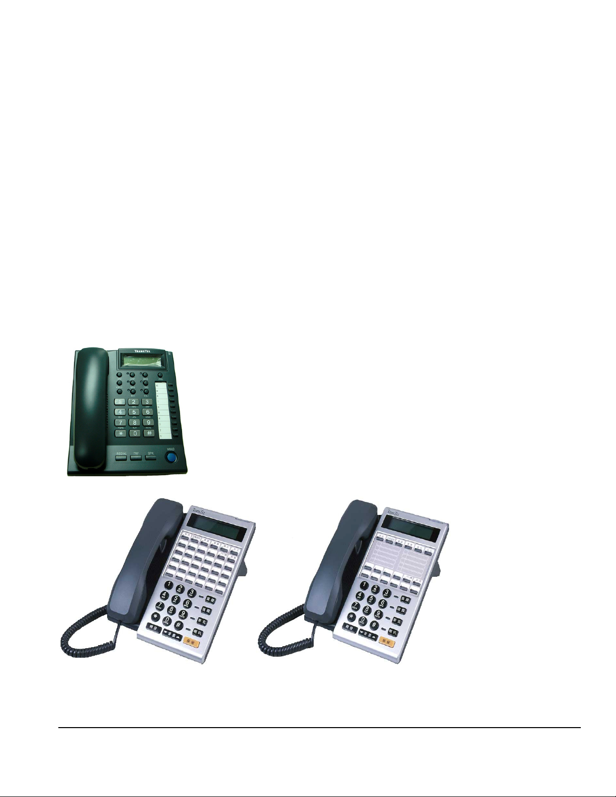
Liquid Crystal Display
The DK Series Telephone Model DK6 and DK7 phones are equipped with a large, easy to read LCD display. The
LCD is 32 characters total, comprised of 2 rows by 16 characters each. This LCD provides an invaluable tool for
simplifying the use of the telephone by identifying the calling extension by name, outside lines by name and self
prompting displays for feature access. Station feature usage is made simple with the help of the LCD display.
Continuous prompting information is displayed during calls so that users know what to do and when to do it.
32/64-character LCD Display shows:
• Time • Last number dialled
• Dialed telephone number • The status of operation/function
• Voice Mail Messages • Absent messages
• CO Line Names • Speed Dial Directory
• Last Number Redial • Calling Party Number and Name
• Speed dial number • Input data during system data entry
TransTel Telephone Model DK7
DK-7
DK6-36 DK6-18
LYNX Plus Programming Manual Rev 2.1c Page
19
Page 20

Specifications
MAXIMUM LOOP RESISTANCE/IMPEDANCE
Key Telephone Less than 40 ohms 26 AWG / 200 m
Single Line telephone Less than 800 ohms 26 AWG / 800 m
DoorPhone Less than 40 ohms
INTERNAL RELAY CONTACTS
Type SPST
Rating 1 AMP, 24VDC
Function Door Switch, Music on Hold, etc
CABLE REQUIREMENTS
CO/PABX Line Twisted 1 Pair (2 wires)
ISDN BRI Twisted 2 Pair (4 wires)
DK1 Digital Key Telephone Twisted 1 Pair (2 wires)
Doorphone Twisted 1 Pair (2 wires)
Door Switch Twisted 1 Pair (2 wires)
External Sensor Twisted 1 Pair (2 wires)
Single Line Telephone Twisted 1 Pair (2 wires)
Mechanical Specifications (Key Service Unit)
CABINET DIMENSIONS
425mm W 85mm D 315mm H
16.7” 3.3" 12.4"
WEIGHT 3.9 Kg (Configuration: 4 x 8)
8.59 lbs
Mechanical Specifications (Battery Back Up Housing)
CABINET DIMENSIONS
36 cm W 13 cm D 44 cm H
WEIGHT With Batteries -16 lbs Without Batteries- 4 lbs.
Mounting Screws 12.25” centre to centre
Environmental Specifications
OPERATING CONDITIONS STORAGE
Temperature 0º to 30º C -40º to 66º C
(32º to 86º F) (-40º to 150º F)
Humidity 10 to 95% relative 10 to 95% relative
Non-condensing non-condensing
CONDITIONS
Page 20
Page 21

Features
System Features
Account Code Capability
Attendant Console Assignment
Attendant Overflow
Automatic Line Access
Automatic Line Search
Automatic Ringdown
Automatic Wake-up
Battery Charger
Behind PABX Operation
Centrex Operation
Class Of Service
CO Line Groups
CO Line Hunting
CO Line Name Programming
CO Line Ring Types
Linear
Common Audible
Circular
Hunt
Console Assignment
Day/Night Service
Manual/Automatic Switch
Dial 9 Group
Direct In Line
Dial By Name
Dial Mode Selection(DP/DTMF)
Dial Pulse to DTMF Conversion
Distinctive Ringing
DTMF Signalling
Dual Port Capability
End to End Signalling
Easy Installation and Operation
Flash (Programmable)
Flash Memory Backup Memory
Flexible Expansion
Host PABX Access
Hot line
Line Group Assignment
Loud Bell Assignment
Multiple Attendant Consoles
Multiple Trunk Groups
Night Transfer
On Call Programming
Paging
Internal
Zone
Meet Me
Password Assignment
DISA
System programming
Toll Override
Pause
Pick Up Groups
Power Fail Transfer
Security Code
Single Digit Dialling
Station Group Assignment
Station Hunting
Station Lock
System Speed Dial and Personal Speed Dial
System Date & Time Setting
System Time-Reminder Service
Telephone Directory
Toll Control
Day / Night
Tone to pulse dialling
Trunk Queuing
Trunk to trunk connections
Uniform Call Distribution
Voice Mail Compatibility
Flexible Ringing Assignment
Flexible Key Group Assignment
Flexible Number Plan 2,3 or 4 Digit
Flexible Time Format 12/24 Hour
Forced Account Code Assignment
Intercom
Intercom Single Digit Assignment
Intercom Ring / Voice Select
Intercom Dialling Restriction
LYNX Plus Programming Manual Rev 2.1c Page
21
Page 22

Station Features
Advisory Messages
Access to System Programming
Account Code Capability
Auto Hold
Auto Hold Recall
Automatic Call Back
Automatic Answer-Intercom
Automatic Line Access
Automatic Redial
Automatic Volume Increase
Brokers Call
Call Duration Timer (LCD Phones)
Call Waiting
Call Forwarding
All Calls
Busy
No Answer
Busy / No Answer
External
Call Pickup
Call Split
Call Transfer
Calling Name Display (LCD Phones)
Calling Number Display (LCD Phones)
Camp On
Chain Dialling
Conference
Dial By Name (LCD Phones)
Dial Access to Attendant
Direct Station Selection
DoorPhone Access
Do Not Disturb (DND)
Dual Color LED
Duration Time Display (LCD Phones)
Executive Override (Barge-In)
External Call Forwarding
Flash (Open Loop Timed Flash)
Hands-free Answer Back
Hearing Aid Compatibility
Headset Compatibility
Hold (Exclusive / System)
Hold Recall
I Hold Indication
I Use Indication
Intercom
Intercom ring / voice interchange
Intercom Step Call
Intercom Voice Announce
Last Number Redial
Message Waiting
Multi-Language Display
On Hook Dialling
Page 22
Page 23

Parts & Peripherals
System Modules
Model Description
G1-KT-308P KSU with 3 CO lines, 4 Digital ports and 4 Slt ports with CLIP (Caller ID) function
RS232/Relay/Sensor
G1K-TLU Trunk/Single Line Card : 2 CO lines and 4 SLT ports / with CLIP (Caller ID) function
Type of Phones
Model Description
DK7-21 Multifunction Key Telephone. Includes 32 character LCD display, speakerphone,
Handsfree, headset jack, 10 dual color keys and 14 function keys for feature access,
DSS, CO Lines and speed dial.
DK6-36 Multifunction Key Telephone with 2 line LCD display, speakerphone, Handsfree,
headset jack, 36 dual color keys and 7 function keys for feature access, DSS, CO
Lines and speed dial.
DK6-12 Multifunction Key Telephone with 2 line LCD display, speakerphone, Handsfree,
headset jack, 12 dual color keys and 7 function keys for feature access, DSS, CO
Lines and speed dial.
DPU1 Digital Door phone – weather resistant
ACP/RF Access Control Phone with RF Proximity Card function
PX-Card RF Proximity Card for ACP/RF
WMU-x Wall Mount Kits for DK Series Telephones
Peripheral Devices
Model Description
BBOX0 Battery Box without Batteries
BBOX1 Battery Box with Batteries
Optional Interface Cards
Model Description
G1K-NFC128M
2 Channel Voice mail card
LYNX Plus Programming Manual Rev 2.1c Page
23
Page 24

Page 24
Page 25
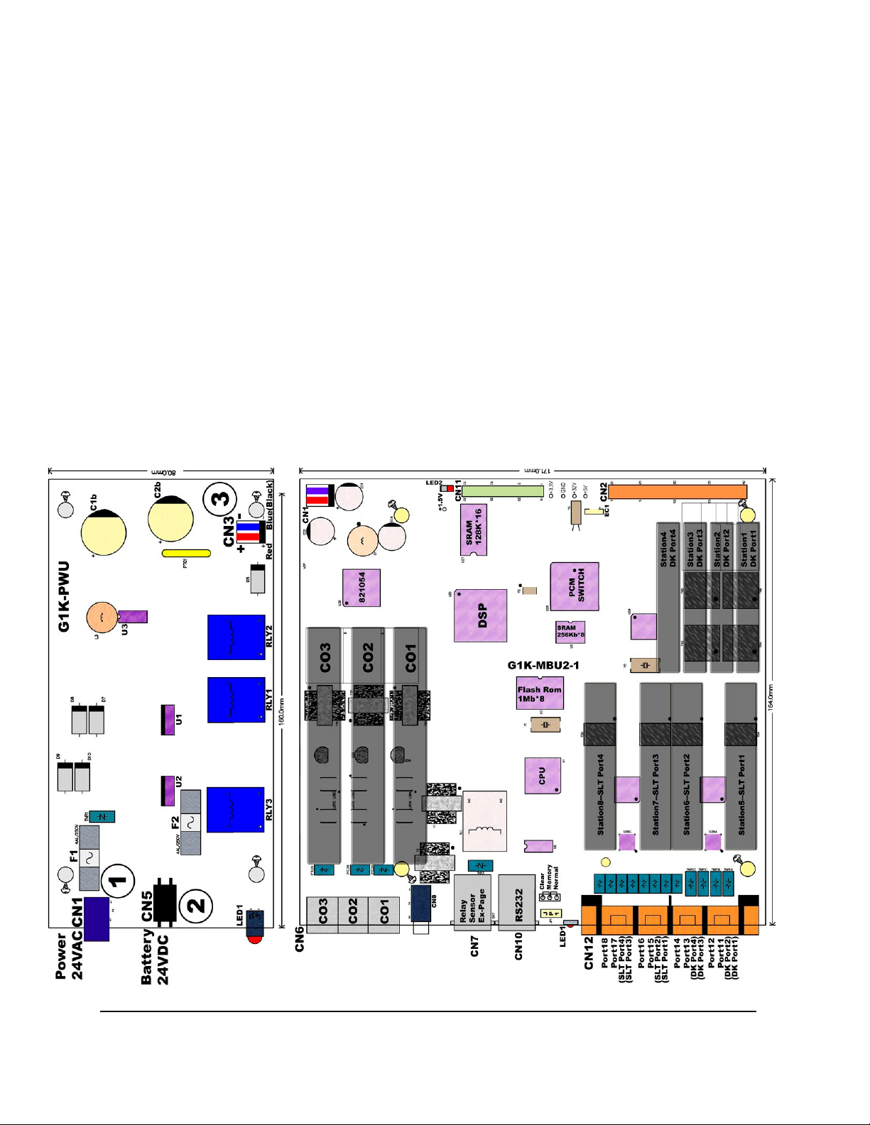
System Installation - Introduction
This section provides directions for installing the system and optional equipment.
The installation must be performed by qualified service personnel.
Main components of the system are:
Key Service Unit, which includes:
• Power Supply Unit (G1K-PWU)
• Main Board Unit (G1K-MBU2 / Common Control,
4 digital port circuits and 4 SLT ports) On board
messaging and Auto Attendant.
NOTE: Please follow the directions step by step. The Lynx system should be installed in strict
accordance with this manual.
Optional Expansion Cards:
• TLU Card (2 CO + 4 single line port circuits)
LYNX Plus Programming Manual Rev 2.1c Page
25
Page 26

Site Requirements
Location
Choosing the Right Environment
• System should be installed in a clean, dry, secure location. This location must have adequate
ventilation, and a temperature from 0 to 30 (32 to 86), with 10% to 95% non-condensing
relative humidity. DO NOT install the equipment near sources of static electricity, excessive vibration,
or water. Avoid direct sunlight.
Installation Checklist
INSTALLATION REQUIREMENTS VERIFICATION
MOUNTING SURFACE Flat surface with adequate space for main cabinet,
power supply, wiring and optional Battery Backup
cabinet.
AC LINE AC line should be dedicated exclusively to the system.
POWER OUTLET Power Outlet must be a 3-wire grounded outlet plug.
The socket outlet shall be installed near the system and
be easily accessible.
Input power Line capacity requirements - 10 amperes.
CAUTION DOUBLE POLE/NEUTRAL FUSING ON
EUROPEAN PLUGS
SURGE PROTECTION A Surge Protector is recommended on the dedicated AC
line.
VENTILATION AND TEMPERATURE Humidity: 10% to 95% relative non-condensing
Temperature:32 to 113 (0 to 45 ).
EARTH GROUND A proper ground connection. (14 AWG)
SERVICEABILITY Lighting conditions and working space adequate for
future service.
Equipment Requirements
• Unpack, Check and Verify Equipment - Unpack the telephone equipment boxes and verify the
contents in accordance with the packing list provided. If any discrepancies are noticed, please contact
TransTel Communications, Inc. or Authorized Dealers.
• Damaged Boxes - If you notice any damage to the packages, please notify both the shipper and
TransTel communications, Inc. or Authorized Dealers at once.
• List of parts included in basic KSU box:
• KSU Main Cabinet
• Mounting Template
• Mounting Screws
• Station Quick Connectors
• Spare Fuses
• Cable Cover
Installation
Caution
1. This system should be installed by qualified service personnel.
2. Do not install the Power Supply unless you have read the following instructions and
completed all the installation and wiring.
Page
26
Page 27
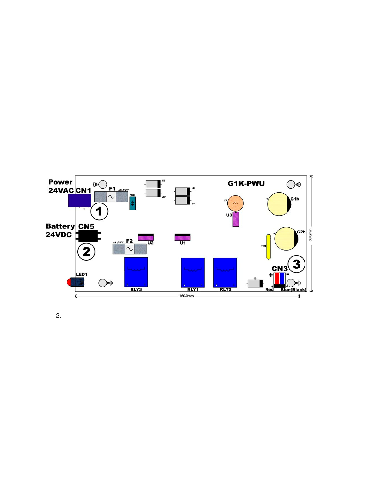
3. STATIC SENSITIVE DEVICES! Please handle with care.
Installing expansion and optional cards
In this step you will be installing printed circuit cards on to header pins of the main board in the basic
cabinet. Take your time and extra care to assure the printed circuit cards are properly aligned. After
installing each option and expansion card, perform a visual inspection to assure the printed circuit card is
installed properly.
1. Position the cabinet on a flat surface like a table or countertop. Avoid doing this on carpet.
2. Remove the 4 screws located at the corners of the cabinet and lift the front cover off.
3. Locate the expansion and option cards and unpack them at this time.
Card Introduction
G1K-PWU-Power Supply Interface Card
1. CN1: AC 24VAC Input
2. CN50: Battery Connection +24V to +27V DC
3. CN3: Cable connection from G1K-PWU to G1K-MBU CN1
4. LED1: G1K-PWU DC +24V indication
5. F1/F2: 4A/250V
LYNX Plus Programming Manual Rev 2.1c Page
27
Page 28
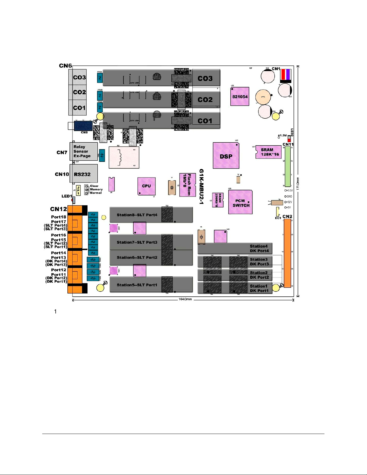
G1K-MBU2 Main Board Unit
1. CN1: Power connection to G1K-PWU CN3
2. LED2: DSP operation indication when slow flashing is normal
3. CN11: To G1K-NFC 128 CN1
4. EC1: Gold capacitor which provided for Real Time Clock
5. CN2: To G1K-TLU CN1
6. CN6: CO 1~CO 3 input from Central Office
7. CN8: External Music
8. CN7: Relay/Sensor/Ex-Page
9. CN10: RS232 connection
10. JP1: Clear Flash Memory / Normal Operation
11. LED1: System operation indication when slow flashing is normal
12. CN12: Connections for Digital Ports 11~14 (ST1~ST4) and SLT Ports 15~18 (ST5~ST8)
Page
28
Page 29
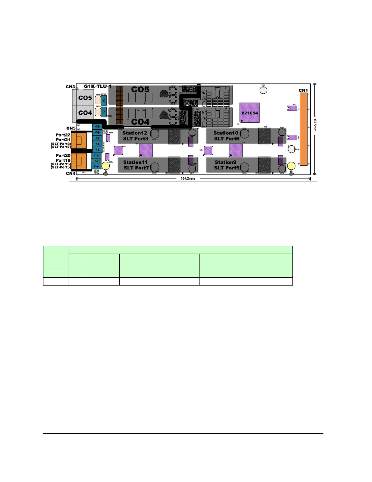
G1K-TLU 2 Port CO Line and 4 Port SLT
CN1: To G1K MBU CN2
CN3: CO 4 and CO 5 input from Central Office
CN5: Connections for SLT port 19, 20 (ST9~ST10)
CN4: Connections for SLT port 21, 22 (ST11~ST12)
G1K-NFC 128
CF Card G1K-NFC (32kbps) G1K-NFC (16kbps)
128M
Total 1 Unit Duration Duration Total 1 Unit Duration Duration
Unit Duration (mins) (hours) Unit Duration (mins) (hours)
(secs) (secs)
For a description of the VMU and Auto Attendant setup and configuration including how to record
messages see the section at the end of the Installation Manual
LYNX Plus Programming Manual Rev 2.1c Page
29
Page 30
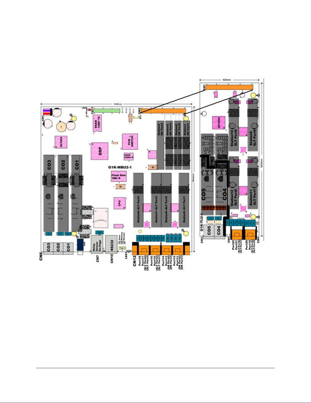
Install G1K-TLU 2 CO line 4 port SLT
Power off the system before installing card
Install 2 spacers to the MBU by removing screws from the MBU and replacing with spacers
Align CN1 of the G1K-TLU card with CN2 of the G1K-MBU.
Align the hole on right side of G1K-SLU with the standoff.
Page
30
Page 31

Installing the Equipment
Backboard
Be sure to plan and allow enough space to
mount and connect the key service unit, power
supply and system battery back up if applicable.
Mounting Tabs
Key Service Unit
Use the enclosed paper template to locate the
mounting position for the Key Service Unit. Drill
Wall or backboard
Key Service Unit
appropriately spaced holes and mount the KSU
on the wall. When mounting the KSU, make certain that there is adequate room for the system power
supply and that the connecting cable between the Power Supply and the KSU will reach the KSU. The
same applies for the battery back up unit.
Power Supply
Dedicated Power Source - The power supply must be connected to a dedicated AC outlet.
Be sure that the third wire earth ground of the AC circuit is connected to a good electrical ground. If a
music source is installed, it must be connected to a separate AC circuit rather than the system's dedicated
AC line cord.
Check Your power adapter
Verify that the input voltage and power adapter input voltage are correct before you connect and power on
the system. The input voltage is set according to the Customer's requirement before shipping. However it
is important to verify that the setting is correct prior to initial system power up.
Power adapter supply voltage options for the
unit:
100-VAC: 100 to 120 V AC (50/60Hz) or 240VAC: 205 to 265 V AC (50/60Hz).
Mount Power adapter
Using screws provided with the system, mount
the power adapter close to the KSU so that the
connector reaches from the Power Supply to the
KSU.
Preparing The External Battery Backup
The Key Service Unit uses one external backup battery unit containing 2 x 12v batteries in series (24
volts) for emergency power when a power failure takes place.
If you are installing an optional Battery Backup (BBOX1), make certain that there is adequate room for its
installation. Make certain that the Battery Backup is mounted close enough to the Power Supply that the
interconnecting cable between the Battery Backup and the Power Supply can connect.
Do Not Connect the Battery Backup at this time!
Do Not Connect the Battery Backup at this time! Battery Backup should not
be connected to the System power supply until all power up testing has
been completed!
LYNX Plus Programming Manual Rev 2.1c Page
31
Page 32

Charging the Battery
The rechargeable batteries are automatically charged when the KSU is plugged in.
When System is in a full-load condition (seven CO Trunks and 16 Extensions all in use), the batteries
provide a minimum of 1 hour's consecutive use. Change the batteries every two years.
Installing or Replacing Batteries
Caution
To Reduce the Risk of Fire or Injury to persons, Read and Follow these Instructions.
1. use only the following type and size batteries:
12 Volt 6.5 Amp/Hour "Gel-Cell" sealed batteries (2).
Dimensions, approximately 3 1/4" (H), 5 15/16" (W), 2 1/2" (D).
Power Sonic model PS660 or equivalent.
2. Do not dispose of the batteries in a fire. The cell may explode.
3. Check with local codes for possible special disposal instructions.
4. Do not open or mutilate the batteries. Released electrolyte is corrosive and may
cause damage to the eyes or skin. It may be toxic if swallowed.
5. Exercise care in handling batteries in order not to short the battery with conducting
materials such as rings, bracelets, and keys. The battery or conductor may overheat
and cause burns.
This product is defined as a secondary battery operated device. As such, the following
instructions should also be read and followed:
1. Charge the batteries provided with or identified for use with this product only in accordance with the
instructions and limitations specified in this manual.
2. Observe proper polarity orientation between the batteries and battery charger.
3. Do not mix old and new batteries in this product.
4. Do not mix batteries of different sizes or from different manufacturers in this product.
Before installing or replacing batteries, disconnect the battery supply unit to the KSU by removing the
polarized battery connector at the KSU. Due to the weight of the batteries, it is advised that the battery
cabinet be removed from the wall before working on it.
KSU Connecting (Main) Panel Layout
The following illustration should be used as a reference when connecting equipment to the Lynx KSU.
Refer to the wiring diagram located on the inside of the cable cover for all connections
Connecting Stations
The station cabling for the Lynx should be a home run from the jack to the telephone room. The
termination should be at conventional 66 type connecting blocks or Krone blocks or directly to the provided
station connectors. One pair twisted wiring is required for each station location. The Lynx station ports
are not digital twin ports and each station must be a home run to either the inner or outer pair of each DDK
Page
32
Page 33

connector. Attention to proper cabling will go a long way towards a successful installation and minimizing
service calls after installation. Some guidelines for running station cable are as follows:
Avoid running cable parallel to fluorescent light fixtures or electrical lines not in conduit. If these
obstacles are unavoidable, run the cable at right angles across them.
Do not run station cable inside conduit already occupied by electrical wiring.
Do not run station cable near equipment with electric motors or strong magnetic fields.
Do not place station cable on the ground where it can be stepped on or rolled over by office furniture
or office equipment.
Digital Key Telephone –DK6 - DK7
A cable cover is provided with the KSU. Station cables enter from the bottom of the KSU. Remove
the cover and route the station cable through the hole. Terminate the station wires with the
connectors that are provided. The stations will connect to the KSU as shown on the main panel
(above) on connector locations ST1~ST4 (port11~port14).
Connect the stations to Inner pair for Port 1 and outer pair for Port 2 of the DDK connector.
Connect Tip terminal with GRN terminal (screws) of the modular jack, Ring with RED.
There is no polarity requirement on Tip and Ring.
2-conductor wiring is required for DK series Digital Key Telephones.
Select the 1st station position. ALL phones are to be set to this position for the Lynx
For DK6 and DK7 phones the switch is on the underside of the phone and should always be set to
first position.
CAUTION!: Avoid shorting Tip and Ring together. It may damage the G1K-MBU or G1K-TLU board.
LYNX Plus Programming Manual Rev 2.1c Page
33
Page 34
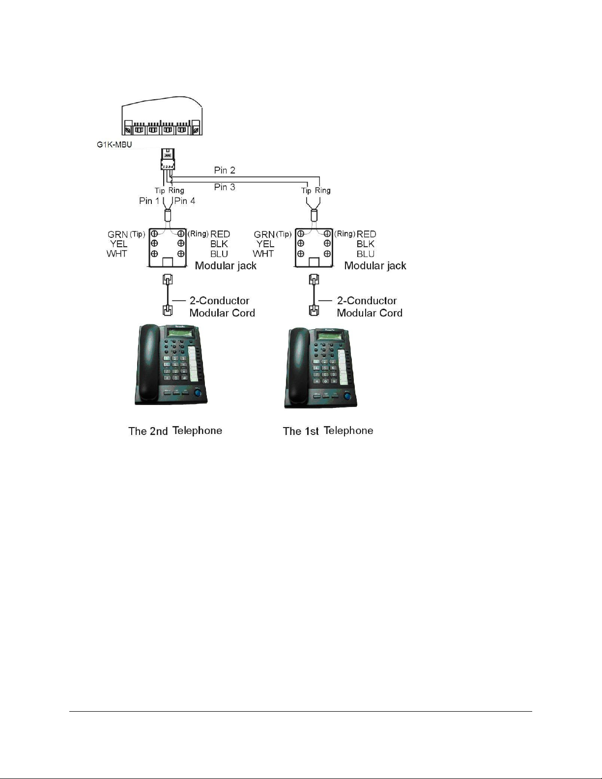
Page
34
Page 35

Access Control Telephone/Door Phone – ACP/DPU
A cable cover is provided with the KSU. Station cables enter from bottom of the KSU. Remove the
cover as required and route the station cable through the hole. Terminate the station wires with the
connectors that are provided. The stations will connect to the KSU as shown on the main panel
(above) on connector locations ST1~ST4 (port11~port14)
Connect Tip/Ring terminals from KSU (G1K-MBU) to the ACP/DPU connector (6 contacts).
There is no polarity requirement on Tip and Ring.
Connect Relay for applications such as door open to the ACP/DPU connector (6 contacts).
Connect Sensor for applications such as door open alarm to the ACP/DPU connector (6 contacts).
Mount ACP connector on to ACP/DPU itself.
Select the 1st station jumper as shown in diagram below.
Mount ACP/DPU on the wall.
CAUTION!: Avoid shorting Tip and Ring together. It may damage the G1K-MBU board.
LYNX Plus Programming Manual Rev 2.1c Page
35
Page 36

Single Line Telephone (connected to G1K-MBU)
Station cables can enter from the bottom of the KSU. Remove the cover and route the station cable
through the hole. Terminate the station wires with the connectors that are provided. The stations will
connect to the KSU as shown on the main panel (above) on connector locations ST5~ST8
(port15~port18) or ST9~ST12 (port19~port22) (Needs G1K-TLU installed).
Connect Tip terminal with GRN terminal (screws) of the modular jack, Ring with RED.
There is no polarity requirement on Tip and Ring.
2-conductor wiring is required for Single Line Telephones.
CO/PABX Connections
Make your CO line connection to the telephone company on this connector. Pins 3 and 4 of the
connector are for the CO line.
RJ-11C (2 wire) modular connector is required.
2-conductor wiring is required.
Music on Hold Connection
• Conn
ect the (optional) external music source to the external Music input labeled on the KSU.
• Use a 1/8” mini plug to connect the music source to the KSU via an approved line isolation unit.
Page
36
Page 37

Optional Cabling
Connect a 6 conductor mounting cord from the KSU to a RJ-25 modular block.
Door Switch (Relay) Connection
One Door Switch (24+-12VDC) may be used on the G1K-MBU.
2-conductor wiring is required.
Connect the door switch to pins 1 and 6 of the RJ-11 connector.
Sensor Connection
The Sensor connector on G1K-MBU may be used for the External Sensor input.
The sensor may be configured for normally open or normally closed operation.
2-conductor wiring is required.
Connect the sensor to pins 2 and 5 of the RJ-11 connector.
Refer to System Programming Mode 39 -- Sensor Assignment.
LYNX Plus Programming Manual Rev 2.1c Page
37
Page 38

RS232 Port Connection
Use the RJ-11 connector to terminate the RS232 cable. Then connect the RJ-11 to the KSU with a 6
conductor line cord. Insert the line cord into the connector labeled RS-232.
Notice: Do not exceed the cable length limitation (15M / 50 feet.) for the RS232 connection
VMU Setup
The G1K-MBU contains a G1K-NFC card 2 Channel Auto Attendant with voice messaging. Also included
is a 2 minute MOH section. In Default the MOH is pre-recorded with copyright free music.
Messages are recorded in G1K-NFC Flash Ram and do not require any battery backup to maintain.
For a description of this procedure see mode 25 in the Programming manual
To access the MBU Flash Ram to setup or record messages dial 89 from the Console.
External Music on Hold Source
The Lynx system has an external Music port but relies on using the 2 Minute MOH message recorded on
the G1K-NFC Flash ram. This message can be recorded by the customer to allow them to use their own
message or used to connect an external Music source if required.
1.
Connect music source to external music port.
2.
05-08-08= 4/5 (4= BGM uses Internal music and HOM uses external music, 5=BGM and HOM uses
external music port).
Page
38
Page 39

Power On and Operational Test
Before connecting the G1K Power Adapter to AC power:
Verify that input voltage and Adapter input voltage are correct before you power up the system.
Recheck the cabling for incorrect connections, loose wires and wiring fragments that may cause
short-circuits.
Plug the power adapter cord into a power outlet.
Verify the system boots properly by checking the display of a telephone set.
You may now connect the battery back up unit if applicable.
Operational Tests
Check each telephone and CO line to verify that outgoing lines are connected properly.
Check that intercom calls can be made from extension to extension.
WARNING:
DISCONNECT THE POWER SUPPLY FROM THE AC POWER SOURCE BEFORE WIRING OR
CHANGING ANY WIRING.
Connect the Battery Backup AFTER AC power has been connected to the Power Supply.
Disconnect Battery Backup BEFORE disconnecting AC power from the Power Supply.
NOTICE:
ONCE THE SYSTEM OPERATES PROPERLY, PROCEED TO SYSTEM PROGRAMMING.
(REFER TO THE SYSTEM PROGRAMMING MANUAL.)
Special Immunity Protection for System and terminals
Adding Noise Filters to the points below can enhance the immunity capability of the system from outside
environmental noise.
For Line:
LYNX Plus Programming Manual Rev 2.1c Page
39
Page 40

Page
40
Page 41

Introduction
The manual contains all the parameters that could be flexible programmed inside the LYNX+ Hybrid IP
Telephone System.
New Systems
We recommend that all new systems have the system memory reset before system programming takes
place. This ensures that any extraneous information that may be present in system memory is erased
and that the system database will not be corrupt for unpredicted data.
To reset the database in LYNX+, from a LCD display phone to enter programming by pressing [PRG], [2],
Enter Password if programmed. (New systems will not have a system password), so, press [SAVE] key
then you will see the LCD display as follow:
PROGRAM MODE: __
(01 – 95)
25- Reset Data
0-9 Default
You may begin database entry at this point or exit system programming by pressing [SPK] key or by lifting
and replacing the handset.
A station can access the trunk line and talks on a phone when entering system programming mode. This
allows a technician to guide a customer into program mode and make minor changes by programming the
system data during their conversation.
Note: Before Powering Down the Lynx System please complete following entry from any DK7 Phone.
“Prog Hold #”
This will tell the system to backup any customer data in its RAM Memory.
Then enter [2] [5] and press [SAVE]. You will be in Program Mode 25-
01. The display will show:
Enter [2] to reset entire data and phone will beep and return to the
previous screen.
LYNX Plus Programming Manual Rev 2.1c Page
41
Page 42

Basic Programming Commands
Enter Programming:
To begin database programming in LYNX+ from a LCD display phone, press [PRG], [2], Enter Password if
programmed. (New systems will not have a system password). Press [SAVE] key then you will see the
LCD display as follow:
PROGRAM MODE: __
(01 – 95)
You may now enter the programming Mode (form) you wish to program in the system. When you have
entered the two digit mode, you may need to enter additional digits to access a specific sub-form and Item
Pointer (IP).
Note: Keys listed between [ ] indicate the default keys shown on a telephone set. Keys listed
between { } indicate the effect they have on programming.
These commands are active while in the system programming mode
[PRG] {PRG}: Moves to the Top Level Programming Mode Display (does not save
information entered into any field unless [SAVE] is pressed first).
[SAVE] {SAVE}: Commits the data that is shown on the LCD display into the system
database.
[DSS 1] {PREVIOUS}: Moves to the previous section of any multiple part form.
[DSS 2] {NEXT}: Moves to the next section in any multiple part form.
[DSS 3] {CURSOR LEFT}: Moves the programming cursor to the left position.
[DSS 4] {CURSOR RIGHT}: Moves the programming cursor to the right position.
[DND/CN] {DON’T CARE}: Enters a Wild Card (don't care) into Account Codes or Toll
control entries. LCD will display d (lower case letter "d") to indicate don't care entry.
[HOLD] {PAUSE}: Inserts a Pause when programming a Speed Dial Entry or for Voice
Mail Programming. LCD will display p (lower case "p") to indicate a Pause entry.
[TRF/FL] {FLASH}: Enters a FLASH command as part of a Speed Dial Entry. LCD will
display F (upper case "F") to indicate a Flash command. This key also means clears a
digit during other entries (Passwords, etc).
[MSG] {PULSE > TONE}: Enters a command to convert from pulse dialling to DTMF
dialling into a Speed Dial Entry. LCD will display T (upper case "T") to indicate a tone
conversion command.
[MIC/AT] {CHANGE}: CHANGE key. Depending on the form, it will toggle through
available Programming parameters.
[TRF/FL] {CLEAR DIGIT}: Enters a FLASH command as part of a speed dial number.
This key also means clears a digit during other entries (Passwords, etc).
[SPK] {EXIT}: Exits Programming. Returns telephone to normal idle mode.
Page
42
Page 43

[REDIAL] {CLEAR ALL}: Clears all digits on an entry such as speed dial or account
codes.
Alphanumeric Entry:
The following table indicates the capabilities of the name programming functions if they are selected on
the system. System Speed Dial, Personal Speed Dial, Stations, CO Lines and Sensors may be
programmed with names.
Key 1 = (Blank Space) – 1 Key 2 = A - B - C – 2
Key 3 = D - E - F – 3 Key 4 = G - H - I – 4
Key 5 = J - K - L – 5 Key 6 = M - N - O – 6
Key 7 = P - Q - R - S – 7 Key 8 = T - U - V – 8
Key 9 = W - X - Y - Z – 9 Key 0 = (Period). : & – 0
Key # = ( ) $ # Key * = (Dash) / ! *
DSS Key 1 = Backspace Cursor (Left) DSS Key 2 = Cursor Forward
If an entry is made that is not within valid system parameters, the system will not accept the entry when
[SAVE] is pressed. The Speaker on the programming set will return a busy tone and the LCD Display will
place the programming cursor under the invalid entry. You may make corrections and press [SAVE]
again. If multiple errors are made, the system will continue to return you to the illegal entries until they are
corrected.
It is not necessary to re-enter existing information on a multi-item form. You need enter only the
information that is to be changed. You may move the cursor to the left or right in order to access only the
specific entry that you want to change. You may press [SAVE] without regarding for the placement of the
cursor on the LCD display.
DK6 Key Telephone – Key Layout (36 Button)
LYNX Plus Programming Manual Rev 2.1c Page
43
Page 44

DK6 Key Telephone – Key Layout (18 Button)
DK7 Key Telephone – Key Layout
Page
44
Page 45

LYNX System Setup
The LYNX system has been setup to enable it to be plugged in and turned on to enable a customer to use
the system with little or no Programming changes.
The following details some of the points you should be aware of, please refer to your Manual for more
detailed information.
Numbering Scheme
• Dial 9 for outside line
• Dial 0 for Operator Position
• Extensions: 11 – 18 with standard System, with expansion card 19 – 22 will be added
• Virtual Extensions 41 and 42 can be used as Voice Mail Answer points
• Dial 89 to Record Main System Greetings (From Console, Ext 11)
• Dial 86 for Extension Voice Mail
Ringing Assignments
• Extension 11, 12, 13, and 14 will ring on all incoming calls in Day Mode
• Extension 11, 12, 13, and 14 will ring on all incoming calls in Night Mode
• Faxibility setup on Line 3, by default Fax call will ring extension 18
General Setup
Digital extensions 11,12,13, and 14, analog extensions 15 and 16 and virtual extensions 41 and 42 have
Voice Mail assigned
• SLT Hook Switch Time on System set to 600ms
• Centrex / Gateway Flash Time set to 800ms
• MOH will use VMU Card
• System Enabled for Clear Forward (Please note if your country uses AR you must enable)
• Hot Keys enabled of System Phones
• Toll COS 0 Allows all calls
• Toll COS1 setup to Bar Toll calls but allow 0800 and 0508
• Toll COS 2 setup to Restrict International Call
LYNX Plus Programming Manual Rev 2.1c Page
45
Page 46

Program 01-tk-IP : Day Ringing And Ringing Line Preference Assignment
01-tk-IP FLX DAY
11 12 13 14
General:
This program assigns each incoming line to ring the programmed stations. The ringing methods can be
LINEAR (ring the first available station), CIRCULAR (Ring the next station following the last station who
just answered an incoming call), HUNT (Ring the first assigned station for a set period of time (program
mode 05-08-01) then if no answer ring the next ring assigned station then the next etc.) or COMMON
AUDIBLE (All stations will ring simultaneously). See Program Mode: 35-tk-07 to assign. An overflow Ring
Hunt Group can be assigned to make additional stations ring after a time interval in addition to this ring
assignment. See program Mode 29-07/08.
Description:
1. This program sets Day Time ringing.
2. The station number can be 2,3,4 digits.
3. A total of 26 stations can be assigned to ring for each trunk.
4. If the location is to be assigned to no station, the location value is set to " 0 ".
5. To clear all entries press [REDIAL].
6. Lunch ringing is programmed in Mode 94.
Note: Faxibility on Line 3 set to ring Extension 18.
tk=Trunk No. (01-12), IP=Item Pointer (01-26)
Assigned station number
Program 02-tk-IP : Night Ringing And Ringing Line Preference Assignment
02-tk-IP FLX NIG
11 12 13 14
tk=Trunk No. (01-12), IP=Item Pointer (01-26)
Assigned station number
General:
This program assigns each incoming line to ring the programmed stations. The ringing methods can be
LINEAR (ring the first available station), CIRCULAR (Ring the next station following the last station who
answered an incoming call), HUNT (Ring the first assigned station for a set period of time (program mode
05-08-01) then if no answer ring the next ring assigned station then the next etc.) or COMMON AUDIBLE
(All stations will ring simultaneously). See Program Mode: 35-tk-08 to assign. An overflow Ring Hunt
Group can be assigned to make additional stations ring after a time interval in addition to this ring
assignment. See program Mode 29-07/08.
Description:
1. This program sets Night Time ringing.
2. The station number can be 2,3,4 digits.
3. A total of 26 stations can be assigned to ring for each trunk.
4. If the location is to be assigned to no station, the location value is set to 0.
5. To clear all entries press [REDIAL].
6. Lunch ringing is programmed in Mode 94.
Page
46
Page 47

Program 03-01-IP : Door Phone Ringing Assignment
03-01-IP Door
11 12 13 14 15
General:
This program assigns the Door Phone/s to ring the programmed stations.
Description:
1. To assign an ACP or digital door phone to follow Mode 03 it must be set to “d” in mode 46-st-07.
Otherwise it will ring the stations assigned in the Hunt Group allocated in mode 46-st-07
2. Twenty six stations can be assigned to ring for the door phone.
3. To clear all entries press [REDIAL].
4. Door phone ringing time is set in Mode 05-11-07.
5. Door Relay Unlock Time is set in Mode 05-12-04.
6. Door phone Ringing frequency is set in Mode 05-03-08.
IP = 01-26
Assigned station number.
Program 04-gp-IP : Console Assignment
04-gp-IP Console
11 00 00 00
General:
This program permits the selection of the consoles in each station group. Consoles are stations that can
program System speed dials, Record system Voice messages, receive hold recalls and ring when callers
dial 9/0 for the operator. For DISA calls only the ring type is Common Audible otherwise Linear is standard
Description:
1. There are 8 console groups available. Four stations can be set in each group
2. Assign either a station or the pilot number of a hunting group as the console(s).
4. The first assigned station is the master console if a pilot number is assigned here.
5. Only the Console can operate some special Voice Mail features.
6. To clear all entries press [REDIAL]. Do this in ALL unused groups.
gp = Station group (01-08) IP = (Item Pointer) 01-04
Assigned station number (2 to 4 digits)
LYNX Plus Programming Manual Rev 2.1c Page
47
Page 48
Program 05-01-IP : System Timing Parameters – 01
05-01-IP SYS PAR
1 1 1 1 4 2 2 1
IP=Item Pointer (01-08)
Value for each Item
IP Value Default Item Description
01 0-9 1= 60 sec. Hold Recall Time
02 0-9 1= 60 sec. Exclusive Hold Recall Time
03 0-9 1= 60 sec. Hold Recall Timeout
04 0-9 1= 2 sec. DISA & ECF Access Delay Time - Day
05 0-9 4= 8 sec. Busy Remind Cycle Time
06 0-9 2= 800 ms Pause Time
07 0-9 2= 83 ms DTMF Generation Time
08 0-9 1= 20 sec. Call Forward No Answer Transfer Time
01. Hold Recall Time
This parameter set the time duration from the line is put on Hold to this held call recalls the station.
After a pre-determined recall time (see 05-01-03: Hold Recall Timeout), if the called station still does not
answer, the held call will be automatically transferred to the Console.
IP \ Value 0 1 2 3 4 5 6 7 8 9 Unit
05-01-01 30 60 90 120 150 180 210 240 253
Note: ∞ = Infinite. It means no Hold Recall.
02. Exclusive Hold Recall Time
This parameter sets the time duration from the line is put on Exclusive Hold to the held call recalls the
station.
After a pre-determined recall time (see 05-01-03: Hold Recall Timeout), if the called station still does not
answer, the held call will recall to the Console in addition to the station that put this line on Exclusive Hold.
IP \ Value 0 1 2 3 4 5 6 7 8 9 Unit
05-01-02 30 60 90 120 150 180 210 240 253
Note: ∞ = Infinite. It means no Exclusive Hold Recall.
03. Hold Recall Timeout
This parameter sets the timer between a held call recalling to a holding or transferring station and then
recalling to the console if unanswered.
IP \ Value 0 1 2 3 4 5 6 7 8 9 Unit
∞
∞
sec.
sec.
05-01-03 30 60 90 120 150 180 210 240 253
Note: ∞ = Infinite. It means no Hold Recall to console.
Page
48
∞
sec.
Page 49

04. DISA & ECF Access Delay Time - Day
This parameter sets the timer that a DISA/ECF (External Call Forwarding) trunk will ring assigned stations
(set by Program 01-tk-IP, 02-tk-IP) prior to be connected to Auto Attendant (DISA) or another Trunk (ECF)
in Day mode. Stations can answer the incoming trunk before it is connected to Auto Attendant or another
Trunk.
IP \ Value 0 1 2 3 4 5 6 7 8 9 Unit
05-01-04 0 2 4 6 8 15 30 60 120 254 sec.
Note: 0 = Incoming trunk connects to Auto Attendant or another trunk without ring those assigned
stations.
1-9 =Incoming trunk connects to Auto Attendant or another trunk after 2-254 seconds ringing.
Also see Program 05-11-04 for night and Program 05-17-4 for Lunch delay.
05. Busy Remind Cycle Time (Off-Hook Ringing)
This parameter sets the timer an incoming trunk rings periodically the busy station before it answers the
call. It is used to remind the busy station that another trunk is waiting on the line. A muted, one-second
ring will be given to the station through the speaker to indicate the waiting call. The ring will be repeated
every this busy remind cycle time interval.
This parameter also sets the timing for the SLT Camp-On feature (see Mode 05-08-03 SLT Camp On
Time) and the camp on tone for key stations.
IP \ Value 0 1 2 3 4 5 6 7 8 9 Unit
05-01-05 0 2 4 6 8 15 30 60 120 254 sec.
06. Pause Time
This parameter sets the system pause time duration for speed dial entry, trunk access time and voice mail
call forwarding tone delay.
IP \ Value 0 1 2 3 4 5 6 7 8 9 Unit
05-01-06 400 600 800 1000 1200 1400 1600 1800 2000 2200 ms.
07. DTMF Generation Time
This parameter sets DTMF generation time. It may need to be lengthened to access some Voice Mail or
answering machines.
IP \ Value 0 1 2 3 4 5 6 7 8 9 Unit
05-01-07 48 64 80 100 114 132 156 164 180 196 ms.
LYNX Plus Programming Manual Rev 2.1c Page
49
Page 50

08. Call Forward No Answer Transfer Time
This parameter sets the timer between a call is ringing a station (set Call Forward No Answer) and then be
transferred to the station been forwarded.
IP \ Value 0 1 2 3 4 5 6 7 8 9 Unit
05-01-08 10 20 30 40 50 60 70 80 90 100 ms.
Page
50
Page 51

Program 05-02-IP : System Timing Parameters – 02
05-02-IP SYS PAR
5 5 1 2 1 0 2 4
IP=Item Pointer (01-08)
Value for each item
IP Value Default Item Description
01 0-9 5= 15 Sec. SLT Dial Tone Timeout
02 0-9 5= 15 Sec. SLT Inter-Digit Timeout
03 1-9 1= 10 Sec. Auto Redial Access Time – PSTN Lines
04 0-9 6=1000 ms. SLT Release Signal Time
05 0-9 5= 800 ms. PSTN Lines Flash Time - Key Phone & Analog Phone
06 0-9 0= 70 ms. SLT Hold Signal Time
07 0-9 2= 240 ms. Ring On Time
08 0-9 6= 6 Sec. Ring Off Time
01. SLT Dial Tone Timeout
This parameter is for SLT (Single Line Telephone). If a key of SLT is not pressed before this assigned
timer expires when Dial Tone is given, a Busy Tone will be heard.
IP \ Value 0 1 2 3 4 5 6 7 8 9 Unit
05-02-01 0 2 4 6 8 15 30 60 120 254 Sec.
02. SLT Inter-Digit Timeout
This parameter is for SLT (Single Line Telephone). If the interval between digits dialled exceeds this
assigned timer, a Busy Tone will be given.
IP \ Value 0 1 2 3 4 5 6 7 8 9 Unit
05-02-02 0 2 4 6 8 15 30 60 120 254 Sec.
03. Auto Redial Access Time – PSTN Lines
This parameter sets the waiting timer after system redial the telephone number in Auto Redial feature. If
the call is not answered before this timer expired, system will hang up and wait for the Auto Redial Pause
Time – Program 05-05-08, and then try to redial again. ISDN lines will hang up immediately if the called
number is busy. Refer to Program 05-05-07 Auto Redial Trials for number of redial attempts
IP \ Value 1 2 3 4 5 6 7 8 9 Unit
05-02-03 10 20 30 40 50 60 70 80 90 Sec.
LYNX Plus Programming Manual Rev 2.1c Page
51
Page 52

04. SLT Release Signal Time
The time duration of depressing the hook switch of an SLT longer than this timer and then system will
recognize it as a Release Signal. Please note that the system will take it as a Hold signal if less than this
timer but longer than the SLT Hold Signal Timer (Program 05-02-06).
IP \ Value 0 1 2 3 4 5 6 7 8 9 Unit
05-02-04 100 200 300 400 600 800 1000 1200 1400 1600 ms.
05. PSTN Line Flash Time - Key Phone & Analog Phone
This parameter sets the Flash timer at PSTN trunk line when Key Phones pressing the [TRF/FL] key or an
analog phone makes a flash and then dials 800 while accessing an outside line. After dialling 800 the flash
signal will be sent to the PSTN line and the analog phone will be reconnected to the PSTN line again.
IP \ Value 0 1 2 3 4 5 6 7 8 9 Unit
05-02-05 40 80 160 240 400 600 800 1000 1200 1400 ms.
UK, Italy, Aust 60 80 100 120 140 160 180 200 300 600 ms.
06. SLT Hold Signal Time
This parameter permits the selection of the Flash time from a single line telephone that the system will
recognize as a Hold signal if the time is greater than this hold signal time but less than the SLT release
time (Program 05-02-04)
IP \ Value 0 1 2 3 4 5 6 7 8 9 Unit
05-02-06 70 80 100 200 300 400 500 600 700 800 ms.
07. Ring On Time
This parameter allows the system to identify a effective Ring On Time Interval from the PSTN line. This
parameter should never be changed without a clear understanding of the operation of the feature.
IP \ Value 0 1 2 3 4 5 6 7 8 9 Unit
05-02-07 0 160 240 360 440 560 640 760 840 960 ms.
08. Ring Off Time
This parameter allows the system to identify Ring Off Time Interval from the PSTN line. This parameter
should never be changed without a clear understanding of the operation of the feature.
IP \ Value 0 1 2 3 4 5 6 7 8 9 Unit
05-02-08 2 2 2 3 4 5 6 7 8 9 Sec.
Page
52
Page 53
Program 05-03-IP : System Timing Parameters – 03
05-03-IP SYS PAR
0 0 1 9 0 3 0 6
IP Value Default Item Description
01 0-1 0= 33/66 Make / Break Ratio
02 0-1 0= Yes Automatic Trunk Search
03 0-1 1= Ringing Intercom Call Signalling Method
04 0-9 1= 1 PABX (Centrex) Outgoing Code
05 0-9 1= 0 Toll Access Code
06 2-4 2= 2 Digits Station Numbering Plan
07 0-1 0= Steady Internal Dial Tone Pattern
08 0-9 6= DK ringing tone 6 Door Phone / ACP Ringing Frequency
Description:
01. Make/Break Ratio
This parameter permits the selection of a Make/Break Ratio for Dial Pulse signalling.
IP \ Value 0 1
05-03-01 33/66 40/60
IP=Item Pointer (01-08)
Value for each Item
02. Automatic Trunk Search
This parameter allows the system to search for an available trunk according to the assigned dial 9 trunk
group when automatic dialling features are used; i.e., Speed Dial, Save Redial, Redial, etc.
IP \ Value 0 1
05-03-02 Allowed Not Allowed
03. Intercom Call Signalling Method
This parameter selects the Intercom calling method. The user can still override this selection by dialling 3
after initiating an intercom call. Individual stations can be set to automatic microphone switch-on in mode
46-st-03 and thus override the system-wide ring method.
IP \ Value 0 1
05-03-03 Voice Signalling Ring Signalling
04. PABX (Centrex) Outgoing Code: (Refer to Program 35-TK-01)
This parameter assigns the PABX outgoing call access code for Redial and Save Redial when the system
is installed behind a PABX. It is used when Trunk Lines are set to be PABX lines in Mode 35-TK-01.
This assignment also enables the system to identify whether the user's dialling is a PABX's Intercom call
or an Outgoing call for toll restrictions. This Outgoing Code can be any one digit (0,1,2,3,4,5,6,7,8,9).
LYNX Plus Programming Manual Rev 2.1c Page
53
Page 54

05. Toll Access Code
It is the first dialling digit that will be checked as an effective Toll Call or not. This has no effect on toll
control within the system. It is only used to notify SMDR that a call is Toll Call or not. Refer to Program
14-01-03. Record Local Calls. The Toll Access Code can be any one digit (0,1,2,3,4,5,6,7,8,9).
06. Station Numbering Plan
This parameter assigns the number of digits used for the station numbering plan. 2, 3, or 4 digits may be
used.
IP \ Value
2 3 4
05-03-06 2 Digits 3 Digits 4 digits
07. Internal Dial Tone Pattern
System will initial different Dial tone to Analog phone when it is off hook for notifying its setting situation.
There are four different situations could be identified as follow:
Intercom: Normal situation without setting to DND, CFW or MW.
DND: Do Not Disturb.
CFW: Call Forwarding
MW: Message Waiting (Some left message on the phone).
There are three different Dial Tone patterns:
Steady: Continue Dial Tone
2-Burst (Stutter Dial Tone): 250ms on / 250ms off / 250ms on / 1250ms off
3-Burst: 250ms on / 250ms off / 250ms on /250ms off / 250ms on / 750ms off
Notes:
1) If the parameter is set to 0 or 1 then analog phone will receive the 2-Burst tone if call forward or DND
has been set for that extension.
2) Value 2 (and 6) is particularly designed for use when there is an external Voice Mail system
connected to the system, as some Voice mail units have problems with the broken dial tone.
3) Value 6 will also provide what is known as Stutter dial tone to extensions when they are left a
message, useful where phones do not have a message light. When this is enabled as well as MW
light to handsets by other methods the phones with messages will receive both Message light and
stutter dial tone.
IP
05-03-07
Value Intercom DND CFW MW
0 Steady 3-Burst 3-Burst Steady
05-03-07 1 2-Burst 3-Burst 3-Burst 2-Burst
05-03-07 2 Steady Steady Steady Steady
05-03-07 3 2-Burst 2-Burst 2-Burst 2-Burst
05-03-07 4 Steady 3-Burst 3-Burst 2-Burst
05-03-07 5 2-Burst 3-Burst 3-Burst Steady
05-03-07 6 Steady Steady Steady 2-Burst
05-03-07 7 2-Burst 2-Burst 2-Burst Steady
08. Door Phone Ring Pattern
This parameter allows for different ring patterns for the Door Phone. This Parameter will also affect the
ACP phone. If this mode is set to = 0 then the ACP will follow the extension ringing frequency otherwise it
will follow settings in this Mode.
IP \ Value
05-03-08 Continuous ring Same Ringing - 1 to 8 as DK handset
Page
54
0 1-8 9
Background Music
(Program 05-08-08)
Page 55
Program 05-04-IP : System Timing Parameters – 04
05-04-IP SYS PAR
8 1 0 0 0 0 0 0
IP=Item Pointer (01-08)
Value for each Item
IP Value Default Item Description
01 0-8 8 = 115200 System Baud Rate Setting
02 0-1 1= Enable Dial 9 Flag
03 0-8 0= Warning Action for Call Duration Limiting
04 0-1 0= 12 Hours 12/24 Hours Clock
05 0-9 0= None SLT Hook flash Answer Delay
06 0-4 0= 100 (100 to 199) Speed Dialling Distribution
07 0-1 0= Disable Single Digit Intercom
08 0-4 0= 90v DC Message Waiting Method - Analog Phones
Description:
01. System Baud Rate Setting
This parameter sets the system Baud Rate of RS232 port for the following application:
1) SMDR= 9600 bps
2) SM5= 3600 bps
3) Software update = 57600 bps
4) LYNX Monitor= 57600 bps (Refer to Program 05-24)
IP \ Value 0 1 2 3 4 5 6 7 8 Unit
05-04-01 1200 2400 3600 4800 9600 19200 38400 57600 115200 bps
02. Dial 9 Flag
This parameter sets if a station can access an outgoing line by dialling 9. If this parameter is disabled the
station can still access an outgoing line by pressing a line key at Key phone or dial 8xx (xx is the trunk
number).
IP \ Value 0 1
05-04-02 Dial 9 feature is enable Dial 9 feature is disable
03. Action for Call Duration Limiting
This parameter decides what action will be taken if a station has limit call duration enabled in Mode 40nnnn-03. Settings 0 to 3 are for outgoing calls only. The outside party will also hear the warning tone.
IP \ Value
05-04-03
05-04-03 1 & 6 1 second Warning Tone for each cycle of Limit Call Duration
05-04-03 2 & 7
05-04-03 3 & 8
Related System Program: 40-st-03
Value Value Description
0 & 5 Continuous Warning Tone after Timeout
At 10 seconds before Timeout, 1 second Warning Tone
At 5 seconds before timeout, continuous Warning Tone,
At timeout the line is released.
At 1 minute before timeout, 1 second warning tone,
At 30 seconds before timeout, continuous warning tone
At timeout the line is released.
LYNX Plus Programming Manual Rev 2.1c Page
55
Page 56

Value
04. 12/24 Hours Clock
This parameter to let the time displayed on LCD display of key phone to be formatted as 12 Hours or 24
Hours Clock.
IP \ Value 0 1
05-04-04 12 Hours Clock 24 Hours Clock
05. SLT Hook Flash Answer Delay
This timer provides a guard time to prevent an SLT user from making an un-intended Hook Flash, such as
lifting the handset but dropping on hook again, when it tries to answer a call. The Hook Flash detection will
be delayed this time interval before activating.
IP \ Value 0 1 2 3 4 5 6 7 8 9 Unit
05-04-05 disable 1 2 3 4 5 6 7 8 9 sec.
06. Speed Dialling Distribution
This parameter sets the number of speed dial numbers allocated to the system or personal. The total
number is 1000 sets with 100 allocated to system and 900 to personal. If name feature is enable the total
number of speed dial will be reduced to half its total. For example: if personal has 900 speed dial, when
name feature is enable, its total number will be dropped to 450. Please note that the personal speed dials
are shared between all extensions. To assign the number of personal speed for each extension refer to
Mode 42-nnn-DP
IP \ Value
05-04-06
05-04-06
05-04-06
05-04-06
05-04-06
05-04-06
05-04-06
05-04-06
05-04-06
0 100 (100 to 199)
1 200 (100 to 299)
2 300 (100 to 399)
3 400 (100 to 499)
4 500 (100 to 599)
5 600 (100 to 699)
6 700 (100 to 799)
7 800 (100 to 899)
8 900 (100 to 999)
Speed Dial Number Personal Total / Name Feature
900/450
800/400
700/350
600/300
500/250
400/200
300/150
200/100
100/50
Note: Numbers after backslash at Personal is the total available with name feature enabled.
07. Single Digit Intercom
Single digit intercom allows the stations to call up to 5 other stations by dialling one digit only (1 to 5). This
feature is for the Hotel / Motel Environment. Up to eight different groups may be programmed. If a group is
not programmed with any entries then stations which are in the same number station group will be able to
make intercom calls without dialling the room to room dialling prefix (6).
IP \ Value
05-04-07
0 1
Disable Enable
Page
56
Page 57

08. SLT Message Waiting Method
IP \ Value
05-04-08
0 1 3
90V DC Ring Two 250 ms. Ring Burst
Description:
0=90V Message light
90Volts DC will operate industry standard neon light message waiting phones.
1=Auto Ring
If the setting is Ring, the single line phone will receive 30 seconds intercom ringing every 5 minutes until
the station answers.
3=Special Ring 250 ms
If the setting is 250 ms. Ring, the single line phone will receive two 250-ms. ring burst every 5 minutes.
This is for use with the special telephones to turn on message lamp.
LYNX Plus Programming Manual Rev 2.1c Page
57
Page 58
Program 05-05-IP : System Timing Parameters – 05
05-05-IP SYS PAR
0 0 0 0 3 1 1 0
IP = Item Pointer (01-08)
Value for each Item
IP Value Default Item Description
01 0-3 0= Morning Call Type
02 0-1 0= Reserved
03 0-5 0=0 Speed Dial Unrestricted-1
04 0-9 0=0 Speed dial Unrestricted-2
05 0-7 3=enable Name Feature For Extensions, Trunks, Speed dials
06 0- 1= Reserved
07 0-9 1=2 Times Auto Redial Trials
08 0-9 0=10 Sec. Auto Redial Pause Time
01. Morning Call
This parameter is used for the Hotel/Motel manager to decide which kind of Wake-up call is used to notify
guests for wake-up service.
IP Value Value Description
05-05-01 0 Voice Prompt of Morning Call
05-05-01 1 Background Music or DND Tone
05-05-01 2 Voice Prompt of Morning Call + Morning Call History Output via SMDR Port
05-05-01 3 Background Music or DND Tone + Morning Call History Output via SMDR Port
Each station can be set by Program 44-st-08 to decide whether to hear Background Music or DND tone.
To record Voice Prompt of Morning call: Dial [89],[Password (Default=1234)],[2][3][3] from the console.
02. Reserved
03, 04. Speed Dial Unrestricted - 1, 2
If 03, 04 settings are A and B, then the speed dial codes from 100 to AB0 are Not Toll Restricted. For
example if the settings are 1 and 1 then Speed dials from 100 up to 110 can be used by stations to bypass
the Toll Restrictions. Individual stations can be restricted from using this feature in Mode 45-st-07.
If 03, 04 settings are set to 0 and 0, then all speed dial codes are toll restricted if the station using the
speed dial will be restricted.
Page
58
Page 59

05. Name Function
This parameter enables the naming feature for trunks, extensions and speed dials.
Features \ Values 0 1 2 3 5 7
Display Name instead of number for Extension V V V V
Directory Dial for Speed Dial V V V
Directory Dial for Extension V V
V: The feature is enabled.
Note 1: When any of the above features are enabled the total number of speed dial sets will be
reduced. See Program 05-04-06.
Note 2: For setting name for Extension/Speed dial/Trunk, Please refer to the Program 43 press
[MIC]
Note 3: For setting “Directory Dial” key, Please refer to Program 07.
06. Reserved
07. Auto Redial Trials
This parameter is to set the number of Auto Redial trials that the system will attempt.
IP \ Value
05-05-07
0 1 2 3 4 5 6 7 8 9 Unit
0 2 5 9 19 29 39 49 59 69 times
08. Auto Redial Pause Time
This timer defines the time duration for system hanging up an Auto Redial attempt and starting to Redial.
IP \ Value
0 1 2 3 4 5 6 7 8 9 Unit
05-05-08 10 20 30 40 50 60 70 80 90 100 sec.
LYNX Plus Programming Manual Rev 2.1c Page
59
Page 60

Program 05-06-IP : System Timing Parameters – 06
05-06-IP SYS PAR
7 4 0 0 0 3 0 0
IP Value Default Item Description
01 0-9 7=60 Sec. Transfer Busy Recall Time
02 0-9 4=30 Sec Transfer Idle Recall Time
03 0-1
04 0-9 0= Disable Polarity Reversal
05 0-1 0=0 Operator Code
06 0-9 3=3 Min. Unsupervised Conference & ECF Time Setting
07 0-1 0=Flash Hold Method for SLT
08 0-2 0=Common Station Hunting Group Ring Method
01. Transfer Busy Recall Time
This timer defines the time duration for transferring a call to a busy party and then transfer back to the
original transferring party when the called party is busy.
0=a- law ISDN Audio Coding (a-law or
IP =Item Pointer (01-08)
Value for each Item
μ -
law)
IP \ Value 0 1 2 3 4 5 6 7 8 9 Unit
05-06-01 5 10 15 20 30 40 50 60 70
Note: ∞ = Infinite. It means never Recall.
02. Transfer Idle Recall Time
This timer defines the time duration for transferring a call to a idle station and then transfer back to the
original transferring party when the called party does not answer.
IP \ Value 0 1 2 3 4 5 6 7 8 9 Unit
05-06-02 5 10 15 20 30 40 50 60 70
Note: ∞ = Infinite. It means never Recall.
03. ISDN Audio Coding (a-law orµ- law)
This parameter sets the ISDN Audio companding algorithm. It is not necessary to change this parameter
as the software defaults will be set for each market.
IP \ Value
05-06-03
0 1
a-law
μ -
law
∞
∞
Sec.
Sec.
Page
60
Page 61

04. Polarity Reversal
This parameter is to enable the Polarity Reversal detection feature for incoming caller hang up detection in
Australia and some European countries. See Mode 14-01-08 for SMDR setting. Telecom provider need to
enable its polarity reversal feature at the exchange. When this reversal is enabled the system will hang up
the exchange line when the incoming caller hangs up and the exchange sends a Polarity Reversal signal
to the system.
IP \ Value
0 1 2 to 9
Note: 2-9 =Delay for 1-8
Seconds after accessing
05-06-04
Disable Enable Enable after 1 to 8 seconds delay
the line and then detect
Polarity Reverse Signal
05. Operator Code
This parameter is to set whether to dial "0" or "9" for calling the operator or accessing a CO. line.
IP \ Value
0 1
05-06-05 Dial "0" for operator, "9" for C.O. line. Dial "9" for operator, "0" for C.O. line.
06. Unsupervised Conference & ECF Time Setting
This timer defines the time duration that system allows an Unsupervised Conference or ECF (External
Call Forward) to continue before sending a warning tone to the parties and then disconnecting the call. If
either party sends a DTMF digit (0-9) to the system the timer will reset and allow the call to continue for
this time setting. If reversal supervision is used, system will release the line when reversal signal is
detected.
IP \ Value
0 1 2 3 4~9 Unit
05-06-06
No Limit 1 2 3 4 Min.
07. Hold Feature for SLT
This parameter is to set whether Single Line Telephones use [FLASH] (or [Hook-switch]) or [FLASH, 7] (or
[Hook-switch, 7]) to place a call on Hold.
IP \ Value
05-06-07
Using [FLASH] or [Hook-switch]
to put a call on Hold.
0 1
Normal
Using [FLASH, 7] or [Hook-switch, 7]
to put a call on Hold.
Alternate
LYNX Plus Programming Manual Rev 2.1c Page
61
Page 62

08. Station Hunting Group - Ring Method:
This parameter sets the ring method used in the station hunting groups. Pilot numbers for hunt groups are
set in Program 67, Day/Night ring stations are set in Program 68 & 69, Individual Hunt Group Ring type
are set in Program 67-gp-02 and will over ride the system wide setting made here.
IP \ Value
05-06-08
0 1 2
Common Linear Circular
Page
62
Page 63

0 0 0 0 0 0 0 0
Program 05-07-IP : System Timing Parameters – 07
05-07-IP SYS PAR
IP = Item Pointer (01-08)
Value for each Item
IP Value Default Item Description
01 0-1 0=Disable Intercom Searching
02 0-1 0=Disable Toll Override Prevention from Quick Dial
03 0-1 0=Enable Paging Alert Tone
04 0-7 0=Enable DISA Transfer To Console - No Dialling
05 0-1 0=Disable Key Phone Toll Override Prevention
06 0-9 0=Disable SMDR Digit Mask
07 0-9 0=0 sec. Guard Time for CO Line Re-accessing
08 0- 0= Reserved
01. Intercom Searching
If setting is Enable, when calling an internal station which is busy or does not answer, pressing [4] will call
the next station which is in the same station group as the called station. If setting is Disable, then there will
be no such searching.
IP \ Value
05-07-01 Disable Enable when busy Enable when no answer Enable when busy or no answer
02. Toll Override Prevention from Quick Dial
To protect toll override control when a Key phone selects a trunk and quickly dials one digit to bypass the
toll control. When this parameter is set to Enabled, after selecting a trunk, the first digit dialled will be
delayed one pause interval to send to the Central Office.
IP \ Value
05-07-02
03. Paging Alert Tone
This parameter enables/disables the paging alert tone.
IP \ Value
05-07-03
0 1 2 3
0 1
Disable Enable
0 1
Enable page alert tone Disable page alert tone
LYNX Plus Programming Manual Rev 2.1c Page
63
Page 64
04. DISA Recall To Console - No Dialling
If this function is activated, when a DISA call is answered but the caller does not dial any digits or station
number, the system will recall the Operator after the assigned DISA Transfer Time No Dialing (Program
05-08-07). If this function is disabled the call will be disconnected after Transfer Time No Dialing elapses.
This parameter is also used to clear the VMU channels after 10 minutes of operation where problems are
found with locked up VMU channels.
IP \ Value
0 1 2 3
05-07-04 Recall to
operator
No Recall to
operator
Recall to operator and
release line after 10
min.
No Recall to operator
and release line after
10 min.
05. Key Phone Toll Override Prevention
If the setting is Disable, after accessing a line a user will be able to use a DTMF generator directly to the
network rather than the DTMF signal generated within the KSU. The result of this is that Toll restrictions
can be over-ridden.
If the setting is Enable, then no audio will be sent from the handset until 3 digits are received by the KSU
from the key station dial pad preventing Toll restrictions being overridden. This parameter will be
automatically disabled on any lines which are set to Pulse Dial.
IP \ Value 0 1
05-07-05 Disable Enable
06. SMDR Digit Mask
If the setting is "0", then the full length of the telephone number will be output to the SMDR. If setting is n,
only the first n digits will be output to the SMDR.
n = 1 to 9
07. Guard Time for CO Line Re-accessing
This timer offers a pause time when a line is released before It can be accessed again to prevent some
malfunctions from the Central Office.
IP \ Value 0 1 2 3 4 5 6 7 8 9 unit
05-07-07 0 1 2 3 4 5 6 7 8 9 sec.
08. Reserved
Page
64
Page 65
Program 05-08-IP : System Timing Parameters – 08
05-08-IP SYS PAR
3 0 3 0 7 2 4 0
IP Value Default Item Description
01 0-9 3= 6 seconds Ring Hunt Time
02 0-1 0=Enable DSS Access To Other Trunk Group
03 0-9 3= T=3 SLT Camp On Tone
04 0-1 0=Station Group Console of DISA Transfer Group for No Answer
05 0-8 7=7 + Code SLT Programming Digit
06 0-9 2=24 Sec. DISA Transfer Time No Answer
07 0-9 4=4 Sec. DISA Transfer Time No Dialling
08 0-1 8= VMU Music Music source selection
01. Ring Hunt Time
If setting is n, then when an incoming call rings the first assigned extension and that extension is busy,
after n seconds the call will ring the second of the ring assigned extensions. If the 2nd extension is busy
the call will go to the 3rd extension immediately. All stations which have been called by the ring
assignment will receive off hook busy remind. Up to 26 stations can be set in the ring group. If this setting
is 0 then only the first ring assigned station will be ringed. Related Program: 35-tk-07, 35-tk-08
IP = Item Pointer (01-08)
Value for each Item
IP \ Value 0 1 2 3 4 5 6 7 8 9 unit
05-08-01 Disable 2 4 6 8 15 30 60 120 254 sec.
02. DSS Access to Other Trunk Group
This feature enables or disables the ability of stations to use a DSS key to answer a Ringing CO line that
is not in its own group.
IP \ Value 0 1
05-08-02 Enable Disable
03. SLT Camp on Time
This feature enables a tone to indicate call waiting for a busy analog phone and sets the interval between
tone insertion. The interval between tones will be the Off Hook Busy Remind Interval (t) x by the setting in
this parameter. Off Hook Busy Remind Time is set in Mode 05-01-05.
IP \ Value 0 1 2 3 4 5 6 7 8 9 unit
05-08-03 Disable 1 2 3 4 5 6 7 8 9 sec.
Note: Disable means no Camp on Tone.
LYNX Plus Programming Manual Rev 2.1c Page
65
Page 66

04. Console of DISA Transfer Group for No Answer
This parameter defines which console will be rung if an unsuccessful DISA call needs to be transferred.
The called station must be set in Program 46-st-04 to decide what transfer action will be taken.
IP \ Value 0 1
05-08-04
Console of the Called Station's group
(Program 41-st-01)
Console of the Incoming Trunk's group
(Program 36-gp)
05. SLT Programming Digit
This feature changes the programming digit used by an Analog phone to perform its programmable
features. For example call forward is normally 701: If this parameter is set to 3, then the call forward code
will be changed to 301. If the setting is 0 then the analog phones cannot do programming. If the setting is
8, the call forward code will changed to [*][#][701]. before accessing programming or dialling any 8 codes.
This will allow the use of digits 1 to 8 as the first digits of station numbers.
IP \ Value 0 1 2 3 4 5 6 7 8
05-08-05 Disable 1xx 2xx 3xx 4xx 5xx 6xx 7xx
[*][#][7xx] for programming
[*][#][8xx] for accessing functions beginning with 8
Note:
1. 0=Disable. It means SLT has no programming capability.
2. 9=Disable and the [*][#] means Redial function.
06. DISA Transfer Time No Answer
An incoming call is answered by Auto Attendant and transferred to the called extension. If the called
extension does not answer after this time duration, a voice prompt will announce the status (no answer) of
the called station or busy immediately if the station is busy. The system will try to recall the console
several times (by Program 05-11-6) then release the call. Program 46-st-04 defines whether the call shall
be transferred or not. Program 05-08-04 defines which console shall be transferred to.
IP \ Value 0 1 2 3 4 5 6 7 8 9 unit
05-08-06 8 16 24 32 40 48 56 64 72 80 sec.
07. DISA Transfer Time - No Dialling
This timer defines the waiting time after the Auto Attendant answers the call and plays the voice prompt
before transferring the call to the console if no digits are received. Do not set this timer to less than 3
seconds for normal operation.
IP \ Value 0 1 2 3 4 5 6 7 8 9 unit
05-08-07 0 1 2 3 4 5 6 7 8 9 sec.
Page
66
Page 67

08. Music Source Selection
This parameter sets the Music Source for the Internal Background Music, Music on Hold for CO line and
Door phone music-type ringing signal. (Program 05-03-09=9)
IP Value BGM MOH Door
05-08-08 0 Internal Music Internal Music Internal Music
05-08-08 1 Internal Music Internal Music External Source
05-08-08 2 External Music External Source Internal Music
05-08-08 3 External Music External Music External Source
05-08-08 4 SLT Music
05-08-08 5 External Music SLT Music
(43-SLT-02=7)
SLT Music
(43-SLT-02=7)
( 43-SLT-02=7)
SLT Music
(43-SLT-02=7)
External Source
05-08-08 6 Internal Music Internal Tone Internal Music
05-08-08 7 External Music Internal Tone External Source
Note:
1. BGM = Background music for internal extension only.
2. MOH = Music on Hold for CO line is put on hold.
3. Door = Set Door ringing as background music. (Program 05-03-08=9)
4. Internal Music Clip (Internal Music): This audio clip can be recorded by dialling [89] [2][3][2] at console.
5. External Music Source (External Music): Refer to Installation Manual for linking to external music
source.
6. SLT Music Source (SLT Music): Use special music interface at SLT port
7. Internal Tone: Double “DO” tone.
LYNX Plus Programming Manual Rev 2.1c Page
67
Page 68

Value Description
Program 05-09-IP : System Timing Parameters – 09
05-09-IP SYS PAR
0 1 0 0 0 1 5 2
IP Value Default Item Description
01 0-1 0= Reserved
02 0-1 1= Enable Busy Console Queuing (Intercom Calls)
03 0-9 4= Break Time over 320 ms will
recognize a formal CFS.
04 0-9 0=Disable DISA Busy Tone Detection
05 0- 0= Reserved
06 0-9 3=15 Sec ACD-1 Enable Time
07 0-9 6= 30 sec ACD-1 Segment 2 Recall Time
08 0-9 2=10 min ACD-1 Release Time
02. Console Queuing
This feature enables the busy console(s) to have an intercom call(s) queued to it(them). If the station dials
the operator (by 0 or 9) and all the consoles are busy, the system will put this call in the queue to wait for
the operators to be free. The calling station will hear ring back tone instead of busy tone and the first
operator in the group will receive the Busy Remind Signal. The first operator to go on-hook will receive the
call.
IP = Item Pointer (01-08)
Value for each Item
Clear Forward Signal (Loop Disconnect)
Detection
IP \ Value
05-09-02 Disable Enable
03. Clear Forward Signal (Loop Disconnect) Detection
Clear Forward Signal (CFS) is a signal sent in the forward direction to terminate a call (or call attempt) so
that the associated circuits can be released. This signal is normally originated when the calling party
hangs-up the phone.
Some Central Office provides this kind of signal by breaking (disconnecting) the Loop circuit for a period
of time and then making (connecting) again. This Break time period is varied at different CO line and
some CO line even doesn’t offer this feature.
The parameter in this mode is the minimum Break time for formal Clear Forward Signal, so that phone
system can release the line back to idle status.
Break Time Table :
IP Value
05-09-03 0 No need to detect Clear Forward Signal
05-09-03
05-09-03
05-09-03
05-09-03
05-09-03
05-09-03 6 Break Time over 480 ms will recognize a formal CFS.
05-09-03
05-09-03
05-09-03
0 1
1 Break Time over 80 ms will recognize a formal CFS.
2 Break Time over 160 ms will recognize a formal CFS.
3 Break Time over 240 ms will recognize a formal CFS.
4 Break Time over 320 ms will recognize a formal CFS.
5 Break Time over 400 ms will recognize a formal CFS.
7 Break Time over 560 ms will recognize a formal CFS.
8 Break Time over 640 ms will recognize a formal CFS.
9 Break Time over 720 ms will recognize a formal CFS.
Page
68
Page 69

04. DISA Busy Tone Detection
This setting allows system to recognize busy tone from the exchange line during DISA call to release the
call.
IP Value Value description
05-09-04 0 Disable
05-09-04 1 Australia: (420 Hz, 375ms on/off) (400 Hz, 375ms on/off)
05-09-04 2 Italian: (420 Hz, 500ms on/off)
05-09-04 3 Mexico: (420 Hz, 250ms on/off)
05-09-04 4 South African: (400 Hz, 500ms on/off)
05-09-04 5 Span: 420 Hz, 200ms on/off)
05-09-04 6 New Zealand: (400Hz, 250ms on/off)
05-09-04 7 Taiwan: (480 Hz + 620 Hz, 250ms on/off and 500ms on/off)
05-09-04 8 Indonesia: (500hz, 250ms on/off, 500ms on/off)
(420hz, 250ms on/off, 500ms on/off) (1000hz, Continuous on)
05-09-04 9 Israel: (450-470Hz, 700 ms on/off)
05-09-04 d
Pakistan:
(450Hz, on:240+-40ms off:340+-40ms)
05. Reserved
06. ACD-1 Enable Time
This parameter is to set the time duration before the system answers an incoming call when the ring
assigned station(s) are busy if the operator overflow feature is enabled. The incoming call will show as a
normal ring signal on the DSS key and can be answered by the operator at any time even while the voice
message is playing to the caller. Operator Overflow (ACD-1) is enabled in Program 29-tk-02.
IP \ Value 0 1 2 3 4 5 6 7 8 9 unit
05-09-06 5 10 15 20 25 30 35 40 45 50 Sec.
07. ACD-1 Segment 2 Recall Time
This parameter sets the time an ACD-1 call which has been answered by the Overflow message will stay
on hold in the ring queue before the system will play the second part of the ACD-1 message to apologize
for the continuing delay. The call back time for the second message starts at 5 seconds and increases in
5 second increments. The message will be played to the caller every time the recall time is reached until
answered by the operator or the caller hangs up.
IP \ Value 0 1 2 3 4 5 6 7 8 9 unit
05-09-07 Disable 5 10 15 20 25 30 40 50 60 Sec.
LYNX Plus Programming Manual Rev 2.1c Page
69
Page 70

08. ACD-1 Release Time
This parameter sets the time at which the system will release the incoming caller during ACD-1 operation
when it has not been answered by an operator. The system will play a warning message to the caller
before releasing the call. If polarity reversal is used for incoming call clear down then this parameter
should be disabled.
IP \ Value 0 1 2 3 4 5 6 7 8 9 unit
05-09-08 0 5 10 15 20 25 30 35 40 45 Mins
Page
70
Page 71

Program 05-10-IP : System Timing Parameters – 10
05-10-IP SYS PAR
d d d d d d d d
IP Value Default Item Description
01 0-9,*,#,p,d d= No Digit Leading Digit 1 For Voice Mail Forwarding
02 0-9,*,#,p,d d= No Digit Leading Digit 2 For Voice Mail Forwarding
03 0-9,*,#,p,d d= No Digit Leading Digit 3 For Voice Mail Forwarding
04 0-9,*,#,p,d d= No Digit Leading Digit 4 For Voice Mail Forwarding
05 0-9,*,#,p,d d= No Digit Leading Digit 5 For Voice Mail Forwarding
06 0-9,*,#,p,d d= No Digit Leading Digit 6 For Voice Mail Forwarding
07 0-9,*,#,p,d d= No Digit Leading Digit 7 For Voice Mail Forwarding
08 0-9,*,#,p,d d= No Digit Leading Digit 8 For Voice Mail Forwarding
Description:
Important Note: This page is irrelevant when using the built-in Voice Mail in the Lynx. It is only used
when Lynx is connected to an external Voice Mail device.
This parameter allows the system to insert digits before the call forwarded station number when the call
forward is received by the voice mail port if Standard Protocol is selected. If the station numbering is only
2 or 3 digits the system will insert additional digits if the Voice Mail requires more. The last digits of the
voice mail box number will still have to be the same as the station numbering for correct recognition. The
HOLD key can be used to insert a pause in the DTMF tone sending and will display as a (p). The DND key
is no digits sent and is shown as (d).
The possible value for each leading digit is 0 to 9, *, #, Pause (enter by pressing HOLD key) and No Digit
(enter by pressing DND key)
Example:
The system is set to 2 digit numbering but the voice mail requires 4 digits. The voice mail also requires a
pause between answering the call and the tones being sent. Set this parameter to the following
05-10-IP SYS PAR
p 1 1 d d d d d
IP =Item Pointer (01-08)
Value for each Item
When the call forwarded station 34 is answered by the voice mail port after the pause time the digits 1134
will be sent to the port by the system. If station 34's voice mail box is 1134 then the mailbox number 1134
will be automatically opened by the tones.
There are 2 different Voice Mail Protocols available in the TRANSTEL series depending on the setting in
Mode 05-12-05. If this mode is set to 0 then the Protocol will be the leading digits entered in this Mode
plus the Station Number of the forwarded station. If Mode 05-12-05 is set to 1 then the Enhanced Protocol
shown on the following page will be used.
LYNX Plus Programming Manual Rev 2.1c Page
71
Page 72

Enhanced Protocol
Voice Mail System Leading Digit Format
1+ extension number = CFWD All Calls
2+ extension number = CFWD Busy
3+ extension number = CFWD No Answer
4+ extension number = Direct Call to Voice Mail (Station)
5+ extension number = Call Record
6+ extension number = Recall to Voice Mail
7+ CO trunk number = Incoming CO Call
Answering Machine Operation:
When activated this function allows the caller to set call forward to the Voice Mail as usual but then
monitor calls to the Voice Mail from his key phone (on hook) and if they wish can lift the handset and take
the call back from the Voice Mail. To enable the user presses [SPK] [7][7][3][1] and to disable presses
[SPK] [7][7][3][0].
Record Function:
This function is dependant on the Recording Unit being capable of inserting the recording tone to
alert the caller they are being recorded. To record it is necessary for the Key phone to have a
[RECORD] key which is FN 34 . During a call the STN presses the [RECORD] button and the
Voice Mail will answer if a port is available and the system will send the Protocol 15 + STN NO +
STN No.
Page
72
Page 73

Program 05-11-IP : System Timing Parameters – 11
05-11-IP SYS PAR
0 0 1 2 0 2 5 0
IP Value Default Item Description
01 0-4 0=None DTMF Caller ID Leading Digit
02 0-1 0=1 DISA Password – 1 / 50 Sets
03 0-2 1=MOH Select Music on Hold or Ring Back Tone
04 0-1 2=4 seconds DISA & ECF Access Delay Time - Night
05 0-3 0=[8],[9],[*],[#] DISA Special Function Access
06 0-9 6=8 Times DISA Re-check Times To Busy Console
07 0-9 5=30 Sec. Door Phone Ringing Time
08 0-8 0=Disable DISA Single Digit Dialling
0.1 DTMF Caller ID Leading Digit
This parameter defines the start digit of DTMF caller ID signal. The system will omit the start digit for CLI
(Caller ID) data on the display phone and CLI list.
IP =Item Pointer (01-08)
Value for each Item
02. Number of DISA Passwords
This parameter defines the total number of DISA passwords.
At the default setting of 0 the DISA password will be set in mode 13-02. If the parameter is set to 1, there
are 50 passwords available to use and they are same as the forced account codes numbers (50-99).
Refer to Program: 17 Forced Account Codes.
IP \ Value
05-11-02 1 Password 50 Passwords
03. Select Music on Hold or Ring Back Tone
This parameter selects what the incoming caller will hear during Ring Transfer and Hold Recall conditions.
The feature is designed for Australia to prevent the caller incorrectly recognizing the International Ring
Back Tone as a disconnect or engaged signal and hanging up even though their call is still in progress.
IP \ Value 0 1 2
05-11-03 Ring Back Tone Music On Hold Silence
0 1
LYNX Plus Programming Manual Rev 2.1c Page
73
Page 74

Value description
04. DISA & ECF Access Delay Time – Night
This parameter sets the timer that a DISA/ECF (External Call Forwarding) trunk will ring assigned stations
(set by Program 01-tk-IP, 02-tk-IP) prior to being connected to Auto Attendant (DISA) or another Trunk
(ECF) in Night mode. Stations can answer the incoming trunk before it is connected to Auto Attendant or
another Trunk.
IP \ Value 0 1 2 3 4 5 6 7 8 9 Unit
05-11-04 0 2 4 6 8 15 30 60 120 254 sec.
Note: 0 = Incoming trunk connects to Auto Attendant or another trunk without ring those assigned
stations.
1-9 =Incoming trunk connects to Auto Attendant or another trunk after 2-254 seconds ringing.
Also see Program 05-01-04 for Day and Program 05-17-4 for Lunch delay.
05: DISA Special Function Access
This parameter defines which system functions are able to be accessed by external DISA callers.
IP Value
05-11-05 0
05-11-05 1
05-11-05 2
05-11-05 3
DISA caller can access an outside line by [9] or [0] + Password.
DISA caller can access mail box or VM from external call by [#]
DISA caller cannot access an outside line by [9] or [0] + Password.
DISA caller can access mail box or VM from external call by [#]
DISA caller can access an outside line by [9] or [0] + Password.
DISA caller cannot access mail box or VM from external call by [#]
DISA caller cannot access an outside line by [9] or [0] + Password
DISA cannot access mail box or VM from external call by [#]
Note:
1. The password for DISA caller to make another outside is assigned at Program 13-02
2. Remote Access to retrieve messages outside the telephone system is assigned here.
3. The same applies for the system administrator who also may access the voice mail system remotely
to change greetings and service settings.
06. DISA Re-check Times To Station/Console
This function sets the number of times that an unsuccessful DISA call will attempt to recall a station and/or
transfer to a console after the ringing time set in Mode 05-08-06 and depending on the setting for
individual stations in Program 46-st-04. If polarity reversal or Clear Forward is available and enabled, set
this parameter to 9 and the call will continue to retry until the caller hangs up.
IP \ Value 0 1 2 3 4 5 6 7 8 9 unit
05-11-06 2 3 4 5 6 7 8 9 10 Infinite times
07. Door Phone Ringing Time
This timer sets the time duration that Door Phone Ring Assignment Stations will be rung after Bell button
of Door Phone is pressed.
IP \ Value 0 1 2 3 4 5 6 7 8 9 unit
05-11-07 5 10 15 20 25 30 35 40 45 50 sec.
Page
74
Page 75

08. DISA Single Digit Dialling
This feature allows a DISA caller to dial stations by 1 digit (1-8) using the Hunt Groups (01-08) settings in
Program 67(Pilot No. Ring), 68 (Day), and 69 (Night / Lunch). Program 05-16-03 to set second level menu
for DISA Single Digit Dialing.
IP \ Value 0 1 2 3 4 5 6 7
05-11-08 Disable Enable
Day
Enable
Night
Enable
Day & Night
Enable
Noon
Enable
Noon & Day
Enable
Noon & Night
Enable
Noon &
Night & Day
LYNX Plus Programming Manual Rev 2.1c Page
75
Page 76
Program 05-12-IP : System Timing Parameters – 12
05-12-IP SYS PAR
0 0 0 2 7 0 0 0
IP Value Default Item Description
01 0-1 0=Key Phone Call Transfer Method – Key Telephone
02 0- 0= Reserved
03 0-1 0=Yes Exclusive hold capability
04 0-9 2=3 Sec. Door Unlock Relay Activation Time
05 0-7 7=Enhanced Voice Mail Call Forward Protocol Type / mute digits
06 0-1 0=Linear Linear/Circular Trunk group access
07 0-9 0=Disable LED indication of Check in / Check out on DSS console
08 0- 0= Reserved
01. Call Transfer Method – Key Telephone
This parameter allows DK phone to transfer the call by normal Analog way. That is [Hold] [Station
Number] [Hang up]. Normal DK phone way to transfer a call is pressing [Hold], then dial [Station Number],
pressing [TRF] key.
It also adds the ability to transfer a trunk call to another trunk (External Call Transfer) using the Transfer
key rather than the Unsupervised Conference facility.
IP = Item Pointer ( 01-08 )
Value for each Item
IP Value
05-12-01 0 DK phone way
05-12-01
05-12-01
05-12-01
Note:
1. DK phone way: [Hold] [Station Number] [TRF].
2. Analog phone way: [Hold] [Station Number] [Hang up].
3. DK phone could transfer a trunk to another trunk by [Hold] [DSS trunk] [TRF].
4. Use Analog way to transfer normal call and has the capability that mentioned in Note 3 above.
02. Reserved
03. Exclusive Hold Capability
If this parameter is enabled all stations can use the Exclusive Hold Function. If the parameter is disabled
no stations will be able to place calls on Exclusive hold.
IP \ Value
05-12-03 Enabled Disabled
1 Analog phone way
2 Note 3
3 Note 4
0 1
Value Description
Page
76
Page 77

04. Door Relay Activation Time
The parameter sets the time that the door relay will remain activated after the Door Unlock function is
activated by the user. The Door unlock relay is set in Program 06.
IP \ Value 0 1 2 3 4 5 6 7 8 9 unit
05-12-04 1 2 3 4 5 6 7 8 9 10 sec.
05. Voice Mail Call Forward Protocol Selection and Muting Leading Digits
This parameter selects between Standard Voice Mail Call Forward Protocol and the Enhanced Protocol.
For a full description of Voice Mail Protocol see Program 05-10.It will also set the muting of the leading
digits
Setting Value
0 1 2 3 4 5 6 7
VMS Leading Digit Type
Mute Leading Digit
Leading Digit for VMS
Short Long Short Long Short Long Short Long
No No Yes Yes No No Yes Yes
No Yes No Yes No No Yes No
“Short” type: Use the Leading Digit programmed in program 05-10.
“Long” type: Use Enhanced Protocol
“Mute Leading Digit”: The caller will not hear the DTMF signal during the transmission
of leading digits.
“Leading Digits for VMS”:
Yes: When incoming caller call the voice mail directly, the system will send the Leading digits
(7+ CO trunk number)
No: When incoming caller call the voice mail directly, the system will not send any leading digits.
Note: Refer to Mode 05-10 for the leading digits as follow:
Voice Mail System Leading Digit Format (TCI version only)
1+ extension number = CFWD All Calls
2+ extension number = CFWD Busy
3+ extension number = CFWD No Answer
4+ extension number = Direct Call to Voice Mail (Station)
5+ extension number = Call Record
6+ extension number = Recall to Voice Mail
7+ CO trunk number = Incoming CO Call
Related System Programming Mode: 05-10, 43-cn-03, 50-ST-05
LYNX Plus Programming Manual Rev 2.1c Page
77
Page 78

06. Linear / Circular Trunk Group Access
If this parameter is set to 0 then line selection will be the first available trunk in the users dial (9-0) group. If
the parameter is set to 1 then the lines will be selected in a Circular fashion till all lines have been used
and then the selection will start again. Do NOT use Circular with PSTN lines unless there is a very good
reason as call collision will result.
IP \ Value
0 1
05-12-06 Linear Circular
07. LED Indication of Check In / Check Out
This parameter disables or enables the LED indication for Check in/Check out features for the DSS
consoles and DSS Keys of DK phones.
IP \ Value
0 1
05-12-07 Disable Enable
The LED indications are as follows:
LED Description
Red and slow flash If the Reception has checked out an extension, the LED for extension will slow flash red.
When the checked out extension’s room has been cleaned by the cleaner (maid), they
Green
can dial [776] from the phone and hang up. The LED for that extension will go Green.
This means the room is ready for a new guest.
Red The room is checked in and the phone is in use.
Off The room is checked in and the phone is in idle status.
08. Reserved
Page
78
Page 79

Program 05-13-IP : System Timing Parameters – 13
05-13-IP SYS PAR
0 0 0 0 0 0 0 0
IP Value Default Item Description
01 0-1 1= Enable Intercom Hot Key Dialling
02 0-1 0=Disable Immediate SMDR output
03 0-1 0=52 Sets Caller ID Buffer Block Size
04 0-9 0= Reserved
05 0,1,5 1= Store CLI names CLI Record Storing Method for LCD Phones
06 0-1 0= Disable CTI-Trunk Status Report
07 0-7 0=Disable Least Cost Routing( LCR) – Weekly Holiday 1
08 0-7 0=Disable Least Cost Routing(LCR) – Weekly Holiday 2
01. Intercom Hot Key Dialling
This parameter when enabled allows stations to dial a call On Hook without having to lift the handset or
press the [SPK] key.
IP = Item Pointer (01-08)
Value for each Item
IP \ Value
05-13-01 Disable Enable
Note: 05-13-01 also controls the display upon plugging in a telephone system. If set to 0, the telephone
will display the extension number as soon as the telephone set boots. If set to 1, the telephone will display
the firmware version of the Lynx KSU when it is powered up.
02. Immediate SMDR Output
This parameter enables system to send out SMDR record when call is made or digit is dial out. In normal
case, the SMDR record is only available when the call is completed. This feature allows external software
to know who is dialling out with which digits or who is ringing into the system without waiting until the call
is completed. The external software can then start to count the cost from the beginning of the call. If the
credit is 1 hour and time is expired, the external software could release the connection by sending
commands back to the KSU.
IP \ Value
05-13-02 Disable Enable
0 1
0 1
LYNX Plus Programming Manual Rev 2.1c Page
79
Page 80
03 Caller ID Buffer Block Size
This parameter sets the memory block size of Caller ID buffer:
IP Value Memory Block Size Total Memory blocks
05-13-03 0 10 sets 52
05-13-03 1 20 sets 26
05-13-03 2 30 sets 17
05-13-03 3 40 sets 13
Refer to Program 83 to allocate the blocks for each DK phone.
04. Reserved
05. CLI Record Storing Method for LCD Phones
This parameter defines which information shall be stored into the Caller ID buffer in the DK phone.
IP \ Value Value
Value Description
05-13-05 0 Store CLI telephone numbers.
05-13-05
05-13-05
1 Store CLI names
5 Store CLI telephone number and name.
If mode 05-13-05 = 1, pressing [CLI History] key, system will display CLI number and name. Pressing
[MIC/AT] will display the date/time the call took place.
06. CTI-Trunk Status Report
Enabling this parameter will output the trunk status report for CTI applications. Currently 4 is the correct
setting for Ct Star applications
IP \ Value 0 1 4 5
05-13-06 Disable Enable Enable Extension Status Report Enable Trunk Status report
07. Least Cost Routing – Weekly Holiday 1
This parameter set the first weekly holiday for Least Cost Routing feature.
IP \ Value 0 1 2 3 4 5 6 7
05-13-07 No weekly holiday Monday Tuesday Wednesday Thursday Friday Saturday Sunday
Related system Programming: 05-13-07. 05-13-08, 75, 76, 77, 78-st-01, 78-st-02
08. Least Cost Routing – Weekly Holiday 2
This parameter set the second weekly holiday for Least Cost Routing feature.
IP \ Value 0 1 2 3 4 5 6 7
05-13-08 No weekly holiday Monday Tuesday Wednesday Thursday Friday Saturday Sunday
Related system programming: 05-13-07. 05-13-08, 75, 76, 77, 78-st-01, 78-st-02
Page
80
Page 81

Program 05-14-IP : System Timing Parameters – 14
05-14-IP SYS PAR
0 0 0 0 0 1 0 0
IP Value Default Item Description
01 0-1 0=Disable SLT LCR Switch on Delay for PSTN
02 0- 0 = Reserved
03 0- 0= Reserved
04 0- 0= Reserved
05 0- 0=Disable DISA DTMF Detect Delay Time
06 0-1 1= 1 CLI Delay Ring Time
07 0- 0= Reserved
08 0- 0= Reserved
01. SLT LCR Switch on Delay for PSTN
This parameter delays the connection of SLT phones to PSTN (Public Switch Telephone Network) lines
when LCR is in use to prevent the SLT dialling from conflicting with the LCR dialling.
IP \ Value 0 1 4
IP = Item Pointer (01-08)
Value for each Item
05-14-01 Disable 3 seconds delay 6 seconds delay
02. Reserved
03. Reserved
04. Reserved
05. DISA DTMF Detect Delay Time
This parameter defines the time delay for detecting DTMF signal on a DISA call after DISA answers.
IP \ Value 0 1 2 3 4 5 6 7 8 9 unit
05-14-05 0 1 2 3 4 5 6 7 8 9 sec.
06. CLI Delay Ring Time
This parameter delays the DISA transfer to ensure that CLI (Caller ID) information is available and can be
sent to the ringing station with the transferred call. If Program 05-17-07 CLI Call Screening is enabled but
it will not work unless this parameter is enabled.
IP \ Value 0 1 2 3 4 5 6 7 8 9 unit
05-14-06 Disable 1 2 3 4 5 6 7 8 9 sec.
07. Reserved
08. Reserved
LYNX Plus Programming Manual Rev 2.1c Page
81
Page 82

Program 05-15-IP : System Timing Parameters – 15
05-15-IP SYS PAR
0 0 0 0 0 0 0 0
IP Value Default Item Description
01 0-7 0= Company Greeting Time
02 0-1 0= Reserved
03 0- 0= Reserved
04 0- 0= Reserved
05 1- 2= Reserved
06 1- 0= Reserved
07 0- 0= Reserved
08 0- 0= Reserved
Description:
01. Company Greeting Time
This parameter extends the company greeting (60 seconds) of Auto Attendant by adding the department
greeting (60 seconds). Both greetings shall be recorded separately. The system will bundle them together
and make a seamless voice message.
IP 0 4
05-15-01
Company Greeting
IP = Item Pointer ( 01-08)
Value for each Item
= 60 seconds
Company + Department Greeting
= 120 seconds
02. Reserved
03. Reserved
Page
82
Page 83

Program 05-16-IP : System Timing Parameters – 16
05-16-IP SYS PAR
0 0 0 0 0 0 0 0
IP Value Default Item Description
01 0-1 0=Disable Midnight Reset
02 0-1 0= Reserved
03 0-8 0=One Level DISA Single Digit Dialling Level
04 0-8 0=Disable VMU language Service
05 0-9 0= Reserved
06 0-1 0= Reserved
07 0-3 0= CTI ACP Data Output Format
08 0-3 0= Reserved
01. Midnight Reset
When this parameter is set to enable, system will restart the system at midnight and clear all Ram data. If
set to 2, system will also force all VM channels to be cleared
IP \ Value 0 1 2
IP = Item Pointer (01-08)
Value for each Item
05-16-01 Disable Enable
02. Reserved
03. DISA Single Digit Dialing Level
IP Value
05-16-03 0
05-16-03 1
05-16-03 2
05-16-03 n
05-16-03 8
One level. System plays VMU standard greeting after DISA answers the incoming call. Users
can dial either the extension number or the single digit service.
Two levels. When incoming call rings in to the system, the external party will hear the
“Company Greeting to announce “Press 1 to access different department by single digit
service”.
Two levels. When incoming call rings in to the system, the external party will hear the
“Company Greeting to announce “Press 2 to access different department by single digit
service”.
Two levels. When incoming call rings in to the system, the external party will hear the
“Company Greeting to announce “Press n to access different department by single digit
service”.
Two levels. When incoming call rings in to the system, the external party will hear the
“Company Greeting to announce “Press 8 to access different department by single digit
service”.
Enable & Clear any VM channels that may be
locked up.
Value Description
LYNX Plus Programming Manual Rev 2.1c Page
83
Page 84

04. VMU Language Service
This parameter enables two language services for VMU.
IP Value
alue Description
05-16-04 0 Feature is disabled
05-16-04 1 Press 1 to select second language service.
05-16-04 2 Press 2 to select second language service.
05-16-04 ….
…………….
05-16-04 8 Press 8 to select second language service.
05-16-04 9 Play 1st Language then play 2nd Language service.
05. Reserved
06. Reserved
07. ACP Data Output Format
This parameter chooses the output format of ACP data. The format can be plain text or CTI format.
IP value
Value Description
05-16-07 0 CTI format output to RS232.
05-16-07
05-16-07
05-16-07
1 ACP accessing data will be stored in system. (800 max. records)
2 CTI format output to RS232.
3 Text format output to RS232.
08. Reserved
Page
84
Page 85

Program 05-17-IP : System Timing Parameters – 17
05-17-IP SYS PAR
0 1 0 0 0 0 0 0
IP Value Default Item Description
01 0-1 1= Reserved
02 0-1 1=32K bps Voice Compression
03 0-1 0=No Extension Number Announcement for DISA
04 0-8 2=2 seconds DISA & ECF Access Delay Time - Lunch
05 0-9 0= None DTMF CLI Leading Digits
06 0-1 0= None DTMF CLI Trailing Digits
07 0-2 0= No CID Call Block or Transfer to Voicemail
08 0-3 4= Seconds Minimum Mailbox Record Time
Description:
01. Reserved
02. Voice Compression
The default setting for the 256Mb VMU can be 32K or 16K bps compression rate. For customers who
want to increase the recording capacity this parameter allows the compression rate to be 16 KBPS. That
will double the available amount of storage time on the VMU while voice quality will be decreased. In the
new version of 1GB VMU2, there is no voice compression, and message is 64K uncompressed.
IP = Item Pointer (01-08)
Value for each Item
IP \ Value 0 1
05-17-02 16K bps 32K bps
03. Extension Number Announcement for DISA
The Auto Attendant has two ways of announcement for transferring the call. The stanadard
announcement is “Please hold while I transfer the call.” Optional announcement is “ xxx, Please hold
while I transfer the call”. The xxx is the extension number being transferred to. After the above
announcement, the system will send the Ring-Back tone to external calling party.
IP \ Value 0 1
05-17-03 “ Please hold while I transfer the call” “ xxx, Please hold while I transfer the call”
LYNX Plus Programming Manual Rev 2.1c Page
85
Page 86

04. DISA & ECF Access Delay Time – Lunch
This parameter sets the timer that a DISA/ECF (External Call Forwarding) trunk will ring assigned stations
(set by Program 01-tk-IP, 02-tk-IP) prior to being connected to Auto Attendant (DISA) or another Trunk
(ECF) in Lunch mode. Stations can answer the incoming trunk before it is connected to the Auto Attendant
or another Trunk.
IP \ Value 0 1 2 3 4 5 6 7 8 9 Unit
05-17-04 0 2 4 6 8 15 30 60 120 254 sec.
Note: 0 = Incoming trunk connects to Auto Attendant or another trunk without ringing assigned
stations.
1-9 =Incoming trunk connects to Auto Attendant or another trunk after 2-254 seconds ringing.
Also see Program 05-01-04 for Day and Program 05-11-4 for Night mode.
05. DTMF CLI Leading Digits
This parameter enables/disables the display of Leading digits on DTMF Call ID
IP \ Value 0 1 2 3 4 5 6 7
05-17-05
No
code
A B C D * # Note 1
Note:
1. Only display the normal digits (0,1,2,.., 9)
2. Example: D0289661356C
Leading code =D
Trailing code = C
06. DTMF CLI Trailing Digits
This parameter enables/disables the display of Trailing digits on DTMF Call ID
IP \ Value 0 1 2 3 4 5 6 7
05-17-05
No
code
A B C D * # Note 1
Note:
3. Only display the normal digits (0,1,2,.., 9)
4. Example: D0289661356C
Leading code =D
Trailing code = C
Page
86
Page 87

07. Call Block or Transfer to Voice Mail according to CLI Message
This parameter allows the system to reject or send the call to a virtual Voicemail based on the CLI
received. When a call is rejected the DSS LED for the line is flashing but there will be no audible ring. CLI
numbers to be screened must be specified in Mode 09 system speed dial.
Mode 05-14-06 and 05-05-05 must also be enabled to make this feature happen.
Call blocking by CLI is to screen out unwanted callers. There are four different call blocking situations as
follow:
Mode 05-17-07=0
There is no call blocking feature
Mode 05-17-07=1
If there is no CLI information from the incoming call, the LED of that CO line DSS key will be flashing, but
no ringing signal to alert the operator.
If there is CLI information from the incoming call and the CLI is matching with the call blocking number
that is assigned at Mode 09, the LED of that CO line DSS key will be flashing, but no ringing signal to alert
the operator.
Mode 05-17-07=2
If there is no CLI information from the incoming call, the call will be transferred to the virtual voice mail -41.
If there is CLI information and the CLI is matching with the call blocking number that is assigned at Mode
09, the call will be transferred to the virtual voice mail – 41 or 42 or 43 or 40 that is LED flashing without
ring.
Note
1) If the VMC is not installed, the call will not be transferred to the virtual mail -41. And the LED of that
CO line DSS key will be flashing, but no ringing signal to alert the operator.
Mode 05-17-07=4
If there is no CLI information from the incoming call, there is no call blocking feature, the call will be ringing
normally with LED flashing.
If there is CLI information and the CLI is matching with the call blocking number that is assigned at Mode
09, the call will be blocked. (LED of that CO line DSS key will be flashing, but no ringing signal to alert the
operator)
Associated program modes 09, 05-05-05, 05-14-06, 43-51-05, 43-52-05, 43-53-05
08. Minimum Mail Box Record Time
Some callers will after hearing a personal greeting and then the Beep hang up after a short period. This
will then leave a short message usually of silence followed by the sound of a handset being replaced. This
parameter will allow messages that do not reach a certain length to be deleted.
IP \ Value 0 1 2 3 4 5 6 7 8 9 unit
05-17-08 Disable 1 2 3 4 5 6 7 8 9 sec.
LYNX Plus Programming Manual Rev 2.1c Page
87
Page 88

Program 05-18-IP : System Timing Parameters – 18
05-18-IP SYS PAR
0 0 0 0 0 0 8 5
IP Value Default Item Description
01 0- 0= Reserved
02 0- 0= Hotel Alarm
03 0-1 1=Enable Dial out History Feature
04 0- 0= Reserved
05 0- 0= Reserved
06 0- 0= Play Transfer message for ECF
07 0-9 8= -9db High Frequency Level of DTMF Generator
08 0-9 5= -11.4db Low Frequency Level of DTMF Generator
01. Reserved
02. Hotel Alarm
This feature is designed for the Hotel environment but also could be used in other situations.
When the user presses an emergency button that provides a short circuit on the pair of an SLT extension
line this will trigger an Alarm Ring signal to the console with the LCD message as follow:
Extension: xx
Shower Alarm
If a user lifts the handset to make an emergency call, but can’t talk for some reason (usually health
related), after 2 minutes, the console will receive an Alarm Ring with the LCD message as follows:
Extension: xx
Handset Alarm
IP = Item Pointer (01-08)
Value for each Item
IP \ Value
05-18-02 Disable this feature Enable this feature
Note:
Extension that need this feature should be enabled in mode: 50-STN-08: Hotel Alarm.
03. Dial Out History Feature
This parameter enables a dial out history memory buffer. When this feature is enabled the user can press
[Redial] and using the [Up/down] volume keys, scroll through the last 10 dialled out numbers and then
pressing the [SPK] key to dial out the numbers.
IP \ Value
05-18-03
Page
88
0 1
0 1
Disable Enable
Page 89

04. Caller ID Compatibility (Canada)
Most telco central offices have adopted the Bellcore/ETSI standard for MDMF (Name and Number)
Caller ID. However, there are some central offices in Canada which still utilize an obsolete Canadian only
standard called Stentor. This parameter alters the Caller ID reception to support Stentor. 10f
IP \ Value 0 1
05-18-04 Bellcore/ETSI Stentor
05. Reserved
06. Play Transfer message for ECF
This parameter enables the ECF (External Call Forwarding) voice announcement to an incoming caller
when they are being transferred to an external telephone number by the system
IP \ Value
0 1
05-18-06 Disable Enable
07. High Frequency Level of DTMF Generator
This parameter modifies the level of the High frequency DTMF Generator. This should not be modified
under any circumstances.
IP \ Value 0 1 2 3 4 5 6 7 8 9 unit
05-18-07 -16.8 -2+ -14.8 -13.4 -12.4 -11.4 -10.2 -9 -8.8 -7.8 dBm
08. Low Frequency Level of DTMF Generator
This parameter modifies the level of the low frequency DTMF Generator. This should not be modified
under any circumstances.
IP \ Value 0 1 2 3 4 5 6 7 8 9 unit
05-18-08 -16.8 -2+ -14.8 -13.4 -12.4 -11.4 -10.2 -9 -8.8 -7.8 dBm
LYNX Plus Programming Manual Rev 2.1c Page
89
Page 90
Program 05-19-IP : System Timing Parameters – 19
05-19-IP SYS PAR
0 0 0 0 0 0 0 0
IP Value Default Item Description
01 0- 0= Reserved
02 0- 0= Reserved
03 0- 0= Reserved
04 0-9 1=10 secs Silence Detection for VMU
05 0- 1=NZ Distinctive Ring Selection Australia or New Zealand
06 0- 0= Reserved
07 0- 0= Reserved
08 0- 0= Reserved
01. Reserved
02. Reserved
IP = Item Pointer (01-08)
Value for each Item
03. Reserved
04. Silence Detection For VMU
This parameter enables Silence detection for the Voice Mail to disconnect a call after receiving this period
of silence from the caller.
IP \ Value 0 1 2 3 4 5 6 7 8 9 unit
05-19-04 Disable 10 20 30 40 50 60 70 80 90 sec.
05. Reserved
06. Reserved
07. Reserved
08. Reserved
Page
90
Page 91
Program 05-20-IP : System Timing Parameters – 20
05-20-IP SYS PAR
0 0 0 0 0 0 0 0
IP = Item Pointer (01-08)
Value for each Item
IP Value Default Item Description
01 0-1 0= Disable VMU Mailbox Delete All Messages
02 0-6 0= DISA No Digits Dialed Destination
03 0-1 1=20 Boxes Number of Available Voice Mail Boxes
04 0- 0= Reserved
05 0- 0= Reserved
06 0- 0= Reserved
07 0- 0= Reserved
08 0- 0= Reserved
01. VMU Mailbox Delete All Messages
This option enables or disables a message within the VMU that prompts a user to delete all messages
within their own mailbox. When enabled, during a mailbox’s main menu, the optional prompt “Press 5 to
delete all messages,” will be played. Pressing the digit 5 will clear all message, new and old that are
present in the mailbox. If disabled, this prompt will not be played. U.S. Voice prompt version for the VMU
must be 5116 or higher. Older versions do not have the prompt in the prompt library.
02. DISA No Digits Dialed (End of Message) Destination
This parameter controls how calls are handled if the caller dials no digits at the DISA main greeting.
A setting of 0 will cause the VMU to either disconnect the caller or transfer the caller to the appropriate
operator as programmed on 05-07-04.
A setting of 1 through 6 will route the caller to one of the six virtual extensions in the system, so that the
caller can leave a message.
Note: By default, only the first two Virtual extensions are configured with mailboxes.
1= Virtual mailbox 41 2= Virtual mailbox 42
3= Virtual mailbox 43 4= Virtual mailbox 44
5= Virtual mailbox 45 6= Virtual mailbox 46
03. Number of Available Voice Mail Boxes
(Added in software A20q. Not available in earlier versions)
Lynx will support either 8 mailboxes, with storage for 20 one minute messages or 20 mailboxes, with
storage for 8 one minute messages. This parameter determines how mailboxes are partitioned for Lynx.
0 = 8 mailboxes, 20 messages of 1 minute per box.
1 = 20 mailboxes, 8 messages of 1 minute per box.
2 = 8 mailboxes, 10 messages of 2 minutes per box.
When configured with 8 mailboxes, the default locations for these mailboxes will be:
4 Electronic stations on main board (extensions 11~14) receive mailboxes, 01, 02, 03, 04.
2 SLT stations on main board (extension 19~20) receive mailboxes 05, 06.
2 Virtual stations (extensions 41~42) receive mailboxes 07, 08.
When configured with 20 mailboxes, the default locations for these mailboxes will be:
4 Electronic stations on main board (extensions 11~14) receive mailboxes, 01, 02, 03, 04.
LYNX Plus Programming Manual Rev 2.1c Page
91
Page 92

4 SLT stations on main board (extension 19~22) receive mailboxes 05, 06, 07,08.
8 ports on expansion card (extension 15~18 and extensions 23~26)) receive mailboxes 09, 10, 11, 12, 13,
14, 15, 16
4 Virtual stations (extensions 41~42) receive mailboxes 17, 18, 19, 20.
04. Reserved
05. Reserved
06. Reserved
07. Reserved
08. Reserved
Page
92
Page 93

Program 05-23-IP : System Timing Parameters – 23
05-23-IP SYS PAR
0 0 0 0 0 0 0 1
Item Display Programming Data Timing
Pointer Data Description Table Default
---------- ---------- ----------------------------------------------------------- ---------- ------------
01 0- Reserved 0=
02 0- Reserved 0=
03 0- Reserved 0=
04 0- Reserved 0=
05 0- Reserved 0=
06 0- Reserved 0=
07 0- Reserved 0=
08 0- DSP Reset (Reserved) 1=
Description:
IP = 01-08
System Default.
01. Reserved:
02. Reserved:
03. Reserved:
04. Reserved
05. Reserved:
06. Reserved:
07. Reserved:
08. DSP Reset Reserved:
0 = Disable
1 = Enable
DSP in-act 480 m/s
LYNX Plus Programming Manual Rev 2.1c Page
93
Page 94

Program 05-24-IP : System Timing Parameters – 24
05-24-IP SYS PAR
0 0 0 0 0 0 0 0
Item Display Programming Data Timing
Pointer Data Description Table Default
---------- ---------- ----------------------------------------------------------- ---------- ------------
01 0-1 0=
02 0-1 0=
03 0-8 0=
04 0-8 LYNX Monitor System Tracking 0=Disable
05 0-9 0=
06 0-1 LYNX Monitor RS232 Output 0= Disable
07 0-1 LYNX Monitor DSP trace 0= Disable
08 0-3 LYNX Monitor VMC Trace 0= Disable
Description:
IP = 01-08
System Default.
01. Reserved:
02.Reserved:
03. Reserved:
04. LYNX Monitor System Tracking
This parameter enables the LYNX monitor system and handset tracking features.
0= Disable
2 = enable monitor Tx to DK phone trace
3 = enable monitor Tx to DK phone trace
4 = enable monitor SWITCH ACTION trace
5 = enable monitor SWITCH ACTION trace
6 = enable monitor SWITCH ACTION trace & monitor Tx to DK phone trace
7 = enable monitor Tx to DK phone trace &monitor SWITCH ACTION trace
05. Reserved:
06. LYNX Monitor Output:
This parameter enables/disables the LYNX monitor RS232 output
0 = disable output monitor to RS-232 1 = enable output monitor to RS-232
Page
94
Page 95

07. LYNX Monitor DSP trace:
This parameter enables/disables the LYNX monitor DSP (Digital Signal Processor) Trace
0 = Disable
1 = enable monitor DSP trace
2 = monitor DSP Write Codec & download External program
3 = enable monitor DSP trace, monitor DSP Write Codec & download External program
08. LYNX Monitor VMC Trace:
This parameter enables /disables the LYNX monitor VMC (Voice Mail Card) trace.
0 = Disable 1 = enable monitor VMC trace
2 = enable monitor VMC R/W CF card pointer table & download External program
3 = enable monitor VMC trace enable monitor VMC R/W CF card pointer table & download External
program
LYNX Plus Programming Manual Rev 2.1c Page
95
Page 96

01 Relay
Program 06-IP : Relay Assignment
06-St00
St Item Value Relay Description
000 00-06, 10, 11-18 Relay of Motherboard (Optional)
xxx 00-06, 10, 11-18 Relay of ACP (extension: xxx)
Description:
Relays on the Motherboard and ACP are Dry-contact type relays. The relay provides no power only a
switching function.
The maximum limit for the voltage and current for the relay contacts is 24Vdc or 90Vac at 1 A.
They are only designed for low voltage control circuits. All Relays are Normally Open contacts and will
close on activation of the function for which they have been programmed.
When the St is 000, it means the relay on the motherboard. When the St is a valid station number, it is the
relay on the ACP corresponding to that station number..
Assign the required Relays to one of the following functions.
Item Value Function
00 No Operation
01 Music On Hold
02 Door open
03 Reserved for future use
04 Trunk loud bell
05 Station loud bell
06 System Alarm
10 All Paging [#0]
11 External zone page Group - 1 [#31]
12 External zone page Group - 2 [#32]
13 External zone page Group - 3 [#33]
14 External zone page Group - 4 [#34]
15 External zone page Group - 5 [#35]
16 External zone page Group - 6 [#36]
17 External zone page Group - 7 [#37]
18 External zone page Group - 8 [#38]
St= Station Number
Value for each Item
Page
96
Page 97

IP KEY GRP
IP KEY GRP
IP KEY GRP
Program 07-Gp-IP : Flexible Key Group Assignment
07-GpTK: nn
07-Gp-
xx
07-GpFN: ff
General:
This program assigns 8 groups of Flexible key plans for Key phones.
Each Key phone can be assigned two groups of functions. (Refer to Program 41-st-(02 & 03)).
Description:
Each key can be assigned as Trunk, Station or Special Function.
To change the assignment from TK to Station or to Function or vice versa, press the {Change} (MIC/AT)
key before setting.
nn = 01-12 - Trunk Key (1 to 12)
xx = 10-69 - Station Key (2 digits)
xxx = 100-699 - Station Key ( 3 digits )
xxxx = 1000-6999 - Station Key ( 4 digits )
ff = 00-65 - Function Key (0 to 65)
Gp (Group)= 01-08, IP= (Item Pointer) 01-39 (DSS key number)
TK= Trunk number (nn)
Gp (Group)= 01-08, IP= (Item Pointer) 01-39 (DSS key number)
xxx= Station number
Gp (Group)= 01-08, IP = (Item Pointer) 01-39 (DSS key number)
FN: Function Number (ff)
LYNX Plus Programming Manual Rev 2.1c Page
97
Page 98

The Function for each ff Code
ff
Code
Function ff
Code
Function
00 One Touch DSS Speed Dial 01 Program
02 Do Not Disturb/Conference 03 Message Waiting/Pulse-Tone/Call VMU
04 Microphone/AUTO answer 05 Speed Dial
06 SAVE 07 Redial
08 Volume Up 09 Forced Account Code
10 Voice Set up 11 Personal Speed
12 Console Speed Setup 13 (Reserved)
14 Security Code Set up 15 (Reserved)
16 Temporary Security Code 17 Check In
18 Check Out 19 (Reserved)
20 All Paging (Internal) 21 All Paging (External)
22 All Paging (Internal/External) 23 Zone Paging (Internal)
24 1A2 Emulation Privacy 25 Voice Mail Transfer Key
26 Swap (Call Split) – Note 1 27 Answer Machine Emulation
28 Volume down 29 Headset Function key
30 Zone Paging (Internal) 7 31 Zone Paging (Internal) 8
32 CLI History 33 Zone Paging (External) 1
34 Voice Mail On Line Record 35 Pickup Own Group
36 Pickup All Groups 37 Pickup Group
38 Loop Key Group 1 39 Loop Key Group 2
40 Loop Key Group 3 41 Loop Key Group 4
42 Loop Key Group 5 43 Loop Key Group 6
44 Loop Key Group 7 45 Loop Key Group 8
46 Toll Password 47 Alarm Assign
48 User Alarm 49 Console User Alarm
50 Console- Set up System Time 51 (Reserved)
52 Day / Night 53 Call Forward
54 Forward Busy 55 Forward No Answer
56 Meet me Page 57 Shift Key
58 (Reserved) 59 Hotel/Motel Function
60 Door Phone 61 Security System
62 Directory key (for name search) 63 Pre-dial key
64 Day/Night/Lunch key 65 FWD Key
66
Note:
1. [MSG] key: Message. It is assigned as default function key.
When a message is left on your DK phone, this [MSG] key will be flashing.
First situation (46-st-02 = 1~9):
Extension call you and presses [MSG] on their phone when you are not available. Your [MSG] key will
be flashing, pressing this flashing key will call back the caller automatically.
Second situation (46-st-02 = 0):
You have a voice message on your voice mail box, your [MSG] key will be flashing, pressing the
flashing [MSG] key will let you log into your personal voice mail box automatically.
When 46-st-02 is set to 0, pressing the MSG button will call the VMU. Its function is not dependent
upon the status of the MSG light.
Page
98
Page 99

2. [FN:25] key: Voice Mail Transfer. It is assigned at Program mode 7, ff code is 25
During the conversation with an outside caller transfer this call to another extension’s voice mail box
by:
a. Conversation with an outside line
b. Press [FN:25] key
c. Enter the extension number that you want to transfer
d. Press [TRF] key to transfer the outside caller to the voice mail box of that extension.
Note:
In the above step d. If you want to hang up instead of press [TRF] key to transfer the call, set the
parameter in Program 05-12-01 to 2
You may directly leave a message for a station:
a. Lift the handset or press SPK.
b. Press [FN:25] key
c. Enter the extension number that you want to transfer. You will be connected directly to their
mailbox and may leave a message.
3. [FN:27] key: Answering Machine Emulation. It is assigned at Program mode 7, ff code is 27
The steps to activate this feature:
a. Set Call Forward to station [86] (that is your voice mail box number) for your keyphone.
b. Press [FN:27] key will enable the Answering machine Emulation feature.
c. Press [FN:27] key again will disable the Answering Machine Emulation feature.
Note:
1. When activated this function allows the caller to set call forward to the Voice Mail as usual but
then monitor calls to the Voice Mail from his key phone (on hook) and if they wish can lift the
handset and take the call back from the Voice Mail.
2. Another Enable method:
To enable the user presses [SPK] [7][7][3][1] and to disable presses [SPK] [7][7][3][0].
4. [FN:26] key: Swap. It is assigned at Program mode 7, ff code is 26
An extension during a call can press this function button to swap (Call Split) between two calls on
separate trunks. Refer to Program: 44-st-03
5. [FN:34] key: Voice Mail On Line Record. It is assigned at Program mode 7, ff code is 34
Record Function:
This function is dependant on the Recording Unit being capable of inserting the recording tone to
alert the caller they are being recorded. To record it is necessary for the Key phone to have a
[RECORD] key which is [FCN 34].
LYNX Plus Programming Manual Rev 2.1c Page
99
Page 100

Program 09-nnn-DP : System Speed Dial
09-nnn-DP TK:tt nn
nnnnnnnnnnnnnnnn
General:
This program permits the assignment of up to 900 sets of system speed dialling codes. If Names are
enabled (default) then only 500 Speed dials are available. If all 500 are allocated with names to System
Speed dial then there are no Personal speed dials available for users. In default 100 System Speed dials
are enabled (100-199)
Description:
nnn = 100-999 = Speed dial code, up to 900 sets in total.
DP = 01-30 = Digit Pointer for telephone number. 30 digits per speed dial code.
tt = 01-12 = Pre-assigned CO line number.
nn=40 : CLI Call Blocking is enabled. It will not ring but trunk LED will be flashing.
nn=41 : CLI Call Blocking is enabled. The call will be transferred to the virtual voice mail (No. 141).
nn=42 : CLI Call Blocking is enabled. The call will be transferred to the virtual voice mail (No. 142).
nn=43 : CLI Call Blocking is enabled. The call will be transferred to the virtual voice mail (No. 143).
A VMC must be installed to allow Call Blocking transfer to Virtual Voice Mail to be enabled.
Call Blocking is enabled in Mode 05-17-07.
Press the [MIC/AT]{Change} key twice to change or clear the settings for CLI Call Blocking.
Pre-Assigned CO Line
Press the [MIC/AT]{Change} key to change or clear the Pre-assigned CO line number. This CO line is the
dedicated outgoing line for the speed dial code. If the user presses a speed dial code without selecting a
CO line first, the system will select this CO Line automatically. If no CO line is assigned, the system will
select an available CO line according to the assigned Dial 9 group (Program 41-nnnn-04). A line may also
be selected directly by the user.
Telephone Number
30 digits maximum may be entered in each memory. In addition to the digits 1 to 0, *, # the following can
also be stored: Pause, Flash, Pulse to DTMF. Each function occupies one digit.
"Pause" is represented by the [HOLD] key. -- P
"Flash" is represented by the [TRF/FL] key. -- F
"Pulse to DTMF" is represented by the {P->T} key. -- T
i) Pause:
During dial procedures on PSTN line, the dialling will wait for a programmable timer (Refer to Program 0501-06).
During dial procedures on ISDN line, the dialling will wait for the called party to answer the call.
nnn = 100-199 DP = 01-30 tt = 01-12 nn = 40-43
Telephone number
Page
100
 Loading...