

Page 1

G1E+ Hybrid IP Telephone System
Programming
Manual
Rev 2.2d
Page 2

Notification
Notification is hereby given that TransTel Communications, Inc. reserves the right to modify, change, update or revise
this document from time to time as required without the prior obligation to notify any person, company or organization.
Further, TransTel Communications, Inc. makes no warranty or representation, either express or implied, with respect
to merchantability, or fitness of its products for a particular purpose.
2010 TransTel Communications, Inc. ◎
This document or any parts thereof are not to be reproduced or transmitted in any form or by any means, electronic or
mechanical, including photocopying, recording, or information storage and retrieval systems for any purpose
whatsoever without the express written permission of TransTel Communications, Inc. .
Revision History
Date of Release Revision Description
2008/9/5 2.0 Present a new format of description
2008/10/17 2.1 Check reading
2008/10/31 2.2 Edited for U.S. Release
2009/03/17 2.2a Added VMU programming to 46-st-07/78-st-04
2009/12/16 2.2b Added 05-20 section. Updated defaults through G1-A52yb5
2010/03/11 2.2c Added Automatic Call Record options 48-st-01 and 48-st-02
2010/04/05 2.2d Changed description of MSG button and 46-st-02.
Page 2 G1E Plus Programming Manual Rev 2.2d
Page 3

Table of Contents
Notification....................................................................................................................................................................2
Table of Contents..........................................................................................................................................................3
Introduction ................................................................................................................................................................. 13
New Systems ............................................................................................................................................................. 13
Basic Programming Commands ................................................................................................................................ 13
Alphanumeric Entry: .................................................................................................................................................. 14
DK6 Key Telephone – Key Layout (36 Button) ........................................................................................................... 15
DK6 Key Telephone – Key Layout (18 Button) ........................................................................................................... 15
Program 01-tk-IP : Day Ringing And Ringing Line Preference Assignment .......................................................... 16
Program 02-tk-IP : Night Ringing And Ringing Line Preference Assignment ....................................................... 16
Program 03-01-IP : Door Phone Ringing Assignment ............................................................................................. 17
Program 04-gp-IP : Console Operator Assignment ................................................................................................. 17
Program 05-01-IP : System Timing Parameters – 01 ................................................................................................ 18
01. Hold Recall Time ................................................................................................................................................. 18
02. Exclusive Hold Recall Time ................................................................................................................................. 18
03. Hold Recall Timeout ............................................................................................................................................ 18
04. DISA & ECF Access Delay Time - Day ................................................................................................................ 19
05. Busy Remind Cycle Time (Off-Hook Ringing) ...................................................................................................... 19
06. Pause Time ......................................................................................................................................................... 19
07. DTMF Generation Time ....................................................................................................................................... 19
08. Call Forward No Answer Transfer Time ............................................................................................................... 19
Program 05-02-IP : System Timing Parameters – 02 ............................................................................................... 20
01. SLT Dial Tone Timeout ........................................................................................................................................ 20
02. SLT Inter-Digit Timeout ........................................................................................................................................ 20
03. Auto Redial Access Time – PSTN Lines .............................................................................................................. 20
04. SLT Release Signal Time .................................................................................................................................... 20
05. PSTN Line Flash Time - Key Phone & Analog Phone .......................................................................................... 21
06. SLT Hold Signal Time .......................................................................................................................................... 21
07. Ring On Time ...................................................................................................................................................... 21
08. Ring Off Time ...................................................................................................................................................... 21
Program 05-03-IP : System Timing Parameters – 03 ............................................................................................... 22
01. Make/Break Ratio ................................................................................................................................................ 22
02. Automatic Trunk Search ...................................................................................................................................... 22
03. Intercom Call Signalling Method .......................................................................................................................... 22
04. PABX (Centrex) Outgoing Code: (Refer to Program 35-TK-01) ........................................................................... 22
05. Toll Access Code ................................................................................................................................................. 23
06. Station Numbering Plan ....................................................................................................................................... 23
07. Internal Dial Tone Pattern .................................................................................................................................... 23
08. Door Phone Ring Pattern ..................................................................................................................................... 23
Program 05-04-IP : System Timing Parameters – 04 ............................................................................................... 24
01. System Baud Rate Setting ................................................................................................................................... 24
G1E Plus Programming Manual Rev 2.2d Page 3
Page 4

02. Dial 9 Flag ............................................................................................................................................................ 24
03. Action for Call Duration Limiting ........................................................................................................................... 24
04. 12/24 Hours Clock ............................................................................................................................................... 25
05. SLT Hook Flash Answer Delay ............................................................................................................................ 25
06. Speed Dialing Distribution .................................................................................................................................... 25
07. Single Digit Intercom ............................................................................................................................................ 25
08. SLT Message Waiting Method ............................................................................................................................. 26
Program 05-05-IP : System Timing Parameters – 05 ............................................................................................... 27
01. Wake Up Call ....................................................................................................................................................... 27
02. Reserved ............................................................................................................................................................ 27
03, 04. Speed Dial Unrestricted - 1, 2 ........................................................................................................................ 27
05. Name Function .................................................................................................................................................... 28
06. Reserved ............................................................................................................................................................. 28
07. Auto Redial Attempts ........................................................................................................................................... 28
08. Auto Redial Pause Time ...................................................................................................................................... 28
Program 05-06-IP : System Timing Parameters – 06 ............................................................................................... 29
01. Transfer Busy Recall Time ................................................................................................................................... 29
02. Transfer Idle Recall Time ..................................................................................................................................... 29
03. ISDN Audio Coding (a-law or μ- law) ................................................................................................................... 29
04. Polarity Reversal .................................................................................................................................................. 30
05. Operator Code ..................................................................................................................................................... 30
06. Unsupervised Conference & ECF Time Setting ................................................................................................... 30
07. Hold Feature for SLT ........................................................................................................................................... 30
08. Station Hunting Group - Ring Method: ................................................................................................................. 30
Program 05-07-IP : System Timing Parameters – 07 ............................................................................................... 31
01. Intercom Searching .............................................................................................................................................. 31
02. Toll Override Prevention from Quick Dial ............................................................................................................. 31
03. Paging Alert Tone ................................................................................................................................................ 31
04. DISA Recall To Console - No Dialing .................................................................................................................. 31
05. Key Phone Toll Override Prevention .................................................................................................................... 32
06. SMDR Digit Mask ................................................................................................................................................ 32
07. CO Line Guard Timer ......................................................................................................................................... 32
08. Reserved ............................................................................................................................................................. 32
Program 05-08-IP : System Timing Parameters – 08 ............................................................................................... 33
01. Ring Hunt Time ................................................................................................................................................... 33
02. DSS Access to Other Trunk Group ...................................................................................................................... 33
03. SLT Camp on Time ............................................................................................................................................. 33
04. Console of DISA Transfer Group for No Answer ................................................................................................. 34
05. SLT Programming Digit ...................................................................................................................................... 34
06. DISA Transfer Time No Answer ........................................................................................................................... 34
07. DISA Transfer Time - No Digits Dialed ................................................................................................................ 34
08. Music Source Selection ....................................................................................................................................... 35
Program 05-09-IP : System Timing Parameters – 09 ............................................................................................... 36
02. Console Queuing ................................................................................................................................................. 36
03. Clear Forward Signal (Loop Disconnect) Detection ............................................................................................. 36
04. DISA Busy Tone Detection .................................................................................................................................. 37
05. Reserved ............................................................................................................................................................. 37
06. ACD-1 Enable Time ............................................................................................................................................. 37
07. ACD-1 Segment 2 Recall Time ............................................................................................................................ 37
08. ACD-1 Release Time ........................................................................................................................................... 37
Page 4 G1E Plus Programming Manual Rev 2.2d
Page 5

Program 05-10-IP : System Timing Parameters – 10 ............................................................................................... 38
Program 05-11-IP : System Timing Parameters – 11 ............................................................................................... 39
01. DTMF Caller ID Leading Digit .............................................................................................................................. 39
02. Number of DISA Passwords ................................................................................................................................ 39
03. Select Music on Hold or Ring Back Tone ............................................................................................................. 39
04. DISA & ECF Access Delay Time – Night ............................................................................................................. 39
05: DISA Special Function Access ............................................................................................................................. 40
06. DISA Re-check Times To Station/Console .......................................................................................................... 40
07. Door Phone Ringing Time .................................................................................................................................... 40
08. DISA Single Digit Dialing .................................................................................................................................... 40
Program 05-12-IP : System Timing Parameters – 12 ............................................................................................... 41
01. Call Transfer Method – Key Telephone ................................................................................................................ 41
02. Reserved ............................................................................................................................................................ 41
03. Exclusive Hold Capability ..................................................................................................................................... 41
04. Door Relay Activation Time .................................................................................................................................. 41
05. Voice Mail Call Forward Protocol Selection and Muting Leading Digits ................................................................ 42
06. Linear / Circular Trunk Group Access .................................................................................................................. 42
07. LED Indication of Check In / Check Out ............................................................................................................... 43
08. Reserved ............................................................................................................................................................. 43
Program 05-13-IP : System Timing Parameters – 13 ............................................................................................... 44
01. Intercom Hot Key Dialing ..................................................................................................................................... 44
02. Immediate SMDR Output .................................................................................................................................... 44
02. Caller ID Buffer Block Size ................................................................................................................................... 44
04. Reserved ............................................................................................................................................................. 45
05. Caller ID Record Storing Method for LCD Phones ............................................................................................... 45
06. CTI-Trunk Status Report ...................................................................................................................................... 45
07. Least Cost Routing – Weekly Holiday 1 ............................................................................................................... 45
08. Least Cost Routing – Weekly Holiday 2 ............................................................................................................... 45
Program 05-14-IP : System Timing Parameters – 14 ............................................................................................... 46
01. SLT LCR Switch on Delay for PSTN .................................................................................................................... 46
02. Reserved ............................................................................................................................................................. 46
03. Reserved ............................................................................................................................................................. 46
04. Reserved ............................................................................................................................................................. 46
05. DISA DTMF Detect Delay Time ........................................................................................................................... 46
06. CLI Delay Ring Time ............................................................................................................................................ 46
07. Reserved ............................................................................................................................................................. 46
08. Reserved ............................................................................................................................................................. 46
Program 05-15-IP : System Timing Parameters – 15 ............................................................................................... 47
01. Company Greeting Time ...................................................................................................................................... 47
02. ISDN FAX protocol .............................................................................................................................................. 47
03. Reserved ............................................................................................................................................................. 48
04. Reserved ............................................................................................................................................................. 48
05. Reserved ............................................................................................................................................................. 48
06. Reserved ............................................................................................................................................................. 48
07. Reserved ............................................................................................................................................................. 48
08. Reserved ............................................................................................................................................................. 48
Program 05-16-IP : System Timing Parameters – 16 ............................................................................................... 49
01. Midnight Reset ..................................................................................................................................................... 49
G1E Plus Programming Manual Rev 2.2d Page 5
Page 6

02. Reserved ............................................................................................................................................................ 49
03. DISA Single Digit Dialing Level ............................................................................................................................ 49
04. VMU Language Service ....................................................................................................................................... 50
05. Reserved ............................................................................................................................................................. 50
06. Reserved ............................................................................................................................................................. 50
07. ACP Data Output Format ..................................................................................................................................... 50
08. Reserved ............................................................................................................................................................. 50
Program 05-17-IP : System Timing Parameters – 17 ............................................................................................... 51
01. Reserved ............................................................................................................................................................. 51
02. Voice Compression .............................................................................................................................................. 51
03. Extension Number Announcement for DISA ........................................................................................................ 51
04. DISA & ECF Access Delay Time – Lunch ........................................................................................................... 51
05. DTMF Caller ID Leading Digits ............................................................................................................................ 52
06. DTMF CLI Trailing Digits ...................................................................................................................................... 52
07. Call Block or Transfer to Voice Mail according to Caller ID Message .................................................................. 52
08. Minimum Mail Box Record Time ...................................................................................................................... 53
Program 05-18-IP : System Timing Parameters – 18 ............................................................................................... 54
01. Reserved ............................................................................................................................................................. 54
02. Hotel Alarm .......................................................................................................................................................... 54
03. Dial Out History Feature ...................................................................................................................................... 54
04. Caller ID Compatibility (Canada) .......................................................................................................................... 55
05. Reserved ............................................................................................................................................................. 55
06. Play Transfer message for ECF ........................................................................................................................... 55
07. High Frequency Level of DTMF Generator .......................................................................................................... 55
08. Low Frequency Level of DTMF Generator ........................................................................................................... 55
Program 05-19-IP : System Timing Parameters – 19 ............................................................................................... 56
01. Reserved ............................................................................................................................................................. 56
02. Reserved ............................................................................................................................................................. 56
03. Reserved ............................................................................................................................................................. 56
04. VMU Silence Detection ........................................................................................................................................ 56
05. Reserved ............................................................................................................................................................. 56
06. Reserved ............................................................................................................................................................. 56
07. Reserved ............................................................................................................................................................. 56
08. Reserved ............................................................................................................................................................. 56
Program 05-20-IP : System Timing Parameters – 20 ............................................................................................... 57
01. VMU Mailbox Delete All Messages ..................................................................................................................... 57
02. DISA No Digits Dialed (End of Message) Destination .......................................................................................... 57
03. Reserved ............................................................................................................................................................. 57
04. Reserved ............................................................................................................................................................. 57
05. Reserved ............................................................................................................................................................. 57
06. Reserved ............................................................................................................................................................. 57
07. Reserved ............................................................................................................................................................. 57
08. Reserved ............................................................................................................................................................. 57
Program 06-IP : Relay Assignment ........................................................................................................................... 58
Program 07-Gp-IP : Flexible Key Group Assignment .............................................................................................. 59
DK6 – 18 Button Layout ............................................................................................................................................. 59
DK6 – 36 Button Layout ............................................................................................................................................. 60
Program 08-Gp-IP : Flexible DSS Console Key Group Assignment ...................................................................... 62
Page 6 G1E Plus Programming Manual Rev 2.2d
Page 7

Program 09-nnn-DP : System Speed Dial ................................................................................................................. 63
Program 10-GP-IP : Intercom Single Digit Assignment ........................................................................................... 64
Program 11-IP : Date and Time Setting .................................................................................................................... 65
Program 12-nn : System Alarm Clock ....................................................................................................................... 65
Program 13-nn : Password ........................................................................................................................................ 66
Program 14-01-IP : SMDR Specifications ................................................................................................................. 67
01. Call Duration Start Time ...................................................................................................................................... 67
02. Record Incoming Calls .................................................................................................................................... 67
03. Record Local Calls ............................................................................................................................................... 67
04. Record Incoming Calls No Answer ...................................................................................................................... 67
05. Print out the Title .................................................................................................................................................. 67
06. Number of Records between the Title .................................................................................................................. 68
07. Reserved ............................................................................................................................................................. 68
08. Polarity Reversal ................................................................................................................................................. 68
Program 17-nn : Forced Account Code .................................................................................................................... 71
Program 18-nn-TK : Assign Toll Plan To Trunk Lines ............................................................................................. 72
Program 20-nn- : Set Day – Time / Lunch Time Schedule .................................................................................... 73
Program 25 : Reset Data to System Default ............................................................................................................. 74
Program 29-tk-IP : Trunk Specifications – 2 ............................................................................................................ 75
01. Trunk Receive Gain ............................................................................................................................................. 75
02. ACD-1 Function Enable ....................................................................................................................................... 75
03. Trunk Transmit Gain ............................................................................................................................................ 75
04. Set Ring Frequency (DK Handsets) ..................................................................................................................... 76
05. Allow Audible Ring for Incoming Calls .................................................................................................................. 76
06. Polarity Reverse Detection – Individual trunk-Outgoing ....................................................................................... 76
07. CO Delayed Ring Timer to Hunting Group ........................................................................................................... 76
08. CO Delayed Ring Overflow Hunting Group .......................................................................................................... 76
Program 35-tk-IP : Trunk Specifications – 1 ............................................................................................................ 77
01. Trunk Type (CO / PABX) ..................................................................................................................................... 77
02. Trunk Signal (Pulse / DTMF ) .............................................................................................................................. 77
03. External Call Forward – ECF ............................................................................................................................... 78
04. DISA / ECF (Direct Inward System Access / External Call Forward) ................................................................... 78
05. Pick Up ................................................................................................................................................................ 78
06. Loud Bell .............................................................................................................................................................. 79
07. Inward Line Ringing Method Assignment (Day) ................................................................................................... 79
08. Inward Line Ringing Method Assignment (Night) ................................................................................................. 80
Trunk Name Entry ..................................................................................................................................................... 80
Program 36-gp-tk : Trunk Group Assignments ....................................................................................................... 81
Program 37-tk : Busy Out Trunks ............................................................................................................................. 82
Program 38-gp-tk : Dial 87 Trunk Group Assignments ........................................................................................... 83
G1E Plus Programming Manual Rev 2.2d Page 7
Page 8

Program 39-IP : Sensor Assignments ...................................................................................................................... 84
Program 40-stn-IP : Station Class of Service – 1 ..................................................................................................... 85
01. Override Level ..................................................................................................................................................... 85
02. Monitor Level ....................................................................................................................................................... 85
03: Limit call duration ................................................................................................................................................. 85
04. Station Loud Bell .................................................................................................................................................. 86
05. Access Paging ..................................................................................................................................................... 86
06. Receive Paging .................................................................................................................................................... 86
07. Security Code Status ........................................................................................................................................... 86
08. Forced Account Code .......................................................................................................................................... 86
Program 41-stn-IP : Station Specifications .............................................................................................................. 87
01. Station group ....................................................................................................................................................... 87
02. Flexible key group assignments for Key phone .................................................................................................... 87
03. Shift Key Group for Key phone ............................................................................................................................. 87
04. Dial 9 trunk group/ SLT Port as MOH Source ...................................................................................................... 88
05. Toll plan - Day ...................................................................................................................................................... 88
06. Toll plan - Night .................................................................................................................................................... 88
07. Port Number ...................................................................................................................................................... 88
Program 42-stn-IP : Register Memory Blocks for Individual Speed Dial ............................................................... 89
Program 43-cn-IP : Port Specifications .................................................................................................................... 90
01. Station Number .................................................................................................................................................... 90
02. Equipment Type .................................................................................................................................................. 90
03. Flexible DSS Key Group Assignments for DSS Console ..................................................................................... 91
04. Reserved ............................................................................................................................................................. 91
05. Voice Mail Box Capacity-Virtual Mail Box ............................................................................................................. 91
06. Maximum Message Length: ................................................................................................................................. 92
Extension Name Entry ............................................................................................................................................... 92
Program 44-stn-IP : Station Class of Service – 2 ..................................................................................................... 93
01. System Alarm ...................................................................................................................................................... 93
02. Hold Feature ........................................................................................................................................................ 93
03. Call Split ............................................................................................................................................................... 93
04. Manual Line ......................................................................................................................................................... 94
05. Headset Feature .................................................................................................................................................. 94
06. Use Engineering Password .................................................................................................................................. 94
07. Reserved ............................................................................................................................................................ 94
08. Station Alarm Signal ............................................................................................................................................ 94
Program 45-stn-IP : Station Class of Service – 3 ..................................................................................................... 95
01. Intercom Call Limitation ....................................................................................................................................... 95
02. ACP Hear BGM at idle state .............................................................................................................................. 95
03. Incremental Increase Ringing Volume ................................................................................................................. 95
04. Allow Trunk Access ............................................................................................................................................. 95
05. Intercom Calls to Different Station Groups ........................................................................................................... 96
06. Receive Break Alarm ........................................................................................................................................... 96
07. Allow Unrestricted Speed Dial Access ................................................................................................................. 96
08. Record Station's SMDR Data ............................................................................................................................... 96
Program 46-stn-IP : Station Class of Service – 4 ..................................................................................................... 97
01. Dial [87] Trunk Group .......................................................................................................................................... 97
Page 8 G1E Plus Programming Manual Rev 2.2d
Page 9

02. Message Waiting Level ........................................................................................................................................ 97
03. Automatic Answer Capability (Keyphone) / Internal CLI (Caller ID) Function ....................................................... 98
04. DISA/ISDN In Dial Recall Capability .................................................................................................................... 98
05. Maximum Re-Transferred Times ......................................................................................................................... 98
06. Door Unlock / DND / CFWD Access .................................................................................................................... 98
07. ACP Door Phone Hunt Group / Permanent Call Forward Group – No Answer .................................................... 99
08. SLT Ring Cadence Settings ................................................................................................................................. 99
Program 47-stn-IP : Hot Line Assignment .............................................................................................................. 100
Program 48-stn-IP : Station Class of Service – 5 ................................................................................................... 101
01. Voice Mail Automatically Record Incoming Trunk Calls ..................................................................................... 101
02. Voice Mail Automatically Record Outgoing Trunk Calls ..................................................................................... 101
03. Group Listen Feature ......................................................................................................................................... 101
04. Reserved ........................................................................................................................................................... 102
05. Reserved ........................................................................................................................................................... 102
06. Reserved ........................................................................................................................................................... 102
07. Reserved ........................................................................................................................................................... 102
08. Reserved ........................................................................................................................................................... 102
Program 50-stn-IP : Station Class of Service – 6 ................................................................................................... 102
01. ACP Warning Signals ........................................................................................................................................ 102
02. Call Forward Indication: ..................................................................................................................................... 102
03. ISDN Incoming Call Display Type-Digital Phone: ............................................................................................... 103
04. CTI-Extension Status Report ............................................................................................................................. 103
05. VMS Leading Digits For Intercom Calls ............................................................................................................. 103
06. ACP Door Unlock Relay ..................................................................................................................................... 103
07. ACP Door Open Control .................................................................................................................................... 103
08. ACP Phone Operation / Hotel Alarm Type ......................................................................................................... 104
Program (51 to 59)-code-IP : Toll Plans – Allowed Digits – Class 1 to 9 .............................................................. 105
Program (61 to 66)-code-IP : Toll Plans – Restricted Digits – Class 1 to 6 .......................................................... 106
Program 67-gp-IP : Hunt Group Pilot Number ....................................................................................................... 107
01. Hunting Group Pilot Number .............................................................................................................................. 107
02. Hunting Group Ringing Method ......................................................................................................................... 107
Program 68-gp-IP : Hunt Group Assignment – Day ............................................................................................... 108
Program 69-gp-IP : Station Hunt Group Assignment – Night ............................................................................. 109
Program 70-Cd-IP : ISDN Interface Specifications Program – G1E ..................................................................... 110
Program 71-Cd-IP : Calling Line Identification Presentation .............................................................................. 111
Program 72-St : ISDN Called Party Extension Number Assignment ................................................................ 112
Program 73-St : ISDN Extension Sub-Address Assignment ............................................................................ 112
Program 75-Num-IP : LCR - Analysis Table ........................................................................................................... 114
Program 76-Num-Tm : LCR – Routing Table .......................................................................................................... 115
G1E Plus Programming Manual Rev 2.2d Page 9
Page 10

Program 77-Num : LCR – Modifying Table ............................................................................................................. 116
Program 78-stn-IP : Station Class of Service – 6 ................................................................................................... 117
01. LCR Routing Level ............................................................................................................................................. 117
02. LCR – Direct Access a Trunk ............................................................................................................................. 117
03. Reserved ........................................................................................................................................................... 117
04. Call Forward Busy Transfer Group .................................................................................................................... 118
05. External Notification – Voicemail ........................................................................................................................ 118
06. ISDN Calling Line Identification Presentation ..................................................................................................... 118
07. Ringing Line Preference .................................................................................................................................... 118
08. Reserved ........................................................................................................................................................... 118
Program 83-st-IP : Register Memory Block for CLI history buffer ....................................................................... 119
Program 84-IP : Home Area Code ........................................................................................................................... 120
Program 85-nn-IP : Overlay Area Code ................................................................................................................... 120
Program 86-nnn-IP : Office Code Redial Pattern ................................................................................................... 121
Program 87-CN-IP : ASSIGN DOOR PHONE FOR KEY CARD ............................................................................... 122
Program 88-DP : REGISTER KEY CARD ................................................................................................................. 123
Program 89-CN-IP : DELETE KEY CARD ................................................................................................................ 124
Program 91-TM : ACP TIME LOCK – Assign Time ................................................................................................. 125
Program 92-CN : ACP TIME LOCK – Assign Card ................................................................................................. 125
Program 93 : Not Used in North America ............................................................................................................... 126
Program 94-tk-IP : Lunchtime Ringing And Ringing Line Preference Assignment ............................................ 127
Program 95-tk-IP : Trunk Specifications – 3 .......................................................................................................... 128
01. Detect Fax signal .............................................................................................................................................. 128
02. Reserved ........................................................................................................................................................... 129
03. Reserved ........................................................................................................................................................... 129
04. DISA & ECF Lunch Time Enable ....................................................................................................................... 129
05. Reserved ........................................................................................................................................................... 129
06. Reserved ........................................................................................................................................................... 129
07. Reserved ........................................................................................................................................................... 129
08. Reserved ........................................................................................................................................................... 129
Programming Cross Reference ................................................................................................................................ 130
Incoming Calls ......................................................................................................................................................... 130
Ringing Assignment ............................................................................................................................................. 130
Outgoing Calls ......................................................................................................................................................... 130
Dial ‘9' .................................................................................................................................................................. 130
PABX Outgoing Code ........................................................................................................................................... 130
Trunk Specifications ............................................................................................................................................. 130
Speed Dial ............................................................................................................................................................ 132
Auto-Redial .......................................................................................................................................................... 132
Page 10 G1E Plus Programming Manual Rev 2.2d
Page 11

Intercom Calls .......................................................................................................................................................... 132
Intercom Call Signalling ........................................................................................................................................ 132
Step Call ............................................................................................................................................................... 132
Dial Tone Pattern ................................................................................................................................................. 132
Single Digit Intercom ........................................................................................................................................... 132
Direct Station Select ............................................................................................................................................. 132
Dial 0 (Call Operator) ........................................................................................................................................... 132
Intercom Dialing Restriction ................................................................................................................................. 132
Busy/During Conversation ....................................................................................................................................... 133
Hold and Hold Recall ............................................................................................................................................ 133
Busy Remind / Camp-On ..................................................................................................................................... 133
Call Split ............................................................................................................................................................... 133
Transfer ................................................................................................................................................................ 133
Message Waiting Level ........................................................................................................................................ 133
Override ............................................................................................................................................................... 133
DISA – Auto Attendant ............................................................................................................................................. 133
Night Service ........................................................................................................................................................... 134
Group Assignments ................................................................................................................................................. 134
Console Assignment ............................................................................................................................................ 134
Flexible Key Group Assignments ......................................................................................................................... 134
Dial ‘9/0' Trunk Groups ......................................................................................................................................... 134
Dial ‘87' Trunk Groups .......................................................................................................................................... 134
Group Assignment for stations (Page Zone, Pick up, Single digit) ....................................................................... 134
Call Control .............................................................................................................................................................. 135
Toll Restriction ..................................................................................................................................................... 135
Forced Account Codes ......................................................................................................................................... 135
Call Limit .............................................................................................................................................................. 135
Passwords ........................................................................................................................................................... 135
Station Lock/Unlock ............................................................................................................................................. 135
Busy out a trunk ................................................................................................................................................... 135
Intercom Dialing restrictions ................................................................................................................................. 135
System Clock ........................................................................................................................................................... 136
Date and Time Setup ........................................................................................................................................... 136
System Alarm ....................................................................................................................................................... 136
Wake Up calls ...................................................................................................................................................... 136
Station Numbering ................................................................................................................................................... 136
Single Line Telephone ............................................................................................................................................. 136
Miscellaneous .......................................................................................................................................................... 136
Monitor ................................................................................................................................................................. 136
Paging .................................................................................................................................................................. 136
Call Forward No Answer Transfer Time ............................................................................................................... 136
Hot Line ................................................................................................................................................................ 137
Optional Services ..................................................................................................................................................... 137
Door phone & Door switch ................................................................................................................................... 137
Voice Mail Integration ........................................................................................................................................... 137
ACD-1 operation ..................................................................................................................................................... 138
Clear down of unanswered calls. .......................................................................................................................... 138
DISA and Auto Attendant operation ......................................................................................................................... 139
Clear down of unanswered calls. .......................................................................................................................... 139
Recording DISA Messages ...................................................................................................................................... 140
DISA No Digits Dialed (End of Message) Transfer Location .................................................................................... 140
Programming Single Digit DISA ........................................................................................................................... 141
Installing ACP’s ....................................................................................................................................................... 141
About security ..................................................................................................................................................... 141
How can I use an ACP? ....................................................................................................................................... 142
G1E Plus Programming Manual Rev 2.2d Page 11
Page 12

How to set up as a door phone. ............................................................................................................................ 143
How to unlock the door from the ACP using Forced Account Codes ................................................................. 143
Page 12 G1E Plus Programming Manual Rev 2.2d
Page 13

Introduction
The manual contains all the parameters that are programmable inside the G1E+ Hybrid IP Telephone System.
New Systems
We recommend that all new systems have the system memory reset before system programming takes place. This
ensures that any extraneous information that may be present in system memory is erased and that the system
database will not be subject to existing corrupt data.
To reset the database in G1E+, from a LCD display phone, enter programming by pressing [PRG], [2], Enter Password
if programmed (new systems will not have a system password). Press [SAVE] key. The LCD display will show as
follows:
PROGRAM MODE: __
(01 – 95)
Then enter [2] [5] and press [SAVE]. You will be in Program Mode 25-01. The display will show:
25- Reset Data
0-9 Default
Enter [2] to reset all data. The phone will beep and return to the previous screen.
You may begin database entry at this point or exit system programming by pressing [SPK] key or by lifting and
replacing the handset.
A station can access a CO trunk and talk on a phone while entering system programming mode. This allows a
technician to guide a customer into program mode and make minor changes by programming the system data during
the conversation.
Basic Programming Commands
Note: Keys listed between [ ] indicate the physical location on a telephone set. Keys listed between { }
indicate key functions when in programming.
These commands are active while in the system programming mode
[DSS 36]{PRG}: Moves to the Top Level Programming Mode Display (does not save information
entered into any field unless [SAVE] is pressed first).
[DSS 35]{SAVE}: Commits the data that is shown on the LCD display into the system database.
[DSS 1]{PREV}: Moves to the previous section of any multiple part form.
[DSS 2]{NEXT}: Moves to the next section in any multiple part form.
[DSS 3]{LEFT}: Moves the programming cursor to the left position.
[DSS 4]{RIGHT}: Moves the programming cursor to the right position.
[DSS 34]{DND/CN}: Enters a Wild Card (don't care) into Account Codes or Toll control entries. LCD
will display d (lower case letter "d") to indicate don't care entry.
[HOLD]{PAUSE}: Inserts a Pause when programming a Speed Dial Entry or for Voice Mail
Programming. LCD will display p (lower case "p") to indicate a Pause entry.
Page 14

[TRF/FL]{FLASH}: Enters a FLASH command as part of a Speed Dial Entry. LCD will display F
(upper case "F") to indicate a Flash command. This key also means clears a digit during other entries
(Passwords, etc).
[DSS 31]{MSG}: (Pulse to Tone) Enters a command to convert from pulse dialing to DTMF dialing into
a Speed Dial Entry. LCD will display T (upper case "T") to indicate a tone conversion command.
[DSS39]{MIC/AT}: CHANGE key. Depending on the form, it will toggle through available
Programming parameters.
[TRF/FL]{CLR DIGIT}: Enters a FLASH command as part of a speed dial number. This key also
means clears a digit during other entries (Passwords, etc).
[SPK]{EXIT}: Exits Programming. Returns telephone to normal idle mode.
[DSS 37]{REDIAL}: Clears all digits on an entry such as speed dial or account codes.
Alphanumeric Entry:
The following table indicates the capabilities of the name programming functions if they are selected on the system.
System Speed Dial, Personal Speed Dial, Stations, CO Lines and Sensors may be programmed with names.
Key 1 = (Blank Space) – 1 Key 2 = A - B - C – 2
Key 3 = D - E - F – 3 Key 4 = G - H - I – 4
Key 5 = J – K - L – 5 Key 6 = M - N - O – 6
Key 7 = P - Q - R - S – 7 Key 8 = T - U - V – 8
Key 9 = W - X - Y - Z – 9 Key 0 = (Period). : & – 0
Key # = ( ) $ # Key * = (Dash) / ! *
DSS Key 1 = Backspace Cursor (Left) DSS Key 2 = Cursor Forward
If an entry is made that is not within valid system parameters, the system will not accept the entry when [SAVE] is
pressed. The Speaker on the programming set will return a busy tone and the LCD Display will place the
programming cursor under the invalid entry. You may make corrections and press [SAVE] again. If multiple errors are
made, the system will continue to return you to the illegal entries until they are corrected.
It is not necessary to re-enter existing information on a multi-item form. You need enter only the information that is to
be changed. You may move the cursor to the left or right in order to access only the specific entry that you want to
change. You may press [SAVE] without regarding for the placement of the cursor on the LCD display.
Page 15
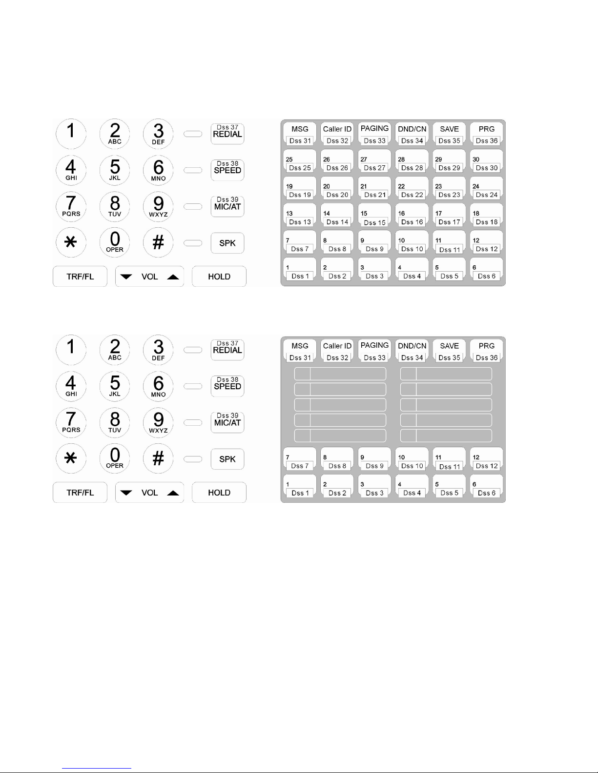
DK6 Key Telephone – Key Layout (36 Button)
DK6 Key Telephone – Key Layout (18 Button)
Page 16

Program 01-tk-IP : Day Ringing And Ringing Line Preference Assignment
01-tk-IP FLX DAY
111 000 000 000
General:
This program assigns each incoming line to ring the programmed stations during Day Service. Program Mode 35-tk-07
assigns ringing type for each trunk.The ringing methods can be:
LINEAR (ring the first available station),
CIRCULAR (Ring the next station following the last station who just answered an incoming call),
HUNT (Ring the first assigned station for a set period of time (program mode 05-08-01) then if no answer ring the next
ring assigned station then the next etc.) or
COMMON AUDIBLE (All stations will ring simultaneously).
An overflow Ring Hunt Group can be assigned to make additional stations ring after a time interval in addition to this
ring assignment. See program Mode 29-07/08.
Description:
1. This program sets Day Time ringing.
2. The station number length 2,3,4 digits will be set by system programming (Mode 05-03-06).
3. A total of 26 stations can be assigned to ring for each trunk.
4. If the location not assigned to a station, the location value is set to " 0 ".
5. To clear all entries press [REDIAL].
6. Lunch ringing is programmed in Mode 94.
tk=Trunk No. (01-12), IP=Item Pointer (01-26)
Assigned station number
Program 02-tk-IP : Night Ringing And Ringing Line Preference Assignment
02-tk-IP FLX NIG
111 000 000 000
General:
This program assigns each incoming line to ring the programmed stations during Night Service. Program Mode 35-tk08 assigns ringing type for each trunk. The ringing methods can be:
LINEAR (ring the first available station),
CIRCULAR (Ring the next station following the last station who answered an incoming call),
HUNT (Ring the first assigned station for a set period of time (program mode 05-08-01) then if no answer ring the next
ring assigned station then the next etc.) or
COMMON AUDIBLE (All stations will ring simultaneously).
An overflow Ring Hunt Group can be assigned to make additional stations ring after a time interval in addition to this
ring assignment. See program Mode 29-07/08.
Description:
1. This program sets Night Time ringing.
2. The station number length 2,3,4 digits will be set by system programming (Mode 05-03-06).
3. A total of 26 stations can be assigned to ring for each trunk.
4. If the location is to be assigned to no station, the location value is set to 0.
5. To clear all entries press [REDIAL].
6. Lunch ringing is programmed in Mode 94.
tk=Trunk No. (01-12), IP=Item Pointer (01-26)
Assigned station number
Page 17

Program 03-01-IP : Door Phone Ringing Assignment
03-01-IP Door
111 112 113 114
General:
This program assigns the Door Phone/s to ring the programmed stations.
Description:
1. To assign an ACP or digital door phone to follow Mode 03 it must be set to “d” in mode 46-st-07. Otherwise it will
ring the stations assigned in the Hunt Group allocated in mode 46-st-07
2. Twenty six stations can be assigned to ring for the door phone.
3. To clear all entries press [REDIAL].
4. Door phone ringing time is set in Mode 05-11-07.
5. Door Relay Unlock Time is set in Mode 05-12-04.
6. Door phone Ringing frequency is set in Mode 05-03-08.
IP= Item Pointer (01-26)
Assigned station number
Program 04-gp-IP : Console Operator Assignment
04-gp-IP Console
111 000 000 000
gp = Station group (01-08) IP = (Item Pointer) 01-04
Assigned station number (2 to 4 digits)
General:
This program permits the selection of the consoles in each station group. Consoles are stations that can program
System speed dials, Record system Voice messages, receive hold recalls and ring when callers dial 9/0 for the
operator. For DISA calls only the ring type is Common Audible otherwise Linear is standard
Description:
1. There are 8 console groups available. Four stations can be set in each group
2. Assign either a station or the pilot number of a hunting group as the console(s).
4. The first assigned station is the master console if a pilot number is assigned here.
5. Only the Console can operate some special Voice Mail features.
6. To clear all entries press [REDIAL]. Do this in ALL unused groups.
Page 18
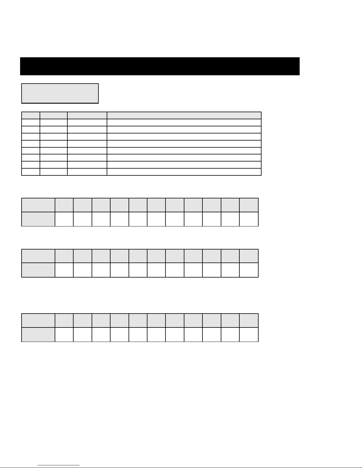
Program 05-01-IP : System Timing Parameters – 01
05-01-IP SYS PAR
1 1 1 1 4 2 2 1
IP=Item Pointer (01-08)
Value for each Item
IP Value Default Item Description
01 0-9 1= 60 sec. Hold Recall Time
02 0-9 1= 60 sec. Exclusive Hold Recall Time
03 0-9 1= 60 sec. Hold Recall Timeout
04 0-9 1= 2 sec. DISA & ECF Access Delay Time - Day
05 0-9 4= 8 sec. Busy Remind Cycle Time
06 0-9 2= 800 ms Pause Time
07 0-9 2= 83 ms DTMF Generation Time
08 0-9 1= 20 sec. Call Forward No Answer Transfer Time
01. Hold Recall Time
This parameter sets the duration from the time the line is put on Hold until the held call recalls the station.
IP \ Value 0 1 2 3 4 5 6 7 8 9 Unit
05-01-01 30 60 90 120 150 180 210 240 253 None sec.
02. Exclusive Hold Recall Time
This parameter sets the time duration from the line is put on Exclusive Hold to the held call recalls the station.
IP \ Value 0 1 2 3 4 5 6 7 8 9 Unit
05-01-02 30 60 90 120 150 180 210 240 253 None sec.
03. Hold Recall Timeout
This parameter sets the timer between a held call recalling to a holding or transferring station (i.e., 05-01-01 or 05-0102 expires) and then recalling to the console if unanswered.
IP \ Value 0 1 2 3 4 5 6 7 8 9 Unit
05-01-03 30 60 90 120 150 180 210 240 253 None sec.
Page 19

04. DISA & ECF Access Delay Time - Day
This parameter sets the timer that a DISA/ECF (External Call Forwarding) trunk will ring assigned stations (set by
Program 01-tk-IP, 02-tk-IP) prior to be connected to Auto Attendant (DISA) or another Trunk (ECF) in Day mode.
Stations can answer the incoming trunk before it is connected to Auto Attendant or another Trunk.
IP \ Value 0 1 2 3 4 5 6 7 8 9 Unit
05-01-04 0 2 4 6 8 15 30 60 120 254 sec.
Note:
0 = Incoming trunk immediately connects to Auto Attendant or another trunk without ringing assigned stations.
1-9 =Incoming trunk connects to Auto Attendant or another trunk after 2-254 seconds ringing.
Also see Program 05-11-04 for Night delay and Program 05-17-4 for Lunch delay.
05. Busy Remind Cycle Time (Off-Hook Ringing)
This parameter sets the timer an incoming trunk periodically rings a busy station. It is used to remind the busy station
that another trunk is waiting on the line. A muted, one-second ring will be given to the station through the speaker to
indicate the waiting call. The ring will be repeated at intervals defined by this busy remind cycle time.
This parameter also sets the timing for the SLT Camp-On feature (see Mode 05-08-03 SLT Camp On Time) and the
camp on tone for key stations.
IP \ Value 0 1 2 3 4 5 6 7 8 9 Unit
05-01-05 0 2 4 6 8 15 30 60 120 254 sec.
06. Pause Time
This parameter sets the system pause time duration for speed dial entry, trunk access time and voice mail call
forwarding tone delay.
IP \ Value 0 1 2 3 4 5 6 7 8 9 Unit
05-01-06 400 600 800 1000 1200 1400 1600 1800 2000 2200 ms.
07. DTMF Generation Time
This parameter sets DTMF generation time. It may need to be lengthened to access some Voice Mail or answering
machines.
IP \ Value 0 1 2 3 4 5 6 7 8 9 Unit
05-01-07 48 64 80 100 114 132 156 164 180 196 ms.
08. Call Forward No Answer Transfer Time
This parameter sets the amount of time a call is ringing a station (set Call Forward No Answer) before it is transferred
to another station.
IP \ Value 0 1 2 3 4 5 6 7 8 9 Unit
05-01-08 10 20 30 40 50 60 70 80 90 100 ms.
Page 20

Program 05-02-IP : System Timing Parameters – 02
05-02-IP SYS PAR
5 5 1 6 4 1 2 6
IP Value Default Item Description
01 0-9 5= 15 Sec. SLT Dial Tone Timeout
02 0-9 5= 15 Sec. SLT Inter-Digit Timeout
03 1-9 1= 10 Sec. Auto Redial Access Time – PSTN Lines
04 0-9 6= 1000 ms. SLT Release Signal Time
05 0-9 4= 400 ms. PSTN Lines Flash Time - Key Phone & Analog Phone
06 0-9 1= 80 ms. SLT Hold Signal Time
07 0-9 2= 240 ms. Ring On Time
08 0-9 6= 6 Sec. Ring Off Time
01. SLT Dial Tone Timeout
This parameter is for SLT (Single Line Telephone). If a key of SLT is not pressed before this assigned timer expires
when Dial Tone is given, a Busy Tone will be heard.
IP \ Value 0 1 2 3 4 5 6 7 8 9 Unit
05-02-01 0 2 4 6 8 15 30 60 120 254 Sec.
02. SLT Inter-Digit Timeout
This parameter is for SLT (Single Line Telephone). If the interval between digits dialed exceeds this assigned timer, a
Busy Tone will be given.
IP=Item Pointer (01-08)
Value for each item
IP \ Value 0 1 2 3 4 5 6 7 8 9 Unit
05-02-02 0 2 4 6 8 15 30 60 120 254 Sec.
03. Auto Redial Access Time – PSTN Lines
This parameter sets the waiting timer after system redial the telephone number in Auto Redial feature. If the call is not
answered before this timer expires, system will hang up and wait for the Auto Redial Pause Time – Program 05-0508, and then try to redial again. ISDN lines will hang up immediately if the called number is busy. Refer to Program 0505-07 Auto Redial Trials for number of redial attempts
IP \ Value 1 2 3 4 5 6 7 8 9 Unit
05-02-03 10 20 30 40 50 60 70 80 90 Sec.
04. SLT Release Signal Time
The time duration of depressing the hook switch of an SLT longer than this timer and then system will recognize it as a
Release Signal. Please note that the system will take it as a Hold signal if less than this timer but longer than the SLT
Hold Signal Timer (Program 05-02-06).
IP \ Value 0 1 2 3 4 5 6 7 8 9 Unit
Page 21
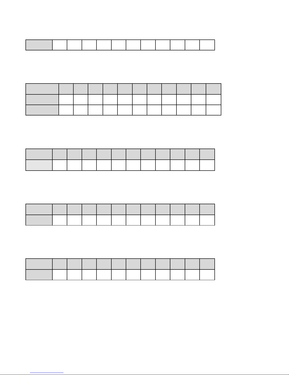
05-02-04 100 200 300 400 600 800 1000 1200 1400 1600 ms.
05. PSTN Line Flash Time - Key Phone & Analog Phone
This parameter sets the Flash timer at PSTN trunk line when Key Phones pressing the [TRF/FL] key or an analog
phone makes a flash and then dials 800 while accessing an outside line. After dialing 800 the flash signal will be sent
to the PSTN line and the analog phone will be reconnected to the PSTN line again.
IP \ Value 0 1 2 3 4 5 6 7 8 9 Unit
05-02-05 40 80 160 240 400 600 800 1000 1200 1400 ms.
UK, Italy, Aust 60 80 100 120 140 160 180 200 300 600 ms.
06. SLT Hold Signal Time
This parameter permits the selection of the Flash time from a single line telephone that the system will recognize as a
Hold signal if the time is greater than this hold signal time but less than the SLT release time (Program 05-02-04)
IP \ Value 0 1 2 3 4 5 6 7 8 9 Unit
05-02-06 70 80 100 200 300 400 500 600 700 800 ms.
07. Ring On Time
This parameter allows the system to identify a minimum ring signal time from the PSTN line. This parameter should
never be changed without a clear understanding of the operation of the feature.
IP \ Value 0 1 2 3 4 5 6 7 8 9 Unit
05-02-07 0 160 240 360 440 560 640 760 840 960 ms.
08. Ring Off Time
This parameter allows the system to identify when a ringing call has abandoned by the absence of any ring signal from
the PSTN. This parameter should never be changed without a clear understanding of the operation of the feature.
IP \ Value 0 1 2 3 4 5 6 7 8 9 Unit
05-02-08 2 2 2 3 4 5 6 7 8 9 Sec.
Page 22

Program 05-03-IP : System Timing Parameters – 03
05-03-IP SYS PAR
1 0 0 9 0 2 0 0
IP Value Default Item Description
01 0-1 1= 40/60 Make / Break Ratio
02 0-1 0= Yes Automatic Trunk Search
03 0-1 0= Voice Intercom Call Signalling Method
04 0-9 9= 9 PABX (Centrex) Outgoing Code
05 0-9 1= 1 Toll Access Code
06 2-4 2= 2 digits Station Numbering Plan
07 0-1 0= Steady Internal Dial Tone Pattern
08 0-9 0= Continuous ring Door Phone / ACP Ringing Frequency
Description:
01. Make/Break Ratio
This parameter permits the selection of a Make/Break Ratio for Dial Pulse signalling.
IP \ Value 0 1
05-03-01 33/66 40/60
02. Automatic Trunk Search
This parameter allows the system to search for an available trunk according to the assigned dial 9 trunk group when
automatic dialing features are used; i.e., Speed Dial, Save Redial, Redial, etc.
IP=Item Pointer (01-08)
Value for each Item
IP \ Value 0 1
05-03-02 Allowed Not Allowed
03. Intercom Call Signalling Method
This parameter selects the Intercom calling method. The user can still override this selection by dialing 3 after initiating
an intercom call. Individual stations can be set to automatic microphone switch-on in mode 46-st-03 and thus override
the system-wide ring method.
IP \ Value 0 1
05-03-03 Voice Signalling Ring Signalling
04. PABX (Centrex) Outgoing Code: (Refer to Program 35-TK-01)
This parameter assigns the PABX outgoing call access code for Redial and Save Redial when the system is installed
behind a PABX. It is used when Trunk Lines are set to be PABX lines in Mode 35-TK-01.
This assignment also enables the system to identify whether the user's dialing is a PABX's Intercom call or an
Outgoing call for toll restrictions. This Outgoing Code can be any one digit (0,1,2,3,4,5,6,7,8,9).
Page 23

05. Toll Access Code
It is the first dialing digit that will be checked as an effective Toll Call or not. This has no effect on toll control within the
system. It is only used to notify SMDR that a call is Toll Call or not. Refer to Program 14-01-03. Record Local Calls.
The Toll Access Code can be any one digit (0,1,2,3,4,5,6,7,8,9).
06. Station Numbering Plan
This parameter assigns the number of digits used for the station numbering plan. 2, 3, or 4 digits may be used.
IP \ Value
2 3 4
05-03-06 2 Digits 3 Digits 4 digits
07. Internal Dial Tone Pattern
System will provide different Dial tone to Analog phone when it is off hook to notifying its status. There are four
different situations which can be identified as follows:
Intercom: Normal situation without setting to DND, CFW or MW.
DND: Do Not Disturb.
CFWD: Call Forwarding
MW: Message Waiting (Some left message on the phone).
There are three different Dial Tone patterns:
Steady: Continuous Dial Tone
2-Burst: (Stutter Dial Tone): 250ms on / 250ms off / 250ms on / 1250ms off
3-Burst: 250ms on / 250ms off / 250ms on /250ms off / 250ms on / 750ms off
Notes:
1) If the parameter is set to 0 or 1 then the analog phone will receive the 2-Burst tone if call forward or DND has been
set for that extension.
2) Value 2 (and 6) is particularly designed for use when there is an external Voice Mail system connected to the
system, as some Voice mail units have problems with interrupted dial tone.
3) Value 6 will also provide what is known as Stutter dial tone to extensions when they are left a message. This is
useful where phones do not have a message light. When this is enabled as well as MW light to handsets by other
methods the phones with messages will receive both Message light and stutter dial tone.
IP
05-03-07
Value Intercom DND CFWD MW
0 Steady 3-Burst 3-Burst Steady
05-03-07 1 2-Burst 3-Burst 3-Burst 2-Burst
05-03-07 2 Steady Steady Steady Steady
05-03-07 3 2-Burst 2-Burst 2-Burst 2-Burst
05-03-07 4 Steady 3-Burst 3-Burst 2-Burst
05-03-07 5 2-Burst 3-Burst 3-Burst Steady
05-03-07 6 Steady Steady Steady 2-Burst
05-03-07 7 2-Burst 2-Burst 2-Burst Steady
08. Door Phone Ring Pattern
This parameter allows for different ring patterns when the Door Phone button is pressed. This Parameter will also
affect the ACP phone. If this mode is set to = 0 then the ACP will follow the extension ringing frequency otherwise it
will follow settings in this Mode. This allows stations that to distinguish a call from an ACP/Doorphone from other calls.
IP \ Value
0 1-8 9
05-03-08 Continuous ring Same Ringing - 1 to 8 as DK handset
Background Music
(Program 05-08-08)
Page 24
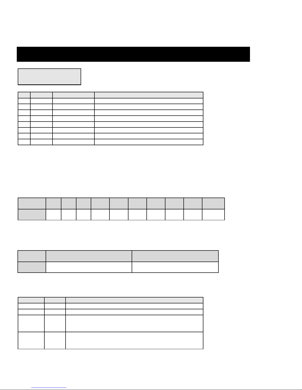
Program 05-04-IP : System Timing Parameters – 04
05-04-IP SYS PAR
4 1 0 0 0 1 0 0
IP Value Default Item Description
01 0-9 4= 9600 System Baud Rate Setting
02 0-1 1= Enable Dial 9 Flag
03 0-8 0= Warning Action for Call Duration Limiting
04 0-1 0= 12 Hours 12/24 Hours Clock
05 0-9 0= None SLT Hook flash Answer Delay
06 0-4 1= 200 Sets Speed Dialing Distribution
07 0-1 0= Disable Single Digit Intercom
08 0-4 0= 90v DC Message Waiting Method - Analog Phones
Description:
01. System Baud Rate Setting
This parameter sets the system Baud Rate of RS232 port for the following application:
1) SMDR= 9600 bps
2) SM5= 3600 bps
3) Software update = 57600 bps
4) G1E Monitor= 57600 bps (Refer to Program 05-24)
IP \ Value 0 1 2 3 4 5 6 7 8 Unit
05-04-01 1200 2400 3600 4800 9600 19200 38400 57600 115200 bps
IP=Item Pointer (01-08)
Value for each Item
02. Dial 9 Flag
This parameter sets if a station can access an outgoing line by dialing 9. If this parameter is disabled the station can
still access an outgoing line by pressing a line key on a Key phone or dial 8xx (xx is the trunk number).
IP \ Value 0 1
05-04-02 Dial 9 feature is enabled Dial 9 feature is disabled
03. Action for Call Duration Limiting
This parameter decides what action will be taken if a station has limit call duration enabled in Mode 40-nnnn-03.
Settings 0 to 3 are for outgoing calls only. The outside party will also hear the warning tone.
IP \ Value
05-04-03
05-04-03 1 & 6 1 second Warning Tone for each cycle of Limit Call Duration
05-04-03 2 & 7
05-04-03 3 & 8
Value Value Description
0 & 5 Continuous Warning Tone after Timeout
At 10 seconds before Timeout, 1 second Warning Tone
At 5 seconds before timeout, continuous Warning Tone,
At timeout the line is released.
At 1 minute before timeout, 1 second warning tone,
At 30 seconds before timeout, continuous warning tone
At timeout the line is released.
Page 25
Related System Program: 40-st-03
04. 12/24 Hours Clock
This parameter determines the clock display method on the LCD display of key phones.
IP \ Value 0 1
05-04-04 12 Hour Clock AM/PM 24 Hour Clock
05. SLT Hook Flash Answer Delay
This timer provides a guard time to prevent an SLT user from making an un-intended Hook Flash, such as lifting the
handset but dropping on hook again, when it tries to answer a call. The Hook Flash detection will be delayed this time
interval before activating.
IP \ Value 0 1 2 3 4 5 6 7 8 9 Unit
05-04-05 disable 1 2 3 4 5 6 7 8 9 sec.
06. Speed Dialing Distribution
This parameter sets the number of speed dial numbers allocated to the system or personal. The total number is 1000
sets with 100 allocated to system and 900 to personal. If name feature is enable the total number of speed dial will be
reduced to half its total. For example: if personal has 900 speed dial, when name feature is enable, its total number
will be dropped to 450. Please note that the personal speed dials are shared between all extensions. To assign the
number of personal speed for each extension refer to Mode 42-nnn-DP
IP \ Value Value Speed Dial Number Personal Total / Name Feature
05-04-06
05-04-06
05-04-06
05-04-06
05-04-06
05-04-06
05-04-06
05-04-06
05-04-06
0 100 (100 to 199)
1 200 (100 to 299)
2 300 (100 to 399)
3 400 (100 to 499)
4 500 (100 to 599)
5 600 (100 to 699)
6 700 (100 to 799)
7 800 (100 to 899)
8 900 (100 to 999)
900/450
800/400
700/350
600/300
500/250
400/200
300/150
200/100
100/50
Note: Numbers after backslash at Personal is the total available with name feature enabled.
07. Single Digit Intercom
Single digit intercom allows the stations to call up to 5 other stations by dialing one digit only (1 to 5). This feature is for
the Hotel / Motel Environment. Up to eight different groups may be programmed. If a group is not programmed with
any entries then stations which are in the same number station group will be able to make intercom calls without
dialing the room to room dialing prefix (6).
IP \ Value 0 1
05-04-07 Disable Enable
Page 26

08. SLT Message Waiting Method
IP \ Value 0 1 3
05-04-08 90V DC Ring Two 250 ms. Ring Burst
Description:
0=90V Message light
90 Volts DC will operate industry standard neon light message waiting phones.
1=Auto Ring
If the setting is Ring, the single line phone will receive 30 seconds intercom ringing every 5 minutes until the station
answers.
3=Special Ring 250 ms
If the setting is 250 ms. Ring, the single line phone will receive two 250-ms. ring burst every 5 minutes. This is for use
with the special telephones to turn on message lamp.
Page 27
Program 05-05-IP : System Timing Parameters – 05
05-05-IP SYS PAR
0 0 0 0 7 1 1 0
IP Value Default Item Description
01 0-3 0= Morning Call Type
02 0-1 0= Reserved (for Meter Pulse Detection)
03 0-5 0=0 Speed Dial Unrestricted-1
04 0-9 0=0 Speed dial Unrestricted-2
05 0-7 7=enable all Name Feature For Extensions, Trunks, Speed dials
06 0- 0= Reserved
07 0-9 1=2 Times Auto Redial Trials
08 0-9 0=10 Sec. Auto Redial Pause Time
01. Wake Up Call
This parameter is used for the Hotel/Motel manager to decide which kind of Wake-up call is used to notify guests for
wake-up service.
IP Value Value Description
05-05-01 0 Voice Prompt of Morning Call
05-05-01 1 Background Music or DND Tone
05-05-01 2 Voice Prompt of Wakeup Call + Wakeup Call History Output via SMDR Port
05-05-01 3 Background Music or DND Tone + Wakeup Call History Output via SMDR Port
IP = Item Pointer (01-08)
Value for each Item
Each station can be set by Program 44-st-08 to decide whether to hear Background Music or DND tone.
To record Voice Prompt of Wakeup call: Dial [8901],[Password (Default=1234)],[2][3][3] from the console.
02. Reserved
03, 04. Speed Dial Unrestricted - 1, 2
If 03, 04 settings are A and B, then the speed dial codes from 100 to AB0 are Not Toll Restricted. For example if the
settings are 1 and 1 then Speed dials from 100 up to 110 can be used by stations to bypass the Toll Restrictions.
Individual stations can be restricted from using this feature in Mode 45-st-07.
If 03, 04 settings are set to 0 and 0, then all speed dial codes are toll restricted if the station using the speed dial will
be restricted.
Page 28

05. Name Function
This parameter enables the naming feature for trunks, extensions and speed dials.
Features \ Values 0 1 2 3 5 7
Display Name instead of number for Extension V V V V
Directory Dial for Speed Dial V V V
Directory Dial for Extension V V
V: The feature is enabled.
Note 1: When any of the above features are enabled the total number of speed dial sets will be reduced. See
Program 05-04-06.
Note 2: For setting name for Extension/Speed dial/Trunk, Please refer to the Program 43 press [MIC]
Note 3: For setting “Directory Dial” key, Please refer to Program 07.
06. Reserved
07. Auto Redial Attempts
This parameter is to set the number of Auto Redial attempts that the system will try.
IP \ Value 0 1 2 3 4 5 6 7 8 9 Unit
05-05-07 0 2 5 9 19 29 39 49 59 69 times
08. Auto Redial Pause Time
This timer defines the length of time a system will remain on hook (between attempts) between Auto Redial attempts.
IP \ Value 0 1 2 3 4 5 6 7 8 9 Unit
05-05-08 10 20 30 40 50 60 70 80 90 100 sec.
Page 29
Program 05-06-IP : System Timing Parameters – 06
05-06-IP SYS PAR
4 4 1 1 0 3 0 0
IP Value Default Item Description
01 0-9 4=30 Sec. Transfer Busy Recall Time
02 0-9 4=30 Sec Transfer Idle Recall Time
03 0-1 1=u-law
04 0-9 1=enable Polarity Reversal
05 0-1 0=0 Operator Code
06 0-9 3=3 Min. Unsupervised Conference & ECF Time Setting
07 0-1 0=Flash Hold Method for SLT
08 0-2 0=Common Station Hunting Group Ring Method
01. Transfer Busy Recall Time
This timer defines the time duration for transferring a call to a busy party and then transfer back to the original
transferring party when the called party is busy.
IP \ Value 0 1 2 3 4 5 6 7 8 9 Unit
05-06-01 5 10 15 20 30 40 50 60 70
Note: ∞ = Infinite. It means never Recall.
IP =Item Pointer (01-08)
Value for each Item
ISDN Audio Coding (a-law orμ- law)
∞
Sec.
02. Transfer Idle Recall Time
This timer defines the time duration for transferring a call to a idle station and then transfer back to the original
transferring party when the called party does not answer.
IP \ Value 0 1 2 3 4 5 6 7 8 9 Unit
05-06-02 5 10 15 20 30 40 50 60 70
Note: ∞ = Infinite. It means never Recall.
03. ISDN Audio Coding (a-law or μ- law)
This parameter sets the ISDN Audio companding algorithm. It is not necessary to change this parameter as the
software defaults will be set for each market. North America uses μlaw.
IP \ Value 0 1
05-06-03 a-law
μ- law
∞
Sec.
Page 30

04. Polarity Reversal
This parameter is to enable the Polarity Reversal detection feature for incoming caller hang up detection in Australia
and some European countries. See Mode 14-01-08 for SMDR setting. Telecom provider needs to enable its polarity
reversal feature at the central office. When this reversal is enabled the system will hang up the CO line when the
incoming caller hangs up and the CO sends a Polarity Reversal signal to the system.
IP \ Value 0 1 2 to 9
05-06-04 Disable Enable Enable after 1 to 8 seconds delay
Note: 2-9 =Delay for 1-8 Seconds after accessing the line and then detect Polarity Reverse Signal
05. Operator Code
This parameter is to set whether to dial "0" or "9" for calling the operator or accessing a CO. line.
IP \ Value 0 1
05-06-05 Dial "0" for operator, "9" for C.O. line. Dial "9" for operator, "0" for C.O. line.
06. Unsupervised Conference & ECF Time Setting
This timer defines the allows time duration on Unsupervised Conference or ECF (External Call Forward) calls. The
system will send a warning tone prior to disconnecting the call. If either party sends a DTMF digit (0-9) to the system
the timer will reset and allow the call to continue for this time setting. If reversal supervision is used, system will
release the line when reversal signal is detected.
IP \ Value 0 1 2 3 4~9 Unit
05-06-06 No Limit 1 2 3 4 Min.
07. Hold Feature for SLT
This parameter is to set whether Single Line Telephones use [FLASH] or [FLASH, 7] to place a call on Hold.
IP \ Value 0 1
05-06-07 Normal
Use [FLASH] to place a call on Hold.
Use [FLASH, 7] to place a call on Hold.
Alternate
08. Station Hunting Group - Ring Method:
This parameter sets the ring method used in the station hunting groups. Pilot numbers for hunt groups are set in
Program 67, Day/Night ring stations are set in Program 68 & 69, Individual Hunt Group Ring type can be set in
Program 67-gp-02 and will over ride the system wide setting made here.
IP \ Value 0 1 2
05-06-08 Common Linear Circular
Page 31
Program 05-07-IP : System Timing Parameters – 07
05-07-IP SYS PAR
0 0 0 0 0 0 0 0
IP Value Default Item Description
01 0-1 0=Disable Intercom Searching
02 0-1 0=Disable Toll Override Prevention from Quick Dial
03 0-1 0=Enable Paging Alert Tone
04 0-7 0=Enable DISA Transfer To Console - No Dialing
05 0-1 0=Disable Key Phone Toll Override Prevention
06 0-9 0=Disable SMDR Digit Mask
07 0-9 0=0 sec. Guard Time for CO Line Re-accessing
08 0- 0= Reserved
01. Intercom Searching
If Enabled, when calling an internal station which is busy or does not answer, pressing [4] will call the next station
which is in the same station group as the called station. If setting is Disabled, then there will be no such searching.
IP \ Value 0 1 2 3
05-07-01 Disabled Enable when busy Enable when no answer Enable when busy or no answer
02. Toll Override Prevention from Quick Dial
To protect toll override control when a Key phone selects a trunk and quickly dials one digit to bypass the toll control.
When this parameter is set to Enabled, after selecting a trunk, the first digit dialed will be delayed one pause interval to
send to the Central Office.
IP = Item Pointer (01-08)
Value for each Item
IP \ Value 0 1
05-07-02 Disable Enable
03. Paging Alert Tone
This parameter enables/disables the paging alert tone.
IP \ Value 0 1
05-07-03 Enable page alert tone Disable page alert tone
04. DISA Recall To Console - No Dialing
If this function is activated, when a DISA call is answered but the caller does not dial any digits or station number, the
system will recall the Operator after the assigned DISA Transfer Time No Dialing (Program 05-08-07). If this function
is disabled the call will be disconnected after Transfer Time No Dialing elapses. This parameter is also used to clear
the VMU channels after 10 minutes of operation where central offices do not provide proper disconnect supervision
(CPC/CFS signal).
IP \ Value 0 1 2 3
05-07-04
Recall to
operator
No Recall to
operator
Recall to operator and
release line after 10
min.
No Recall to operator
and release line after 10
min.
Page 32

05. Key Phone Toll Override Prevention
If the setting is Disable, after accessing a line a user will be able to use a DTMF generator directly to the network
rather than the DTMF signal generated within the KSU. The result of this is that Toll restrictions can be over-ridden.
If the setting is Enable, then no audio will be sent from the handset until 3 digits are received by the KSU from the key
station dial pad preventing Toll restrictions being overridden. This parameter will be automatically disabled on any lines
which are set to Pulse Dial.
IP \ Value 0 1
05-07-05 Disable Enable
06. SMDR Digit Mask
If the setting is "0", then the full length of the telephone number will be output to the SMDR. If setting is n, only the first
n digits will be output to the SMDR.
n = 1 to 9
07. CO Line Guard Timer
This timer offers a pause time when a line is released before It can be accessed again.
IP \ Value 0 1 2 3 4 5 6 7 8 9 unit
05-07-07 0 1 2 3 4 5 6 7 8 9 sec.
08. Reserved
Page 33

Program 05-08-IP : System Timing Parameters – 08
05-08-IP SYS PAR
3 0 3 0 7 1 4 3
IP Value Default Item Description
01 0-9 3=6 seconds. Ring Hunt Time
02 0-1 0=Enable DSS Access To Other Trunk Group
03 0-9 0=disable SLT Camp On Tone
04 0-1 0=Station Group Console of DISA Transfer Group for No Answer
05 0-8 7=7 + Code SLT Programming Digit
06 0-9 3=32 Sec. DISA Transfer Time No Answer
07 0-9 4=4 Sec. DISA Transfer Time No Dialing
08 0-1 3=External MOH Music source selection
01. Ring Hunt Time
If setting is n, then when an incoming call rings the first assigned extension and that extension is busy, after n seconds
the call will ring the second of the ring assigned extensions. If the 2nd extension is busy the call will go to the 3rd
extension immediately. All stations which have been called by the ring assignment will receive off hook busy remind.
Up to 26 stations can be set in the ring group. If this setting is 0 then only the first ring assigned station will ring.
Related Program: 35-tk-07, 35-tk-08
IP \ Value 0 1 2 3 4 5 6 7 8 9 unit
05-08-01 Disable 2 4 6 8 15 30 60 120 254 sec.
02. DSS Access to Other Trunk Group
This feature enables or disables the ability of stations to use a DSS key to answer a Ringing CO line that is not in its
own group.
IP = Item Pointer (01-08)
Value for each Item
IP \ Value 0 1
05-08-02 Enable Disable
03. SLT Camp on Time
This feature enables a tone to indicate call waiting for a busy analog phone and sets the interval between tone
insertion. The interval between tones will be the Off Hook Busy Remind Interval (t) multiplied by the setting in this
parameter. Off Hook Busy Remind Time is set in Mode 05-01-05.
IP \ Value 0 1 2 3 4 5 6 7 8 9 unit
05-08-03 Disable 1 2 3 4 5 6 7 8 9 sec.
Note: Disable means no Camp on Tone.
Page 34

04. Console of DISA Transfer Group for No Answer
This parameter defines which console will be rung if an unsuccessful DISA call needs to be transferred. The called
station must be set in Program 46-st-04 to decide what transfer action will be taken.
IP \ Value 0 1
05-08-04
Console of the Called Station's group
(Program 41-st-01)
Console of the Incoming Trunk's group
(Program 36-gp)
05. SLT Programming Digit
This feature changes the programming digit used by an Analog phone to perform its programmable features. For
example call forward is normally 701: If this parameter is set to 3, then the call forward code will be changed to 301. If
the setting is 0 then the analog phones cannot do programming. If the setting is 8, the call forward code will changed
to [*][#][701]. before accessing programming or dialing any 8 codes. This will allow the use of digits 1 to 8 as the first
digits of station numbers.
IP \ Value 0 1 2 3 4 5 6 7 8
05-08-05 Disable 1xx 2xx 3xx 4xx 5xx 6xx 7xx
[*][#][7xx] for programming
[*][#][8xx] for accessing functions beginning with 8
Note:
1. 0=Disable. It means SLT has no programming capability.
2. 9=Disable and the [*][#] means Redial function.
06. DISA Transfer Time No Answer
An incoming call is answered by Auto Attendant and transferred to the called extension. If the called extension does
not answer after this time duration, a voice prompt will announce the status (no answer) of the called station or busy
immediately if the station is busy. The system will try to recall the console several times (by Program 05-11-6) then
release the call. Program 46-st-04 defines whether the call shall be transferred or not. Program 05-08-04 defines
which console shall be transferred to.
IP \ Value 0 1 2 3 4 5 6 7 8 9 unit
05-08-06 8 16 24 32 40 48 56 64 72 80 sec.
07. DISA Transfer Time - No Digits Dialed
This timer defines the waiting time after the Auto Attendant answers the call and plays the voice prompt before
transferring the call to the console if no digits are received. Do not set this timer to less than 3 seconds for normal
operation.
IP \ Value 0 1 2 3 4 5 6 7 8 9 unit
05-08-07 0 1 2 3 4 5 6 7 8 9 sec.
Page 35

08. Music Source Selection
This parameter sets the Music Source for the Internal Background Music, Music on Hold for CO line and Door phone
music-type ringing signal. (Program 05-03-09=9)
IP Value BGM MOH Door
05-08-08 0 Internal Music Internal Music Internal Music
05-08-08 1 External Music IMC IMC
05-08-08 2 Internal Music External Music External Music
05-08-08 3 External Music External Music External Music
05-08-08 4 SLT Music SLT Music SLT Music
05-08-08 5 External Music SLT Music SLT Music
05-08-08 6 Internal Music Internal Tone External Music
05-08-08 7 External Music Internal Tone External Music
05-08-08 8 Internal Music VMU music Internal Music
05-08-08 9 External Music VMU music Internal Music
Note:
1. BGM = Background music for internal extension only.
2. MOH = Music on Hold for CO line is put on hold.
3. Door = Set Door ringing as background music. (Program 05-03-08=9)
4. Internal Music Clip (Internal Music): This audio clip can be recorded by dialing [8901] [2][3][2] at console.
5. External Music Source (External Music): Refer to Installation Manual for linking to external music source.
6. SLT Music Source (SLT Music): Use special music interface at SLT port
7. Internal Tone: Double “DO” tone.
8. VMU music: Music Clip on the VMU card.
Page 36

Program 05-09-IP : System Timing Parameters – 09
05-09-IP SYS PAR
0 1 1 0 0 0 0 1
IP Value Default Item Description
01 0-1 0= Reserved
02 0-1 1=Enable Busy Console Queuing (Intercom Calls)
03 0-9 1= >80ms Clear Forward Signal (Loop Disconnect) Detection
04 0-9 0=Disable DISA Busy Tone Detection
05 0- 0= Reserved
06 0-9 0=5 Sec ACD-1 Enable Time
07 0-9 5=25 sec. ACD-1 Segment 2 Recall Time
08 0-9 1=5 min ACD-1 Release Time
02. Console Queuing
This feature enables the busy console(s) to have an intercom call(s) queued to it(them). If the station dials the operator
(by 0 or 9) and all the consoles are busy, the system will put this call in the queue to wait for the operators to be free.
The calling station will hear ring back tone instead of busy tone and the first operator in the group will receive the Busy
Remind Signal. The first operator to go on-hook will receive the call.
IP \ Value 0 1
05-09-02 Disable Enable
03. Clear Forward Signal (Loop Disconnect) Detection
Clear Forward Signal (CFS), also known as Calling Party Control (CPC) is a signal sent in the forward direction to
terminate a call (or call attempt) so that the associated circuits can be released. This signal is normally originated
when the calling party hangs-up the phone.
Some Central Offices provide this kind of signal by breaking (disconnecting) the Loop circuit for a period of time and
then making (connecting) again. This Break time period is varied at different CO line and some CO lines do not offer
this feature.
The parameter in this mode is the minimum Break time for formal Clear Forward Signal, so that phone system can
release the line back to idle status.
IP = Item Pointer (01-08)
Value for each Item
IP Value Value Description
05-09-03 0 No need to detect Clear Forward Signal
05-09-03
05-09-03
05-09-03
05-09-03
05-09-03
05-09-03 6 Break Time over 480 ms will recognize a formal CFS.
05-09-03
05-09-03
05-09-03
1 Break Time over 80 ms will recognize a formal CFS.
2 Break Time over 160 ms will recognize a formal CFS.
3 Break Time over 240 ms will recognize a formal CFS.
4 Break Time over 320 ms will recognize a formal CFS.
5 Break Time over 400 ms will recognize a formal CFS.
7 Break Time over 560 ms will recognize a formal CFS.
8 Break Time over 640 ms will recognize a formal CFS.
9 Break Time over 720 ms will recognize a formal CFS.
Page 37

04. DISA Busy Tone Detection
This setting allows system to recognize busy tone from the central office line during DISA call to release the call.
IP Value Value description
05-09-04 0 Disable
05-09-04 1 Australia: (420 Hz, 375ms on/off) (400 Hz, 375ms on/off)
05-09-04 2 Italian: (420 Hz, 500ms on/off)
05-09-04 3 Mexico: (420 Hz, 250ms on/off)
05-09-04 4 South African: (400 Hz, 500ms on/off)
05-09-04 5 Span: 420 Hz, 200ms on/off)
05-09-04 6 New Zealand: (400Hz, 250ms on/off)
05-09-04 7 U.S: (480 Hz + 620 Hz, 250ms on/off and 500ms on/off)
05-09-04 8 Indonesia: (500hz, 250ms on/off, 500ms on/off)
(420hz, 250ms on/off, 500ms on/off) (1000hz, Continuous on)
05-09-04 9 Israel: (450-470Hz, 700 ms on/off)
05-09-04 d Pakistan: (450Hz, on:240+-40ms off:340+-40ms)
05. Reserved
06. ACD-1 Enable Time
This parameter is to set the time duration before the system answers an incoming call when the ring assigned
station(s) are busy if the operator overflow feature is enabled. The incoming call will show as a normal ring signal on
the DSS key and can be answered by the operator at any time even while the voice message is playing to the caller.
Operator Overflow (ACD-1) is enabled in Program 29-tk-02.
IP \ Value 0 1 2 3 4 5 6 7 8 9 unit
05-09-06 5 10 15 20 25 30 35 40 45 50 Sec.
07. ACD-1 Segment 2 Recall Time
This parameter sets the time an ACD-1 call which has been answered by the Overflow message will stay on hold in
the ring queue before the system will play the second part of the ACD-1 message to apologize for the continuing delay.
The call back time for the second message starts at 5 seconds and increases in 5 second increments. The message
will be played to the caller every time the recall time is reached until answered by the operator or the caller hangs up.
IP \ Value 0 1 2 3 4 5 6 7 8 9 unit
05-09-07 Disable 5 10 15 20 25 30 40 50 60 Sec.
08. ACD-1 Release Time
This parameter sets the time at which the system will release the incoming caller during ACD-1 operation when it has
not been answered by an operator. The system will play a warning message to the caller before releasing the call. If
polarity reversal is used for incoming call clear down then this parameter should be disabled.
IP \ Value 0 1 2 3 4 5 6 7 8 9 unit
05-09-08 0 5 10 15 20 25 30 35 40 45 Mins
Page 38

Program 05-10-IP : System Timing Parameters – 10
05-10-IP SYS PAR
d d d d d d d d
IP Value Default Item Description
01 0-9,*,#,p,d d= No Digit Leading Digit 1 For Voice Mail Forwarding
02 0-9,*,#,p,d d= No Digit Leading Digit 2 For Voice Mail Forwarding
03 0-9,*,#,p,d d= No Digit Leading Digit 3 For Voice Mail Forwarding
04 0-9,*,#,p,d d= No Digit Leading Digit 4 For Voice Mail Forwarding
05 0-9,*,#,p,d d= No Digit Leading Digit 5 For Voice Mail Forwarding
06 0-9,*,#,p,d d= No Digit Leading Digit 6 For Voice Mail Forwarding
07 0-9,*,#,p,d d= No Digit Leading Digit 7 For Voice Mail Forwarding
08 0-9,*,#,p,d d= No Digit Leading Digit 8 For Voice Mail Forwarding
Description:
This parameter allows the system to insert digits before the call forwarded station number when the call forward is
received by the voice mail port if Standard Protocol is selected. If the station numbering is only 2 or 3 digits the system
will insert additional digits if the Voice Mail requires more. The last digits of the voice mail box number will still have to
be the same as the station numbering for correct recognition. The HOLD key can be used to insert a pause in the
DTMF tone sending and will display as a (p). The DND key is no digits sent and is shown as (d).
The possible value for each leading digit is 0 to 9, *, #, Pause (enter by pressing HOLD key) and No Digit (enter by
pressing DND key)
Example:
The system is set to 2 digit numbering but the voice mail requires 4 digits. The voice mail also requires a pause
between answering the call and the tones being sent. Set this parameter to the following
IP =Item Pointer (01-08)
Value for each Item
05-10-IP SYS PAR
p 1 1 d d d d d
When the call forwarded station 34 is answered by the voice mail port after the pause time the digits 1134 will be sent
to the port by the system. If station 34's voice mail box is 1134 then the mailbox number 1134 will be automatically
opened by the tones.
There are 2 different Voice Mail Protocols available in the TRANSTEL series depending on the setting in Mode 05-12-
05. If this mode is set to 0 then the Protocol will be the leading digits entered in this Mode plus the Station Number of
the forwarded station. If Mode 05-12-05 is set to 1 then the Enhanced Protocol shown on the following page will be
used.
Enhanced Protocol
Voice Mail System Leading Digit Format
1+ extension number = CFWD All Calls
2+ extension number = CFWD Busy
3+ extension number = CFWD No Answer
4+ extension number = Direct Call to Voice Mail (Station)
5+ extension number = Call Record
6+ extension number = Recall to Voice Mail
7+ CO trunk number = Incoming CO Call
Page 39
Program 05-11-IP : System Timing Parameters – 11
05-11-IP SYS PAR
0 0 1 0 0 2 5 0
IP Value Default Item Description
01 0-4 0=None DTMF Caller ID Leading Digit
02 0-1 0=1 DISA Password – 1 / 50 Sets
03 0-2 1=MOH Select Music on Hold or Ring Back Tone
04 0-1 0=0 DISA & ECF Access Delay Time - Night
05 0-3 0=[8],[9],[*],[#] DISA Special Function Access
06 0-9 2=4 Times DISA Re-check Times To Busy Console
07 0-9 5=30 Sec. Door Phone Ringing Time
08 0-8 0=Disable DISA Single Digit Dialing
01. DTMF Caller ID Leading Digit
This parameter defines the start digit of DTMF caller ID signal. The system will omit the start digit for CLI (Caller ID)
data on the display phone and CLI list. Not used in North America.
02. Number of DISA Passwords
This parameter defines the total number of DISA passwords.
At the default setting of 0 the DISA password will be set in mode 13-02. If the parameter is set to 1, there are 50
passwords available to use and they are same as the forced account codes numbers (50-99). Refer to Program: 17
Forced Account Codes.
IP \ Value 0 1
IP =Item Pointer (01-08)
Value for each Item
05-11-02 1 Password 50 Passwords
03. Select Music on Hold or Ring Back Tone
This parameter selects what the incoming caller will hear during Ring Transfer and Hold Recall conditions. The feature
is designed to prevent the caller incorrectly recognizing the International Ring Back Tone as a disconnect or busy
signal and hanging up even though their call is still in progress.
IP \ Value 0 1 2
05-11-03 Ring Back Tone Music On Hold Silence
04. DISA & ECF Access Delay Time – Night
This parameter sets the timer that a DISA/ECF (External Call Forwarding) trunk will ring assigned stations (set by
Program 01-tk-IP, 02-tk-IP) prior to being connected to Auto Attendant (DISA) or another Trunk (ECF) in Night mode.
Stations can answer the incoming trunk before it is connected to Auto Attendant or another Trunk.
IP \ Value 0 1 2 3 4 5 6 7 8 9 Unit
05-11-04 0 2 4 6 8 15 30 60 120 254 sec.
Note: 0 = Incoming trunk connects to Auto Attendant or another trunk without ring those assigned stations.
1-9 =Incoming trunk connects to Auto Attendant or another trunk after 2-254 seconds ringing.
Also see Program 05-01-04 for Day and Program 05-17-4 for Lunch delay.
Page 40

05: DISA Special Function Access
This parameter defines which system functions are able to be accessed by external DISA callers.
IP Value Value description
05-11-05 0
05-11-05 1
05-11-05 2
05-11-05 3
DISA caller can access an outside line by [9] + Password.
DISA caller can access mail box or VM from external call by [#]
DISA caller cannot access an outside line by [9] + Password.
DISA caller can access mail box or VM from external call by [#]
DISA caller can access an outside line by [9] + Password.
DISA caller cannot access mail box or VM from external call by [#]
DISA caller cannot access an outside line by [9] + Password
DISA cannot access mail box or VM from external call by [#]
Note:
1. The password for DISA caller to make another outside call is assigned at Program 13-02
2. Remote Access to retrieve messages outside the telephone system is assigned here.
3. The same applies for the system administrator who also may access the voice mail system remotely to change
greetings and service settings.
06. DISA Re-check Times To Station/Console
This function sets the number of times that an unsuccessful DISA call will attempt to recall a station and or transfer to
a console after the ringing time set in Mode 05-08-06 and depending on the setting for individual stations in Program
46-st-04. If polarity reversal or Clear Forward is available and enabled, set this parameter to 9 and the call will continue
to retry until the caller hangs up.
IP \ Value 0 1 2 3 4 5 6 7 8 9 unit
05-11-06 2 3 4 5 6 7 8 9 10 Infinite times
07. Door Phone Ringing Time
This timer sets the time duration that Door Phone Ring Assignment Stations will ring after Bell button of Door Phone is
pressed.
IP \ Value 0 1 2 3 4 5 6 7 8 9 unit
05-11-07 5 10 15 20 25 30 35 40 45 50 sec.
08. DISA Single Digit Dialing
This feature allows a DISA caller to dial stations by 1 digit (1-8) using the Hunt Groups (01-08) settings in Program
67(Pilot No. Ring), 68 (Day), and 69 (Night / Lunch). Program 05-16-03 to set second level menu for DISA Single Digit
Dialing.
IP \ Value 0 1 2 3 4 5 6 7
Enable
Noon &
Night & Day
05-11-08 Disable
Enable
Day
Enable
Night
Enable
Day & Night
Enable
Noon
Enable
Noon & Day
Enable
Noon & Night
Page 41

Program 05-12-IP : System Timing Parameters – 12
05-12-IP SYS PAR
0 0 0 2 7 0 0 0
IP Value Default Item Description
01 0-1 0=Key Phone Call Transfer Method – Key Telephone
02 0- 0= Reserved
03 0-1 0=Yes Exclusive hold capability
04 0-9 2=3 Sec. Door Unlock Relay Activation Time
05 0-7 7=Enhanced Voice Mail Call Forward Protocol Type / mute digits
06 0-1 0=Linear Linear/Circular Trunk group access
07 0-9 0=Disable LED indication of Check in / Check out on DSS console
08 0- 0= Reserved
01. Call Transfer Method – Key Telephone
This parameter allows DK phone to transfer the call by normal Analog way. That is [Hold] [Station Number] [Hang up].
Normal DK phone way to transfer a call is pressing [Hold], then dial [Station Number], pressing [TRF] key.
It also adds the ability to transfer a trunk call to another trunk (External Call Transfer) using the Transfer key rather
than the Unsupervised Conference facility.
IP Value Value Description
05-12-01 0 TRF
05-12-01
05-12-01
05-12-01
Note:
1. DK phone can transfer a trunk to another trunk by [Hold] [DSS trunk] [TRF].
2. Use [Hold] [DSS] [Hang Up] to transfer normal call and transfer trunk-to-trunk as mentioned in Note 1 above.
1 Hang Up
2 Note 1
3 Note 2
IP = Item Pointer ( 01-08 )
Value for each Item
02. Reserved
03. Exclusive Hold Capability
If this parameter is enabled all stations can use the Exclusive Hold Function. If the parameter is disabled no stations
will be able to place calls on Exclusive hold.
IP \ Value 0 1
05-12-03 Enabled Disabled
04. Door Relay Activation Time
The parameter sets the time that the door relay will remain activated after the Door Unlock function is activated by the
user. The Door unlock relay is set in Program 06.
Page 42

IP \ Value 0 1 2 3 4 5 6 7 8 9 unit
05-12-04 1 2 3 4 5 6 7 8 9 10 sec.
05. Voice Mail Call Forward Protocol Selection and Muting Leading Digits
This parameter selects between Standard Voice Mail Call Forward Protocol and the Enhanced Protocol. For a full
description of Voice Mail Protocol see Program 05-10.It will also set the muting of the leading digits
Setting Value
VMS Leading Digit Type
Mute Leading Digit
Leading Digit for VMS
0 1 2 3 4 5 6 7
Short Long Short Long Short Long Short Long
No No Yes Yes No No Yes Yes
No Yes No Yes No No Yes No
“Short” type: Use the Leading Digit programmed in program 05-10.
“Long” type: Use 10 Leading Digits. Refer to Mode 05-10 (Enhanced Protocol)
“Mute Leading Digit”: The caller will not hear the DTMF signal during the transmission of leading digits.
“ Leading Digits for VMS”:
Yes: When incoming caller call the voice mail directly, the system will send the Leading digits
(7+ CO trunk number)
No: When incoming caller call the voice mail directly, the system will not send any leading digits.
Note: Refer to Mode 05-10 for the leading digits as follow:
Voice Mail System Leading Digit Format (TCI version only)
1+ extension number = CFWD All Calls (Replaces 11 and 21eeeexxxx)
2+ extension number = CFWD Busy (Replaces 12 and 22eeeexxxx)
3+ extension number = CFWD No Answer (Replaces 13 and 23eeeexxxx)
4+ extension number = Direct Call to Voice Mail (Station) (Replaces 14eeeexxxx)
5+ extension number = Call Record (Replaces 15eeeexxxx)
6+ extension number = Recall to Voice Mail (Replaces 25eeeexxxx)
7+ CO trunk number = Incoming CO Call (Replaces 2400tt00tt)
Related System Programming Mode: 05-10, 43-cn-03, 50-ST-05
06. Linear / Circular Trunk Group Access
If this parameter is set to 0 then line selection will be the first available trunk in the users dial (9-0) group. If the
parameter is set to 1 then the lines will be selected in a Circular fashion till all lines have been used and then the
selection will start again. Do NOT use Circular with PSTN lines unless there is a very good reason as call collision will
result. Trunk Groups are programmed in Mode 36-gp.
IP \ Value 0 1
05-12-06 Linear Circular
Page 43
07. LED Indication of Check In / Check Out
This parameter disables or enables the LED indication for Check in/Check out features for the DSS consoles and DSS
Keys of DK phones.
IP \ Value 0 1
05-12-07 Disable Enable
The LED indications are as follows:
LED Description
Red and slow flash If the Reception has checked out an extension, the LED for extension will slow flash red.
When the checked out extension’s room has been cleaned by the cleaner (maid), they
Green
can dial [776] from the phone and hang up. The LED for that extension will go Green.
This means the room is ready for a new guest.
Red The room is checked in and the phone is in use.
Off The room is checked in and the phone is in idle status.
08. Reserved
Page 44
Program 05-13-IP : System Timing Parameters – 13
05-13-IP SYS PAR
1 0 0 0 5 0 6 7
IP Value Default Item Description
01 0-1 1=Enable Intercom Hot Key Dialing
02 0-1 0=Disable Immediate SMDR output
03 0-1 0=52 Sets Caller ID Buffer Block Size
04 0-9 0= Reserved
05 0,1,5 5=Name/Num CLI Record Storing Method for LCD Phones
06 0-1 0= Disable CTI-Trunk Status Report
07 0-7 6= Saturday Least Cost Routing( LCR) – Weekly Holiday 1
08 0-7 7= Sunday Least Cost Routing(LCR) – Weekly Holiday 2
01. Intercom Hot Key Dialing
This parameter when enabled allows stations to dial a call On Hook without having to lift the handset or press the
[SPK] key.
IP \ Value 0 1
05-13-01 Disable Enable
02. Immediate SMDR Output
This parameter enables system to send out SMDR record when call is made or digit is dial out. In normal case, the
SMDR record is only available when the call is completed. This feature allows external software to know who is dialing
out with which digits or who is ringing into the system without waiting until the call is completed. The external software
can then start to count the cost from the beginning of the call. If the credit is 1 hour and time is expired, the external
software could release the connection by sending commands back to the KSU.
IP = Item Pointer (01-08)
Value for each Item
IP \ Value 0 1
05-13-02 Disable Enable
02. Caller ID Buffer Block Size
This parameter sets the memory block size of Caller ID buffer:
IP Value Memory Block Size Total Memory blocks
05-13-03 0 10 sets 52
05-13-03 1 20 sets 26
05-13-03 2 30 sets 17
05-13-03 3 40 sets 13
Refer to Program 83 to allocate the blocks for each DK phone.
Page 45

04. Reserved
05. Caller ID Record Storing Method for LCD Phones
This parameter defines which information shall be stored into the Caller ID buffer in the DK phone.
IP \ Value Value Value Description
05-13-05 0 Store Caller ID telephone numbers.
05-13-05
05-13-05
1 Store Caller ID names
5 Store Caller ID telephone number and name.
If mode 05-13-05 = 1, pressing [CLI History] key, system will display CLI number and name. Pressing [MIC/AT] will
display the date/time the call took place.
06. CTI-Trunk Status Report
Enabling this parameter will output the trunk status report for CTI applications.
IP \ Value 0 1 4 5
05-13-06 Disable Enable Enable Extension Status Report Enable Trunk Status report
07. Least Cost Routing – Weekly Holiday 1
This parameter set the first weekly holiday for Least Cost Routing feature. This generally refers to Saturday.
IP \ Value 0 1 2 3 4 5 6 7
05-13-07 No weekly holiday Monday Tuesday Wednesday Thursday Friday Saturday Sunday
Related system Programming: 05-13-07. 05-13-08, 75, 76, 77, 78-st-01, 78-st-02
08. Least Cost Routing – Weekly Holiday 2
This parameter set the second weekly holiday for Least Cost Routing feature. This generally refers to Sunday.
IP \ Value 0 1 2 3 4 5 6 7
05-13-08 No weekly holiday Monday Tuesday Wednesday Thursday Friday Saturday Sunday
Related system programming: 05-13-07. 05-13-08, 75, 76, 77, 78-st-01, 78-st-02
Page 46

Program 05-14-IP : System Timing Parameters – 14
05-14-IP SYS PAR
0 0 0 0 0 6 0 0
IP Value Default Item Description
01 0-1 0=Disable SLT LCR Switch on Delay for PSTN
02 0- 0 = Reserved
03 0- 0= Reserved
04 0- 0= Reserved
05 0- 0=Disable DISA DTMF Detect Delay Time
06 0-1 6=6 Sec. CLI Delay Ring Time
07 0- 0= Reserved
08 0- 0= Reserved
01. SLT LCR Switch on Delay for PSTN
This parameter delays the connection of SLT phones to PSTN (Public Switch Telephone Network) lines when LCR is
in use to prevent the SLT dialing from conflicting with LCR dialing.
IP \ Value 0 1 4
05-14-01 Disable 3 seconds delay 6 seconds delay
02. Reserved
03. Reserved
IP = Item Pointer (01-08)
Value for each Item
04. Reserved
05. DISA DTMF Detect Delay Time
This parameter defines the time delay for detecting DTMF signal on a DISA call after DISA answers.
IP \ Value 0 1 2 3 4 5 6 7 8 9 unit
05-14-05 0 1 2 3 4 5 6 7 8 9 sec.
06. CLI Delay Ring Time
This parameter delays the DISA transfer to ensure that CLI (Caller ID) information is available and can be sent to the
ringing station with the transferred call. If Program 05-17-07 CLI Call Screening is enabled, it will not be functional
unless this parameter is enabled.
IP \ Value 0 1 2 3 4 5 6 7 8 9 unit
05-14-06 Disable 1 2 3 4 5 6 7 8 9 sec.
07. Reserved
08. Reserved
Page 47

Program 05-15-IP : System Timing Parameters – 15
05-15-IP SYS PAR
0 0 0 0 0 0 0 0
IP Value Default Item Description
01 0-7 0= Company Greeting Time
02 0-1 0=3.1K ISDN FAX protocol
03 0- 0= Reserved
04 0- 0= Reserved
05 1- 2= Reserved
06 1- 0= Reserved
07 0- 0= Reserved
08 0- 0= Reserved
Description:
01. Company Greeting Time
This parameter extends the company greeting (60 seconds) of Auto Attendant by adding the department greeting (60
seconds). Both greetings shall be recorded separately. The system will bundle them together and make a seamless
voice message.
IP 0 4
05-15-01
02. ISDN FAX protocol
This parameter is made for ISDN BRI/PRI interface only.
When the SLT has a FAX machine installed and it wants to transmit and receive FAX signals through an ISDN trunk
line, the ISDN trunk will send the 3.1K ISDN protocol to notify the Central Office that a FAX signal will go through it.
Please note that key phone won’t send FAX signal, ISDN trunk will send Speech protocol as always when key phone
accesses it. So, this parameter only affects telephone devices that are installed on SLT ports when they access the
ISDN trunk line.
Company Greeting
IP = Item Pointer ( 01-08)
Value for each Item
= 60 seconds
Company + Department Greeting
= 120 seconds
IP 0 1
02
ISDN trunk sends 3.1K protocol
when SLT accesses it.
ISDN trunk always sends Speech protocol
when SLT accesses it.
Page 48

03. Reserved
04. Reserved
05. Reserved
06. Reserved
07. Reserved
08. Reserved
Page 49

Program 05-16-IP : System Timing Parameters – 16
05-16-IP SYS PAR
0 0 0 0 0 0 0 0
IP Value Default Item Description
01 0-1 0=Disable Midnight Reset
02 0-1 0= Reserved
03 0-8 0=One Level DISA Single Digit Dialing Level
04 0-8 0=Disable VMU language Service
05 0-9 0= Reserved
06 0-1 0= Reserved
07 0-3 0= CTI ACP Data Output Format
08 0-3 0= Reserved
01. Midnight Reset
When this parameter is set to enable, system will restart the system at midnight and clear all Ram data. If set to 2,
system will also force all VM channels to be cleared
IP \ Value 0 1 2
05-16-01 Disable Enable Enable & Clear all VM channels.
02. Reserved
03. DISA Single Digit Dialing Level
IP = Item Pointer (01-08)
Value for each Item
IP Value Value Description
05-16-03 0
05-16-03 1
05-16-03 2
05-16-03 n
05-16-03 8
One level. System plays VMU standard greeting after DISA answers the incoming call. Users
can dial either the extension number or the single digit service.
Two levels. When incoming call rings in to the system, the external party will hear the
“Company Greeting to announce “Press 1 to access different department by single digit
service”.
Two levels. When incoming call rings in to the system, the external party will hear the
“Company Greeting to announce “Press 2 to access different department by single digit
service”.
Two levels. When incoming call rings in to the system, the external party will hear the
“Company Greeting to announce “Press n to access different department by single digit
service”.
Two levels. When incoming call rings in to the system, the external party will hear the
“Company Greeting to announce “Press 8 to access different department by single digit
service”.
Page 50
04. VMU Language Service
This parameter enables two language services for VMU.
IP Value Value Description
05-16-04 0 Feature is disabled
05-16-04 1 Press 1 to select second language service.
05-16-04 2 Press 2 to select second language service.
05-16-04 ….
…………….
05-16-04 8 Press 8 to select second language service.
05-16-04 9 Play 1st Language then play 2nd Language service.
05. Reserved
06. Reserved
07. ACP Data Output Format
This parameter chooses the output format of ACP data. The format can be plain text or CTI format.
IP value Value Description
05-16-07 0 CTI format output to RS232.
05-16-07
05-16-07
05-16-07
1 ACP access data will be stored in system. (800 max. records)
2 CTI format output to RS232.
3 Text format output to RS232.
08. Reserved
Page 51

Program 05-17-IP : System Timing Parameters – 17
05-17-IP SYS PAR
0 1 0 0 0 0 0 0
IP Value Default Item Description
01 0-1 0= Reserved
02 0-1 1=32k Voice Compression
03 0-1 0=No Extension Number Announcement for DISA
04 0-8 0=0 DISA & ECF Access Delay Time – Lunch
05 0-9 0=None DTMF Caller IDI Leading Digits
06 0-1 0=None DTMF Caller ID Trailing Digits
07 0-2 0= No CID Call Block or Transfer to Voicemail
08 0-9 5=5 Seconds Minimum Mailbox Record Time
Description:
01. Reserved
02. Voice Compression
The default setting for the 256Mb VMU can be 32K or 16K bps compression rate. For customers who want to increase
the recording capacity this parameter allows the compression rate to be 16 KBPS. This doubles the available amount
of storage time on the VMU while voice quality will be decreased.
IP \ Value 0 1
IP = Item Pointer (01-08)
Value for each Item
05-17-02 16K bps 32K bps
03. Extension Number Announcement for DISA
The Auto Attendant has two ways of announcement for transferring the call. The stanadard announcement is “Please
hold while I transfer the call.” Optional announcement is “ xxx, Please hold while I transfer the call”. The xxx is the
extension number being transferred to. After the above announcement, the system will send Ring-Back tone to
external calling party.
IP \ Value 0 1
05-17-03 “ Please hold while I transfer the call” “ xxx, Please hold while I transfer the call”
04. DISA & ECF Access Delay Time – Lunch
This parameter sets the timer that a DISA/ECF (External Call Forwarding) trunk will ring assigned stations (set by
Program 01-tk-IP, 02-tk-IP) prior to being connected to Auto Attendant (DISA) or another Trunk (ECF) in Lunch mode.
Stations can answer the incoming trunk before it is connected to the Auto Attendant or another Trunk.
IP \ Value 0 1 2 3 4 5 6 7 8 9 Unit
05-17-04 0 2 4 6 8 15 30 60 120 254 sec.
Note: 0 = Incoming trunk connects to Auto Attendant or another trunk without ringing assigned stations.
1-9 =Incoming trunk connects to Auto Attendant or another trunk after 2-254 seconds ringing.
Also see Program 05-01-04 for Day and Program 05-11-4 for Night mode.
Page 52

05. DTMF Caller ID Leading Digits
This parameter enables/disables the display of leading digits on DTMF Call ID
IP \ Value 0 1 2 3 4 5 6 7
05-17-05
No
code
A B C D * # Note 1
Note:
1. Only display normal digits (0,1,2,.., 9)
2. Example: D0289661356C
Leading code =D
Trailing code = C
06. DTMF CLI Trailing Digits
This parameter enables/disables the display of Trailing digits on DTMF Call ID
IP \ Value 0 1 2 3 4 5 6 7
05-17-05
No
code
A B C D * # Note 1
Note:
3. Only display normal digits (0,1,2,.., 9)
4. Example: D0289661356C
Leading code =D
Trailing code = C
07. Call Block or Transfer to Voice Mail according to Caller ID Message
This parameter allows the system to reject or send the call to a virtual Voicemail based on the CLI received. When a
call is rejected the DSS LED for the line is flashing but there will be no audible ring. CLI numbers to be screened must
be specified in Mode 09 system speed dial.
Mode 05-14-06 and 05-05-05 must also be enabled to make this feature happen.
Call blocking by CLI is to screen out unwanted callers. There are four different call blocking situations as follows:
Mode 05-17-07=0
There is no call blocking feature
Mode 05-17-07=1
If there is no CLI information from the incoming call, the LED of that CO line DSS key will be flashing, but no ringing
signal to alert the operator.
If there is CLI information from the incoming call and the CLI is matching with the call blocking number that is assigned
at Mode 09, the LED of that CO line DSS key will be flashing, but no ringing signal to alert the operator.
Mode 05-17-07=2
If there is no CLI information from the incoming call, the call will be transferred to the virtual voice mail -41.
If there is CLI information and the CLI is matching with the call blocking number that is assigned at Mode 09, the call
will be transferred to the virtual voice mail – 41 or 42 or 43 or 40 that is LED flashing without ring.
Note
1) If the VMC is not installed, the call will not be transferred to the virtual mail -41. And the LED of that CO line DSS
key will be flashing, but no ringing signal to alert the operator.
Mode 05-17-07=4
If there is no CLI information from the incoming call, there is no call blocking feature, the call will be ringing normally
with LED flashing.
If there is CLI information and the CLI is matching with the call blocking number that is assigned at Mode 09, the call
will be blocked. (LED of that CO line DSS key will be flashing, but no ringing signal to alert the operator)
Page 53

Associated program modes 09, 05-05-05, 05-14-06, 43-51-05, 43-52-05, 43-53-05
08. Minimum Mail Box Record Time
Some callers will after hearing a personal greeting and then the Beep hang up after a short period. This will then leave
a short message usually of silence followed by the sound of a handset being replaced. This parameter will allow
messages that do not reach a certain length to be deleted.
IP \ Value 0 1 2 3 4 5 6 7 8 9 unit
05-17-08 Disable 1 2 3 4 5 6 7 8 9 sec.
Page 54

Program 05-18-IP : System Timing Parameters – 18
05-18-IP SYS PAR
0 0 0 0 0 0 8 5
IP Value Default Item Description
01 0- 0= Reserved
02 0- 0= Hotel Alarm
03 0-1 0=Disable Dial out History Feature
04 0-1 0=Bellcore/ETSI Caller ID Compatibility
05 0- 0= Reserved
06 0- 0= Play Transfer message for ECF
07 0-9 0= High Frequency Level of DTMF Generator
08 0-9 0= Low Frequency Level of DTMF Generator
01. Reserved
02. Hotel Alarm
This feature is designed for the Hotel environment but also could be used in other situations.
When the user presses an emergency button that provides a short circuit on the pair of an SLT extension line this will
trigger an Alarm Ring signal to the console with the LCD message as follow:
Extension: xx
Shower Alarm
If a user lifts the handset to make an emergency call, but is unable to speak for some reason, after 2 minutes, the
console will receive an Alarm Ring with the LCD message as follows:
IP = Item Pointer (01-08)
Value for each Item
Extension: xx
Handset Alarm
IP \ Value 0 1
05-18-02 Disable this feature Enable this feature
Note:
Extensions that need this feature should be enabled in mode: 50-STN-08: Hotel Alarm.
03. Dial Out History Feature
This parameter enables a dial out history memory buffer. When this feature is enabled the user can press [Redial] and
using the [Up/down] volume keys, scroll through the last 10 dialed out numbers and then pressing the [SPK] key to dial
out the numbers.
IP \ Value 0 1
05-18-03 Disable Enable
Page 55

04. Caller ID Compatibility (Canada)
Most telco central offices have adopted the Bellcore/ETSI standard for MDMF (Name and Number) Caller ID.
However, there are some central offices in Canada which still utilize an obsolete Canadian only standard called
Stentor. This parameter alters the Caller ID reception to support Stentor.
IP \ Value 0 1
05-18-04 Bellcore/ETSI Stentor
05. Reserved
06. Play Transfer message for ECF
This parameter enables the ECF (External Call Forwarding) voice announcement to an incoming caller when they are
being transferred to an external telephone number by the system
IP \ Value 0 1
05-18-06 Disable Enable
07. High Frequency Level of DTMF Generator
This parameter modifies the level of the High frequency DTMF Generator.
This should not be modified under any circumstances.
IP \ Value 0 1 2 3 4 5 6 7 8 9 unit
05-18-07 -16.8 -2+ -14.8 -13.4 -12.4 -11.4 -10.2 -9 -8.8 -7.8 dBm
08. Low Frequency Level of DTMF Generator
This parameter modifies the level of the low frequency DTMF Generator.
This should not be modified under any circumstances.
IP \ Value 0 1 2 3 4 5 6 7 8 9 unit
05-18-08 -16.8 -2+ -14.8 -13.4 -12.4 -11.4 -10.2 -9 -8.8 -7.8 dBm
Page 56
Program 05-19-IP : System Timing Parameters – 19
05-19-IP SYS PAR
0 0 0 0 0 0 0 0
IP Value Default Item Description
01 0- 0= Reserved
02 0- 0= Reserved
03 0- 0= Reserved
04 0-9 0=Disable VMU Silence Detection
05 0- 0=Australia Distinctive Ring Selection Australia or New Zealand
06 0- 0= Reserved
07 0- 0= Reserved
08 0- 0= Reserved
01. Reserved
02. Reserved
03. Reserved
04. VMU Silence Detection
This parameter enables Silence detection for the Voice Mail to disconnect a call after receiving this period of silence
from the caller.
IP \ Value 0 1 2 3 4 5 6 7 8 9 unit
IP = Item Pointer (01-08)
Value for each Item
05-19-04 Disable 10 20 30 40 50 60 70 80 90 sec.
05. Reserved
06. Reserved
07. Reserved
08. Reserved
Page 57
Program 05-20-IP : System Timing Parameters – 20
05-20-IP SYS PAR
0 0 0 0 0 0 0 0
IP Value Default Item Description
01 0-1 0= Disable VMU Mailbox Delete All Messages (g1-A52x)
02 0-6 0= DISA No Digits Dialed Destination (g1-A52yb5)
03 0- 0= Reserved
04 0-9 0=Disable VMU Silence Detection
05 0- 0=Australia Distinctive Ring Selection Australia or New Zealand
06 0- 0= Reserved
07 0- 0= Reserved
08 0- 0= Reserved
01. VMU Mailbox Delete All Messages
This option enables or disables a message within the G1E+ VMU that prompts a user to delete all messages within
their own mailbox. When enabled, during a mailbox’s main menu, the optional prompt “Press 5 to delete all
messages,” will be played. Pressing the digit 5 will clear all message, new and old that are present in the mailbox. If
disabled, this prompt will not be played. U.S. Voice prompt version for the G1E+ VMU must be 5116 or higher. Older
versions do not have the prompt in the prompt library.
02. DISA No Digits Dialed (End of Message) Destination
This parameter controls how calls are handled if the caller dials no digits at the DISA main greeting.
A setting of 0 will cause the VMU to either disconnect the caller or transfer the caller to the appropriate operator as
programmed on 05-07-04.
A setting of 1 through 6 will route the caller to one of the six virtual mailboxes in the system, so that the caller can
leave a message.
1= Virtual mailbox 41 2= Virtual mailbox 42
3= Virtual mailbox 43 4= Virtual mailbox 44
5= Virtual mailbox 45 6= Virtual mailbox 46
IP = Item Pointer (01-08)
Value for each Item
03. Reserved
04. Reserved
05. Reserved
06. Reserved
07. Reserved
08. Reserved
Page 58

Program 06-IP : Relay Assignment
06-St-01 Relay
00
St Item Value Relay Description
000 00-06, 10, 11-18 Relay of Motherboard (Optional)
xxx 00-06, 10, 11-18 Relay of ACP (extension: xxx)
Description:
Relays on the Motherboard and ACP are dry-contact type relays. The relay provides no power, only a switching
function.
The maximum limit for the voltage and current for the relay contacts is 24Vdc or 90Vac at 1 A.
They are only designed for low voltage control circuits. All Relays are Normally Open contacts and will close on
activation of the function for which they have been programmed.
When the St is 000, it means the relay on the motherboard. When the St is a valid station number, it is the relay on the
ACP corresponding to that station number..
Assign the required Relays to one of the following functions.
Item Value Function
00 No Operation
01 Music On Hold
02 Reserved for future use
03 Reserved for future use
04 Trunk loud bell
St= Station Number
Value for each Item
05 Station loud bell
06 System Alarm
10 All Paging [#0]
11 External zone page Group - 1 [#31]
12 External zone page Group - 2 [#32]
13 External zone page Group - 3 [#33]
14 External zone page Group - 4 [#34]
15 External zone page Group - 5 [#35]
16 External zone page Group - 6 [#36]
17 External zone page Group - 7 [#37]
18 External zone page Group - 8 [#38]
Page 59

Program 07-Gp-IP : Flexible Key Group Assignment
07-Gp-IP KEY GRP
TK: nn
07-Gp-IP KEY GRP
xxx
07-Gp-IP KEY GRP
FN: fn
General:
This program assigns 8 groups of Flexible key plans for Key phones.
Each Key phone can be assigned two groups of functions. (Refer to Program 41-st-(02 & 03)).
Description:
Each key can be assigned as Trunk, Station or Special Function.
To change the assignment from TK to Station or to Function or vice versa, press the {Change} (MIC/AT) key before
setting.
nn = 01-12 - Trunk Key (1 to 12)
xx = 10-69 - Station Key (2 digits)
xxx = 100-699 - Station Key ( 3 digits )
xxxx = 1000-6999 - Station Key ( 4 digits )
fn = 00-65 - Function Key (0 to 65)
Gp (Group)= 01-08, IP= (Item Pointer) 01-39 (DSS key number)
TK= Trunk number (nn)
Gp (Group)= 01-08, IP= (Item Pointer) 01-39 (DSS key number)
xxx= Station number
Gp (Group)= 01-08, IP = (Item Pointer) 01-39 (DSS key number)
FN: Function Number (ff)
DK6 – 18 Button Layout
Page 60
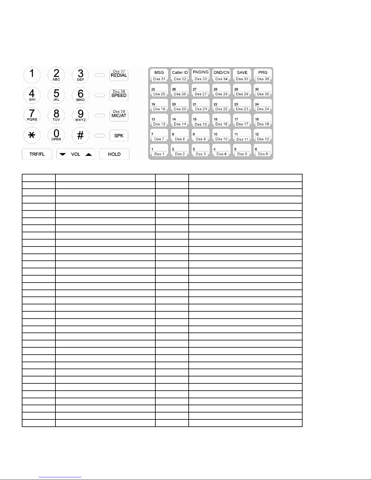
DK6 – 36 Button Layout
The Function for each FN Code
FN Code Function FN Code Function
00 One Touch DSS Speed Dial 01 Program
02 Do Not Disturb/Conference 03 Message Waiting/Pulse-Tone/Call VMU
04 Microphone/AUTO answer 05 Speed Dial
06 SAVE 07 Redial
08 Volume Up 09 Forced Account Code
10 Voice Set up 11 User Speed Dial Set Up
12 Console User Speed Dial Set up 13 Console System Speed Dial Set Up
14 Station Lock Key 15 Help List
16 Temporary Unlock / Security Code 17 Check In
18 Check Out 19 Charge Inquire
20 All Paging (Internal) 21 All Paging (External)
22 All Paging (Internal/External) 23 Zone Paging (Internal)
24 1A2 Emulation Privacy 25 Voice Mail Transfer Key
26 Swap (Call Split) 27 Answer Machine Emulation
28 Volume down 29 Headset Function key
30 Zone Paging (Internal) 7 31 Zone Paging (Internal) 8
32 Caller ID History 33 Zone Paging (External) 1
34 Voice Mail On Line Record 35 Pickup Own Group
36 Pickup All Groups 37 Pickup Group
38 Loop Key Group 1 39 Loop Key Group 2
40 Loop Key Group 3 41 Loop Key Group 4
42 Loop Key Group 5 43 Loop Key Group 6
44 Loop Key Group 7 45 Loop Key Group 8
46 Toll Password 47 Console- Morning Call Assign / Alarm
48 Alarm Assign 49 Console- Set up Alarm
50 Console- Set up System Time 51 Message Select
52 Day / Night 53 Call Forward
54 Forward Busy 55 Forward No Answer
56 Meet me Page 57 Shift Key
58 Meter Rate Setting 59 Hotel/Motel Function
60 Door Phone 61 Reserved
62 Directory key (for name search) 63 Pre-dial key
64 Day/Night/Lunch key 65
66
Page 61

Note:
1. [MSG] key: Message. It is assigned as default function key.
When a message is left on your DK phone, this [MSG] key will be flashing.
First situation (46-st-02 = 1~9):
Extension call you and presses [MSG] on their phone when you are not available. Your [MSG] key will be flashing,
pressing this flashing key will call back the caller automatically.
Second situation (46-st-02 = 0):
You have a voice message on your voice mail box, your [MSG] key will be flashing, pressing the flashing [MSG]
key will let you log into your personal voice mail box automatically.
When 46-st-02 is set to 0, pressing the MSG button will call the VMU. Its function is not dependent upon the
status of the MSG light.
2. [FN:25] key: Voice Mail Transfer. It is assigned at Program mode 7, FN code is 25
During the conversation with an outside caller transfer this call to another extension’s voice mail box by:
a. Conversation with an outside line
b. Press [FN:25] key
c. Enter the extension number that you want to transfer
d. Press [TRF] key to transfer the outside caller to the voice mail box of that extension.
Note:
In the above step d. If you want to hang up instead of press [TRF] key to transfer the call, set the parameter in
Program 05-12-01 to 2
You may directly leave a message for a station:
a. Lift the handset or press SPK.
b. Press [FN:25] key
c. Enter the extension number that you want to transfer. You will be connected directly to their mailbox and may
leave a message.
3. [FN:27] key: Answering Machine Emulation. It is assigned at Program mode 7, FN code is 27
The steps to activate this feature:
a. Set Call Forward to station [86] (that is your voice mail box number) for your keyphone.
b. Press [FN:27] key will enable the Answering machine Emulation feature.
c. Press [FN:27] key again will disable the Answering Machine Emulation feature.
Note:
1. When activated this function allows the caller to set call forward to the Voice Mail as usual but then monitor
calls to the Voice Mail from his key phone (on hook) and if they wish can lift the handset and take the call
back from the Voice Mail.
2. Another Enable method:
To enable the user presses [SPK] [7][7][3][1] and to disable presses [SPK] [7][7][3][0].
4. [FN:26] key: Swap. It is assigned at Program mode 7, FN code is 26
An extension can press this function button during a call to swap (Call Split) between two calls on separate trunks.
Refer to Program: 44-st-03
5. [FN:34] key: Voice Mail On Line Record. It is assigned at Program mode 7, FN code is 34
Record Function:
This function is dependent on the Recording Unit being capable of inserting the recording tone to alert the caller
they are being recorded. To record it is necessary for the Key phone to have a [RECORD] key which is [FN 34].
Page 62

Program 08-Gp-IP : Flexible DSS Console Key Group Assignment
08-Gp-IP KEY GRP
TK: nn
08-Gp-IP KEY GRP
xxx
08-Gp-IP KEY GRP
FN: fn
General:
This program assigns 1 group of Flexible key plan for the DSS consoles.
Description:
Each key can be assigned as a Trunk, Station or special Function.
To change the assignment from TK to Station or to Function or vice versa, press the {Change} (MIC/AT) key before
setting.
nn = 01-12 - Trunk Key (1 to 12)
xx = 10-69 - Station Key (2 digits)
xxx = 100-699 - Station Key ( 3 digits )
xxxx = 1000-6999 - Station Key ( 4 digits )
fn = 00-65 - Function Key (0 to 65)
Gp (Group)= 01, IP = (Item Pointer) 01-66 (DSS key number)
TK= Trunk number (nn)
Gp (Group)=01, IP= (Item Pointer) 01-66 (DSS key number)
xxx= Station number
Gp (Group)=01, IP= (Item Pointer) 01-66 (DSS key number)
FN= Function number (ff)
Note: For function code fn, please refer to mode 07. There is no shift key function for the DSS console.
Page 63

Program 09-nnn-DP : System Speed Dial
09-nnn-DP TK:tt mm
nnnnnnnnnnnnnnnn
nnn = 100-999 DP = 01-30
tt = 01-12 mm = 40-43
Telephone number
General:
This program permits the assignment of up to 900 sets of system speed dialing codes. If Names are enabled (default)
then only 500 Speed dials are available. If all 500 are allocated with names to System Speed dial then there are no
Personal speed dials available for users. In default 100 System Speed dials are enabled (100-199)
Description:
nnn = 100-999 = Speed dial code, up to 900 sets in total.
DP = 01-30 = Digit Pointer for telephone number. 30 digits per speed dial code.
tt = 01-12 = Pre-assigned CO line number.
mm=40 : CLI Call Blocking is enabled. It will not ring but trunk LED will be flashing.
mm=41 : CLI Call Blocking is enabled. The call will be transferred to the virtual voice mail (No. 141).
mm=42 : CLI Call Blocking is enabled. The call will be transferred to the virtual voice mail (No. 142).
mm=43 : CLI Call Blocking is enabled. The call will be transferred to the virtual voice mail (No. 143).
A VM Card must be installed to allow Call Blocking transfer to Virtual Voice Mail to be enabled.
Call Blocking is enabled in Mode 05-17-07.
Press the [MIC/AT]{Change} key twice to change or clear the settings for CLI Call Blocking.
Pre-Assigned CO Line
Press the [MIC/AT]{Change} key to change or clear the Pre-assigned CO line number. This CO line is the dedicated
outgoing line for the speed dial code. If the user presses a speed dial code without selecting a CO line first, the system
will select this CO Line automatically. If no CO line is assigned, the system will select an available CO line according to
the assigned Dial 9 group (Program 41-nnnn-04). A line may also be selected directly by the user.
Telephone Number
30 digits maximum may be entered in each memory. In addition to the digits 1 to 0, *, # the following can also be
stored: Pause, Flash, Pulse to DTMF. Each function occupies one digit.
"Pause" is represented by the [HOLD] key. -- P
"Flash" is represented by the [TRF/FL] key. -- F
"Pulse to DTMF" is represented by the {P->T} key. -- T
i) Pause:
During dial procedures on PSTN line, the dialing will wait for a programmable timer (Refer to Program 05-01-06).
During dial procedures on ISDN line, the dialing will wait for the called party to answer the call.
For example,
Store 29611356ppp506 in speed dial and use this speed dial on ISDN line to dial out. The system will dial 506 in
DTMF after the called party answers the call (it could be the Auto Attendant or Voice Mail)
ii) Flash : This will make a loop disconnection of a pre-assigned duration. (Refer to Program 05-02-05).
iii) Pulse to DTMF : If the dialed signal is "pulse", it will change to "DTMF".
Note: Pressing [DND]{Don’t Care} will erase the digit which the cursor is on.
Pressing [REDIAL]{CLR ALL} will erase all the assigned digits.
Associated program: 05-05-05, 05-04-06, 05-17-07, 43-51-05, 43-52-05, 43-53-05.
Page 64

Program 10-GP-IP : Intercom Single Digit Assignment
10-Gp-IP S.D.I.
000 000 000 000 000
General:
This program permits calling party to call one or more stations by dialing one digit only. The settings in this Program
shall be enabled by Single Digit Intercom (Refer to Program 05-04-07).
Description:
When single digit intercom is enabled then the pre-fix digit (6) of station to station call must be dialed to call another
extension.
If a particular group has no entries programmed, the stations in the same number station group will not have single
digit dialing and will not have to use the station to station prefix.
Gp = 01-08, IP = Item Pointer (01-05)
Station number for single digit dialing (1 to 5)
Page 65

Program 11-IP : Date and Time Setting
11-IP Date/Time
08 27 06 18 16 4
IP Value Item Description
11-01 01-12 Month......................
11-02 01-31 Day........................
11-03 00-99 Year.......................
11-04 00-23 Hour.......................
11-05 00-59 Minute.....................
11-06 1-7 Week day (Monday = 1, Tuesday = 2)..
General:
This program set up the system’s Date & Time.
Description:
The Date & Time will be held during power failure of G1E plus. There is no need to reset the Date & Time after power
is restored.
IP =Item pointer (01-06)
Value for each Item
Program 12-nn : System Alarm Clock
12-nn Alarm
hh mm dd
nn = Alarm schedule (01-10)
Setting Time
Location Program Program Data
Pointer Data Description
----------- ---------- ---------------------------
hh 00-23 Hour.
mm 00-59 Minute.
dd 00-99 Duration.
General:
This program permits the assignment of 10 time schedules for alarm clock purposes.
Description:
When the assigned time is reached, Background music will be broadcast over all idle Key telephones.
The time duration for alarm clock music is programmable (00 to 99 minutes.).
Lifting the handset and returning it to the cradle or pressing the SPK key will cause the background music to cease on
that telephone only.
Page 66

Program 13-nn : Password
13-nn Password
dddddddd
General:
This program permits the assignment of 9 different passwords in the system.
Description:
The password length is from 1 to 8 digits. All unused digit positions must be padded with ’d’.
nn Password Description
1 Programming Password. Default is None
2 DISA Password. Default is 3472
3 Toll Free. Default is 8655.
4 DISA Monitor. Default is 1234
5 Reserved
6 Silent Alarm password. Default is 1234
7 VMU Password. Default is 1234_ _ _ _
8 Reserved
9 Reserved
Note:
nn = Assigned Password Number (01-08)
Setting password
1. DISA Password:
The password is for DISA caller to access another CO line by DISA. Refer to “Program 05-11-05 DISA
Special Function Access” Default is 3472 (version of ATA, INT, Italy=_ _ _ _ means not available)
2. VMU Password: Default 1234. The password is used for user to access the voice mail features.
Page 67

Program 14-01-IP : SMDR Specifications
14-01-IP S.M.D.R.
0 0 0 0 0 21 0 0
IP Value Default Item Description
01 0-9 0=00 Sec. Call Duration Start Time
02 0/1 0=Record Record Incoming Call
03 0/1 0=Record Record Local Call
04 0/1 0=Record Record Incoming Call No Answer
05 0/1 0=Yes Print out the Title
06 00-99 21=21 Number of records between titles
07 0- 0= Reserved
08 0-3 0=No Polarity Reversal
General:
This program assigns the SMDR (Station Message Detail Recording) parameters.
01. Call Duration Start Time
This parameter defines the minimum access time to start recording the SMDR. It is also referred to as a Grace Timer.
IP \ Value 0 1 2 3 4 5 6 7 8 9 unit
14-01-01 0 5 10 15 20 25 30 35 40 45 sec.
02. Record Incoming Calls
This parameter determines whether incoming calls are recorded or not.
IP \ Value 0 1
IP = Item Pointer (01-08)
Value for each Item
14-01-02 Record Do not Record
03. Record Local Calls
The parameter determines whether local calls are recorded by SMDR or ignored.
The SMDR report defines whether a call is local or toll by Program 05-03-05.
IP \ Value 0 1
14-01-03 Record Do not Record
04. Record Incoming Calls No Answer
This parameter decides whether unanswered incoming calls will be recorded or not.
IP \ Value 0 1
14-01-04 Record Do not Record
05. Print out the Title
This parameter determines whether SMDR reports contain the title at the head of each page.
IP \ Value 0 1
14-01-05 Print out the Title. Do not print out the Title.
Page 68

06. Number of Records between the Title
This parameter defines the number of records between each Title. It means the total lines of record per page. A
setting of 00 will cause a heading to be printed with each call record.
07. Reserved
08. Polarity Reversal
If Polarity Reversal (PR) is disabled, the system will start counting the duration after accessing a CO line.
If Polarity Reversal (PR) is enabled, the system will start counting the duration after the called party answers.
IP Value Value Description
14-01-08 0 No PR Detection / Normal SMDR format output
14-01-08 1 PR Detection / Normal SMDR format output
14-01-08 2 No PR Detection / Simple SMDR format output
14-01-08 3 PR Detection / Simple SMDR format output
SMDR OUTPUT DATA FORMAT
ST. TK S TELEPHONE NUMBER Account MM/DD START DURATION RING UNIT
112 01 001188629645752 12345678 10/02 08:35 00:02'35"
115 02 Incoming 87654321 10/02 08:45 00:10'20" 00'10"
000 03 Incoming no answer 10/02 12:00 00'35"
112 04 001188629645752 FAC:01 10/02 12:10 00:02'00"
112 03 X FAC or PSW error 10/02 12:30
112 05 X 001 10/02 12:35 00:00'05"
121 01 # 0294150100 10/02 14:15 00:00'55"
117 01 * 0294150100 10/02 14:15 00:03'10"
D3 05 0418220212 10/02 21:01 00:02'30"
D-03 D << D I S A OFF >> 10/02 21:00 00:02'40"
112 02 DDI Num: 94150112 10/02 08:45 00:10'20" 00'10"
03 CLI NoAns:294176288 10/02 12:00 00:00'00" 00'35"
111 05 CLI Num: 294150100 10/02 12:35 00:00'05" 00'05"
05 DDI NoAns:94150112 10/02 12:37 00:00'00" 00'27"
TITLE DESCRIPTION:
ST = Station No. 11 to 6999, D = DISA
TK = Trunk No. 01 to 12,
S = Status # = Hold, * = Answered the hold, X = Cut off by toll restrictions.
Telephone Number First 24 digits
Account 8 digits in total of Forced Account Code
MM/DD Month/Day
Begin_Time hh:mm The start time of accessing the trunk line.
Duration_Tm hh:mm:ss Time duration of the call.
Ring_Tm mm:ss Incoming ring time.
Unit 00000 Meter Pulse Count
Page 69

CASE EXPLANATION:
CASE
1 October 2, 08:35 A.M., Station 112 made a call (telephone No. is 00116495256611) through line 1. The
call lasted 2 minutes and 35 seconds, Account code No. 12345678 was entered for the call and 12-meter
pulses were recorded.
2 October 2, 08:45 A.M., An incoming call on line 2, rang for 10 seconds, station 115 answered the call
and stored an Account No. 87654321.
3 October 2, 12:00 P.M., An incoming call through line 3, rang for 35 seconds, no one answered and the
call was abandoned.
4 October 2, 12:10 P.M., Station 112 made a Long Distance call through line 4 by Forced Account Code 1
and 23 meter pulses were recorded.
5 October 2, 12:30 P.M., Station 112 made a call by Forced Account Code but was denied because of a
wrong code.
6 October 2, 12:35 P.M., Station 116 made a call, which was restricted.
7 Line 1 was used by station 121 for 55 seconds then put on hold. One meter pulse was recorded against
this station for its section of the call
8 The held line 1 was answered by station 117 and he occupied the line for 3 minutes and 10 seconds.
Four meter pulses were recorded against this station for its section of the call.
9 Incoming Line 3, using the DISA function, made an outside call 018220212 on line 5. The Duration time
is for line 5. 3 meter pulses were recorded for this call.
10 DISA is completed. The Duration time is for line 3.
11 Incoming call on an ISDN system. The number displayed is the In dial number dialed by the calling party.
The system can be programmed on a station by station basis to select whether calls to that station will
display the In dial number dialed or the CLI information of the incoming caller
12 An incoming call rang for 35 seconds and no one answered. The CLI number of the calling station is
displayed.
13 An incoming call on line 5 (ISDN) was answered by station 111. The SMDR displayed the CLI number
(3039415011) of the calling party and the extension number (112) of the calling party. The extension
number shown is what the system will receive if the call is from another Transtel with ISDN. The format
may be different or non-existent from other telephone systems or on PSTN lines. The system can be
programmed on a station by station basis to select whether calls to that station will display the In dial
number dialed or the CLI information of the incoming caller. The number 94150100 is the pilot number of
the In dial group.
14 An incoming call rang for 27 seconds and no one answered. The In dial number the calling station dialed
is displayed.
Page 70

SMDR OUTPUT DATA FORMAT - With CLI Output
ST. TK S TELEPHONE NUMBER Account MM/DD START DURATION RING UNIT
112 01 001188629645752 12345678 10/02 08:35 00:02'35" 00012
112 02 DDI Num:94150112 10/02 08:45 00:10'20" 00'10"
03 CLI NoAns:294176288 10/02 12:00 00:00'00" 00'35"
111 05 CLI Num: 294150100 10/02 12:35 00:00'05" 00'05"
05 DDI NoAns:94150112 10/02 12:37 00:00'00" 00'27"
CASE
1 Outgoing call. All information remains as before.
Incoming call on an ISDN system. The number displayed is the In dial number dialed by the calling party.
2
The system can be programmed on a station by station basis to select whether calls to that station will
display the In dial number dialed or the CLI information of the incoming caller
An incoming call rang for 35 seconds and no one answered. The CLI number of the calling station is
3
displayed.
An incoming call on line 5 (ISDN) was answered by station 111. The SMDR displayed the CLI number
(294150100) of the calling party. The system can be programmed on a station by station basis to select
4
whether calls to that station will display the In dial number dialed or the CLI information of the incoming
caller. The number 94150100 is the pilot number of the In dial group.
An incoming call rang for 27 seconds and no one answered. The In dial number the calling station dialed
5
is displayed.
Note: Maximum of 25 SMDR records can be stored in the system temporarily.
Page 71

Program 17-nn : Forced Account Code
17-nn FAC CODE
__________ dd
General:
This program creates 99 Forced Account codes.
Description:
The use of forced account codes allows a station user to temporarily bypass the toll restrictions. If a Forced Account
Code is assigned to a station during system programming, it becomes the only code capable of bypassing that
station’s default toll restriction.
The forced account code can be up to eight digits in length. If the system is installed with a call accounting output the
entry for a call made using a forced account code will display the code used in the account column. The actual
numbers of the code will not be displayed for security reasons, the reading will show FAC:XX. XX is the forced account
code number 01 to 99.
The Forced Account Code will not be displayed on the screen of LCD equipped phones when it is entered.
Digit "d" is keyed in by [DND/CN] button and means "Any digit " ("don't care").
Digit "_" is keyed in by [TRF/FL] button and means "No digit ".
Clear all digits by pressing [TRF/FL] to insert a line in place of the original entry.
When entering an account code less than 8 digits in length, enter any remaining digits (up to 8) with “d” (don’t care
digits). So an entry for a forced account code of 1234 should be entered 1234dddd.
nn = Forced Account Code (01-99)
FAC code (8 digits max.) Toll class: d(Day) d(Night)
The last two digits dd are for toll class selection – Day and Night. The forced account code will open the call from the
stations normal class to the Class set for Day and Night.
First d: for Day time Toll Class.
Second d: for Night time Toll Class.
Caution:
Do not use Redial button to clear forced account code entries as this will insert "don't care" which will allow any digit
as a forced account code. This will effectively bypass all other account codes entered in the system. An entry of
“dddddddd” will cause any single digit to be accepted as a valid forced account code.
Forced Account codes are also used by the ACP (Access Control Phone) to unlock the door relay of the ACP or
system.
The Forced Account Codes may also be used as DISA passwords to allow call accounting to show which user was
making an external call using DISA from outside the system. Forced Account Codes 50 to 99 can be used for this
purpose. This feature will need to be enabled in Mode 05-11-02.
Page 72

Program 18-nn-TK : Assign Toll Plan To Trunk Lines
18-nn-tk Toll
0000000000
General:
Toll Plan allows the assignment of dialing capabilities dependent upon specific CO lines as well as individual stations.
This can be used to restrict dialing capabilities from some stations and to limit specific types of calls to certain special
purpose telephone lines.
The Toll Plans are written in Program 51 to 59 and 61 to 66.
Description:
There are total of 10 toll plans can be used.
Each Toll Plan points to a Toll Class depending on the CO line used. It is possible to allow a toll class to have different
restriction level on a line by line basis.
A station can have a Day Service toll plan and a Night Service toll plan.
Example 1: Program Mode 18-00 is set to 0000dddddd. Any station in the system which is set to toll class 0 will be
unrestricted on lines 1 to 4 but will be unable to dial out on lines 5 to 10.
Example 2: Program Mode 18-01 is set to 111100dddd. Any station in the system which is set to toll class 1 will be
restricted by toll class 1 on lines 1 to 4, will be unrestricted on lines 5 and 6 but will be unable to dial out on lines 7 and
10.
To assign toll plans to stations, see Program 41-st-05, 41-st-06.
nn = Toll Plan number (00-09), tk = Trunk No. (01-12)
Toll class for each trunk (class 0-9)
Toll Classes:
Class Function Prog. Mode
Unrestricted Default
0
Use Mode 51 for the Unrestricted numbers. Use Mode 61 for the Restricted numbers
1
Use Mode 52 for the Unrestricted numbers. Use Mode 62 for the Restricted numbers
2
Use Mode 53 for the Unrestricted numbers. Use Mode 63 for the Restricted numbers
3
Use Mode 54 for the Unrestricted numbers. Use Mode 64 for the Restricted numbers
4
Use Mode 55 for the Unrestricted numbers. Use Mode 65 for the Restricted numbers
5
Use Mode 56 for the Unrestricted numbers. Use Mode 66 for the Restricted numbers
6
Use Mode 57 for the Unrestricted numbers.
7
Use Mode 58 for the Unrestricted numbers.
8
Use Mode 59 for the Unrestricted numbers.
9
Use Mode 51-56 for unrestricted numbers. Use Mode 61-66 for all restricted numbers
*
Cannot access the trunk line.
D
Mode 51,61
Mode 52,62
Mode 53,63
Mode 54,64
Mode 55,65
Mode 56,66
Mode 57
Mode 58
Mode 59
Page 73

Program 20-nn- : Set Day – Time / Lunch Time Schedule
20-nn Day Time
00 00 00 00 00 00 00 00
General:
This program assigns day, night and lunch time from Sunday to Saturday for automatic night switching.
Description:
The system is capable of switching automatically between Day / Lunch break / Night settings using the time
parameters set in this program. To change from manual to automatic night switching the console presses [PRG]
[TRF/FL] [ *]. Pressing [*] toggles between the 3 modes.
If a Function key has been set to function 52 then pressing this key will change from Day to Night by one touch button
but will not change between Automatic and Manual switching. The meaning of nn as follow:
00 = Sunday 01 = Monday
02 = Tuesday 03 = Wednesday
04 = Thursday 05 = Friday
06 = Saturday
Example:
nn = Day schedule pointer (00-06)
Setting data
20-01 Day Time
08 30 17 00 12 30 13 30
On Monday the system will switch from Night time to Daytime start at 8:30 in the morning, will switch to lunchtime start
at 12:30, switch back to daytime at 13:30 and switch to Night time at 17:00. To program no lunchtime, enter 00 from
items 05 to 08.
Example:
Items: 01 02 (hh : mm) = the time switching from Night Time to Daytime = 08 30
Items: 03 04 (hh : mm) = the time switching from Daytime to night Time = 17 00
Items: 05 06 (hh : mm) = the time switching to Lunch Time = 12 30
Items: 07 08 (hh : mm) = the time switching to Daytime = 13 30
During Lunch Mode the system will change to night ring assignment and Auto Attendant or ACD settings but will play a
different Lunch time message.
Page 74

Program 25 : Reset Data to System Default
25 - Reset Data
0 - 9 Default
General:
This program resets all data to System Default. All new systems must be reset to default before any programming in
case corruption has been caused during handling or shipping. It will also be necessary to reset to default after a
software upgrade is installed. When using item 3 or 4 these must be done AFTER the system reset is performed.
Description:
1 = System data will be reset to system default except System Speed Dial Programming.
2 = The system data will be totally reset to system default.
WARNING: All user-defined data will be lost.
3 = For all Stations
44-st-02=1 (Hold Feature restricted)
44-st-03=1 (Call Split Feature restricted)
This feature is for Hotel/Motel operation. After setting this Mode, it is necessary to reprogram the
Console and any Administration phones in Mode 44-st-02 to allow them to place calls on hold.
4 = For all Stations
40-st-01=0 (Barge In not allowed)
40-st-02=0 (Monitor not allowed)
It is strongly recommended that this parameter is used on ALL systems to prevent accidental
Barge In operations being misinterpreted as cross talk. In some software versions these settings are 0 in default. All
other system programming information remains unchanged when using 3 or 4.
6 = Voice Prompt Copy – On-Board AA to VMU
This parameter transfers AA Greeting messages from the MBU AA Flash to the VMU Flash.
This feature takes several minutes to achieve. Do Not interrupt. When the transfer is in operation the LED on the VMU
and the LED on the MBU adjacent will fast flash in unison until the transfer is complete.
7 = Voice Prompt Copy – VMU to On-Board AA
This parameter transfers AA Greeting messages from the VMU Flash to the MBU Flash.
This feature takes several minutes to achieve. Do Not interrupt. When the transfer is in operation the LED on the VMU
and the LED on the MBU adjacent will fast flash in unison until the transfer is complete.
8 = Reset all Voice mail Box message
This parameter will clear voice message that stored in all voice mail box
9 = Reset DSP
Activate the DSP circuit in the motherboard of G1E+ and keep the rest of system still working normally.
It is used when DSP stop working and user doesn’t wish to reset the entire system.
# = update the loader, LCD displays "Update Loader SW", Press [1] to update loader.
Page 75

Program 29-tk-IP : Trunk Specifications – 2
29-tk-IP TK SPEC
0 0 0 2 0 0 0 0
IP Value Default Item Description
01 0-1 0= 0 db Trunk Receive Gain
02 0-8 0=Disable ACD-1 Function Enable
03 0~9 0= 0db Trunk Transmit Gain
04 0-8 2= Frequency 2 Set Ring Frequency (DK Handsets)
05 0-9 0=All Stations Allow Audible Ring for Incoming Calls
06 0-1 0=Disable Polarity Reverse Detection. Individual Trunk-outgoing.
07 0-9 0=Disable CO Delayed Ring Timer to Hunting Group
08 0-9 0=The 1st Hunting Group CO Delayed Ring Overflow Hunting Group
General:
This program permits each trunk line to be assigned different parameters.
01. Trunk Receive Gain
This parameter adjusts the TKU interface receive gain to adapt to different CO loop resistance. For long loop situation
where the receive audio may be low. This parameter will allow receive loudness to be boosted.
IP \ Value 0 1 2 3 4 5 6 7 8 9 unit
29-01-01 0 1 2 3 4 5 6 7 8 9 db
02. ACD-1 Function Enable
This parameter enables or disables the ACD-1 function for each trunk individually and is able to select whether ACD-1
operates in Day or Night or Both Modes.
IP Value Day Time Night Time
29-tk-02 0 Disable ACD function Disable ACD function
29-tk-02 1 Disable ACD function Enable ACD function (Note 1)
29-tk-02 2 Disable ACD function Enable ACD function (Note 2)
29-tk-02 3 Enable ACD function (Note 1) Disable ACD function
29-tk-02 4 Enable ACD function (Note 1) Enable ACD function (Note 1)
29-tk-02 5 Enable ACD function (Note 1) Enable ACD function (Note 2)
29-tk-02 6 Enable ACD function (Note 2) Disable ACD function
29-tk-02 7 Enable ACD function (Note 2) Enable ACD function (Note 1)
29-tk-02 8 Enable ACD function (Note 2) Enable ACD function (Note 2)
Note
1: Enable ACD-1 function only when all ring assigned stations are busy.
2: Enable ACD-1 function when Program 05-09-06 timer has elapsed even if ring assigned stations are idle.
Tk=Trunk No. (01-12), IP = Item Pointer (01-08)
Value for each Item
03. Trunk Transmit Gain
This parameter adjusts the TKU interface’s transmit gain to adapt to different CO loop resistance. For long loop
situation where the transmit audio may be low. This parameter will allow transmit loudness to be boosted.
IP \ Value 0 1 2 3 4 5 6 7 8 9 unit
29-01-03 0 1 2 3 4 5 6 7 8 9 db
Page 76

04. Set Ring Frequency (DK Handsets)
This feature allows each trunk to ring at DK handsets with its own individual ring frequency and override the frequency
set by the user for all calls.
IP \ Value 0 1-8
29-01-03 As per the key phone’s ring setting. Use the ringing frequency 1~8 of key phone as the trunk’s ring.
05. Allow Audible Ring for Incoming Calls
This feature allows either some or all stations which are ring assigned in Program Mode 01 or 02 to receive the
audible ring signal when a trunk rings at the station. If the audible signal is disabled the station will still be able to
answer a call by lifting the handset only, if they are ring assigned in Program Mode 01 or 02
0 = All stations assigned in Mode 01 & 02 will receive audible signal for an incoming call
1 = Only the first station assigned in Mode 01 & 02 will receive audible signal for an incoming call. Other ring
assigned stations will still be able to answer a call by lifting the handset only
2 = The first 2 stations assigned in Mode 01 & 02 will receive audible signal for an incoming call.
The other ring assigned stations will still be able to answer a call by lifting the handset only
3 to 8............
9 = The first 9 stations assigned in Mode 01 & 02 will receive audible signal for an incoming call. Other ring
assigned stations will still be able to answer a call by lifting the handset only.
06. Polarity Reverse Detection – Individual trunk-Outgoing
This parameter allows individual trunks to be enabled to detect Polarity Reverse on B party answer without having to
enable all trunks in system wide. This allows system to have a mix of lines, some of them will have reversal detection
and some not. Program Mode 14-01-08 will enable system wide Polarity Reversal settings.
IP \ Value 0 1
29-01-06 Disable Enable
07. CO Delayed Ring Timer to Hunting Group
This parameter sets the delayed ring time for an incoming call to the hunting group. If the stations in the Ring
Assignment (Mode 01/02) do not answer the incoming call within below timing, the call will overflow to the preassigned hunting group (Mode 29-TK-08). The Ring assigned stations will continue to ring.
IP \ Value 0 1 2 3 4 5 6 7 8 9 unit
29-01-07 Disable this feature 8 16 24 32 40 48 56 64 72 sec.
Related System Programming Mode: 29-Tk-07, 29-Tk-08, 67, 68, 69
08. CO Delayed Ring Overflow Hunting Group
This parameter sets the pre-assigned overflow Hunting Group for an incoming call. If the stations in the Ringing Line
Preference Assignment (Mode 01/02) do not answer the incoming call within the pre-assigned timing (Mode 29-TK-
07), the call will overflow to the pre-assigned hunting group.
IP \ Value 0 1 2 3 4 5 6 7 8 9 unit
29-01-08 1 2 3 4 5 6 7 8 9 10 Hunting Group
Related System Programming Mode: 29-Tk-07, 29-Tk-08, 67, 68, 69
Page 77

Program 35-tk-IP : Trunk Specifications – 1
35-tk-IP TK SPEC
0 1 0 0 3 0 0 0
IP Value Default Item Description
01 0-1 0=CO Trunk Type
02 0-1 1=DTMF Dialing Signal
03 0-8 0=No External Call Forward
04 0-8 0=No DISA
05 0-3 3=Yes Pick Up
06 0-9 0=No Loud Bell
07 0-5 0=Com Inward Line Ringing Type - Day
08 0-5 0=Com Inward Line Ringing Type - Night
General:
This program permits each trunk line to be assigned to different parameters.
Description:
01. Trunk Type (CO / PABX)
IP Value Value Description
35-tk-01 0 Trunk line is Central Office line.
35-tk-01 1 Trunk line is installed behind a PABX or Centrex.
When user makes a Redial Call, system will automatically add (if trunk line is installed behind PBX) or delete (If trunk
line is Central Office line) a leading digit (0 or 9 that is assigned at mode 05-03-04 PBX Outgoing code).
This setting will also force the CLI Delay Ring Time (Mode 05-14-06) for this trunk to 0.
tk =Trunk No. (01-12), IP = Item Pointer (01-08)
Value for each Item
02. Trunk Signal (Pulse / DTMF )
IP Value Value Description
35-tk-02 0 Trunk dialing signal is Dial Pulse.
35-tk-02 1 Trunk dialing signal is DTMF (Touch-Tone).
Page 78

03. External Call Forward – ECF
External Call Forwarding allows an incoming CO line to be re-directed to another location through the use of another
CO line. When a CO line senses incoming ringing, it answers the call and accesses another CO line. It then selects a
pre-programmed system speed dial number, dials the call and connects the two CO lines together.
External forwarded calls are subject to a call duration limit set in Mode 05-06-06. Valid settings for this option are
listed below:
IP Value Value Description
35-tk-03 0 No ECF.
35-tk-03 1 ECF to system speed dial 101
35-tk-03 2 ECF to system speed dial 102
35-tk-03 3 ECF to system speed dial 103
35-tk-03 4 ECF to system speed dial 104
35-tk-03 5 ECF to system speed dial 105
35-tk-03 6 ECF to system speed dial 106
35-tk-03 7 ECF to system speed dial 107
35-tk-03 8 ECF to system speed dial 108
04. DISA / ECF (Direct Inward System Access / External Call Forward)
DISA & ECF must be enabled during the time period to be utilized. They may be enabled during day service only or
night service only or both day and night service or may be disabled at all times.
The table below shows the valid setting and the resulting status:
IP Value Day Night
35-tk-04 0 DISA & ECF Disable DISA & ECF Disable
35-tk-04 1 DISA & ECF Disable DISA Enable
35-tk-04 2 DISA Enable DISA & ECF Disable
35-tk-04 3 DISA Enable DISA Enable
35-tk-04 4 DISA & ECF Disable ECF Enable
35-tk-04 5 ECF Enable DISA & ECF Disable
35-tk-04 6 ECF Enable ECF Enable
35-tk-04 7 DISA Enable ECF Enable
35-tk-04 8 ECF Enable DISA Enable
05. Pick Up
This feature is to assign "Private Lines" in conjunction with the programming of dial 9 groups, or to prevent incoming
calls being answered by users other than the ring assigned stations.
IP Value Day Night
35-tk-05 0 can not can not
35-tk-05 1 can not can
35-tk-05 2 can can not
35-tk-05 3 can can
Note:
Can = An incoming call on this line can be answered by non-ringing stations.
Can not = An incoming call on this line can not be answered by non-ringing stations.
Page 79

06. Loud Bell
Refer to Program 06 to assign Relay to operate for a Loud Bell.
IP Value Value Description
35-tk-06 0 No Operation.
35-tk-06 1 Relay on Motherboard / ACP will be activated when the trunk is ringing.
Note:
The system does not provide any voltage from the assigned relay. A separate ring voltage and ring device will need to
be provided by the installer
07. Inward Line Ringing Method Assignment (Day)
As described in Program 01-tk-IP, there are four ringing methods plus a Private line setting:
COMMON AUDIBLE RINGING
Ring all assigned Extensions simultaneously.
LINEAR RINGING
Attempt to ring the first available Extension in order of the Extensions assigned in Program 01-tk if in Day Service or
Program 02-tk if in Night Service.
CIRCULAR RINGING
The first incoming call on each trunk rings the first assigned extension, the 2nd incoming call on that trunk rings the
next assigned extension, etc.
HUNT
Provide the ability to route calls to a main answering position and provide an overflow capability so that backup
answering stations can be automatically added as necessary. If an incoming line rings an extension which is busy or
does not answer within the assigned Hunt Time (Program 05-08-01,) the call will ring the next available extension
assigned in the hunt group (Up to 16). If the next ringing station is busy then the call will immediately move to the next
ring assigned extension but if the station does not answer then the call will wait for the Hunt time and then ring the next
assigned extension. Once the ring assignment has passed a station which is busy then it will provide Off Hook Busy
Remind signal and when the station is free if the call is still unanswered the station will commence ringing for that call.
Stations which do not answer a call will also continue to ring until the call is answered.
PRIVATE
This is for an incoming private line. The station that owns this private line can set call forward (All, Busy, No Answer)
for this private line to the Voice Mail Port (See Program 43- ST-02) or off premises.
IP Value Value Description
35-tk-07 0 Day - COMMON AUDIBLE
35-tk-07 1 Day - LINEAR
35-tk-07 2 Day - CIRCULAR
35-tk-07 3 Day - HUNT
35-tk-07 4 Day – PRIVATE
Page 80

08. Inward Line Ringing Method Assignment (Night)
As described in Program 02-tk-IP, there are four ringing methods plus a Private line setting: All settings in item 08 are
the same as item 07.
IP Value Value Description
35-tk-08 0 Night - COMMON AUDIBLE
35-tk-08 1 Night - LINEAR
35-tk-08 2 Night - CIRCULAR
35-tk-08 3 Night - HUNT
35-tk-08 4 Night - PRIVATE
Trunk Name Entry
1. Enter system programming Mode 35.
2. Pressing [MIC] {Change} to enter the Name mode.
3. Input the name for the related trunk by the following function keys.
Key
Pad
1
2
3
4
5
6
7
8
9
0
*
#
Depress
1 time
Depress
2 times
Depress
3 times
Depress
4 Times
, . : 1 Space
A B C 2 ;
D E F 3 /
G H I 4 _
J K L 5 M N O 6 '
P Q R S 7
T U V 8 +
W X Y Z 9
ä ü ñ ö
% ^ & * (
$ ! @ # )
Depress
5 Times
4. Press {SAVE} to store the data.
5. The next trunk port will be appeared to be set its names.
0
Page 81

Program 36-gp-tk : Trunk Group Assignments
36-gp-IP TK GRP
04 03 02 01 00
General:
This program permits each trunk line to be assigned to different Trunk groups. There are eight groups in total.
Description:
In the bottom data-setting area, the trunk number (01-12) means that the trunk is included in the specified group.
Press [REDIAL] to clear all entries from the table before entering the required trunks. Always set outgoing calls to start
from the highest installed trunk and program in descending order to the lowest installed trunk. This will prevent call
collision particularly in systems with Single Line Telephones using CO trunks. An additional 8 groups are available by
utilizing the groups available in Mode 38 for the dial 87 trunk groups. If a station is allocated no dial 9/0 group in Mode
41-st-04 but is then allocated a Dial 87 group in mode 46-st-01 then this station will use that group as its dial 9/0 group
giving a total of 16 groups available.
Default programing for Trunk Group 1 (36-01) is as shown in the sample display above.
There are 12 trunks in total in each trunk group.
This parameter will work with the following features:
. Dial 9 or 0 access to trunk group.
. Tenant service.
Related System Programming Mode: 36, 38, 41-ST-04, 46-ST-01
gp = Group (01-08), IP = Item Pointer (01-12)
trunks to be included
Page 82

Program 37-tk : Busy Out Trunks
37-tk Busy Out
0000000000
General:
This program permits the trunk line to be locked by a Technician.
Description:
This feature is used when the user does not want to use the trunk or to remove a problem line. When the trunk is set
to BUSY OUT, the LCD display on the phone will display "Access denied " when that line button is pressed.
Value Item Description
0 Line is unlocked
1 Busy for Outgoing calls
2 Busy for Incoming and Outgoing calls (set loop on)
3 Busy for Incoming and Outgoing calls (set line LED on)
tk = Trunk No. (01-12)
Busy out Type
Page 83

Program 38-gp-tk : Dial 87 Trunk Group Assignments
38-gp-IP TK GRP
01 02 03 04 05
General:
This program permits each trunk line to be assigned to different Trunk groups which can be accessed by dialing [87].
There are 8 groups in total. This group will be available to a station in addition to or instead of it's dial 9 group. Always
set outgoing calls to start from the highest installed trunk and program in descending order to the lowest installed
trunk. This will prevent call collision particularly in systems with SLT'S. Press [REDIAL] to clear all entries in the table
before entering required trunks.
Description:
This program is different from Program Mode 36-gp-tk. This program is used for dialing [87] or [9] to access a Trunk
Line.
Once a dial [87] group has been programmed it will need to be assigned to the stations that are to use it in
Mode 46-Stn-01.
Related System Programming Mode: 36, 38, 41-ST-04, 46-ST-01
gp = Group (01-08), IP = Item Pointer (01-12)
Trunks to be included
Page 84

I
Program 39-IP : Sensor Assignments
39-STN-IP Sensor
FN S
39-STN-IP Sensor
FN S
IP Value Item Description
39-STN-01 00-18 Function No.
39-STN-02 0-2 Sensor Type
Description:
The G1E-MBU and each ACP provides 1 Sensor.
FN= Function No. S=Sensor Type
Each Sensor can be assigned to one of the following 18 functions.
FN Function
00 No Operation
01 Fire Alarm
02 Break Alarm
03 Door Phone 1
04 Reserved for future use
05 Security feature
06-18 Reserved for future use
STN = Station No. ( 00 / 000 / 0000) 2/3/4 digits
sensor on the motherboard
STN = ACP station number
Sensor on the ACP
The valid sensor types for sensor on the motherboard:
S Item Description
0 Disable Sensor function
1 Normally Open for night
2 Normally Closed for night
3 Normally Open day
4 Normally Closed Day
5 Normally open Day/Night
6 Normally Closed Day/night
The valid sensor types for sensor on the ACP:
Value Item Description
0 Disable Sensor function
1 Normally Open
2 Normally Closed
Page 85

Program 40-stn-IP : Station Class of Service – 1
40-stn-IP STCOS
0 0 0 0 0 0 0 00
IP Value Default Item Description
01 0-9 0= Not allowed Override Level
02 0-9 0= Not allowed Monitor Level
03 0-9 0=No Limit Call Duration
04 0-3 0=No Station Loud Bell
05 0-1 0=Yes Access Paging
06 0-1 0=Yes Receive Paging
07 0-1 0=None Security Code Status
08 00-99 00=All Forced Account Code
General:
This programming Mode permits each station to be assigned a different Class of Service.
Description:
01. Override Level
Higher level stations can override lower level stations. Equal levels may override each other, and lowest levels may
not override each other.
IP \ Value 0 1 2 to 8 9
40-stn-01 Disable Lowest level Highest level
stn = Station No.(2-4 digits), IP = Item Pointer (01-08)
Value for each Item
02. Monitor Level
Higher level stations can monitor lower level stations. Equal levels can not monitor each other.
IP \ Value 0 1 2 to 8 9
40-stn-02 Disable Lowest level Highest level
03: Limit call duration
Conversation will be interrupted by a Busy Tone. A warning tone will be given 10 seconds before the end of the timed
duration. (Refer to Mode 05-04-03 to set call limiting action)
IP \ Value 0 1 2 3 4 5 6 7 8 9 unit
40-stn-01 No limit 3 5 10 15 20 30 40 50 60 min.
Related System Programming Mode: 05-04-03, 40-st-03
Page 86

04. Station Loud Bell
Refer to Program 06 to assign Relay to operate for a Loud Bell.
IP Value Default
40-stn-04 0 No operation
40-stn-04 1 Operate relay on the motherboard when calls are received on this station.
The system does not provide any voltage from the assigned relay. A separate ring voltage and ring device will need to
be provided by the installer.
05. Access Paging
IP Value Default
40-stn-05 0 This station can initiate "All Page" broadcasts.
40-stn-05 1 This station cannot initiate "All Page" broadcasts.
06. Receive Paging
IP Value Default
40-stn-06 0 This station will be included in "All Page" signals.
40-stn-06 1 This station is excluded from "All Page"
This feature is useful for someone who does not want to be disturbed by paging calls.
07. Security Code Status
IP Value Default
40-stn-07 0 The station is unlocked. (Can make outgoing calls. )
40-stn-07 1 The station is locked. (Can not make outgoing calls.)
If a phone becomes locked accidentally or the user forgets their lock code, this parameter will unlock the phone. There
is no way of finding what the lock code was.
08. Forced Account Code
We can assign one of Forced Account Code for this station at this item. There are 99 forced account codes which can
be used on the system. Each user can be allocated use of one or all of these. If a station has a Forced Account Code
00-99, the user can key [PRG][4] and the force account code to override toll restrictions for one call only.
If the setting is from 01-99 then this Account Code ONLY can be used by the station. If the setting is 00 then the
station can use any one or all Account Codes. Refer to Mode 17: Create Forced Account Code
Page 87

Program 41-stn-IP : Station Specifications
41-stn-IP STSPE
1 1 0 1 0 0 SN
IP Value Default Item Description
01 1-8 1=1 Station Group
02 1-8 1=1 Key Group For Key phone
03 1-8 0=None Shift Key Group For Key phone
04 1-8 1=1 Dial 9 trunk group
05 0-9 0=0 Toll plan - Day
06 0-9 0=0 Toll plan - Night
07 SN Port Number
General:
This program permits each station to be assigned to a different Class of Service.
Description:
01. Station group
This parameter will work together with the following features:
- Call Pickup Group.
- Single Digit Intercom Group
- Paging Group
IP Value Value Description
41-stn-01 0 Disable
41-stn-01 1-8 Group 1 to 8
To select the station group for this station.
stn = Station No.(2-4 digits), IP = Item Pointer (01-07)
Value for each Item
02. Flexible key group assignments for Key phone
This parameter assigns stations to one of 8 flexible key groups.
IP Value Value Description
41-stn-02 0 Disable
41-stn-02 1-8 Key Group 1 to 8
See Mode 07: Flexible key group assignment for key phone.
03. Shift Key Group for Key phone
Each station can have access to a second soft key group accessed by the [SHIFT] key (refer to mode 07). The shift
key must be programmed in the first group assigned to the station. When the shift key is used to access the second
group then it will light red and override any function assigned to it in the second group.
IP Value Value Description
41-stn-03 0 Disable
41-stn-03 1-8 Key Group 1 to 8
See Mode 07: Flexible key group assignment to write soft key plans.
Page 88

04. Dial 9 trunk group/ SLT Port as MOH Source
When a station selects a trunk line by dialing 9, the system finds an available trunk according to the dial 9 group
assignment. If a trunk is not in a stations assigned dial 9 group then the station will not be able to make outgoing calls
on that trunk.
IP Value Value Description
41-stn-04 0 use “Dial [87] trunk group” as “Dial 9 trunk group”. (see mode 46-ST-01).
That is, Dial 9 can access the “Dial [87] trunk group”. Using this setting can
extend Dial 9 trunk groups from 8 to 16.
41-stn-04 1 search in the 1st tk group
41-stn-04 2 search in the 2nd tk group
.. ……
41-stn-04 8 search in the 8th tk group
If the Extension is an SLT port, it can be used as an additional MOH input allowing individual tenants to each have
their own Message on Hold. The port is set to type 7 in Mode 43-port-02 then in Mode 41-slt-04 user can allocate
which trunk group will use this port as a MOH source. The current drawn from the SLT port MUST be limited to no
more than 10ma to prevent damage. A line isolator will achieve this.
IP Value Value Description
41-stn-04 0 All Trunk groups
41-stn-04 1-8 Trunk group 1 to 8
Related System Programming Mode: 36, 38, 41-ST-04, 46-ST-01
05. Toll plan - Day
This parameter assigns the toll plan to be used by the station in day mode.
Refer to Mode 18 for Toll plan details.
06. Toll plan - Night
This parameter assigns the toll plan to be used by the station in night mode.
Refer to Mode 18 for Toll plan details.
07. Port Number
This is for checking only, the system will automatically show the correct port number. It is not possible for the user to
change or remove this parameter.
In the G1E, the port number consists of 2 digits
IP Value Value Description
41-stn-07 11~18 station ports on the G1E-MBU
41-stn-07 21~28 station ports on the 1st G1E-STU or G1E-SLU card
41-stn-07 31~38 station ports on the 2nd G1E-STU or G1E-SLU card
41-stn-07 41~44 SLT station ports on MBU
Page 89

Program 42-stn-IP : Register Memory Blocks for Individual Speed Dial
42-stn-IP SPD-T
b1 b2
b1: Block 1 of Individual Speed Dial Codes (00-09 or DSS11~DSS20)
b2: Block 2 of Individual Speed Dial Codes (DSS1-10) (Digital phone only)
General:
This program divides sets of Individual Speed Dial into blocks for use by Stations.
Description:
The total number of available personal speed dial numbers is determined through system programming.
If in program 05-04-06, the Individual Speed Dial Codes are assigned:
500 sets, the maximum blocks in this program are 50 blocks.
400 sets, the maximum blocks in this program are 40 blocks.
300 sets, the maximum blocks in this program are 30 blocks.
Each block has 10 sets of Individual Speed Dial.
Each set has up to 30 digits.
Speed Dial Codes 00~09 shares the same memory block with DSS11~DSS20.
Each Station can use up to 2 blocks (20 sets of Individual Speed Dial.)
If names are enabled then the number of blocks available is half.
st = Station No. (2-4 digits) IP = Item Pointer (01-02)
blocks (2 max.) for a Station
Example:
42-13-IP SPD-T
01 02
13: Station No. ( 2-4 digits )
01 02: Station 553 can use block 01 and 02 for Individual
Speed Dial (20 sets)
42-15-IP SPD-T
04 00
42-18-IP SPD-T
00 03
* Refer to Keyphone Operation for the programming of Individual Speed Dial.
* Be sure to program these parameters before programming speed dial on key phones.
If problems are encountered with stations not being able to program speed dial numbers, check this parameter to be
sure that speed dial locations are available to the station. If the station card was installed at the time of system
initialization then the blocks will have been allocated automatically.
Refer to Program Mode: 05-04-06, 05-04-05
15: Station No. ( 2-4 digits )
04 00: Station 105 can use block 04 (10 sets) for Individual
Speed Dial (00-09 or DSS11~20), 00 : for no block.
18: Station No. ( 2-4 digits )
00 03: Station 550 can use block 03 for Individual Speed Dial
(DSS 1-10)
Page 90

Program 43-cn-IP : Port Specifications
43-pn-IP Port
nnnn 0 1 0 00 02
pn = Port Number (11-56)
11~18: station port on G1E-MBU
21~28: station port on the 1st G1E-STU card.
31~38: station port on the 2nd G1E-STU or G1E-SLU card.
41~44: SLT ports on G1E-MBU.
IP Value Default Item Description
01 nnnn System Station Number (2 to 4 digits)
02 0-9 System Equipment Type
03 1-9 1=1 DSS Soft key Plan
04 0 0= Reserved
05 00-50 00= disabled Voice Mail Box Capacity
06 00-90 01=1 Minute Maximum Voice Mail Message Length
General:
This program permits each port to be assigned different parameters and station numbers.
Description:
01. Station Number
Use this setting to assign station numbers for the Flexible Numbering Plan. The allowed number range is 10-69, 100-
699. 1000-6999. If it is necessary to use digits 7 or 8 as part of the station numbering scheme then Mode 05-08-05
must first be set to 8 to prevent confusion between control codes/programming digits and Station numbers.
pn = Port No. (2 digits) IP = Item Pointer (01-06)
Value for each Item
02. Equipment Type
IP Value Value Description
43-pn-02 0 None connected
43-pn-02
43-pn-02
43-pn-02
43-pn-02
43-pn-02
43-pn-02
43-pn-02
43-pn-02
43-pn-02
43-pn-02
43-pn-02
43-pn-02
1) Types 0 to 5 and d are recognized by the system automatically.
2) Type 6 allows an SLT port to be paired to a Digital Extension providing a pseudo Hybrid port. Once set the SLT
phone can be given the same extension number as a Digital Extension and when the number is called both Phones
will ring. Either phone can answer or once one answers then a call to the same number will show busy. The call can
1 Digital Phone without LCD
2 Digital Phone with LCD
3 Not used
4 Single Line Telephone
5 DSS
6 Dual port
7 SLT Port used as MOH input.
8 Voice Mail Port
9 ISDN Device
D Door phone/ACP
- SLT Paging port (press [FLASH] for entering -
T Fax Port (press [MSG] for entering T)
Page 91

be placed on hold by one of the extensions and retrieved from the other or can be transferred to other extensions by
the normal method. The Station COS of the digital phone will be allocated to the SLT automatically.
3) Type 7 allows an SLT port to be used as an additional MOH input allowing tenanted systems to have different
messages played to different trunk groups during Call Hold. Once an SLT port is set to MOH then in Mode 41-slt-04
the port can be allocated to all or individual trunks groups as a hold source.
4) Type – allows the SLT port to be used for an External Paging Port. Both SLT Music Port and SLT Paging port
MUST have a line isolator unit installed.
5) Type 8 can be assigned to an analog port to enable the system to send DTMF tones identifying a call forwarded
call’s originating station. A voice Mail port will receive DTMF tones from call forwarded stations identifying the mail box
to which the call is intended. The mail box number must be the same as the station number for this parameter to work
although Mode 05-10 can insert leading digits before the station number is sent to the Voice Mail and is also able to
insert pauses before or during the string. There is also an Enhanced Protocol to provide more information to the Voice
Mail unit, see Mode 05-10 for descriptions of the protocols available.
6) Type 9 allows the ISDN Basic Rate to be made an “S” bus
51~52: the 1st Internal ISDN port of the 1st G1E-SIU card, and the default extension number is 141~142
53~54: the 2nd Internal ISDN port of the st G1E-SIU card, and the default extension number is 143~144
55~56: the 3rd Internal ISDN port of the 1st G1E-SIU card, and the default extension number is 145~146
51~56: Virtual Station Port, and the default extension number is 141~146.
(Virtual station port pool same port with SIU S-interface)
7) Type T is Fax port that will receive calls that transferred from trunks that are set to be Fax trunks in Mode 95-Tk-01
if a Fax CNG tone is present when DISA answers the incoming call. One fax station port is allowed.
The way to set up Fax Tone detection is below:
1. Enable DISA feature to answer the call (Mode 35-TK-04 = 3)
2. Enable detect fax tone feature by trunk (Mode 95-TK-01= 1)
3. Set Fax machine number (Mode 43-port-02= T, Pressing [MSG] for T)
03. Flexible DSS Key Group Assignments for DSS Console
This parameter assigns stations to be one of two flexible DSS console key groups.
IP Value Value Description
43-pn-03 0 Disable
43-pn-03 1-2 DSS Key Group 1 to 2
See Mode 08: Flexible DSS console key group assignment for DSS Console.
04. Reserved
05. Voice Mail Box Capacity-Virtual Mail Box
This parameter decides the total mail box message units which can be used by this extension and creates Virtual
Mailboxes. The G1E can have 6 virtual mailboxes on ports 51 to 56. These ports are shared with the ISDN “S” bus.
IP Value Value Description
43-pn-05 00 No mailbox
43-pn-05 01 5 voice units
43-pn-05 02 10 voice units
43-pn-05 03 15 voice units
43-pn-05 04 20 voice units
~ ~
43-pn-05 50 250 voice units
Page 92

Description:
1. pn= Port Number of Station.
2. The pn of virtual mail box is: 51 to 56
Each voice unit has 30 or 120 seconds storage depending on CF card and Compression rate.
Memory is 128MB / 32 Kbps compression rate:
915 voice units, each voice unit is 30 seconds, total 7.63 hours storage time.
Memory is 1GB / 64 Kbps:
1000 voice units, each voice unit is 120 seconds, total 33.34 hours storage time.
Note:
If any extension in the system dials 86 which is the mailbox access code, the VMU will answer and say “thank you for
calling, goodbye”. This tells you that the Station from which you are calling has no mailbox allocated.
06. Maximum Message Length:
To prevent a caller using up all the mail boxes capacity with a single message the length of each individual message is
limited to 1 Voice unit in default. The size of voice unit will be changed according to the size of the CF card and the
compression rate.
Example
43-18-06 Port
118 2 1 0 08 01
Means: The total mail box capacity with a 256MB VMC at 32Kbps compression for extension 118 is 40 mins (40 units,
1 minute each) and the maximum length for each voice mail message is 1 Minute .(1 units).
Extension Name Entry
1. Enter system programming Mode 43.
2. Press [MIC] to enter into the Name mode.
3. Input the name for the related extension by the following function keys.
Key Pad Depress
1 time
1
2
3
4
5
6
7
8
9
0
*
#
4. Press [SAVE] to store the data.
5. The next extension port will appear and ready to set its names.
, . : 1
A B C 2
D E F 3
G H I 4
J K L 5
M N O 6
P Q R S 7
T U V 8
W X Y Z 9
ä ü ṅ 0
% ^ & * (
$ ! $ # )
Depress
2 times
Depress
3 times
Depress
4 Times
Depress
5 Times
Page 93
Program 44-stn-IP : Station Class of Service – 2
44-stn-IP STCOS
0 0 0 0 1 0 0 0
IP Value Default Item Description
01 0-1 0=Enable System Alarm
02 0-1 0=Enable Hold feature
03 0-1 0=Enable Call Split
04 0-1 0=No Manual Line
05 0-1 1=Enable Headset Feature
06 0-1 0=Enable Use Engineering Password
07 0-1 0= Reserved
08 0-1 0=Music Station Alarm Signal
General:
This program permits each station to be assigned to a different Class of Service.
Description:
01. System Alarm
If the setting is disabled, the station will not receive system alarm clock signals.
IP Value Value Description
44-stn-01 0 Enabled - The "System Alarm" signal will be received on this station.
44-stn-01 1 Disabled -The "System Alarm" signal will not be received on this station
stn = Station No. (2-4 digits), IP = Item Pointer (01-08)
Value for each Item
02. Hold Feature
If the setting is disabled, the station will not be able to place calls on hold.
IP Value Value Description
44-stn-02 0 Enabled - Hold function allowed
44-stn-02 1 Disabled - Hold function not allowed
03. Call Split
If the setting is disabled, the station will not be able to activate call splitting function. When activated and the station
presses hook flash after placing a call on hold the call will not be retrieved. Dialing 9 (or 0) or 72 will retrieve the held
call.
IP Value Value Description
44-stn-03 0 Call Splitting function enabled
44-stn-03 1 Call Splitting function disabled
Related System Programming Mode: 07(code 26), 44-st-03
Page 94

04. Manual Line
If the setting is enabled, lifting the handset of the station will call the operator directly without dialing any digits.
IP \ Value 0 1
44-stn-04 Disabled Enabled
05. Headset Feature
When headset feature is enabled by the user (code is [SPK] [775]) they can then use the [SPK] key to go on or off
hook. If this programming mode is disabled the user cannot switch between handset and headset mode.
IP \ Value 0 1
44-stn-05 Disable Enable
06. Use Engineering Password
If the setting is disable, the station is unable to use the engineering password to enter programming mode.
IP \ Value 0 1
44-stn-06 Disable Enable
07. Reserved
08. Station Alarm Signal
This parameter decides what signal the station will hear when a station alarm or Wake-Up Call is activated.
IP Value Value Description
44-stn-08 0 (set in Mode 05-05-01) default Back Ground Music
44-stn-08 1 Busy tone
Page 95

Program 45-stn-IP : Station Class of Service – 3
45-stn-IP STCOS
0 0 0 0 0 0 0 0
IP Value Default Item Description
01 0-1 0=Disable Intercom Call Limitation
02 0- 0=No ACP hear BGM at idle state
03 0- 0=No Ringing volume increase
04 0-1 0=Yes Allow Trunk Access
05 0-1 0=Yes Intercom Calls To Different Station Groups
06 0-1 0=Yes Receive Break Alarm
07 0-1 0=Yes Allow Unrestricted Speed Dial
8 0-1 0=Yes Record Station's SMDR Data
General:
This program permits each station to be assigned to a different Class of Service.
Description:
01. Intercom Call Limitation
If this setting is enabled, the station can not make an intercom call by dialing a station number. Under this condition,
the Key Phone still can press a Flexible Key to make an intercom call or the Key Station or Analog phones can call a
station using the "Single Digit" feature.
IP \ Value 0 1
Stn=Station No. (2-4 digits), IP = Item Pointer (01-08)
Value for each Item
45-stn-01 Disable Enable
02. ACP Hear BGM at idle state
IP \ Value 0 1
45-stn-02 Disable Enable
03. Incremental Increase Ringing Volume
This parameter enables the incremental increase of Ringing Volume of an incoming trunk if called extension is not
answered.
IP \ Value 0 1
45-stn-03 Disable Enable
04. Allow Trunk Access
If this function is disabled then the station can not access any trunks for incoming or outgoing calls.
IP \ Value 0 1
45-stn-04 Enable Disable
Page 96

05. Intercom Calls to Different Station Groups
If this function is disabled then stations will not be able to make intercom calls outside their own station group (Mode
41-st-01). This parameter is for use in tenancy arrangements where each company wish's to remain totally separate
although some stations can still be allowed this function, for instance a shared Receptionist.
IP \ Value 0 1
45-stn-05 Enable Disable
06. Receive Break Alarm
If this parameter is disabled then the station will not receive the Break Alarm signal if one has been programmed in
Mode 39.
IP \ Value 0 1
45-stn-06 Enable Disable
07. Allow Unrestricted Speed Dial Access
If this parameter is disabled then the station will not be able to access any of the Speed Dial numbers which have
been unrestricted in Mode 05-05-03/04 if they conflict with the stations toll restrictions.
IP \ Value 0 1
45-stn-07 Enable Disable
08. Record Station's SMDR Data
If this parameter is disabled then calls to and from this station will not recorded or output to the SMDR for the Mini Call
Accounting feature. When the Mini Call Accounting feature is enabled (see Mode 14-01-08) then all stations which are
used for administration should have this feature disabled to prevent using memory unnecessarily to record their calls.
If calls are allowed to accumulate against stations which are not checked in or out regularly then the system memory
buffer will become full and calls will not be recorded.
IP \ Value 0 1
45-stn-08 Record Do not Record
Page 97

Program 46-stn-IP : Station Class of Service – 4
46-stn-IP STCOS
1 1 2 3 0 7 d 0
IP Value Default Item Description
01 0-8 1= 1 Dial [87] Trunk Group
02 0-9 0= 1 Send Message Wait Signal Level
03 0-2 0= Auto Answer /MIC Off Automatic Answer Capability / Internal CLIP
04 0-7 3= Recall DISA/ISDN In dial Recall Capability
05 0-9 0= No Limit Maximum Number Of Transfer Times Allowed
06 0-7 7= Yes Door Unlock/DND/CFWD Access
07 0-9, d * 0= d ACP Door Phone Hunt Grp./Permanent C/FW Grp.
08 0-7 0= Normal SLT Ring Cadence Settings
General:
This program permits each station to be assigned to a different Class of Service.
Description:
01. Dial [87] Trunk Group
If this setting is from 1 to 8, after the station dials [87] (or dials [9]), the system will automatically search for a free line
which is assigned in group 1 to 8 in Program Mode 38.
If the setting is 0, then no dial 87 group is available to this station.
Related System Programming Mode: 36, 38, 41-ST-04, 46-ST-01
stn= Station No. (2-4 digits), IP = Item Pointer (01-08)
Value for each Item
02. Message Waiting Level
The Stations assigned higher levels can leave message for stations with the same or lower levels. Ten levels (0-9)
are available (9=highest level, 0=lowest level). Stations which are set to 0 can not send a message waiting information
but only receive a message waiting from Stations which are class 9.
IP Value Value Description
46-stn-02 9 Can do Message Waiting to Stations that are assigned level 0-9
46-stn-02 8 Can do Message Waiting to Stations that are assigned level 1-8
46-stn-02 n Can do Message Waiting to Stations that are assigned level 1-n
46-stn-02 1 Only receive Message from Stations whose assigned level is > 2.
46-stn-02 0
For Hotel / Lodging applications, it is recommended that you assign a message waiting level so that guest telephones
cannot leave a message for another station in the system. If you set the guest room to 1 then the room phone cannot
leave a message for another station and can ONLY get a message waiting indication from the console operator or the
voice mail system.
Message levels of the same value above 0 can leave messages for one another. Lower message levels cannot leave
messages for higher levels.
Message level 0 is special design for plain phone without Message facility.
Can not do or get Message Waiting from others.(lowest level),
except from stations assigned as level 9.
Page 98

03. Automatic Answer Capability (Keyphone) / Internal CLI (Caller ID) Function
For Digital Key Telephone
This parameter if enabled will automatically switch on the microphone of the station if it receives an intercom call. This
setting is independent of whether the system is set to voice or ring signalling for intercom calls.
IP Value Value Description
46-stn-03 0 No
46-stn-03 1 MIC permanently on
46-stn-03 2 MIC will switch on for Intercom calls
For Single Line Telephone (Connected to G1E-SLU or SLT port on MBU):
This enables system to send internal and external CLI(Caller ID) signals to the single line telephone
IP Value Value Description
46-stn-03 0 Disable CLI sending to SLT
46-stn-03 1 Enable SDMF (number without name) CLIP sending to SLT
04. DISA/ISDN In Dial Recall Capability
This parameter affects DISA calls. When a call rings an extension but the station is busy or does not answer
(depending on setting) after the voice message announcing the status of the station is heard, the system will recall the
operator after the assigned DISA transfer time. Using the settings 1 to 3 the called station will continue to ring until the
console answers the call. Using settings 5 to 7 the call will ring the station for 1 cycle (Mode 05-08-06) and then recall
to the console and cease to ring the called station. If the parameter is set to 0 then the call will stay at the station until
answered or terminated.
IP
Value
Value Description
46-stn-04 0 No Recall to Operator
46-stn-04 1 Recall to Operator when called station is No Answer.
46-stn-04 2 Recall to Operator when called station is Busy. Camp on called station.
46-stn-04 3 Recall to Operator when called station is No Answer/Busy. Camp on called station.
46-stn-04 4 ISDN In dial calls ringing a busy station will receive busy signal.
46-stn-04 5 Recall to Operator when called station is No Answer. No Camp on function.
46-stn-04 6 Recall to Operator when called station is Busy. No Camp on function.
46-stn-04 7 Recall to Operator when called station is No Answer/Busy. No Camp on function.
46-stn-04 8 ISDN In dial calls, recall to Operator when called station is busy.
05. Maximum Re-Transferred Times
This feature allows the user or the automatic attendant console to re-transfer the same call for the number of times set
in this parameter.
IP \ Value 0 1 2 3 4 5 6 7 8 9 unit
46-stn-05 No limit 6 7 8 9 10 11 12 13 14 times
06. Door Unlock / DND / CFWD Access
This parameter allows or disallows the station from accessing the Door Unlock, Do Not Disturb (DND) and Call
Forward (CFWD) features as per the table.
IP \ Value 0 1 2 3 4 5 6 7
Door Unlock Disallow Allow Disallow Allow Disallow Allow Disallow Allow
DND Disallow Disallow Allow Allow Disallow Disallow Allow Allow
CFWD Disallow Disallow Disallow Disallow Allow Allow Allow Allow
Page 99

07. ACP Door Phone Hunt Group / Permanent Call Forward Group – No Answer
IP \ Value 0 1 2 n 9 d *
46-st-07 Group 1 Group 2 Group 3 Group n+1 10 Program 3 VMC
This parameter allocates the Station Hunt Group that the ACP will call if it is programmed as a Door Phone and the
Call button is pressed. When setting is d; the ACP will call the extension according to the assignment in Program 3:
Door Phone Ring Assignment
If the Extension is not an ACP then this parameter sets the Permanent Call Forward destination Hunt Group on No
Answer. If the Station user sets a Call Forward manually then it will override this setting but after cancelling the manual
Call forward then this setting will be enabled again.
An entry of * will set permanent Call Forward No Answer to the internal Voice Mail Card. This option should be used
when forwarding to the voice mail is desired but calls are not answered by Automated Attendant (DISA).
See also Mode 78-st-04: Call Forward Group - Busy.
08. SLT Ring Cadence Settings
If the Station is an SLT then this parameter will set the ring Cadence for calls as follows.
IP \ Value 0 1 2 3 4
46-stn-05 Normal Always Trunk ring pattern Always Intercom ring pattern Special Ring Fax Ring
Page 100

Program 47-stn-IP : Hot Line Assignment
47-stn HOT LINE
000
47-stn HOT LINE
SPD:000
General:
This feature allows a user to lift the handset and directly call a specific outside party through System Speed Dial or an
Intercom Extension without dialing any digits.
* Pressing [SPK] on a Keyphone allows the Hot line to be overridden.
Description:
1. Enter a System Speed Dial Number for an outgoing call or a Station Number for an Intercom call.
Example:
47-115 HOT LINE
SPD:101
When the user lifts the handset, the System will automatically call 941-5010 through System Speed Dial 101.
2. Press {MIC} to select a hot line Intercom. (Press again to go back to SPD assignment), the display shows:
St = Station No. (2-4 digits)
Data. ( Extension Mode )
St= Station No. (2-4 digits)
Data. ( Speed Dial Mode )
115 = Station No. ( 3 digits )
Speed Dial 101 (for example: 941-5010)
47-115 HOT LINE
00
47-115 HOT LINE
118
The Hot Line is the recommended method of connecting a Fax machine to the system. Use a spare analog port and
make the Fax extension a Hot Line to an unused Speed Dial number and allocate the fax line to be used by that
Speed Dial. Do not program any number into the Speed Dial. When the fax goes off line it will select the Fax line and
then wait for the Fax to dial the number required.
Enter an Extension number 118
The system calls Extension 118 when the handset is
lifted.
 Loading...