

Transtector I2R SuperHy 120 Installation Instructions Manual
Warning
Thank you for your recent purchase of our surge protection solution.
Your satisfaction with our product and service is important to us.
If you have any questions, comments or concerns, please contact us
at 800.882.9110 or visit our website at www.Transtector.com.
We look forward to continuing to serve your protection needs.
Installation Instructions
800.882.9110 | 208.772.8515 | www.ProtectionGroup.com
Risk of Electric Shock or Burn
• Install only in restricted access enclosure or control cabinet that
requires a key or tool to open.
• This SPD should only be installed and serviced by qualied electrical
personnel.
• All National and Local Electric Codes must be observed.
• Conrm that the SPD is rated for the voltage of the application.
• Before installation, turn off all power to equipment to prevent accidental
electric shock or injury.
• Replace all covers and doors prior to restoring power to this
equipment.
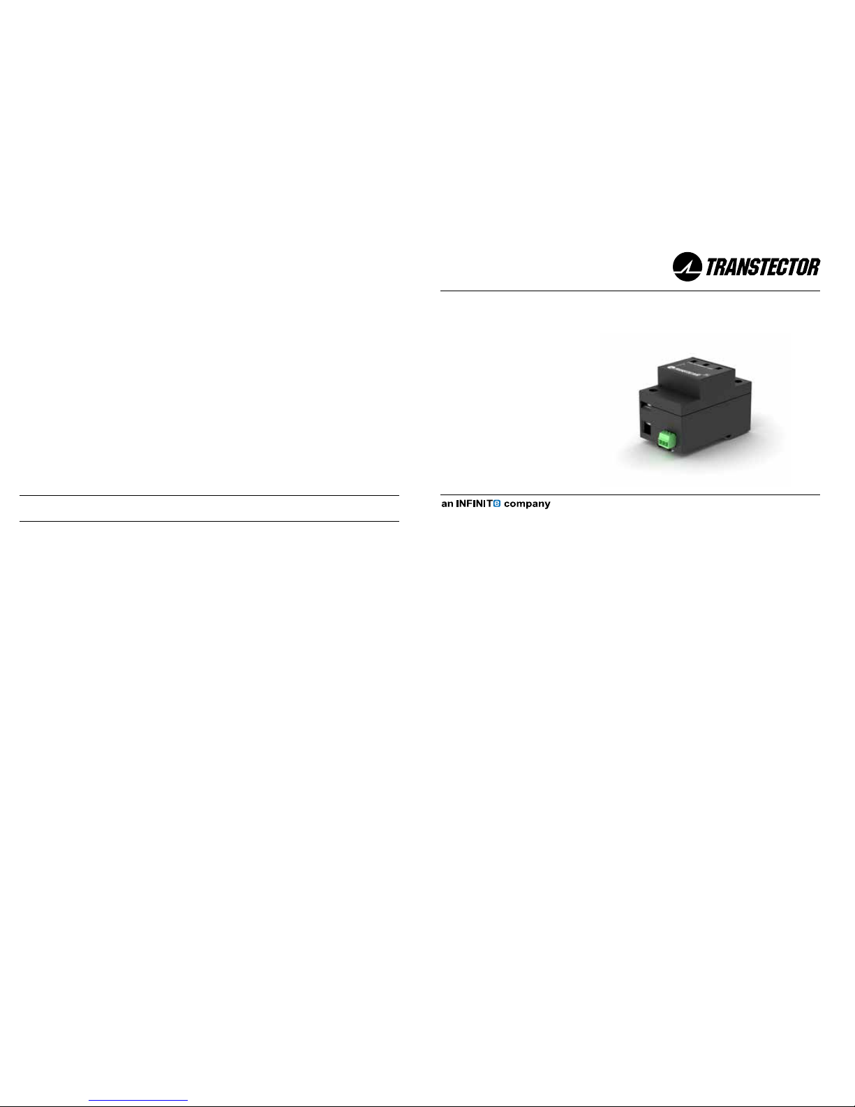
I²R SuperHy 120
Installation Instructions
800.882.9110 | 208.772.8515 | www.Transtector.com
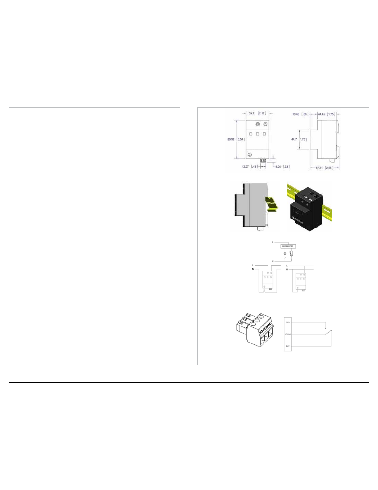
Figure 1 - Mechanical Outline Drawing (mm)
Figure 4 - Remote Contact Connections
Figure 3 - Wiring Diagram
Figure 2 - Installation
I²R SuperHy 120
INSTALLATION NOTES
The I²R SuperHy 120 is used to protect power supplies from over-voltage
caused by transients. This Surge Protection Device (SPD) offers hybrid
bidirectional silicon avalanche diode and metal oxide varistor suppression
technology and is intended for installation on the load side of the service
equipment over current device. The SPD is installed in parallel with the
load. If the lightning protection zone concept is used, this SPD installs
at the boundary of LPZ1 and LPZ2. The SPD features visual status
indication. The normally black indicator turns red if the module needs
replacement. Electrically isolated Form C dry contacts provide remote
monitoring capability. The SPD is designed to be installed in a restricted
access enclosure.
INSTALLATION INSTRUCTIONS
1. Mounting: Position the SPD as close to the equipment being protected
as possible in order to minimize the conductor length. The SPD should
be attached to a securely mounted 35mm DIN rail. The SPD shall be
mounted by positioning the terminal block end on the top edge of the DIN
rail and pressing downward until a ‘click’ is heard (see Figure 2).
2. Wiring: The SPD shall be installed in parallel with the load or electrical
system wiring using #6 - #14 AWG wire. The maximum torque to be
applied to the terminal screws is 1.6 Nm (15 lb-in). Interconnecting wire
should be no longer than 500mm (20”) in total length with a maximum bend
radius of 100mm (4”). Strip the wire insulation 8mm (5/16”). Do not loop
or twist the interconnecting wire. Determine the electrical conguration
and wire as shown in Figure 3.
3. Remote Annunciation: Electrically isolated Form C dry contacts provide
remote monitoring capability. The removable plug accepts #16 - #30
AWG wire. The continuous current rating for the remote indicator is
3A @ 125 VAC maximum. Strip the wire 6mm (1/4”), and torque the
terminal screw 0.2 Nm (1.8 lb-in). The terminal is labeled with Normally
Open (NO), Normally Closed (NC) and Common (COM). Install signal
wiring as shown in Figure 4.
USAGE AND MAINTENANCE
The SPD should be scheduled for periodic inspection to ensure the SPD is
operational and all wire connections are tight.
If the SPD is damaged, contact Transtector for replacement.
1104-15-300-M Rev A
 Loading...