

Transtector ALPU Series, ALPU-1000BT-CS-M, ALPU-POE-60V-M, ALPU-PTP-M Installation Instructions Manual

800.882.9110 | 208.772.8515 | www.transtector.com
ALPU
Conforms to UL/EN/IEC 60079-0 and UL/EN/IEC 60079-15.
ITS15ATEX48178X, IECEx ETL 15.0002X
II 3 G Ex nA IIC Gc
Class I Zone 2 Ex nA IIC Gc
Class I Zone 2 AEx nA IIC Gc
Class I Division 2 Groups A,B,C,D
locations:
This product is rated IP54 and is suitable for use in the following hazardous
We look forward to continuing to serve your protection needs.
at 800.882.9110 or visit our website at www.transtector.com.
If you have any questions, comments or concerns, please contact us
Your satisfaction with our product and service is important to us.
Thank you for your recent purchase of our surge protection solution.
aux zones dangereuses.
5. Le remplacement d’un composant interne est interdit et risque de nuire à son adaptation
inammables de gaz ou de vapeurs combustibles.
Débranchez-le uniquement si vous êtes sûr que la zone est exempte de concentrations
4. RISQUE D’EXPLOSION. Ne débranchez pas le produit si le circuit est sous tension.
3. L’installation doit uniquement être effectuée par un électricien qualié.
2. Le dispositif antiparasite interrompra les communications en cas d’abnégation.
avant d’installer ce produit. Conservez ces consignes pour les consulter plus tard.
1. Consignes de sécurité importantes. Veuillez lire et comprendre toutes les consignes
Avertissement
diameter: 0.25” to 0.30”) is required.
6. For outdoor or hazardous location applications, outdoor rated Cat5E cable (outer
hazardous locations.
5. Substitution of any internal component is prohibited and may impair suitability for
to be free of ignitable concentrations of ammable gases or vapors.
4. EXPLOSION HAZARD. Do not disconnect while circuit is live or unless the area is known
3. Installation shall be performed by qualied electrical technician only.
2. The suppressor will interrupt communications in the event of self-sacrice.
product. Save these instructions for future reference.
1. Important safety instructions. Read and understand all instructions before installing this
Installation Instructions
ALPU
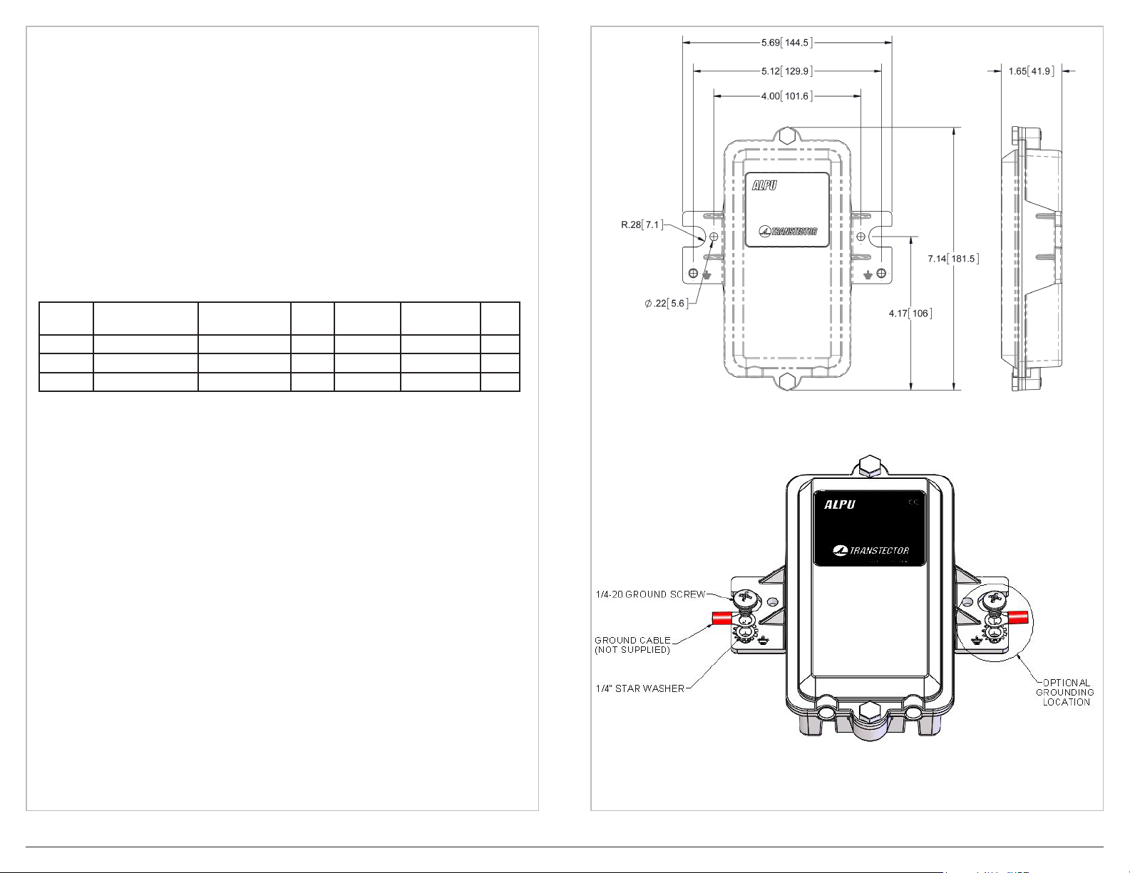
1. The ALPU SERIES is intended to be installed indoors or outdoors, on wall or pole
mount applications. The unit features mounting feet on the sides that mount on 4” centerto-center holes with #10 sized hardware. The mount foot also adapts to 4” diameter pole
mounting kits with a 4.5” center-to-center holes and larger hardware. Refer to Figure 1
for mechanical requirements and connector locations. The optimum ground connection on
the metal enclosure unit at the mounting ange on either side is shown in Figure 2. Use
minimum 8AWG wire for a ground reference attachment. Communication cables with the
RJ45 connectors already installed can feed directly into the enclosure. Be sure to install the
cables with the unprotected cable installed into the left “in” jack and the protected equipment
cable in the right “out” jack. The enclosure features a built in cable retention that grips the
cable with a screw down bracket.
A pole mount adapter kit (pn 1000-1164) is available to meet installations on a wide range of
pole diameters from 2” metal fence poles to 10” diameter utility poles.
Model Name Description MCOV Line Current
1101-935 ALPU-1000BT-CS-M ALPU GbE 6 Vdc 1A (4A total) -40°C to +70°C T6
1101-933 ALPU-POE-60V-M ALPU 10/100 PoE 60 Vdc 1A (4A total) -40°C to +70°C T6
1101-959 ALPU-PTP-M ALPU GbE PoE 85 Vdc 1A (4A total) -40°C to +70°C T6
2. Mount the device as close to the equipment to be protected as possible using the provided
hardware. Mount the unit in the orientation shown, with the strain reliefs facing the ground.
INSTALLATION INSTRUCTIONS
1. Remove the cover by removing the screw on the front of the unit.
2. Mount the unit to an outside surface using the two mounting holes shown in Figure 1.
3. Connect the Ethernet cable between the indoor unit and the suppressor using the
RJ45 jack.
4. Connect one Ethernet cable between the outdoor unit and the suppressor using an
RJ45 jack.
5. Attach appropriate wire gauge 8AWG as short as possible (less than 3 feet) between
the unit and the site grounding point using 1/4” hardware provided in the location shown
in Figure 2. Torque to 40-45 in-lbf. Refer to local codes and equipment manufacturers
standards before installation
6. Replace cover and secure with the two screws removed in step 1. Torque to 40-45 in-lbf.
CABLE REQUIREMENTS
If the ALPU SERIES is used in a Hazardous Location, the following cable requirements must
be met:
1. The cable must be 8 conductor (4 twisted pairs), 24AWG, Outdoor Rated
(-40°C to +80°C), Cat5e
2. The outer diameter of the cable must be .250-.300 inches.
3. The outer jacket material must be PVC
Operating
Temp.
Temp.
Class
Figure 1. Mechanical outline drawing (inches)
USAGE AND MAINTENANCE
The SPD should be scheduled for periodic inspection to ensure the SPD is operational and
all wire connections are tight.
If the SPD is damaged, contact Transtector for replacement.
800.882.9110 | 208.772.8515 | www.transtector.com
Figure 2. Ground Cable Installation
1200-463 Rev C
 Loading...