

Transtector ALPU Fit, ALPU-F140 Installation Instructions Manual
Warning
Thank you for your recent purchase of our surge protection solution.
Your satisfaction with our product and service is important to us.
If you have any questions, comments, or concerns, please contact us
at 800.882.9110 or visit our website at www.Transtector.com.
We look forward to continuing to serve your protection needs.
Installation Instructions
800.882.9110 | 208.772.8515 | www.Transtector.com
Unit must be properly grounded prior to use. Failure to do so will result
in voided warranty and possible equipment damage.
ALPU Fit
ALPU-F140
Installation Instructions
800.882.9110 | 208.772.8515 | www.Transtector.com
ALPU Fit
ALPU-F140
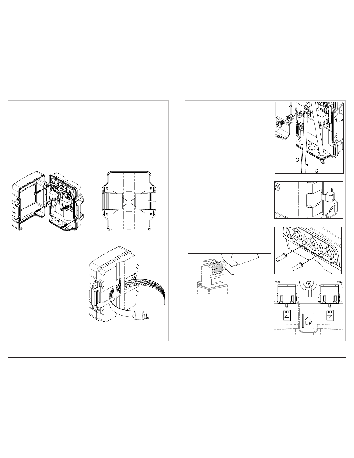
WALL MOUNT INSTALLATION INSTRUCTIONS
1. Cable openings must be oriented towards the ground.
2. Open lid of unit to access wall mount holes (see Figure 1).
3. Use quantity 2 to 4 M3.5 (or #6) fasteners to secure to desired surface. If using
only 2 fasteners, install per the following pairs (1,1), (2,2), or (3,3). (See Figure 2
for fastener congurations).
4. Do not torque fasteners greater than 1 Nm (8.8 in-lbf) ±10%.
1
1
2
2
3
3
Figure 1 - Wall mount installation Figure 2 - Fastener conguration
POLE MOUNT INSTALLATION
INSTRUCTIONS
1. Cable openings must be oriented
towards the ground.
2. Slide hose clamp or tie wrap through
two slots on back of the unit (see
Figure 3).
3. Align channel in unit with pole and
secure with hose clamp. Do not
over-tighten hose clamp as this may
cause damage to the plastic bars in
the hose clamp region of the unit.
CABLE INSTALLATION INSTRUCTIONS
WARNING! - Ground lug must be secured
as indicated below to ensure proper product
performance.
1. Secure ground lug with M5 (#10) screw
(provided as installed with unit). Torque to
1 Nm (8.8 in-lbf) ±10% (see Figure 4).
2. Push the tear-away caps over the cable
entry points out with a screwdriver or other
small diameter, blunt object.
3. Verify that each cable is aligned with the
opening directly below when closing the lid.
4. Lid should snap closed and a zip tie or tie
wrap must be used as a locking feature
(see Figure 5, tie wrap included).
Figure 3 - Pole mount installation
Figure 6 - Drain plug removal
DRAIN PLUG REMOVAL
INSTRUCTIONS (OPTIONAL)
1. To open optional drain holes, pull nubs
found on grommet which are marked by a
teardrop icon.
2. Plugs should tear away from grommet to
reveal the drain holes (see Figure 6).
Figure 4 - Cable installation
ICON INFORMATION
1. There are three icons visible when the unit
is open (see Figure 7). The icon located in
center denotes orientation of the unit.
2. The icon with up arrow indicates
unprotected signal entry, while the icon
with down arrow indicates protected signal
transmitted out.
Figure 7 - Icon information
Figure 5 - Tie wrap placement
DIELECTRIC GREASE APPLICATION
1. To protect the RJ45 connections from
corrosion, apply enough of the provided
dielectric grease to the plug end of each
cable.
2. Ensure coverage across all pin contact
areas on both RJ45 plugs prior to inserting
for nal installation (see Figure 8 below).
COVER ALL PINS
WITH DIELECTRIC
GREASE PROVIDED
Figure 8 - Grease application
1402-043 REV D
 Loading...