

Transtecno TT100 series User Manual

TT100
·A·
CONTENTS
I. Product ………………………………………………………………..
1.1 Product model naming rule….………………………………
1.2 Optional function naming rule………………………………
1.3 Nameplate……..……………………………………………
1.4 Appearance…………….……………………………………
1.5 Technical Specifications ……………………………………
1.6 Designed Standards for Implementation……………………
1.7 Safe Instructions………………………………………………
1.8 Precautions……………………………………………………
1.9 Examination and Maintenance…………………………..……
II. Keypad panel……………………………………………………..…
2.1 Panel Illustrations……………………………………………
2.2 Panel Structure………………………………………………
2.3 Panel Operating ……………………………………………
2.4 Parameters Setting …………………………………………
2.5 Function Codes Switchover In/Between Code-Groups…..…
2.6 Panel Display ………………………………………………
III. Installation & Connection ………………………………………………
3.1 Installation……………………………………………………
3.2 Connection ……………………………………………………
3.3 Function of Control Terminals……………………………………
3.4 Wiring Recommended…………………………………………
3.5 Lead Section Area of Protect Conductor(grounding wire) ……
3.6 Overall Connection………………………………………………
IV. Operation and Simple Running ………………………………………
V. Function Parameters ……………………………………………………
5.1 Basic Parameters………………………………………………
5.2 Operation Control ……………………………………………..
1
1
1
2
2
4
5
5
6
7
8
8
9
9
10
10
11
12
12
12
14
17
17
18
19
26
26
34

TT100
·B·
5.3 Multifunctional Input and Output Terminals……………………
5.4 Analog Input and Output………………………………….…
5.5 Pusle input and output………………………………….……
5.6 Multi-stage Speed Control…………………….………………
5.7 Auxiliary Functions………………………………..…….……
5.8 Malfunction and Protection……………………………………
5.9 Parameters of the motor………………………………………
5.10 Communication parameters……………………………………
5.11 PID parameters…………………………………………….
Appendix 1 Trouble Shooting…………………………………..…….
Appendix 2 Products and Structure List…………………..…………..
Appendix 3 Selection of Braking Resistance ………………………….….
Appendix 4 Communication Manual………………………………….
Appendix 5 Zoom Table of Function Code ……………………….………
41
45
50
52
54
56
58
58
59
60
61
65
66
75

TT100
·1·
I. Product
This manual offers a brief introduction of the installation connection for TT100 series
inverters, parameters setting and operations, and should therefore be properly kept. Please
contact manufacturer or dealer in case of any malfunction during application.
1.1 Product model naming rule
TT100 – 0007 S2
1.2 Optional function naming rule
D F1 Y K B R
Mark
0002
0004
0007
……
Motor power(kw)
0.2
0.4
0.75
……
Mark
Built-in EMIfilter
None
None
R
Including built-in EMI filter
Mark
Built-in braking unit
None
None
B
Including built-in braking unit
Mark
Operation panel with potentiometer
None
Local operation panel without potentiometer
K
Local operation panel with potentiometer
Mark
Operation panel type
None
Operation panel is not removable.
Y
Operation panel is removable, to be controlled remotely.
Mark
Scene bus type
None
No communication function
F1
With MODBUS communication function
Mark
Structure code
None
Hanging type
D
Cabinet type
Relation
Input power type:
S2 means single-phase 230VAC
T3 means three-phase 400VAC
Motor power
Product series
TT100
·2·
1.3 Nameplate
Taking for instance the TT100 series
0.75KW inverter with 1-phase input, its
nameplate is illustrated as Fig 1-1.
1Ph: single-phase input; 230V, 50/60Hz:
input voltage range and rated frequency.
3Ph: 3-phase output; 4.5A, 0.75KW:
rated output current and power;
0.50~650.0Hz: output frequency range.
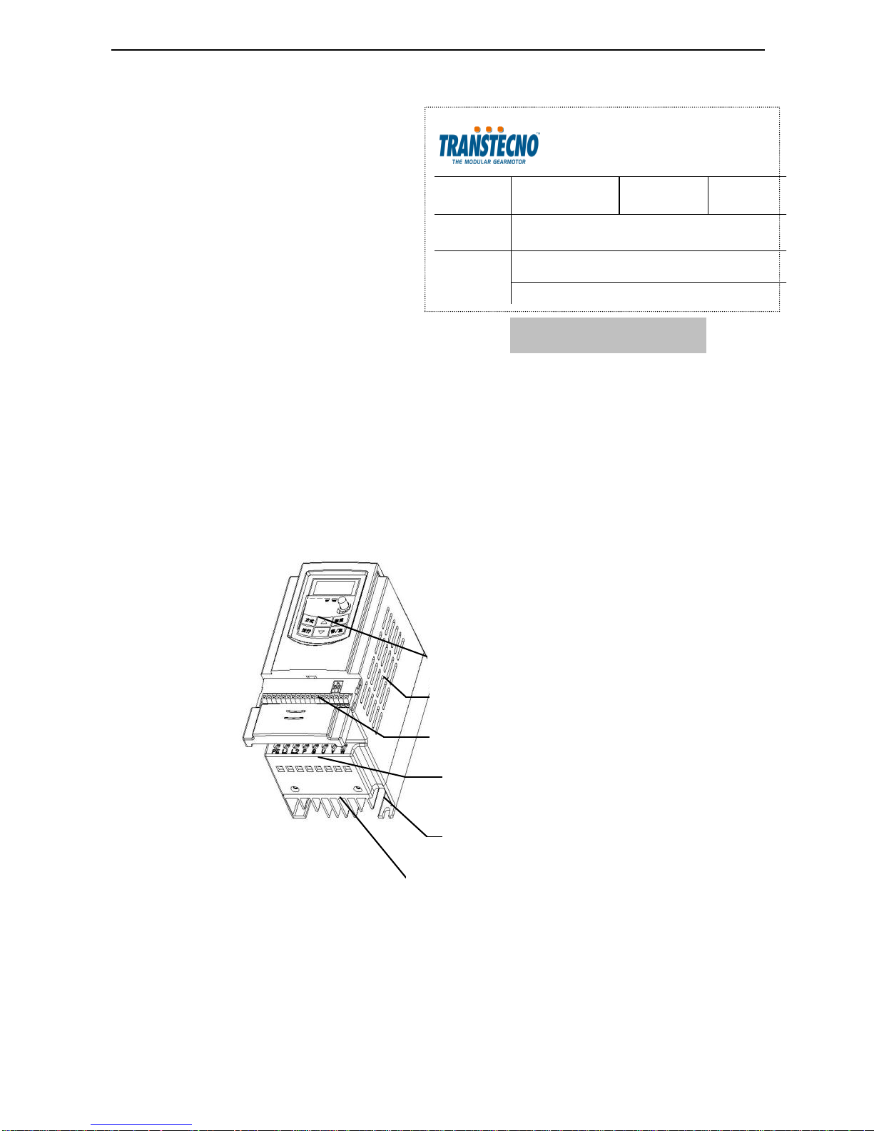
1.4 Appearance
The external structure of TT100 series inverter is classified into plastic and metal housings.
And wall hanging type is adopted. Good poly-carbon materials are adopted through
die-stamping for plastic housing with nice form, good strength and toughness.
Taking TT100-0007S2 for instance, the external appearance and structure are shown as in
below Fig.
Vent Hole
Control Terminal
Keypad Controller
Power Terminal
Mounting Hole
Heatsink
Fig 1-1 Nameplate
MODEL
TT100-0007S2
Function
Symbol
F1KBR
INPUT
AC 1PH 230V 50/60Hz
OUTPUT
3PH 0.75KW 4.5A 0~230V
0.50~650.0Hz

TT100
·3·
1.5 Technical Specifications
Table1-1 Technical Specifications for TT100 Series Inverters
Items
Contents
Input
Rated Voltage Range
3-phase 400V±15%; single-phase 230V±15%
Rated Frequency
50/60Hz
Output
Rated Voltage Range
3-phase 0~400V;3-phase 0~230V
Frequency Range
0.50~650.0Hz
Control
Mode
Carrier Frequency
2000~10000Hz; Fixed carrier-wave and random carrier-wave
can be selected by F159.
Input Frequency Resolution
Digital setting: 0.01Hz, analog setting: max frequency0.1%
Control Mode
VVVF control
Overload Capacity
150% rated current, 60 seconds.
Torque Elevating
Auto torque promotion, Manual Torque Promotion
0.1%~30.0% (VVVF)
V/F Curve
3 kinds of modes: beeline type, square type and
under-defined V/F curve.
DC Braking
DC braking frequency: 1.0~5.0 Hz, braking time: 0.0~10.0s
Jogging Control
Jogging frequency range: min frequency~ max frequency,
jogging acceleration/deceleration time: 0.1~3000.0s
Auto Circulating Running and
multi-stage speed running
Auto circulating running or terminals control can realize
15-stage speed running.
Built-in PID adjusting
Easy to realize a system for process closed-loop control
Operation
Function
Frequency Setting
Potentiometer or external analog signal (0~5V, 0~10V,
0~20mA); keypad (terminal)▲/▼ keys, external
control logic and automatic circulation setting.
Start/Stop Control
Terminal control, keypad control or communication control.
Running Command Channels
3 kinds of channels from keypad panel, control terminal and
series communication port.
Frequency Source
Frequency sources: given digit, given analog voltage, given
analog current and given series communication port.
Accessorial frequency Source
Flexible implementation of 5 kinds of accessorial frequency
fine adjustments and frequency compound.
Optional
Built-in EMI filter, built-in braking unit, Modbus communication, telecontrol panel
Protection
Function
Input out-phase, Output out-phase, input under-voltage, DC over-voltage, over-current,
over-load, current stall, over-heat, external disturbance
Display
LED nixie tube showing present output frequency, present rotate-speed (rpm), present output
current, present output voltage, present linear-velocity, types of faults, and parameters for the
system and operation; LED indicators showing the current working status of inverter.
Environment
Conditions
Equipment Location
In an indoor location, Prevent exposure from direct
sunlight, Free from dust, tangy caustic gases, flammable
gases, steam or the salt-contented, etc.
Environment Temperature
-10℃~+50℃
Environment Humidity
Below 90% (no water-bead coagulation)
Vibration Strength
Below 0.5g (acceleration)
Height above sea level
1000m or below
TT100
·4·
Protection
level
IP20
Applicable
Motor
0.2~15KW
1.6 Designed Standards for Implementation
IEC/EN 61800-5-1: 2003 Adjustable speed electrical power drive systems
safety requirements.
IEC/EN 61800-3: 2004 Adjustable speed electrical power drive systems-Part
3: EMC product standard including specific test methods.
1.7 Safe instructions
Please check the model in the nameplate of the inverter and the rated value of
the inverter. Please do not use the damaged inverter in transit.
Installation and application environment should be free of rain, drips, steam,
dust and oily dirt; without corrosive or flammable gases or liquids, metal
particles or metal powder. Environment temperature within the scope of -10℃~
+50℃.
Please install inverter away from combustibles.
Do not drop anything into the inverter.
The reliability of inverters relies heavily on the temperature. The around
temperature increases by 10℃, inverter life will be halved. Because of the wrong
installation or fixing, the temperature of inverter will increase and inverter will
be damaged.
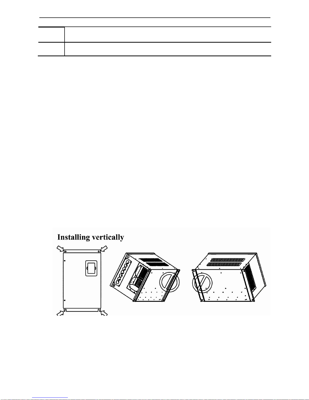
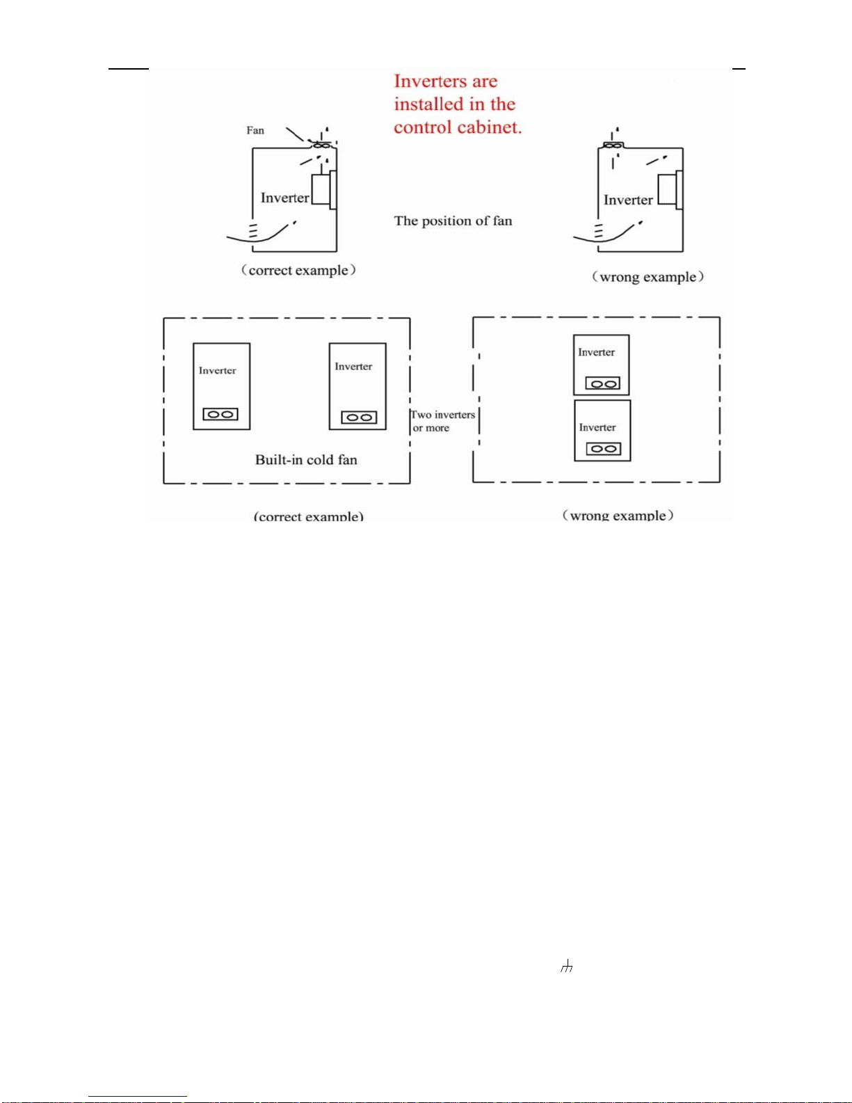
If inverter is installed in a control cabinet, smooth ventilation should be ensured
and inverter should be installed vertically. If there are several inverters in one
cabinet, in order to ensure ventilation, please install inverters side by side. If it is
necessary to install several inverters up and down, please add heat-insulation
plate.
TT100
·5·
1.8 Precautions
1.8.1 Instructions for use
Never touch the internal elements within 15 minutes after power off. Wait till it
is completely discharged.
Input terminals R, S and T are connected to power supply of 400V while output
terminals U, V and W are connected to motor.
Proper grounding should be ensured with grounding resistance not exceeding
4Ω; separate grounding is required for motor and inverter. Grounding with
series connection is forbidden.
Load switch is forbidden at output while inverter is in operation.
AC reactor or/and DC reactor is recommended when your inverter is above 37KW.
There should be separate wiring between control loop and power loop to avoid
any possible interference.
Signal line should not be too long to avoid any increase with common mode
interference.
It shall comply with the requirements for surrounding environment as stipulated
in Table 1-1 “Technical Specifications for TT100 Series Inverter”.
1.8.2 Special Warning!!
Never touch high-voltage terminals inside the inverter to avoid any electric shock.
Before inverter is powered on, please be sure that input voltage is correct.
Please do not connect input power supply onto U,V,W or terminals.
Please do not install inverter directly under sunshine, do not block up the cooling hole.

TT100
·6·
All safety covers should be well fixed before inverter is power connected, to
avoid any electric shock.
Only professional personnel are allowed for any maintenance, checking or
replacement of parts.
No live-line work is allowed.
1.9 Maintenance
1.9.1 Periodic Checking
Cooling fan and wind channel should be cleaned regularly to check whether it is
normal; remove the dust accumulated in the inverter on a regular basis.
Check inverter‟s input and output wiring and wiring terminals regularly and
check if wirings are ageing.
Check whether screws on each terminals are fastened.
Check whether inverter is corrosive.
1.9.2 Replacement of wearing parts
The wearing parts include cooling fan and electrolytic capacitors.
The life of the fan usually is 2~3 years. Users should change the cooling fan
according to all running time of inverter. Cooling fan could be damaged
because bearing is damaged and fan blades are aging. Users could check fan
blades for cracks or check the abnormal vibration noise when starting. Users
could change fan according to abnormal phenomena.
The useful life of electrolytic capacitors is 4~5 years. Users should change the
electrolytic capacitors according to all running time of inverter. Capacitors
could be damaged because the power supply is unstable, the environment
temperature is high, frequent over-load occurs and electrolyte is ageing. By
checking whether there is leakage of liquid, or the safety valve bulges out, or
the static electricity and insulated resistor is ok, users could change the
capacitor according to these phenomena.
1.9.3 Storage
Please put the inverter in the packing case of manufacture.
If inverter is stored for long time, please charge the inverter within half a year
to prevent the electrolytic capacitors damaged. The charging time should be
longer than 5 hours.
1.9.4 Daily Maintenance
Environment temperature, humidity, dust and vibration would decrease the life of
inverter. So daily maintenance is necessary to inverter.
Daily inspecting:
Inspecting for noise of motor when it is working.
Inspecting for abnormal vibration of motor when it is working.
Inspecting for the installing environment of inverter.
Inspecting for the fan and inverter temperature.
Daily cleaning:
Keep the inverter clean. Clean surface dust of inverter to prevent dust, metal
powder, oily dirt and water from dropping into the inverter.Inspecting for the fan
and inverter temperature.
Daily cleaning:
Keep the inverter clean. Clean surface dust of inverter to prevent dust, metal
powder, oily dirt and water from dropping into the inverter.

TT100
·7·
II. Keypad panel
Keypad panel and monitor screen are both fixed on keypad controller. Two kinds of controllers (with and
without potentiometer) are available for TT100 series inverters. Refer to note for Fig2-1.
2.1 Panel Illustration
The panel covers three sections: data display section, status indicating section and keypad operating section,
as shown in Fig. 2-1.
Instructions for operation panel:
Operation panels of below 15KW can not be pulled out. Please select AA or A6 control panel to realize
remote control, which is connected by 4 core telephone wire.
.
Operation panel
RUN FWD DGT FRQ
Min Max
Fun
Set
▲
▼
Run
stop
reset
4 LEDs indicate working status. RUN is lighting while running. FWD is lighting
when working forward and FRQ is lighting when showing frequency.
LED shows running frequency, flashing target frequency, function code,
parameter value or fault code.
Press “Fun” for function code, and “set” for original parameters.▲
and▼keys can be used to select function codes and parameters.
Press “set” again to confirm. In the mode of keypad control, ▲and
▼keys can also be used for dynamic speed control. “Run” and
“Stop/Reset” keys control start and stop. Press “Stop/Reset” key to
reset inverter in fault status.
Potentiometer can be used for manual speed control in mode of
analog signals control. External potentiometer or external analog
signal can also be used.
Fun
Set
▲
▼
Run
Stop
reset
RUN FWD DGT FRQ
LED shows running frequency, flashing target frequency, function code,
parameter value or fault code.
4 LEDs indicate working status. RUN is lighting while running. FWD is lighting
when working forward and FRQ is lighting when showing frequency.
Press “Fun” for function code, and “set” for original parameters.▲
and▼keys can be used to select function codes and parameters.
Press “set” again to confirm. In the mode of keypad control, ▲and
▼keys can also be used for dynamic speed control. “Run” and
“Stop/Reset” keys control start and stop. Press “Stop/Reset” key to
reset inverter in fault status.
Operation panel
Fig.2-1 Operation Panels in Two Kinds

TT100
·8·
2.2 Panel structure
1. structure diagram
2. Structure size (Unit: mm)
Code A B C D
H
Opening size
AA
76
52
72
48
24
73*49
A6
124
74
120
70
26
121*71
2.3 Panel Operating
All keys on the panel are available for user. Refer to Table 2-1 for their functions.
Table 2-1 Uses of Keys
Keys
Names
Remarks
Fun
To call function code and switch over display mode.
Set
To call and save data.
Up
To increase data (speed control or setting parameters)
Down
To decrease data (speed control or setting parameters)
Run
To start inverter;
Stop or reset
To stop inverter; to reset in fault status; to change function codes in a code
group or between two code groups.
Fun
Set
Run
Stop/reset
▲
TT100
·9·
2.4 Parameters Setting
This inverter has numerous function parameters, which the user can modify to effect different modes of
operation control. User needs to realize that if user sets password valid (F107=1), user‟s password must be
entered first if parameters are to be set after power off or protection is effected, i.e., to call F100 as per the
mode in Table 2-2 and enter the correct code. User‟s password is invalid before delivery, and user could set
corresponding parameters without entering password.
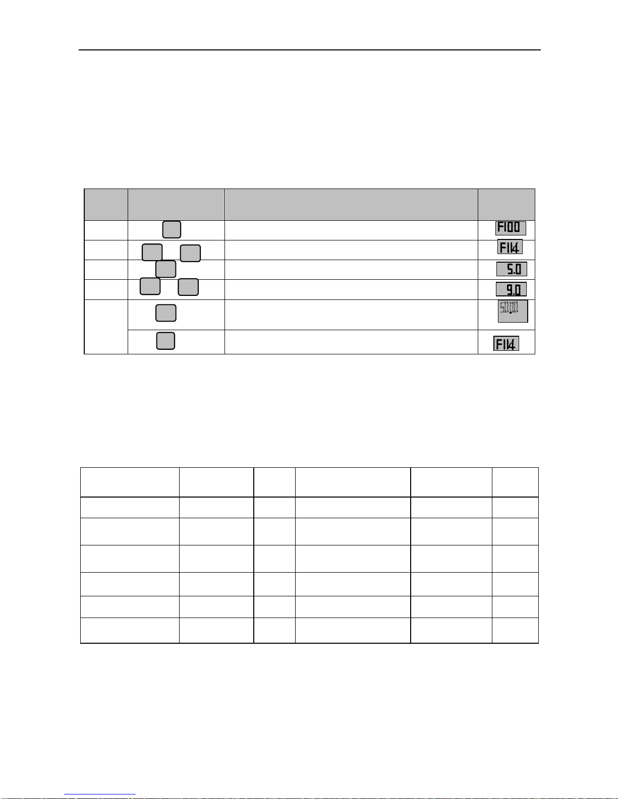
Table 2-2 Steps for Parameters Setting
Steps
Keys
Operation
Display
1 Press “Fun” key to display function code
2 Press “Up” or “Down” to select required function code
3
To read data set in the function code
4 To modify data
5
To show corresponding target frequency by flashing
after saving the set data
To display the current function code
The above-mentioned step should be operated when inverter is in stop status.
2.5 Function Codes Switchover in/between Code-Groups
It has more than 300 parameters (function codes) available to user, divided into 10 sections as indicated in Table 2-3.
Table 2-3 Function Code Partition
Group Name
Function
Code Range
Group
No.
Group Name
Function
Code Range
Group
No.
Basic Parameters
F100~F160
1
Subsidiary function
F600~F630
6
Run Control Mode
F200~F230
2
Timing control and
protection function
F700~F740
7
Multi-functional
input/output terminal
F300~F330
3
Parameters of the motor
F800~F830
8
Analog signals of
input/output
F400~F439
4
Communication
function
F900~F930
9
Pulse of input/output
F440~F460
4
PID parameter setting
FA00~FA30
10
Multi-stage speed
parameters
F500~F580
5
As parameters setting costs time due to numerous function codes, such function is specially designed as
“Function Code Switchover in a Code Group or between Two Code-Groups” so that parameters setting
become convenient and simple.
Press “Fun” key so that the keypad controller will display function code. If press “▲” or “▼” key then,
Fun
▲
▼
or
Set
Set
Fun
▲
▼
or
TT100
·10·
function code will circularly keep increasing or decreasing by degrees within the group; if press the
“stop/reset” key again, function code will change circularly between two code groups when operating the
“▲” or “▼” key.
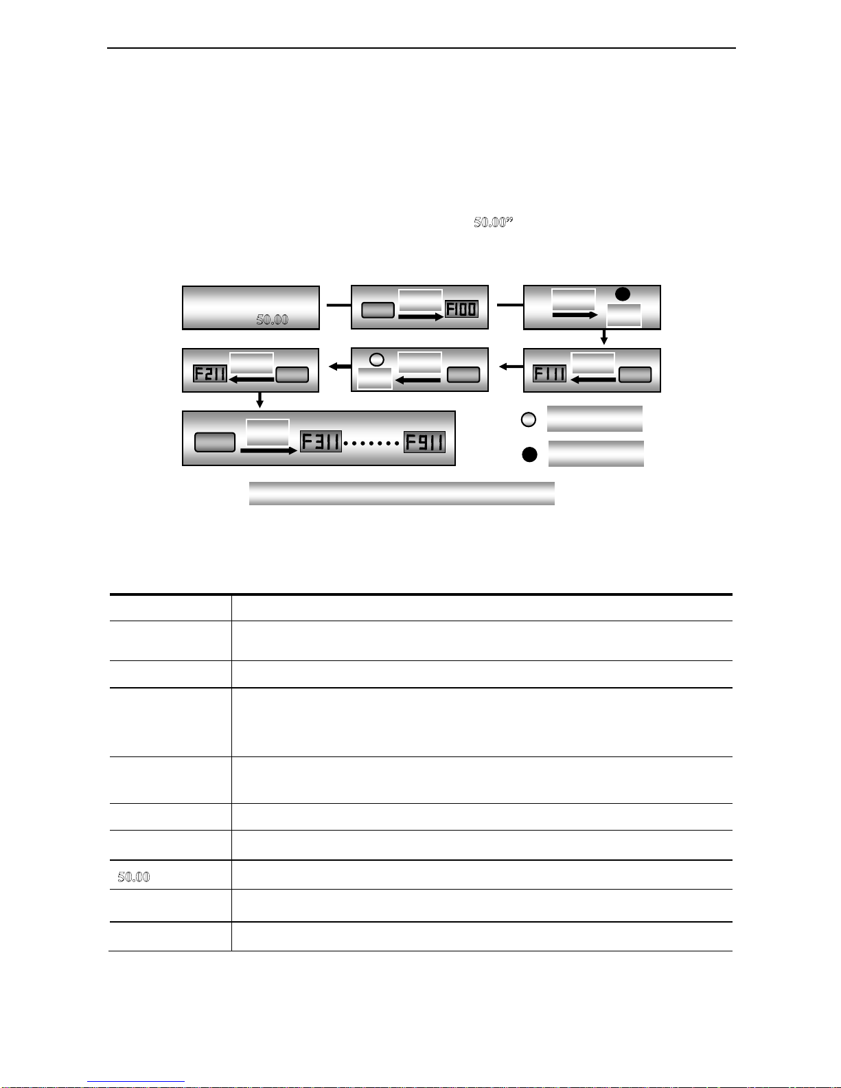
e.g. when function code shows F111 and DGT indicatoris on, press “▲”/ “▼” key, function code will keep
increasing or decreasing by degrees within F100~F160; press “stop/reset” key again, DGT indicator will be
off. When pressing “▲”/ “▼” key, function codes will change circularly among the 10 code-groups, like
F211, F311…FA11, F111…, Refer to Fig 2-2 (The sparkling “ is indicated the corresponding target
frequency values).
2.6 Panel Display
Table 2-4 Items and Remarks Displayed on the Panel
Items
Remarks
HF-0
This Item will be displayed when you press “Fun” in stopping status, which indicates jogging
operation is valid. But HF -0 will be displayed only after you change the value of F132.
-HF-
It stands for resetting process and will display target frequency after reset.
OC,OC1,OE,
OL1,OL2,OH,
LU,PF0,PF1
Fault code, indicating “hardware over-current”, “software over-current”,
“over-voltage”, “inverter over-load”, “motor over-load”“over-heat”, “under-voltage
for input”, “out-phase for input” ,” and “out-phase for output” respectively.
ESP
During two-line/three line running mode, “stop/reset” key is pressed or external emergency stop
terminal is closed, ESP will be displayed.
F152
Function code (parameter code).
10.00
Indicating inverter‟s current running frequency (or rotate speed) and parameter setting values, etc.
Sparkling in stopping status to display target frequency.
0.
Holding time when changing the running direction. When “Stop” or “Free Stop” command is executed,
the holding time can be canceled
A100、U100
Output current (100A) and output voltage (100V). Keep one digit of decimal when current is below
100A.
Enter correct user‟s
password (currently
showing )
Fun
Display
Display
DGT
Stop/Reset
Display
DGT
▲
Display
▲
Display
▲
Display
DGT Off
DGT On
Fig 2-2 Swtich over in a Code Group or between Different Code-Groups
TT100
·11·
III. Installation & Connection
3.1 Installation
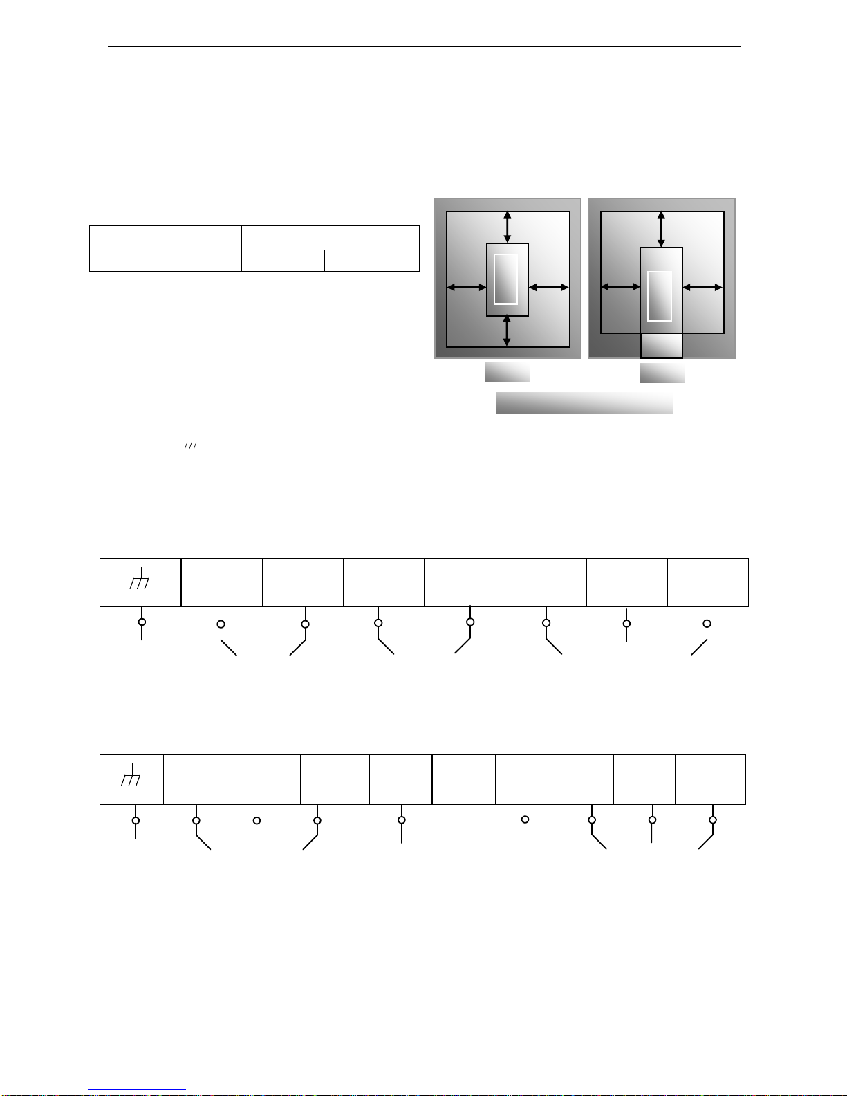
Inverter should be installed vertically, as shown in Fig 3-1. Sufficient ventilation space should be ensured in
its surrounding. Clearance dimensions (recommended) are available from Table 3-1 for installing the
inverter.
Table 3-1 Clearance Dimensions
Inverter Model
Clearance Dimensions
Hanging (≤ 15 kw)
A≥150mm
B≥50mm
3.2 Connection
In case of 3-phase input, connect R/L1,
S/L2 and T/L3 terminals (L1/R and
L2/S terminals for single-phase) with
power source from network and
/PE/E to earthing, U, V and W terminals to motor.
Motor shall have to be ground connected. Orelse electrified motor causes interference.
For inverter power lower than 15kw, braking cell is also built-in. If the load inertia is moderate,
it is Ok to only connect braking resistance.
Power terminals sketch of inverter with single-phase 230V 0.2~0.75KW.
L1
L2 P B U V
W
Power terminals sketch of inverter with single-phase 230V 1.5~2.2KW and three-phase
400V 0.75KW~15KW.
L1/R
L2/S
L3/T
P
-
B U V
W
Note: power terminals L1/R, L2/S of single-phase 230V 1.5KW and 2.2KW are connected
to 230V of power grid; L3/T is not connected.
The inverters below 11kw have no the terminal “-”.
Grounding
Input ~400V
For braking resistor
Output
Grounding
Input ~230V
For braking resistor
Output
A
B B
A
Inverter
C
D D
Inverter
Trench
Hanging
Cabinet
Fig 3-1 Installation Sketch
TT100
·12·
(The figure is only sketch, terminals order of practical products may be different from the above-mentioned
figure.)
Introduction of terminals of power loop
Terminals
Terminal
Marking
Terminal Function Description
Power Input
Terminal
R/L1, S/L2,
T/L3
Input terminals of three-phase 400V AC voltage (R/L1 and S/L2
terminals for single-phase)
Output Terminal
U, V, W
Inverter power output terminal, connected to motor.
Grounding
Terminal
/PE/E
Inverter grounding terminal.
Rest Terminal
P, B
External braking resistor (Note: no Terminals P or B for inverter
without built-in braking unit).
P+、-(N)
DC bus-line output
P、-(N)
Externally connected to braking unit
P connected to input terminal “P” or “DC+” of braking unit, -(N)
connected to input terminal of braking unit “N” or “DC-”.
P, P+
Externally connected to DC reactor
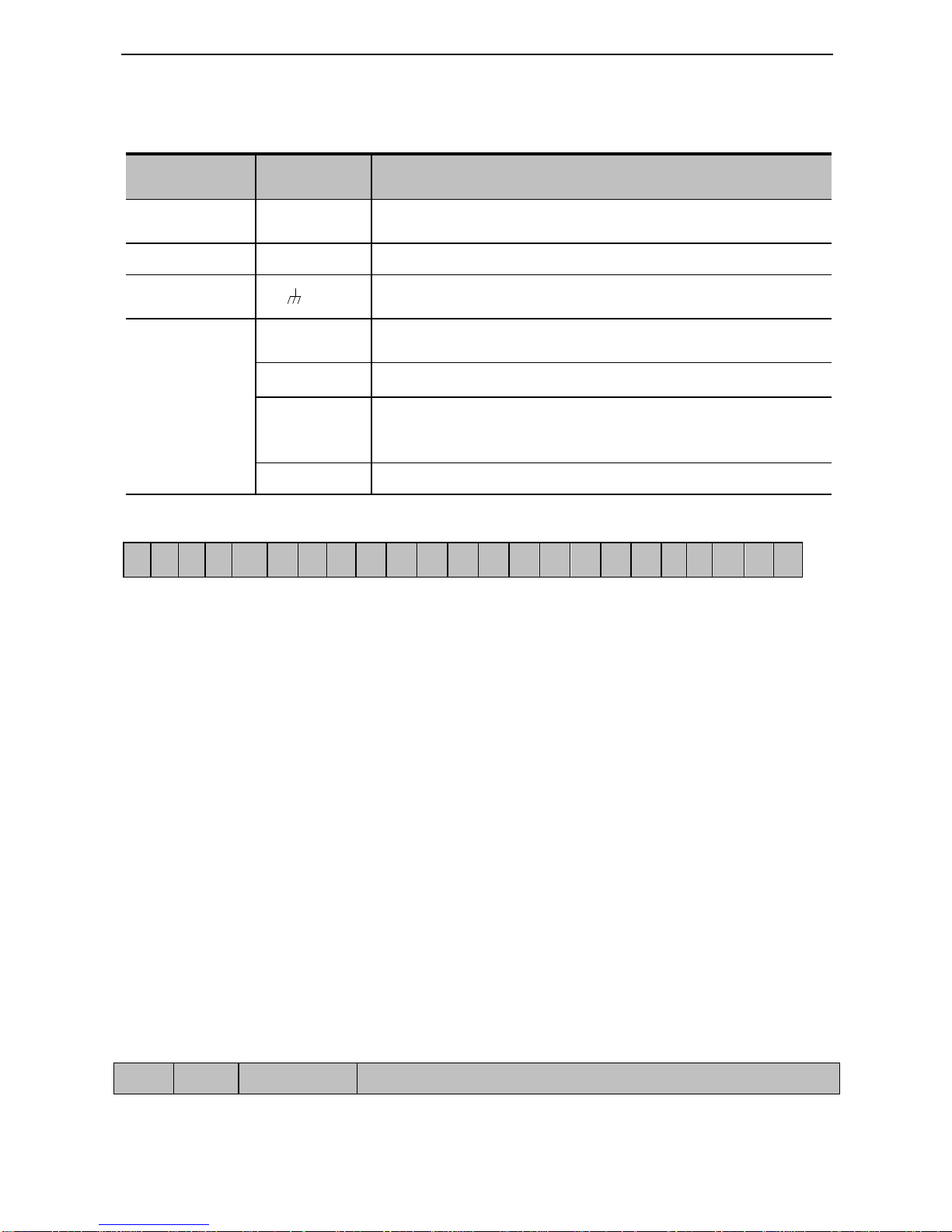
Wiring for control loop as follows:
A+
B-
TA
TB
TC
DO1
DO2
24V
CM
OP1
OP2
OP3
OP4
OP5
OP6
OP7
OP8
10V
AI1
AI2
GND
AO1
AO2
Note: 15KW inverters and below 15KW have no A+、B- , DO2 and OP7, OP8 control terminal.
3.3 Functions of control terminals
The key to operate the inverter is to operate the control terminals correctly and flexibly. Certainly, the control
terminals are not operated separately, and they should match corresponding settings of parameters. This
chapter describes basic functions of the control terminals. The users may operate the control terminals by
combining relevant contents hereafter about “Defined Functions of the Terminals”.
Table 4-3 Functions of Control Terminals
Type
Description
Function

TT100
·13·
DO1
Output
signal
Multifunctional
output terminal 1
When the token function is valid, the value
between this terminal and CM is 0V; when the
inverter is stopped, the value is 24V.
The functions of output
terminals shall be defined
per manufacturer‟s value.
Their initial state may be
changed through
changing function codes.
DO2
Note
Multifunctional
output terminal 2
When the token function is valid, the value
between this terminal and CM is 0V; when the
inverter is stopped, the value is 24V.
TA
Relay contact
TC is a common point, TB-TC are normally
closed contacts, TA-TC are normally open
contacts. The contact capacity of 15kw and below
15kw inverter is 10A/125VAC、5A/250VAC、
5A/30VDC, contact capacity of bove 15kw is
12A/125VAC、7A/250VAC、7A/30VDC.
TB
TC
AO1
Running
frequency
It is connected with frequency meter or speedometer externally, and its
minus pole is connected with GND. See F423~F426 for details,.
AO2
Current display
It is connected with ammeter externally, and its minus pole is connected
with GND. See F427~F430 for details
10V
Analog
power
supply
Self contained
power supply
Internal 10V self-contained power supply of the inverter provides power
to the inverter. When used externally, it can only be used as the power
supply for voltage control signal, with current restricted below 20mA.
AI1
Input
Signal
Voltage analog
input port
When analog speed control is adopted, the voltage signal is input through
this terminal. The range of voltage input is 0~10V, grounding: GND.
When potentiometer speed control is adopted, this terminal is connected
with center tap, earth wire to be connected to GND.
AI2
Voltage / Current
analog input port
When analog speed control is adopted, the voltage or current signal is
input through this terminal. The range of voltage input is 0~5V or 0~10V
and the current input is 0~20mA, input resistor is 500Ω, grounding:
GND. If the input is 4~20mA, it can be realized through adjusting
parameter F406=2. The voltage or current signal can be chosen by coding
switch. See table 4-2 and 4-3 for details, the current channel (0-20mA) is
chosen before delivery.
GND
Self-contained
Power
supply Ground
Ground terminal of external control signal (voltage control signal or
current source control signal) is also the ground of 10V power supply of
this inverter.
24V
Power
supply
Control power
supply
Power: 24±1.5V, grounding: CM; current is restricted below 50mA for
external use.
OP1
Digital
input
control
terminal
Jogging terminal
When this terminal is in the valid state, the
inverter will have jogging running. The
jogging function of this terminal is valid
under both at stopped and running status. This
terminal can also be used as high-speed pulse
input port. The max frequency is 50K.
The functions of input
terminals shall be defined
per manufacturer‟s value.
Other functions can also
be defined by changing
function codes.
OP2
External
Emergency Stop
When this terminal is in the valid state, “ESP”
malfunction signal will be displayed.
OP3
“FWD” Terminal
When this terminal is in the valid state,
inverter will run forward.
OP4
“REV” Terminal
When this terminal is in the valid state,
inverter will run reversely.
OP5
Reset terminal
Make this terminal valid under fault status to
reset the inverter.
OP6
Free-stop
Make this terminal valid during running can
TT100
·14·
realize free stop.
OP7
Running terminal
When this terminal is in the valid state,
inverter will run by the acceleration time.
OP8
Stop terminal
Make this terminal valid during running can
realize stop by the deceleration time.
CM
Common
port
Grounding of
control power
supply
The grounding of 24V power supply and other control signals.
A+
note
485
communic
ation
terminals
Positive polarity of
differential signal
Standard: TIA/EIA-485(RS-485)
Communication protocol: Modbus
Communication rate: 1200/2400/4800/9600/19200/38400/57600bps
B-
note
Negative polarity of
Differential signal
Note : 15KW inverters and below 15KW have no A+, B- , DO2 and OP7, OP8 control terminal.
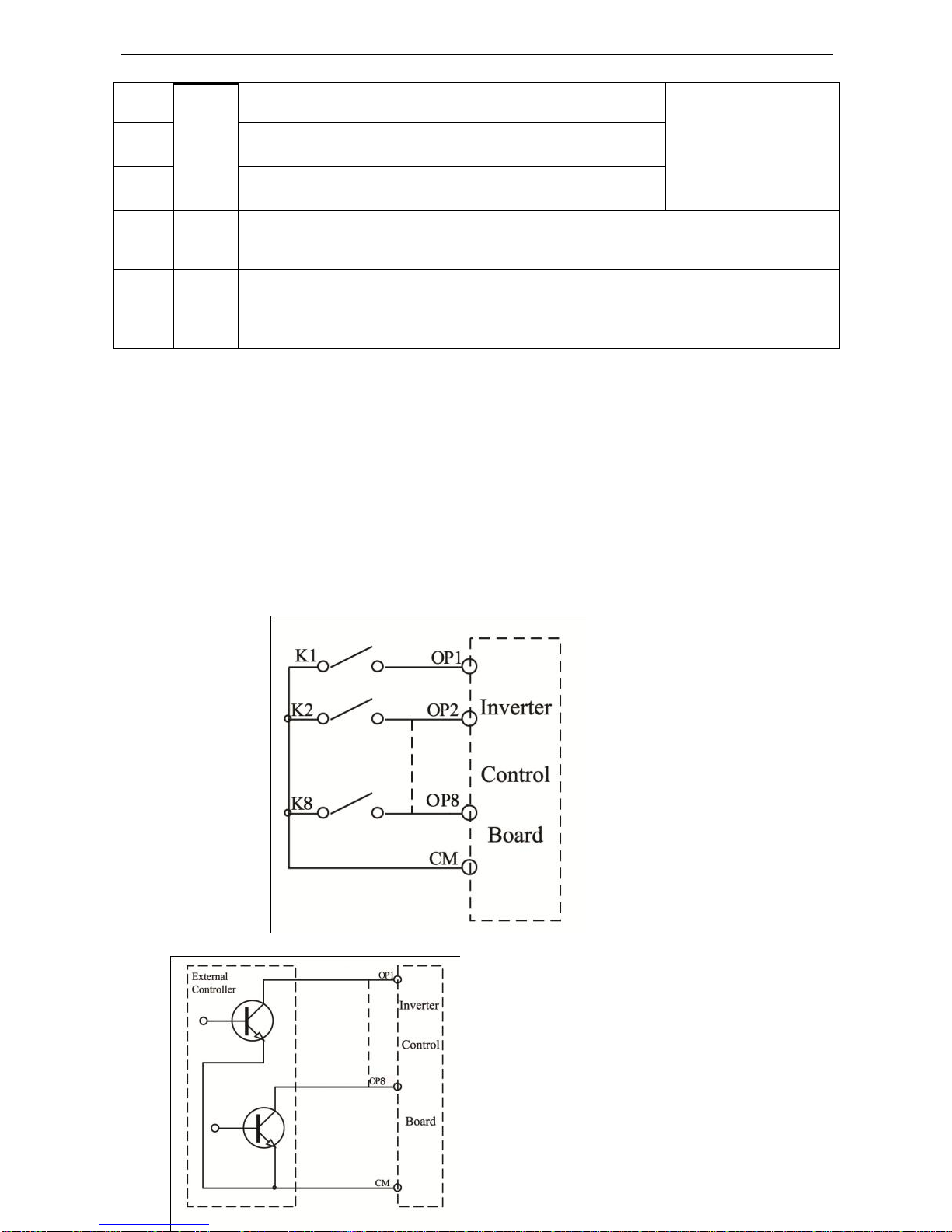
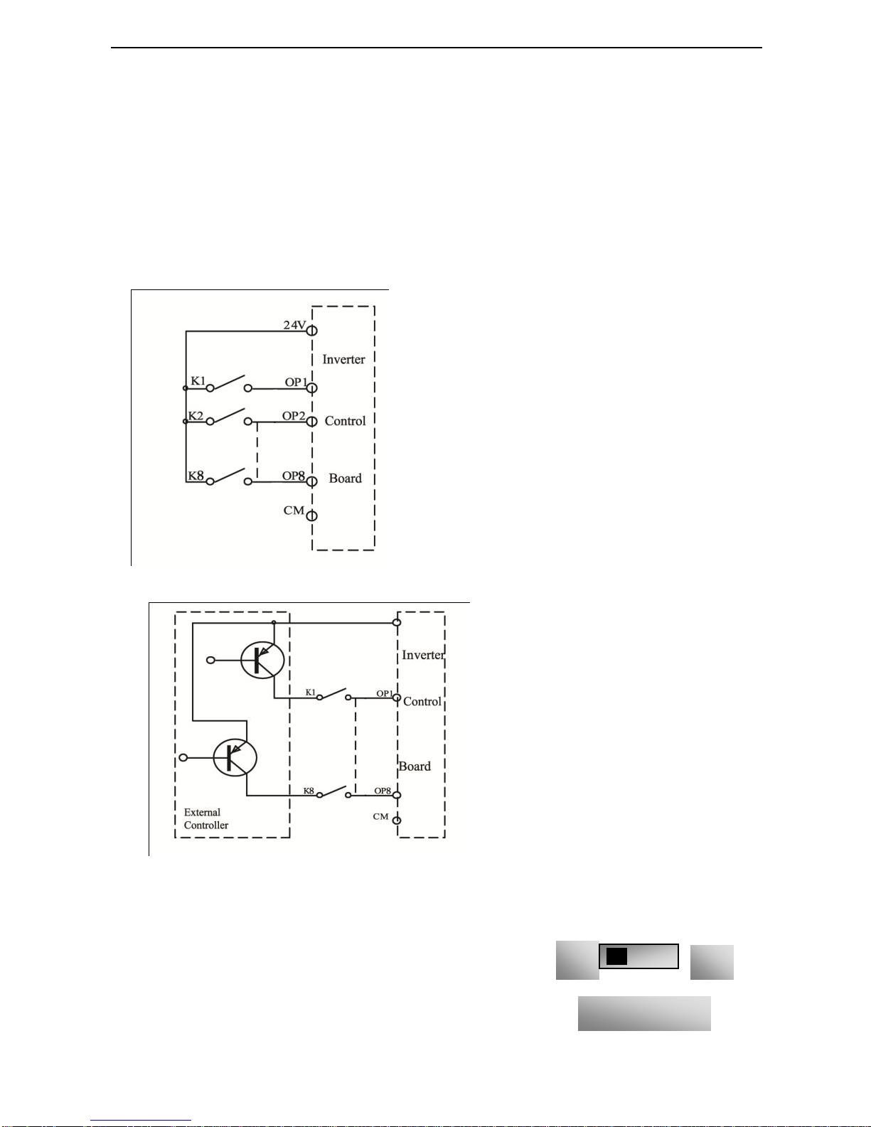
Wiring for digital input terminals:
Generally, shield cable is adopted and wiring distance should be as short as possible. When active
signal is adopted, it is necessary to take filter measures to prevent power supply interference. Mode of
contact control is recommended.
Digital input terminals are only connected by source electrode (NPN mode) or by drain electrode (PNP
mode). If NPN mode is adopted, please turn the toggle switch to the end of “NPN”.
Wiring for control terminals as follows:
1. Wiring for positive source electrode (NPN mode).
2. Wiring for active source electrode (NPN
mode)
TT100
·15·
NPN
PNP
Fig 3-2 Toggle Switch J7
If digital input control terminals are connected by drain electrode, please turn the toggle switch to the
end of “PNP”. Wiring for control terminals as follows:
3. Wiring for positive drain electrode (PNP mode)
4. Wiring for active drain electrode (PNP mode)
Wiring by source electrode is a mode most
in use at present. Wiring for control terminal is connected by source electrode before delivery, user
should choose wiring mode according to requirement.
Instructions of choosing NPN mode or PNP mode:
1. There is a toggle switch J7 near to control terminals. Please refer to
Fig 3-2.
2. When turning J7 to “NPN”, OP terminal is connected to CM.
When turning J7 to “PNP”, OP terminal is connected to 24V.
TT100
·16·
3. J7 is on the back of control PCB of single-phase 0.2KW-0.75KW.
3.4 Wiring Recommended
Inverter Model
Lead Section Area(mm2)
TT100-0002S2
1.0
TT100-0004S2
1.5
TT100-0007S2
2.5
TT100-0015S2
2.5
TT100-0022S2
4.0
TT100-0007T3
1.5
TT100-0015T3
2.5
TT100-0022T3
2.5
TT100-0037T3
2.5
TT100-0040T3
2.5
TT100-0055T3
4.0
TT100-0075T3
4.0
TT100-0110T3
6.0
TT100-0150T3
10
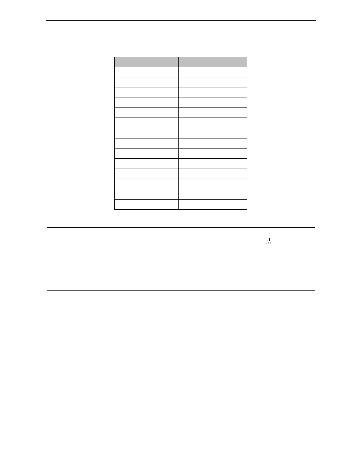
3.5 Lead section area of protect conductor (grounding wire)
Lead section area S of U,V,W (mm2)
Minimum lead section area S of /PE/E (mm2)
S16
16<S35
35<S
S
16
S/2
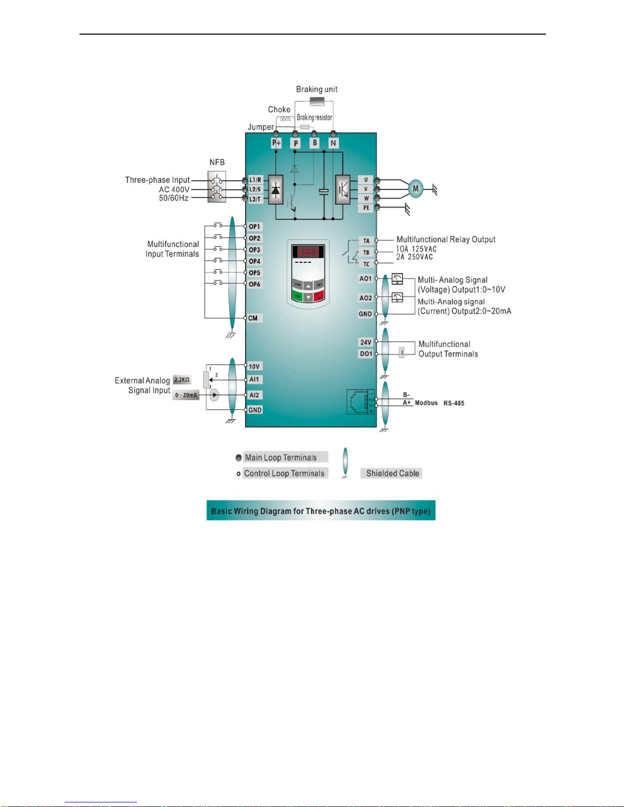
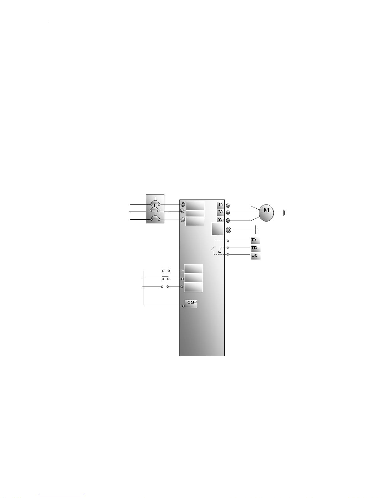
3.6 Overall Connection and “Three- Line” Connection
* Refer to next figure for overall connection sketch for TT100 series inverters. Wiring mode is available for various
terminals whereas not every terminal needs connection when applied.
TT100
·17·
Note:
1. Please only connect power terminals L1/R and L2/S with power grid for single-phase inverters.
2. Remote-control panels and 485 communication port should be connected with 4 core telephone wire. They must not
be used at the same time.
3. 485 communication port has built-in standard MODBUS communication protocol. Communication port is on the left
side of inverter. The sequence from top to down is 5V power, B-terminal, A+ terminal and GND terminal.
4. Inverter above 15kw has 8 multifunctional input terminals OP1~OP8, 15kw inverter and below 15kw has 6
multifunctional input terminals OP1~OP6.
5. The contact capacity of 15kw and below 15kw inverter is 10A/125VAC、5A/250VAC、5A/30VDC.
IV. Operation and Simple Running

TT100
·18·
This chapter defines and interprets the terms and nouns describing the control, running and status of the
inverter. Please read it carefully. It will be helpful to your correct operation.
4.1 Control mode
Control mode of TT100 inverter is V/F control.
4.2 Mode of torque compensation
Linear compensation (F137=0); Square compensation (F137=1); User-defined multipoint compensation
(F137=2); Auto torque compensation (F137=3)
4.3 Mode of frequency setting
Please refer to F203~F207 for the method for setting the running frequency of the TT100 inverter.
4.4 Mode of controlling for running command
The channel for inverter to receive control commands (including start, stop and jogging, etc) contains three
modes: 1. Keypad (keypad panel) control; 2. External terminal control; 3. Modbus control.
The modes of control command can be selected through the function codes F200 and F201.
4.5 Operating status of inverter
When the inverter is powered on, it may have four kinds of operating status: stopped status, programming
status, running status, and fault alarm status. They are described in the following:
4.5.1 Stopped status
If re-energize the inverter (if “self-startup after being powered on” is not set) or decelerate the inverter to
stop, the inverter is at the stopping status until receiving control command. At this moment, the running
status indicator on the keypad goes off, and the display shows the display status before power down.
4.5.2 Programming status
Through keypad panel, the inverter can be switched to the status that can read or change the function
code parameters. Such a status is the programming status.
There are numbers of function parameters in the inverter. By changing these parameters, the user can
realize different control modes.
4.5.3 Running status
The inverter at the stopped status or fault-free status will enter running status after having received
operation command.
The running indicator on keypad panel lights up under normal running status.
4.5.4 Fault alarm status
The status under which the inverter has a fault and the fault code is displayed.
Fault codes mainly include: OC, OE, OL1, OL2, OH, LU, PF1, representing “over current”, “over
voltage”, “inverter overload”, “motor overload”, “overheat”, “input undervoltage”, “input out-phase”, and
respectively.
For trouble shooting, please refer to Appendix I to this manual, “Trouble Shooting”.
4.6 Keypad panel and operation method
Keypad panel (keypad) is a standard part for configuration of TT100 inverter. Through keypad panel, the
user may carry out parameter setting, status monitoring and operation control over the inverter. Both keypad
panel and display screen are arranged on the keypad controller, which mainly consists of three sections: data
display section, status indicating section, and keypad operating section. There are two types of keypad
controller (with potentiometer or without potentiometer) for inverter. For details, please refer to Chapter II of
this manual, “Keypad panel”.
It is necessary to know the functions and how to use the keypad panel. Please read this manual carefully

TT100
·19·
before operation.
4.6.1 Method of operating the keypad panel
(1) Operation process of setting the parameters through keypad panel
A three-level menu structure is adopted for setting the parameters through keypad panel of inverter, which
enables convenient and quick searching and changing of function code parameters.
Three-level menu: Function code group (first-level menu) → Function code (second-level menu) → Set
value of each function code (third-level menu).
(2) Setting the parameters
Setting the parameters correctly is a precondition to give full play of inverter performance. The following
is the introduction on how to set the parameters through keypad panel.
Operating procedures:
① Press the “Fun” key, to enter programming menu.
② Press the key “Stop/Reset”, the DGT lamp goes out. Press ▲ and ▼, the function code will change
within the function code group. The first number behind F displayed on the panel is 1, in other
words, it displays F1××at this moment.
③ Press the key “Stop/Reset” again, the DGT lamp lights up, and the function code will change within
the code group. Press ▲ and ▼ to change the function code to F113; press the “Set” key to display
50.00; while press ▲ and ▼ to change to the need frequency.
④ Press the “Set” key to complete the change.
4.6.2 Switching and displaying of status parameters
Under stopped status or running status, the LED digitron of inverter can display status parameters of the
inverter. Actual parameters displayed can be selected and set through function codes F131 and F132.
Through the “Fun” key, it can switch over repeatedly and display the parameters of stopped status or running
status. The followings are the description of operation method of displaying the parameters under stopped
status and running status.
(1) Switching of the parameters displayed under stopped status
Under stopped status, inverter has five parameters of stopped status, which can be switched over
repeatedly and displayed with the keys “Fun” and “Stop/Reset”. These parameters are displaying: keypad
jogging, target rotary speed, PN voltage, PID feedback value, and temperature. Please refer to the
description of function code F132.
(2) Switching of the parameters displayed under running status
Under running status, eight parameters of running status can be switched over repeatedly and displayed
with the keys “Fun”. These parameters are displaying : output rotary speed, output current, output voltage,
PN voltage, PID feedback value, temperature, count value and linear speed. Please refer to the description
of function code F131.
4.7 Operation process of measuring motor stator resistance parameters
The user shall input the parameters accurately as indicated on the nameplate of the motor prior to selecting
auto torque compensation (F137=3). Inverter will match standard motor stator resistance parameters
according to these parameters indicated on the nameplate. To achieve better control performance, the user
may start the inverter to measure the motor stator resistance parameters, so as to obtain accurate parameters
of the motor controlled.
The stator resistance parameters of the motor can be measured through function code F800.
For example: If the parameters indicated on the nameplate of the motor controlled are as follows: numbers of
motor poles are 4; rated power is 7.5KW; rated voltage is 400V; rated current is 15.4A; rated frequency is
50.00HZ; and rated rotary speed is 1440rpm, operation process of measuring the parameters shall be done as
described in the following:
1. In accordance with the above motor parameters, set the values of F801 to F805 correctly: set the value of
F801 = 7.5, F802 = 400, F803 =15.4, F804 = 4, and F805 = 1440 respectively.

TT100
·20·
2. In order to ensure dynamic control performance of the inverter, set F800=1, i.e. select stator resistance
parameter measurement. Press the “Run” key on the keypad, and the inverter will display “TEST”, after
few seconds, self-checking is completed, motor stator resistance parameters will be stored in function code
F806, and F800 will turn to 0 automatically.
4.8 Operation process of simple running
Table 4-1 Brief Introduction to Inverter Operation Process
Process
Operation
Reference
Installation and
operation environment
Install the inverter at a location meeting the technical
specifications and requirements of the product. Mainly take into
consideration the environment conditions (temperature, humidity,
etc) and heat radiation of the inverter, to check whether they can
satisfy the requirements.
See Chapters I, II,
III.
Wiring of the inverter
Wiring of input and output terminals of the main circuit; wiring
of grounding; wiring of switching value control terminal,
analog terminal and communication interface, etc.
See Chapter III.
Checking before
getting energized
Make sure that the voltage of input power supply is correct; the input
power supply loop is connected with a breaker; the inverter has been
grounded correctly and reliably; the power cable is connected to the
power supply input terminals of inverter correctly (R/L1, S/L2 terminals
for single-phase power grid, and R/L1, S/L2, and T/L3 for three-phase
power grid); the output terminals U, V, and W of the inverter are
connected to the motor correctly; the wiring of control terminals is
correct; all the external switches are preset correctly; and the motor is
under no load (the mechanical load is disconnected from the motor).
See Chapters I~
III
Checking immediately
after energized
Check if there is any abnormal sound, fuming or foreign flavor
with the inverter. Make sure that the display of keypad panel is
normal, without any fault alarm message. In case of any
abnormality, switch off the power supply immediately.
See Appendix 1
and Appendix 2.
Inputting the parameters
indicated on the motor‟s
nameplate correctly, and
measuring the motor stator
resistance parameters.
Make sure to input the parameters indicated on the motor
nameplate correctly, and measure the motor stator resistance
parameters to get the best control performance.
See description of
parameter group
F800~F830
Setting running control
parameters
Set the parameters of the inverter and the motor correctly, which
mainly include target frequency, upper and lower frequency limits,
acceleration/deceleration time, and direction control command, etc.
The user can select corresponding running control mode according
to actual applications.
See description of
parameter group.
Checking under
no load
With the motor under no load, start the inverter with the keypad or
control terminal. Check and confirm running status of the drive
system. Motor‟s status: stable running, normal running, correct
rotary direction, normal acceleration/deceleration process, free from
abnormal vibration, abnormal noise and foreign flavor. Inverter‟
status: normal display of the data on keypad panel, normal running
of the fan, normal acting sequence of the relay, free from the
abnormalities like vibration or noise. In case of any abnormality,
stop and check the inverter immediately.
See Chapter Ⅳ.
TT100
·21·
Checking under with
load
After successful test run under no load, connect the load of
drive system properly. Start the inverter with the keypad or
control terminal, and increase the load gradually. When the load
is increased to 50% and 100%, keep the inverter run for a
period respectively, to check if the system is running normally.
Carry out overall inspection over the inverter during running, to
check if there is any abnormality. In case of any abnormality,
stop and check the inverter immediately.
Checking during
running
Check if the motor is running stably, if the rotary direction of
the motor is correct, if there is any abnormal vibration or noise
when the motor is running, if the acceleration/deceleration
process of the motor is stable, if the output status of the inverter
and the display of keypad panel is correct, if the blower fan is
run normally, and if there is any abnormal vibration or noise. In
case of any abnormality, stop the inverter immediately, and
check it after switching off the power supply.
4.9 Illustration of basic operation
Illustration of inverter basic operation: we hereafter show various basic control operation processes by taking
a 7.5kW inverter that drives a 7.5kW three-phase asynchronous AC motor as an example.
The parameters indicated on the nameplate of the motor are as follows: 4 poles; rated power, 7.5KW; rated
voltage, 400V; rated current, 15.4A; rated frequency 50.00HZ; and rated rotary speed, 1440rpm.
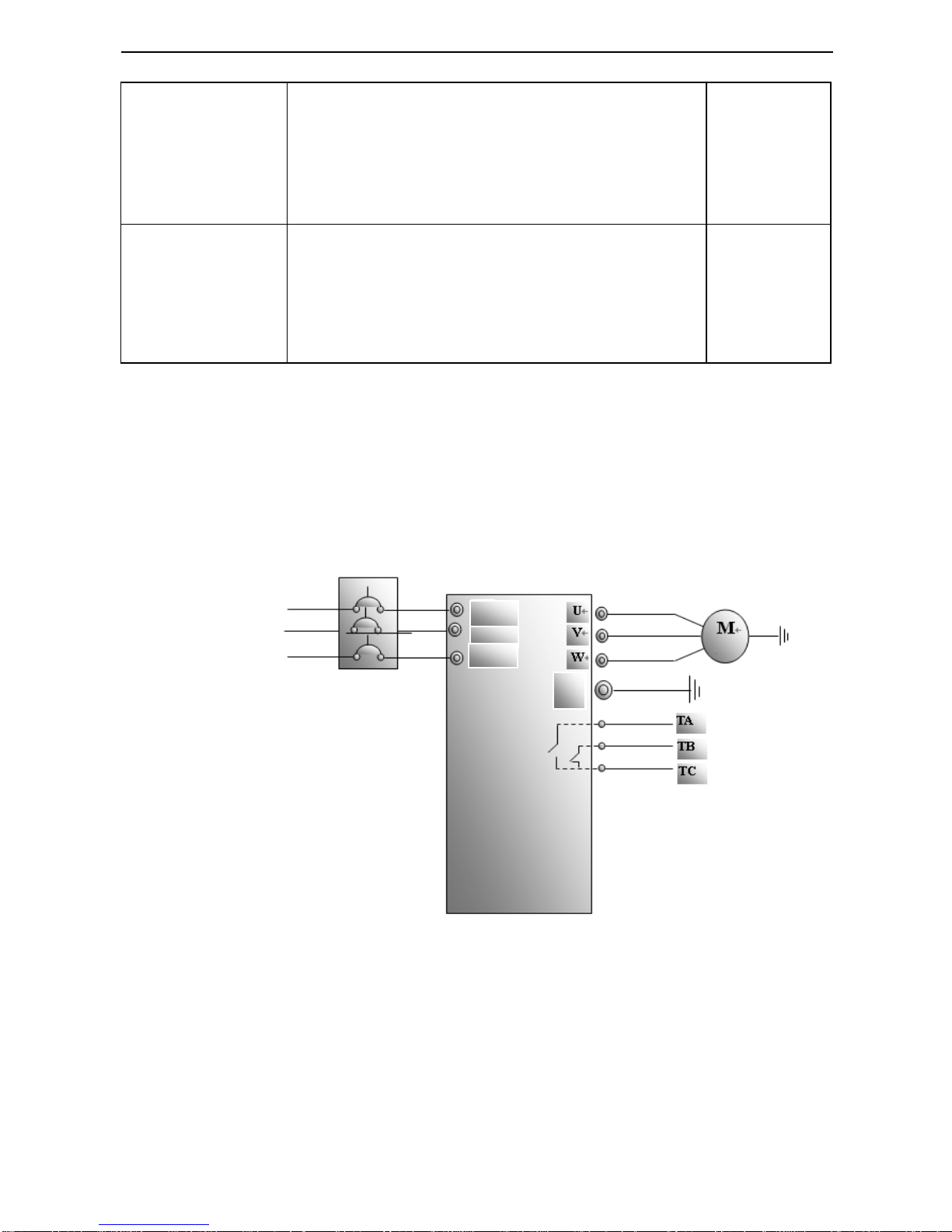
4.9.1 Operation processes of frequency setting, start, forward running and stop with keypad
panel
(1) Connect the wires in accordance with Figure 4-1. After having checked the wiring successfully,
switch on the air switch, and power on the inverter.
Figure 4-1 Wiring Diagram 1
(2) Press the “Fun” key, to enter the programming menu.
(3) Measure the parameters of motor stator resistance parameter
① Enter F801 parameter and set rated power of the motor to 7.5kW;
② Enter F802 parameter and set rated voltage of the motor to 400V;
③ Enter F803 parameter and set rated current of the motor to 15.4A;
④ Enter F804 parameter and set number of poles of the motor to 4;
⑤ Enter F805 parameter and set rated rotary speed of the motor to 1440 rpm;
PE
S/L2
R/L1
T/L3
AC 400V
TT100
·22·
⑥ Enter F800 parameter and set it to 1 to allow measuring the parameter of the motor
⑦ Press the “Run” key, to measure the parameters of the motor. After completion of the measurement,
and relevant parameters will be stored in F806. For the details of measurement of motor parameters,
please refer to “Operation process of measuring the motor parameters” in this manual and Chapter
XII of this manual.
(4) Set functional parameters of the inverter:
①Enter F203 parameter and set it to 0;
②Enter F111 parameter and set the frequency to 50.00Hz;
③Enter F200 parameter and set it to 0; select the mode of start as keypad control;
④Enter F201 parameter and set it to 0; select the mode of stop as keypad control;
⑤Enter F202 parameter and set it to 0; select forward locking.
(5) Press the “Run” key, to start the inverter;
(6) During running, current frequency of the inverter can be changed by pressing ▲ or ▼;
(7) Press the “Stop/Reset” key once, the motor will decelerate until it stops running;
(8) Switch off the air switch, and power off the inverter.
4.9.2 Operation process of setting the frequency with keypad panel, and starting,
forward and reverse running, and stopping inverter through control terminals
(1) Connect the wires in accordance with Figure 4-2. After having checked the wiring successfully,
switch on the air switch, and power on the inverter;
Figure 4-2 Wiring Diagram 2
(2) Press the “Fun” key, to enter the programming menu.
(3) Study the parameters of the motor: the operation process is the same as that of example 1.
(4) Set functional parameters of the inverter:
①Enter F203 parameter and set it to 0; select the mode of frequency setting to digital given memory;
②Enter F111 parameter and set the frequency to 50.00Hz;
③Enter F208 parameter and set it to 1; select two-line control mode 1 (Note: when F208 ≠0, F200,
F201 and F202 will be invalid.)
(5) Close the switch OP3, the inverter starts forward running;
(6) During running, current frequency of the inverter can be changed by pressing ▲ or ▼;
PE
OP3
OP4
OP6
S/L2
R/L1
T/L3
AC400V

TT100
·23·
(7) During running, switch off the switch OP3, then close the switch OP4, the running direction of the
motor will be changed (Note: The user should set the dead time of forward and reverse running F120 on
the basis of the load. If it was too short, OC protection of the inverter may occur.)
(8) Switch off the switches OP3 and OP4, the motor will decelerate until it stops running;
(9) Switch off the air switch, and power off the inverter.
4.9.3 Operation process of jogging operation with keypad panel
(1) Connect the wires in accordance with Figure 4-1. After having checked the wiring successfully,
switch on the air switch, and power on the inverter;
(2) Press the “Fun” key, to enter the programming menu.
(3) Study the parameters of the motor: the operation process is the same as that of example 1.
(4) Set functional parameters of the inverter:
① Enter F132 parameter and set it to 1; select keypad jogging;
② Enter F200 parameter and set it to 0; select the mode of running command control as keypad operation;
③ Enter F124 parameter, and set the jogging operation frequency to 5.00Hz;
④ Enter F125 parameter, and set the jogging acceleration time to 30S;
⑤ Enter F126 parameter, and set the jogging deceleration time to 30S;
⑥ Enter F202 parameter, and set it to 0; select forward running locking.
(5) Press and hold the “Run” key until the motor is accelerated to the jogging frequency, and maintain the
status of jogging operation.
(6) Release the “Run” key. The motor will decelerate until jogging operation is stopped;
(7) Switch off the air switch, and power off the inverter.
4.9.4 Operation process of setting the frequency with analog terminal and controlling
the operation with control terminals
(1) Connect the wires in accordance with Figure 4-3. After having checked the wiring successfully,
switch on the air switch, and power on the inverter. Note: 2K~5K potentiometer may be adopted for
setting external analog signals. For the cases with higher requirements for precision, please adopt precise
multiturn potentiometer, and adopt shielded wire for the wire connection, with near end of the shielding
layer grounded reliably.
Figure 4-3 Wiring Diagram 3
+10V
AC400V
R/L1
T/L3
S/L2
OP3
OP6
OP4

TT100
·24·
(2) Press the “Fun” key, to enter the programming menu.
(3) Study the parameters of the motor: the operation process is the same as that of example 1.
(4) Set functional parameters of the inverter:
① Enter F203 parameter, and set it to 1; select the mode of frequency setting of analog AI1, 0~10V
voltage terminal;
② Enter F208 parameter, and set it to 1; select direction terminal (set OP6 to free stop, set OP3 to
forward running, set OP4 to reverse running) to control running;
(5) There is a red two-digit coding switch SW1 near the control terminal block of
15 KW inverter and below 15kw , as shown in Figure 4-4. The function of coding
switch is to select the voltage signal (0~5V/0~10V) or current signal of analog
input terminal AI2, current channel is default. In actual application, select the
analog input channel through F203. Turn switches 1 to ON and 2 to ON as
illustrated in the figure, and select 0~20mA current speed control. Another
switches states and mode of control speed are as table 4-2.
(6) Close the switch OP3, the motor starts forward running;
(7) The potentiometer can be adjusted and set during running, and the current setting frequency of the
inverter can be changed;
(8) During running, switch off the switch OP3, then, close OP4, the running direction of the motor will be changed;
(9) Switch off the switches OP3 and OP4, the motor will decelerate until it stops running;
(10) Switch off the air switch, and power off the inverter.
Table 4-2 The Setting of Coding Switch and Parameters in the Mode of Analog Speed Control
Table 4-3
V. Function Parameters
5.1 Basic parameters
F100 User‟s Password
Setting range: 0~9999
Mfr‟s value: 8
Set F203 to 2, to select channel AI2
Coding Switch 1
Coding Switch 2
Mode of Speed Control
OFF
OFF
0~5V voltage
OFF
ON
0~10V voltage
ON
ON
0~20mA current
ON refers to switching the coding switch to the top.
OFF refers to switching the coding switch to the bottom.
Set F203 to 1, to select channel AI1
Set F203 to 2, to select channel AI2
Coding Switch 1
Coding Switch 3
Analog signal range
Coding Switch 2
Coding Switch 4
Analog signal range
OFF
OFF
0~5V voltage
OFF
OFF
0~5V voltage
OFF
ON
0~10V voltage
OFF
ON
0~10V voltage
ON
ON
0~20mA current
ON
ON
0~20mA current
ON refers to switching the coding switch to the top.
OFF refers to switching the coding switch to the bottom.
ON
2
1

TT100
·25·
·When F107=1 with valid password, the user must enter correct user‟s password after power on or fault reset
if you intend to change parameters. Otherwise, parameter setting will not be possible, and a prompt “Err1”
will be displayed.
Relating function code: F107 Password valid or not
F108 Setting user‟s password
F102 Inverter‟s Rated Current (A)
Setting range: 1.0~800.0
Mfr‟s value: Subject to inverter model
F103 Inverter Power (KW)
Setting range: 0.2~500.0
Mfr‟s value: Subject to inverter model
· Rated current and rated power can only be checked but cannot be modified.
Softward Edition No. can only be checked but cannot be modified.
F107 Password Valid or Not
Setting range: 0: invalid; 1: valid
Mfr‟s value: 0
F108 Setting User‟s Password
Setting range: 0~9999
Mfr‟s value: 8
·When F107 is set to 0, the function codes can be changed without inputting the password. When F107 is set
to 1, the function codes can be changed only after inputting the user‟s password by F100.
·The user can change “User‟s Password”. The operation process is the same as those of changing other
parameters.
· Input the value of F108 into F100, and the user‟s password can be unlocked.
Note: When password protection is valid, and if the user‟s password is not entered, F108 will display 0.
F109 Starting Frequency (Hz)
Setting range: 0.00~10.00
Mfr‟s value: 0.00 Hz
F110 Holding Time of Starting Frequency (S)
Setting range: 0.0~10.0
Mfr‟s value: 0.0
·The inverter begins to run from the starting frequency. If the target frequency is lower than starting
frequency, F109 is invalid.
·The inverter begins to run from the starting frequency. After it keeps running at the starting frequency for
the time as set in F110, it will accelerate to target frequency. The holding time is not included in
acceleration/deceleration time.
·Starting frequency is not limited by the Min frequency set by F112. If the starting frequency set by F109 is
lower than Min frequency set by F112, inverter will start according to the setting parameters set by F109 and
F110. After inverter starts and runs normally, the frequency will be limited by frequency set by F111 and
F112.
·Starting frequency should be lower than Max frequency set by F111.
·If starting frequency is lower than target frequency set by F113, starting frequency will be invalid.
F111 Max Frequency (Hz)
Setting range: F113~650.0
Mfr‟s value: 50.00Hz
F112 Min Frequency (Hz)
Setting range: 0.00~F113
Mfr‟s value: 0.50Hz
· Max frequency is set by F111.
· Min frequency is set by F112.
· The setting value of min frequency should be lower than target frequency set by F113.
· The inverter begins to run from the starting frequency. During inverter running, if the given frequency is
F105 Software Edition No.
Setting range: 1.00~10.00
Mfr‟s value: Subject to inverter model
 Loading...