

Page 1
Soil Density Gauge
Operator’s Handbook
Page 2

Table of Contents
Introduction 3
Measurement Technology 3
Application Summary 4
Safety 4
Operating Requirements 4
Controls & Components 5
Contents 5
Gauge Features 6
External Controls 7
Power Save/Auto Shut Down 8
Part 1: Setting up the SDG 8
Installing/Charging the Battery 9
Start Software 10
Main Menu 11
Local Time and Change Date Format 12
Setup GPS 13
Control Menu 14
Select Measurement Units 15
Data Logging 15
Project Details 15
Define, Edit or Upload Material Properties 17
Define and Editing a Material 18
Setting Measurement Offsets 20
Determining Offset Values 22
Upload Material 23
Part 2: Running a Test 24
Measurement Pattern 24
Surface Preparation 24
Measure Density 25
Select a Different Material to Test 28
Part 3: Data Storage and Downloading Data 29
Measurement Data 29
Diagnostic Data 29
Storage Capacity 30
Downloading Data 30
Deleting a Project File 30
Part 4: Maintenance and Troubleshooting 31
Maintenance 31
Troubleshooting 33
Part 5: Definitions and Calculations 33
Measurement Results 33
Definition of Material Properties 34
Part 6: Standardization of SDG 35
Part 7: Explanation of Gradation and Compaction Reports 36
SDG Unit Warranty 44
2
Page 3
Introduction
TransTech’s Soil Density Gauge (SDG) utilizes state of the art technology to get accurate soil density readings.
It’s primary features are:
• No special license or radioactive materials required.
• Lightweight and easy to use.
• 12 hours of portable operation.
• Measures density in common units (pcf or kg/m³).
• Measures percent moisture.
• Stores volumes of readings on internal data logger.
• Data download via USB flash drive (semicolon delimited text file format).
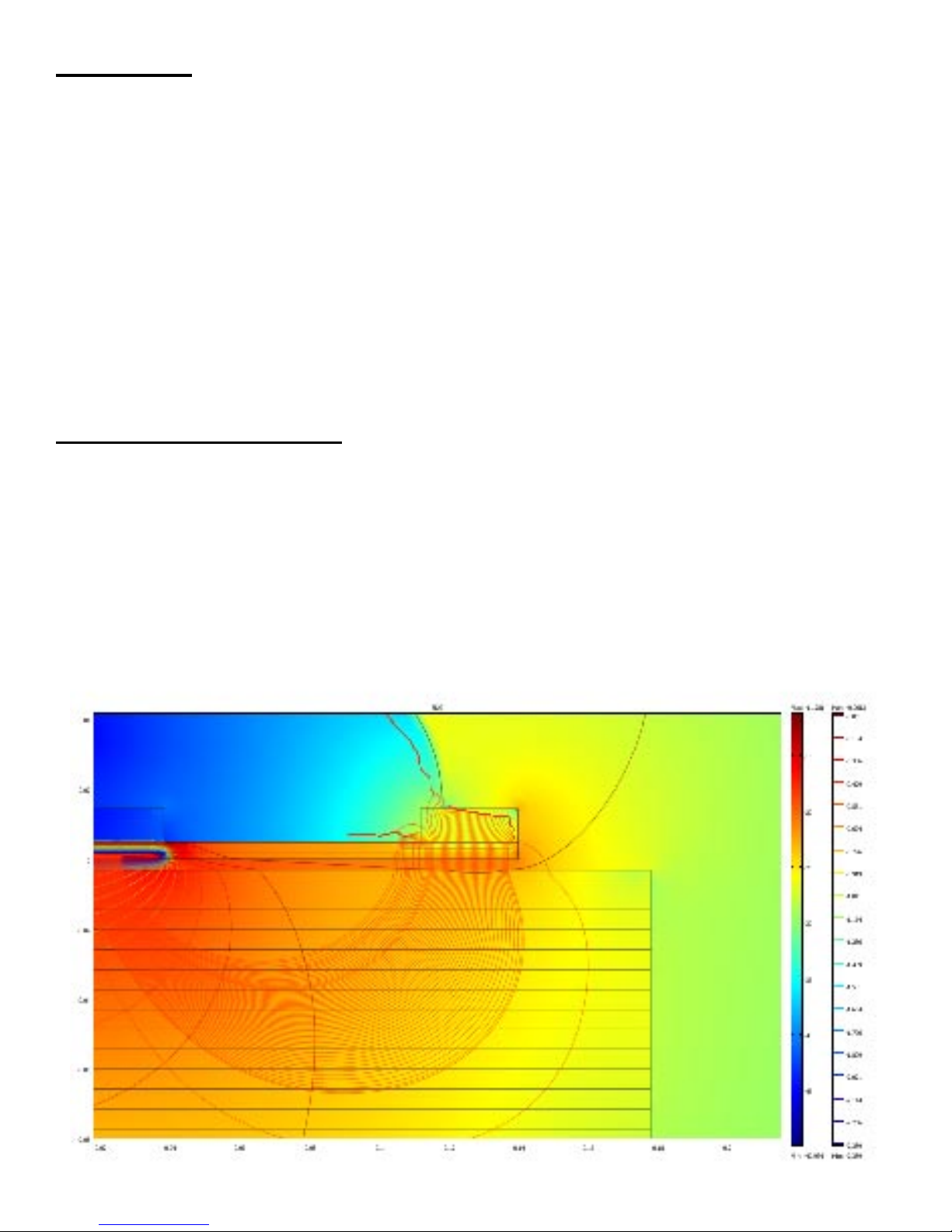
Measurement Technology
Using electrical impedance spectroscopy (EIS) the SDG 200’s measurement permits separation of the effects of
density and moisture content on the response of the soil to electromagnetic probing. The density, or compaction
level, is measured by the response of the SDG 200’s electrical sensing field to changes in electrical impedance
of the material matrix. Since the dielectric constant of air is much lower than that of the other soil constituents,
as density/compaction increases, the combined dielectric constant increases because the percentage of air in the
soil matrix decreases. The SDG 200 performs a calculation on the measurement data that enables the device to
report the soil’s density and moisture content.
3
Page 4

Application Summary
The SDG 200 is intended primarily for making density measurements on a standard 12 inch lift of soil during
or after compaction. It is designed to measure coarse and fine grained materials common in standard soils used
in civil construction projects. After configuring the gauge with soil properties from a standard particle size
distribution report (ASTM D422) and Proctor test (ASTM D698 and D1557) the gauge will provide reliable and
consistent measurements.
Safety
Every effort has been made to make the Soil Density Gauge SDG 200 convenient to use and inherently safe.
The SDG 200 uses non-nuclear, low-voltage direct current to obtain measurements, therefore, there are no
badges, licensing, storage or transport concerns. Like any instrument, however, the user should exercise care
and common sense in its use to prevent mishaps.
Warning
Do not use the unit on or near electrical wiring.
A potential shock hazard exists if contact is made with the exposed wiring.
Warning
Use care in handling the unit. Personal injury can occur through improper handling.
Take proper care to avoid accidentally dropping the unit.
Warning
Unauthorized disassembly of the unit will void the warranty.
Warning
Shipping the gauge with the batteries inside is not recommended.
Caution
Charging the gauge overnight or unattended is not recommended
Caution
Turn the unit off when not in use and during transport.
Caution
Be sure not to switch standardization plates with other gauges. Check the
Serial Numbers located on the gauge and on the plate to be sure they match.
Operating Requirements
Temperature: -4° to 104° F (-20° to 40° C)
Relative Humidity: 10% to 90% noncondensing
Maximum operating altitude: 10,000 feet (3,050 m)
Disclaimer: TransTech reserves the right to change or modify product design, construction, specifications, or
materials without prior notice and without incurring any obligation to make such changes and modifications on
TransTech products previously or subsequently sold.
4
Page 5
Controls and Components
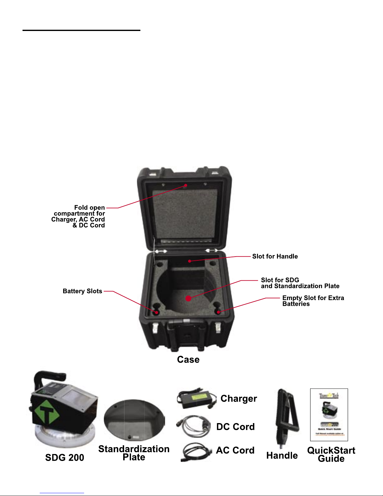
Contents
The SDG200 is packaged and shipped with the following components. Contact TransTech Systems Inc.
Customer Service if any of the parts are missing.
• SDG200 unit
• Storage/shipping case
• Operators Quickstart Guide
• SDG handle
• 120/220V AC to 12V DC battery charger
• 12V DC Car Charger
• 3 battery packs
5
Page 6
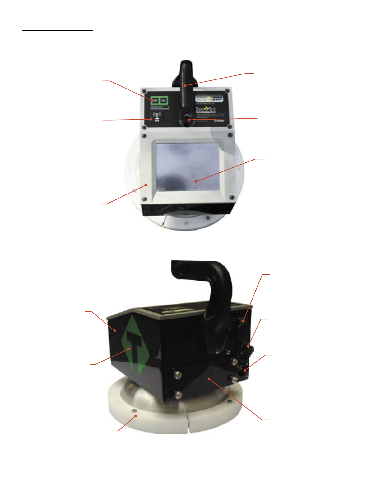
Gauge Features
USB Port
Used to allow
communication between a
flash drive and the gauge
Charger Port
used to connect the ac
or dc charger to gauge
Infrared
Temperature
Sensor
Used to measure the
surface temperature of
the asphalt
Shroud with
10” Sensor Plate
Location where sensor
plate is located
Battery Door
where the battery
is located
Gauge Shell
Body of the gauge
Handle
Used to carry the gauge
TouchScreen
Used to input and
interact with the
gauge
Faceplate
Protective bezel
for touchscreen
GPS Module
Location of GPS
unit on the gauge
(Accurate to
5+- Meters)
On\Off Button
Turns gauge
on and off
Handle Extension
Used to connect handle
extension
Reflective
Vinyl
safety feature for
operation in dark
areas
6
Page 7
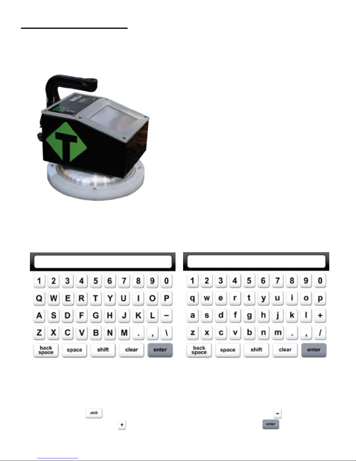
External/Internal Controls
External controls on the SDG 200 consist of an ON/
OFF switch and 480x640 VGA touch screen display
for navigating through the user interface and entering
alpha/numeric data.
Be sure not to drag your finger from one button to
the next. A firm yet light touch is all that is needed to
navigate from screen to screen.
Unique yet consistent icons are located on most screens for easy one touch navigation. When data input is
required of the operator the screen will display the above keyboard. Toggle from upper to lower case letters
using the Shift button The upper case keyboard gives the option of a minus sign while the lower
case keyboard gives the plus sign Once editing is completed simply Press Enter to store and return
to the previous screen.
7
Page 8

The numeric keypad as shown in this example allows for only numbers and a decimal point.
Press Accept to store your entry and in most cases return to the previous screen.
The Status Bar is located at the bottom of the screen (excluding the keyboard screens) and will continuously
update the remaining voltage of the batteries while displaying the date, time and status of the GPS and Data
Logging features.
Prior to using the SDG 200 for the first time the gauge will need to be configured to make measurements and
record data correctly.
The following steps must be completed before operating the SDG 200:
1. Installing and Charging the Batteries
2. Starting the Software
3. Set the Local Time/Set Date
4. Set up the GPS
5. Select Units of Measurement
6. Define the material being tested (Material Details)
8. Define Project Details
Setting up the SDG 200
External/Internal Controls
8
The SDG Model 200 has a built in power saving mode. If there are no buttons pressed after approximately 20
minutes the unit will go into a power saving mode. Pressing any key will “Wake” the SDG up for continued
use. If the SDG is left “On” for an hour without any buttons being pressed, it will shut itself down, to conserve
battery run time
Power Save/Auto Shut Down
Page 9
Installing/Charging the Batteries
To charge the unit, proceed as follows:
1) Turn the SDG 200 unit OFF.
2) Connect the charger to the charger connector located on the back of the SDG 200.
3) Plug the charger into a standard AC outlet.
4) The red indicator lamp will turn green to indicate that the batteries are charged.
5) Unplug the charger from the power source before disconnecting the charger from the SDG 200.
9
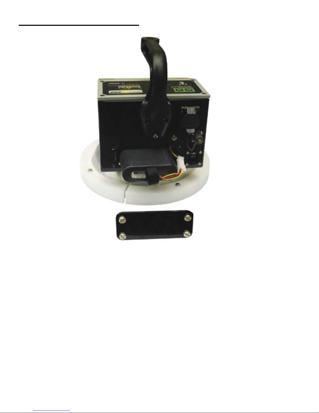
You will find a plate on the back of the SDG 200 with 4 spring loaded bolts.
• Turn each bolt approx. 2 full turns until the spring releases
• Remove the plate from the gauge
• Next you will find a wire with a connector, disconnect the battery from the gauge
• Then pull the nylon strap to slide the battery out of the compartment.
(Do Not pull the battery by the connector wire, doing so could cause damage to the battery)
Plug the gauge in and allow the LED to go from red to green for a full charge.
Approximate charge time is 4 hours.
Page 10
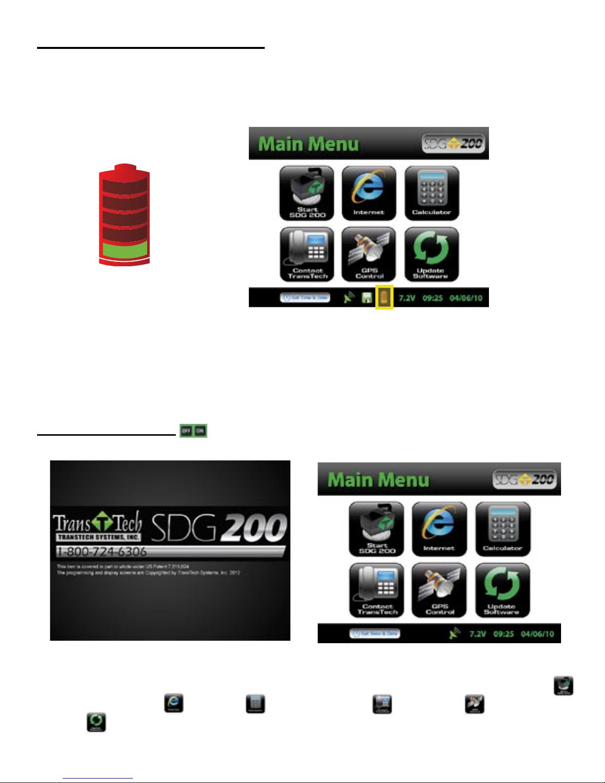
Battery voltage can be viewed on the Status Bar located at the bottom of all screens. A fully charged battery
will display over 8 volts. The battery voltage will decrease as the SDG 200 is used. A low battery icon will be
displayed at approximately 6.5 volts.
The gauge will continue to operate until the battery can not supply enough voltage to complete a measurement.
Once this happens, the gauge will automatically shut down and will not restart until charged. Depending on the
condition of the batteries, once the voltage drops below 6 volts, the gauge may be able to take about 12 to 15
additional readings. It is important to re-charge the battery after each use.
Starting the Software
Turn the SDG 200 on by pressing the ON button. After a few seconds the TransTech splash screen will
appear followed by the Main Menu Screen. The Main Menu screen will display six options. Start SDG200,
Internet (Coming Soon), Calculator, Contact TransTech, GPS Control and Update
Software.
Installing/Charging the Batteries
10
Page 11

Main Menu
Start button when pressed will
open the Control Menu Screen.
The Internet button when pressed will
open a new screen. The new screen
indicates that this will be an option in
the future. It is not active at this time.
The Calculator button when
pressed will open a screen
which functions as a calculator.
The GPS Control button when
pressed will open a screen
which will allow you to enable
or disable the GPS.
Local Time and Change Date Format
The Contact button when pressed
displays TransTech and distributor
contact information.
The Update Software button will
be used in the event that TransTech
releases an update to the software
You may set the date and time in two locations. From the Main Menu, Press Set Time & Date
located on the status bar or from the Control Menu press Date & Time.
11
Page 12
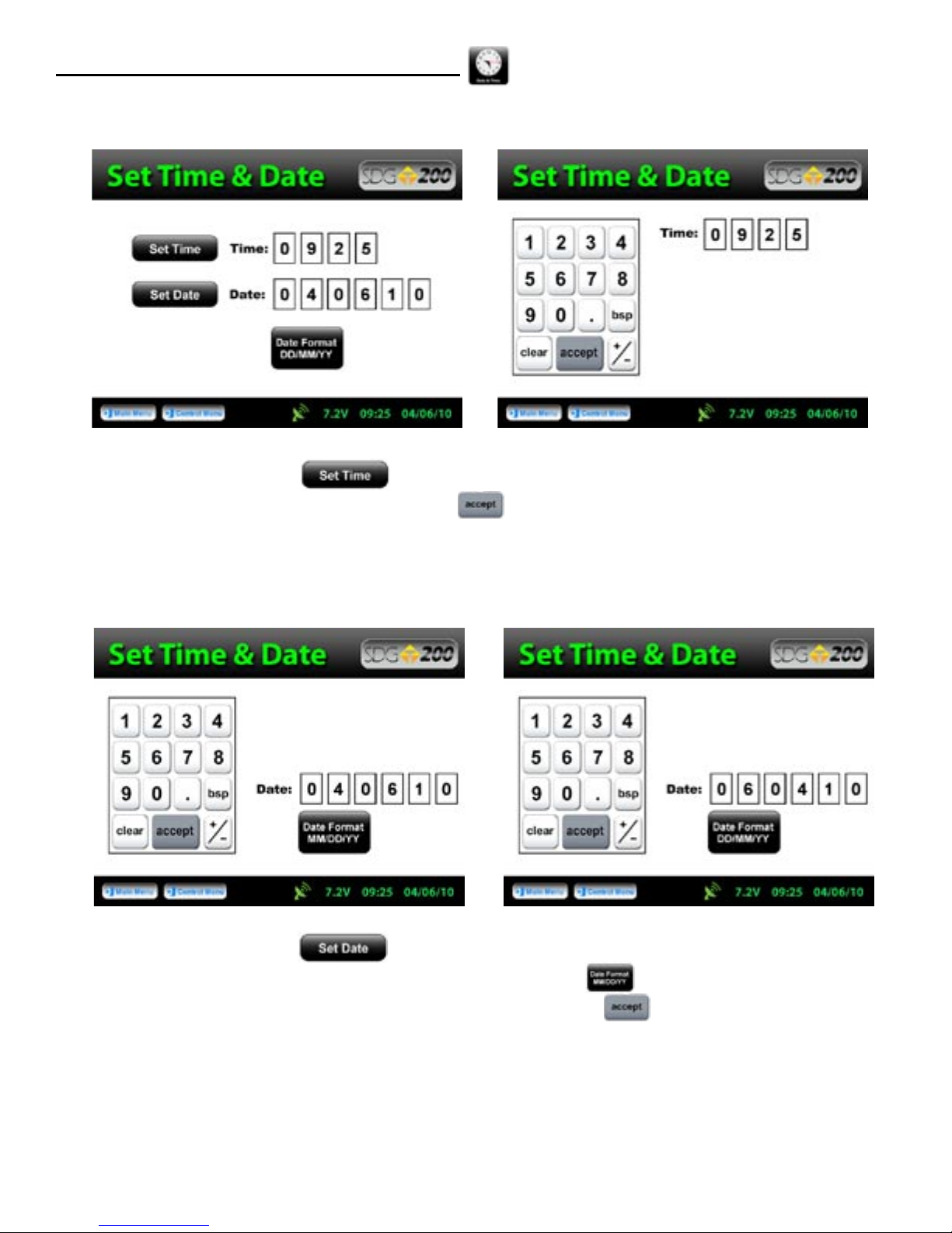
Local Time and Change Date Format
To set the time, Press Set Time. Press the appropriate numbers for the time in 24 hour format.
Once you are satisfied with your entry, Press Accept to store and return to the previous screen.
To set the date, Press Set Date. The date will display in either the DD/MM/YY or MM/DD/YY
format which may be toggled from the button located on both screens. As you did with the time, press
the appropriate numbers for the date in the format chosen. Press Accept to store and return to the
previous screen. (Note: Date will be preset by the factory)
12
Page 13
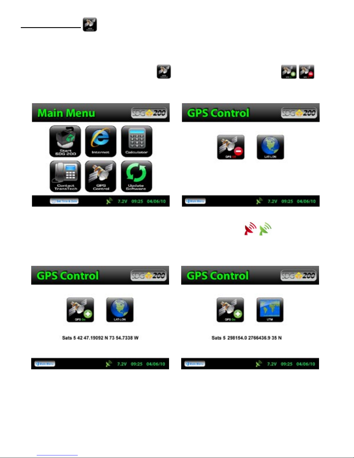
Setup the GPS
Setting up the GPS is nothing more than turning it on and waiting to connect to satellites. It can
take up to 15 minutes to connect to satellites depending on your location.
From the Main Menu, Press GPS CONTROL. GPS status can be toggled ON or OFF.
When the GPS is ON the satellite dish on the status bar turns from red to green.
GPS formatting can also be toggled from the Universal Transverse Mercator (UTM) grid to Latitude/
Longitude (LAT-LON). Initially the display will read Sats 0 for both formats until connections have been
made. The above examples show a connection to five satellites (Sats 5) in both formats. GPS locations will
appear on the bottom left corner of all Reading Mode screens and will store with each reading when Data
Logging is ON.
13
Page 14
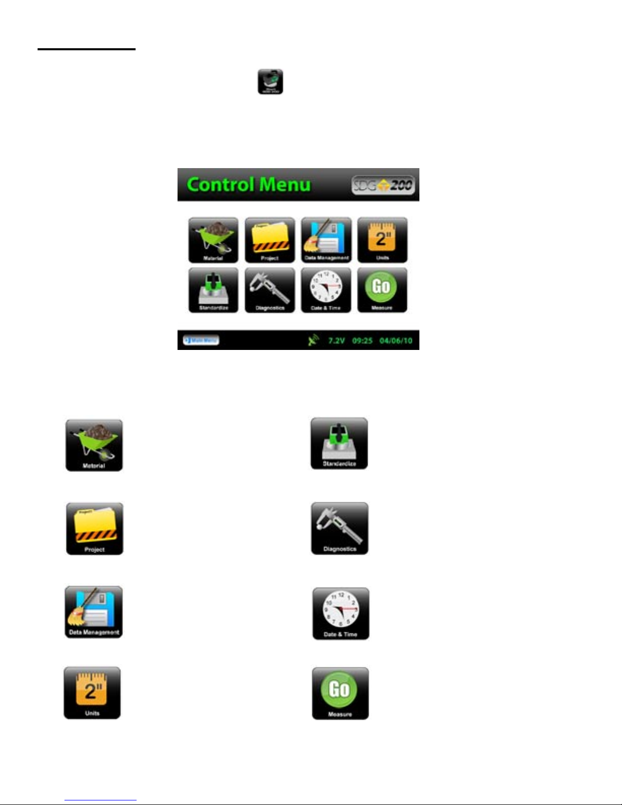
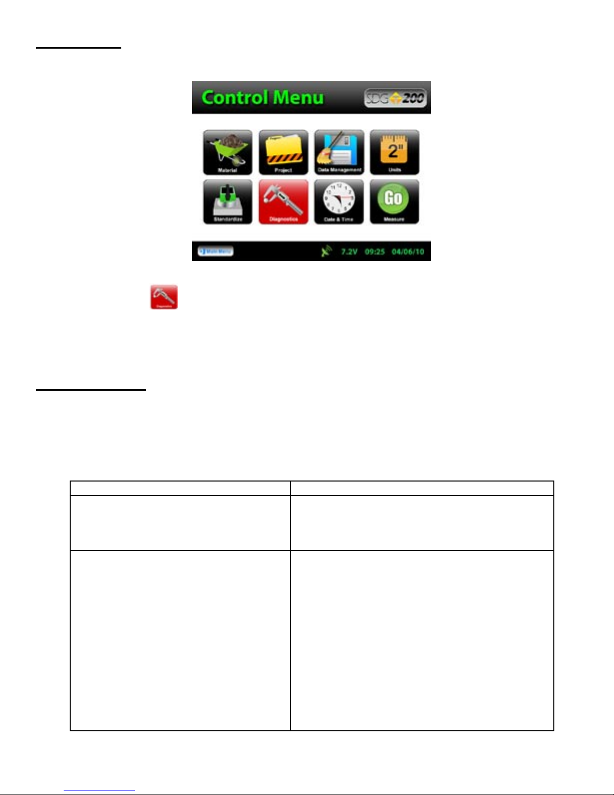
Control Menu
From the Main Menu Press Start SDG 200 to obtain the Control Menu. From this menu, you will find
the icons listed below.
Opens the material details screen
Opens the project details screen
Opens the data management
screen. Here you can delete, download and print job files
Opens the units screen. Here you
can toggle, kg/m3-lbs/ft3, F°-C°,
in-mm
Starts the standardization process
Opens the diagnostics screen
Opens the date and time screen
Starts the measurement process
14
Page 15
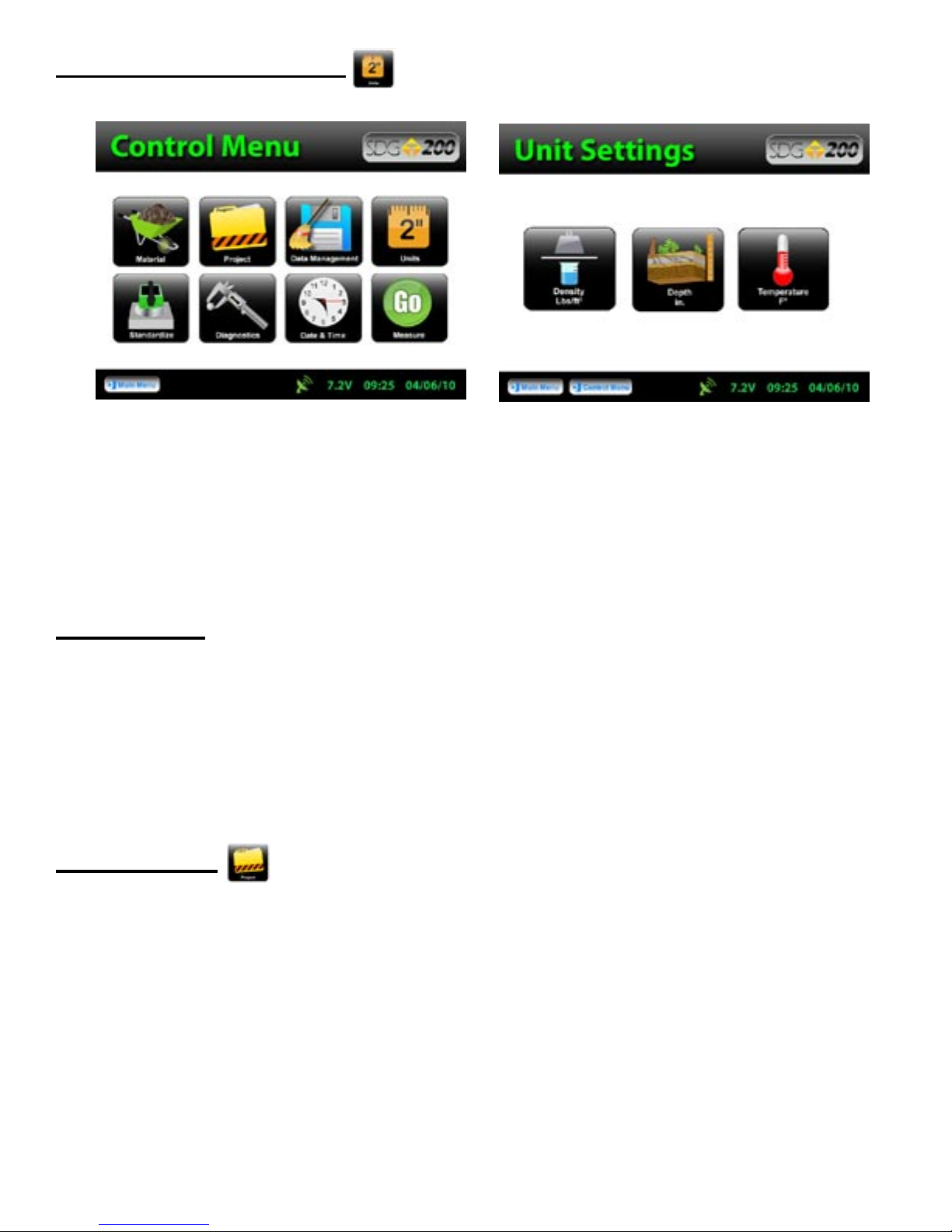
Select Measurement Units
From the Control Menu, Press Units. Density, Temperature and Depth can be toggled independently between
System International (SI “metric”) and U.S. Customary Units. For example, you can set your Density in lb/ft3
while the Temperature is set for Celsius and Depth set to Inches. Press Control Menu on the taskbar to return to
the Control Menu.
Data Logging
The SDG 200 saves data automatically under the Project name that is current while readings are being taken.
Data stored includes all Project and Mix details as well as Dry Density, Wet Density, Percent Moisture,
Volumetric Moisture, Percent Compaction, Soil Temperature, Date, Time, GPS Position, GPS Time and GPS
Date.
Project Details
The SDG 200 is configured to store 10 unique projects that are identified by user entered descriptions. If 10
projects have been defined in the SDG 200 and an 11th project is required, one of the original 10 will need to
be modified to reflect the new project. The details of the new project will need to be input by editing the details
of a previously stored project. Once the old projects are overwritten with new information, the old information
is gone and the new information is saved in the gauge. Previously store data files with the old material
information, however, will not be overwritten.
You may revisit each Project at any given time to continue taking readings. Data from readings taken within
each project will store in the order of which they were taken. If material details change within a project or
project details are added, data for readings taken after the changes will continue to store in the same data file
in the order of which they were taken. Only by changing the Project Name itself will the data be stored in a
separate data file.
15
Page 16
Project Details
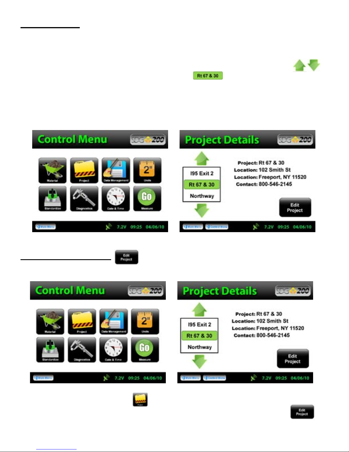
The default Projects stored in a new SDG 200 will have generic Project names (i.e. Project1, Project2, etc)
along with generic Project details (i.e. My Street, My Road, Contact). Project Detail screens will resemble the
Material Detail screen such that you are able to select your Project using the up and down arrows.
The green highlighted project is the CURRENT PROJECT. Readings taken will store in a data
file using the CURRENT PROJECT NAME. If the gauge is shutdown, the current project prior to shutdown
will remain the current project when started back up.
Keep track of your projects by entering detailed information into Project Details.
Editing Project Details
From the Control Menu, Press Project for the Project Details screen. The project highlighted in green
on the left is displayed in detail on the right. To edit the details of this project, Press Edit Project.
16
Page 17
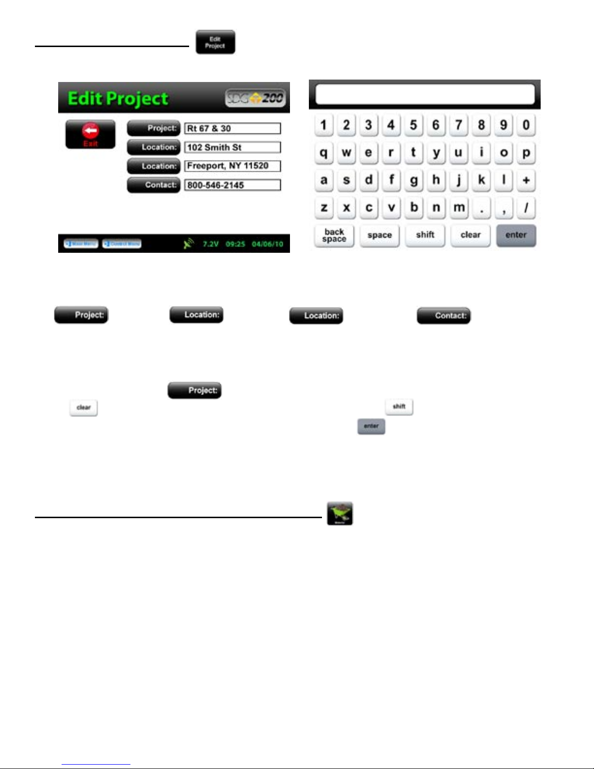
Editing Project Details
There are four black buttons labeled
Project Location Location Contact.
By pressing one of these labeled buttons, you will enter the screen that allows you to store information
for that Project.
For example Press Project, a keyboard allowing you to change the default name will appear. Press
Clear if you would like to start over with a new name. Press Shift to toggle from lower
to upper case letters. Once editing has been completed, Press Enter.
Define, Edit or Upload Material Properties
The density determined by the SDG 200 is highly material dependent so it is extremely important that the
material properties from the Proctor Test and Gradation Report for the soil being tested are input accurately into
the gauge.
The SDG 200 is configured to store 20 unique materials that are identified by user entered descriptions. If 20
materials have been defined in the SDG 200 and a 21st material is required, one of the original 20 will need to
be modified to reflect the material properties of the new material. The properties of the new material will need
to be input by editing the properties of a previously defined material. Once the old material properties are
overwritten with new information, the old information is overwritten and the new information is saved in the
gauge.
The SDG 200 will have default defined materials stored in each of the 20 unique locations. The following
sequence explains how to input new material properties through the keypad or by USB upload and how to edit
previously input material definitions.
17
Page 18

Define, Edit or Upload Material Properties
Note: Be sure that the units of the gauge are set for the same units as the material you are uploading.
If, for example, the gauge was set in U.S. Customary units (ex: 150 lb/ft3) and you were to upload the
material in SI units (2402.8 kg/m3) the gauge will notify you that the density is out of range. However, it
will continue to load the material. If you were to switch to SI units AFTER the material has been loaded,
the density would convert the 2402.8 as if it were in lb/ft3 and result in 38,489.2 kg/m3. Correct this
by deleting the material, change the units of the gauge and reload the material or by simply editing the
density in the material setup.
See Part 5 for explanations of the Material Properties.
See Part 6 for explanations of gradation and Proctor test reports.
See Appendix A for explanations of the MTL Generator
Defining and Editing a Material
Here you may use the green up or down errors to select a new material for editing or change an existing
material. The green highlighted material is the CURRENT MATERIAL that the gauge will use when
taking readings. Prior to exiting this screen, be sure this is the material you want and the information to
the right has been verified. Press Control Menu on the Status Bar (bottom middle) to return to the Control
Menu. If the gauge is shutdown, the current material prior to shutdown will remain the current material when
started back up.
!! Note: The sum of %Greater the 3 inches, %Gravel, %Sand, and %Fines must add up to 100%. The
default values programmed in the SDG software add up to 100%. As soon as one of those values is
edited, the sum will no longer add up to 100% and an error message will be displayed, however, after the
initial error the gauge will allow you to exit and begin taking readings. THIS IS NOT RECOMMENDED
AND WILL GIVE INACCURATE RESULTS!!
!! Note that Max Dry Density and Dry Density Offset must be entered in the same units in which the
gauge is configured to output results. Example: If the gauge is configured to measure in pcf, input Max
Dry Density in pcf !!
18
Page 19
Defining and Editing a Material
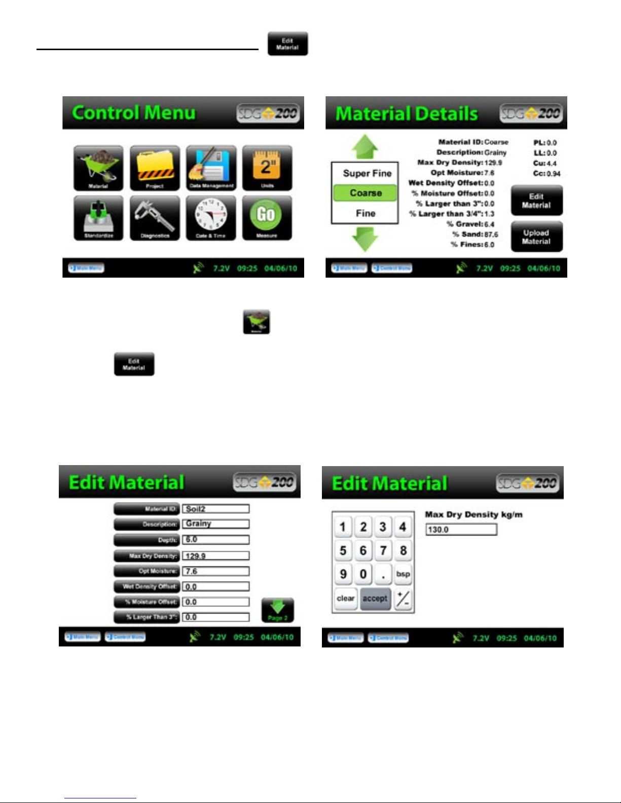
From the Control Menu, Press Material for the Material Details screen. The material highlighted in
green on the left is displayed in detail on the right. To edit the details of this material, Press
Edit Material.
There are fifteen material properties for each material. Eight of these material properties are listed on Page one
of the Edit Material Page and the remaining seven are listed on Page 2. Each can be edited individually by
pressing its corresponding label which prompts a numeric or alpha numeric keypad.
19
Page 20
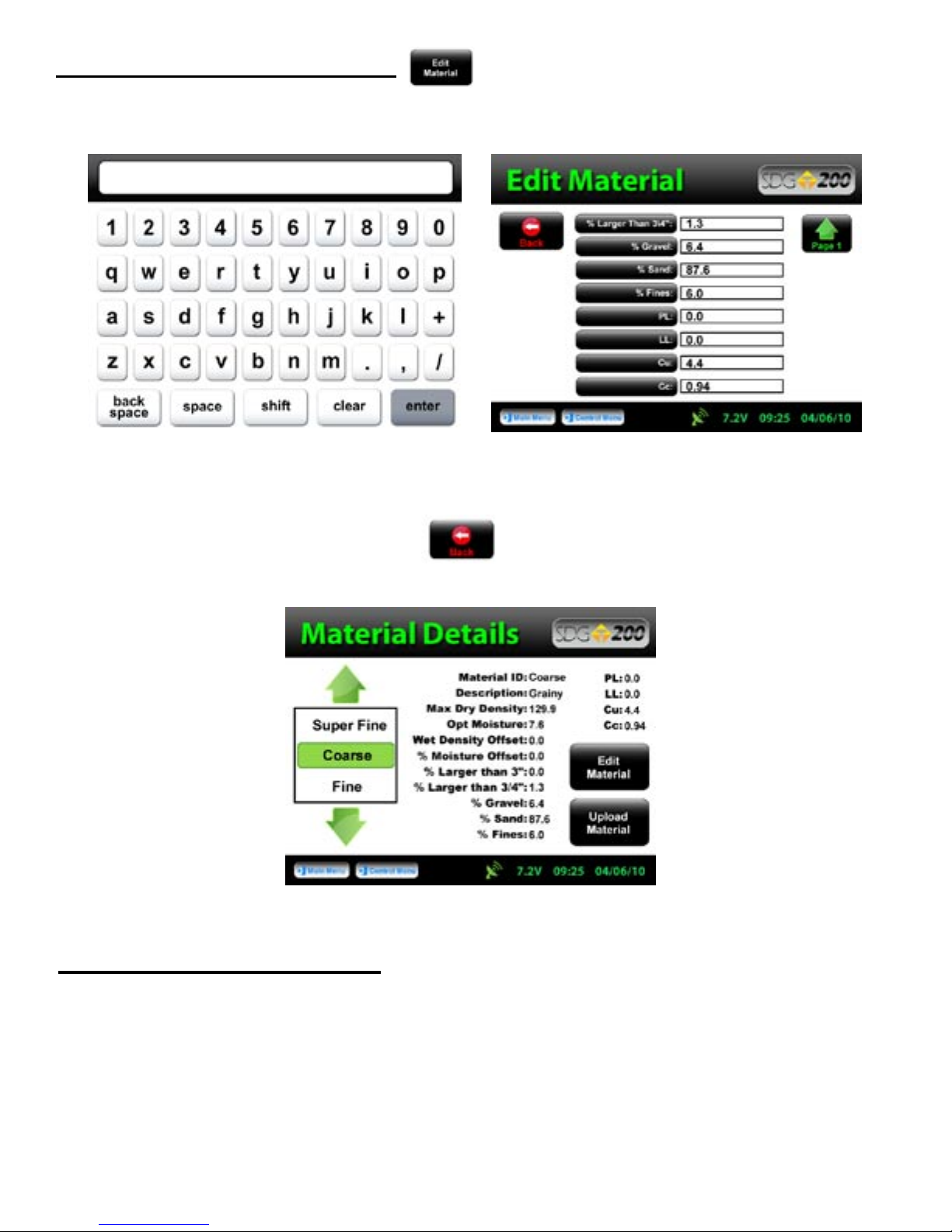
Defining and Editing a Material
Once editing is complete, Press the Back button located on Page 2 to verify your changes on the
Material Details page.
Setting Measurement Offsets
The SDG 200 has been designed to determine the moisture and density in a compacted soil sample without
the need for any offsets. The ability to measure moisture and density is based on an empirical model that
was developed by studying common soil types at near optimum moisture contents with typical particle size
distributions. As the SDG 200’s measurement performance is based on this empirical model, there will be
occasions where the soil being measured is so different from one that has been studied previously that an offset
may be required to enable the SDG 200 to produce acceptable results.
20
Page 21

Setting Measurement Offsets
Offsets for Wet Density and % Moisture can be set manually by the operator in cases where the SDG 200
does not appear to be comparing favorably to collocated measurements. The offsets are simply added to
or subtracted from the Wet Density and % Moisture calculated by the SDG 200. Dry Density, Volumetric
Moisture, and % Compaction are then recalculated based on the offset values of Wet Density and % Moisture.
The Wet Density and % Moisture offsets are saved in each data record
with the results of the corresponding test in the .mnt file.
Wet Density and % Moisture offsets are entered into the SDG 200 as a material property and are displayed and
edited identically to other material properties.
Wet Density and % Moisture Offsets can be either negative or positive. To enter a positive offset simply type
in the offset value that will be added to the current measurement. To enter a negative offset, use the (-/+) key to
enter a negative sign then enter the value that will be subtracted from the measured value. After the offsets are
applied to the Wet Density and % Moisture, Dry Density and Volumetric Moisture are calculated by the SDG
200 as follows:
The % Moisture Offset is input as a percentage. For example, if the SDG 200 is consistently measuring %
moisture as 7.5% and a collocated reference measurement is consistently measuring 5%, inputting an offset of
-2.5 will adjust the SDG 200 to yield results similar to your reference measurement.
The Wet Density offset is input in units of mass/unit volume. If the gauge is set to operate in kg/m³, the offset
will need to be entered in kg/m³. If the SDG 200 is configured to operate in lb/ft³, the density offset will need
to be entered in lb/ft³.
The moisture, density, and compaction values displayed by the SDG 200
and logged in the .mnt file reflect the application of the user selected offsets
Failing to enter the Wet Density Offset in the same units that the
SDG 200 is Configured to measure in may result in significant errors.
21
Page 22
Determining Offset Values
Methods used to determine what offsets are appropriate will vary from application to application, but will all
generally follow the same steps. In order to determine an offset, a reference measurement will be required.
That reference may include one or more of the following: a Nuclear Density Gauge, Oven Dry Moisture
Measurements, Speedy Moisture Measurements, Sand Cone Apparatus, Balloon Density Apparatus, Density
Drive Cone or other applicable equipment.
Multiple measurements should be taken at three to five representative locations with both the SDG 200 (make
sure both offsets are set to 0) and your appropriate reference equipment. Note the results by each method at
each location and determine the average difference between the SDG 200 results and the reference measurement
results. This average difference will be your offset. If the SDG 200 measures lower than your reference
measurement your SDG 200 offset will be positive. If the SDG 200 measures higher than the reference gauge,
your SDG 200 offset will be negative.
At a particular location, if you are not able to get repeatable measurements with either the SDG 200 or your
reference equipment, there may be an anomaly in the soil that effects the equipment and a new location should
be selected.
!!Arbitrary selection of offsets is not recommended!!
Uploading a Material
A material definition that has been set up using the SDG 200 Gradation Calculator and saved on a USB flash
drive can be uploaded to the SDG 200.
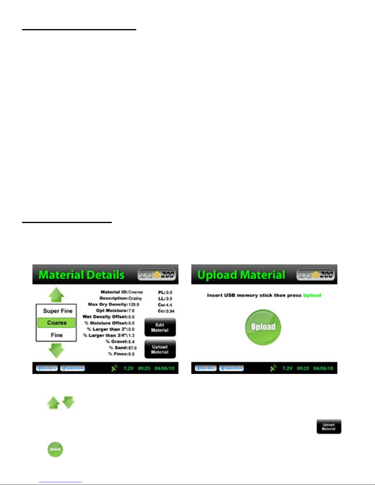
From the Material Details screen choose the material name you wish to overwrite by pressing the up or down
arrows. The green highlighted material name displayed prior to uploading the material will be the
location the new material will be stored. The information that is stored in this location will be overwritten and
you will not be able to retrieve it again. Once you have made your choice, Press Upload Material.
Be sure to have your USB drive inserted into the USB port located on the back of the gauge. Press
Upload.
22
Page 23
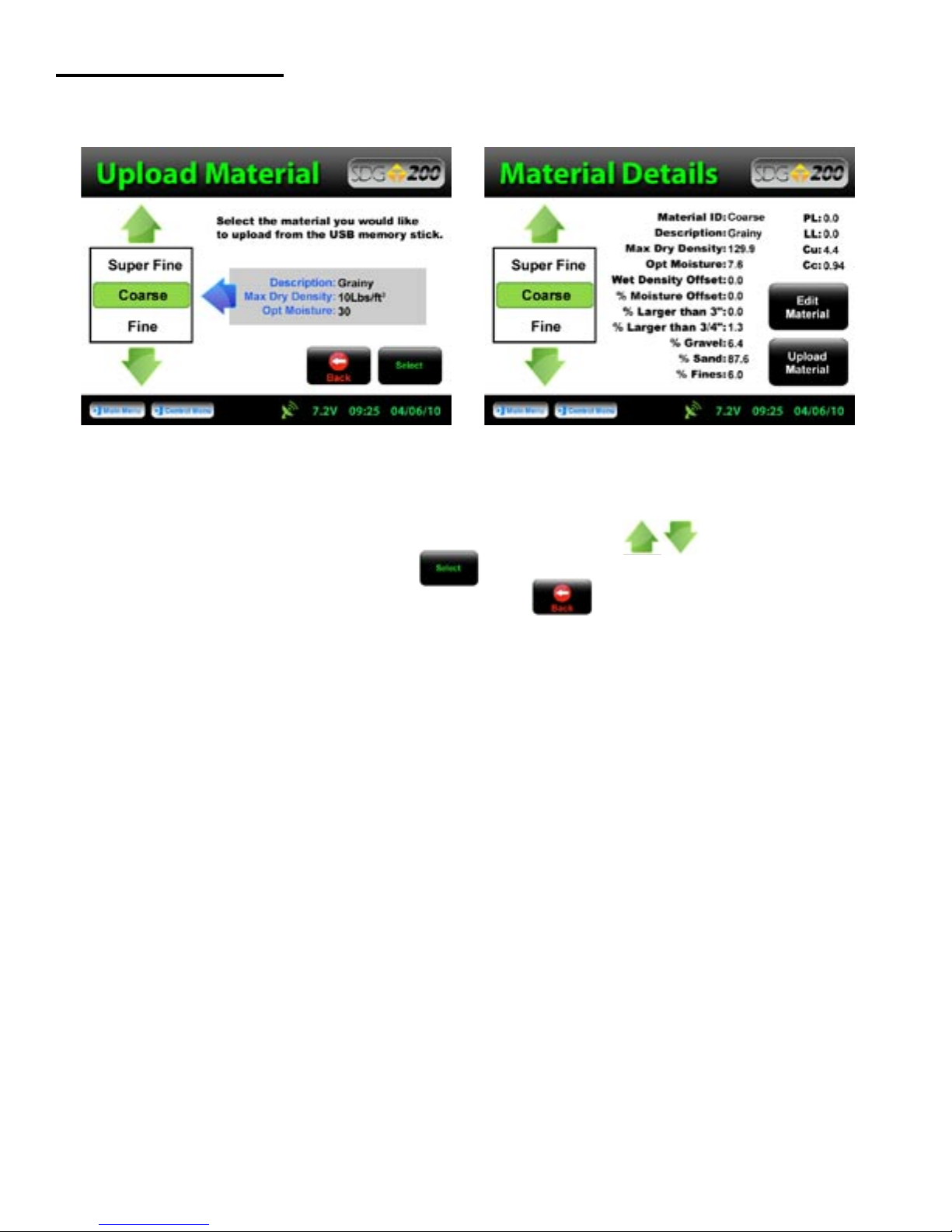
Uploading a Material
The file name of the materials located on the USB drive will appear on the left and some details identifying that
specific material will be displayed on the right. Use the up or down arrows to highlight the material
you wish to upload. Once verified, Press Select to upload the material information into the gauge.
Continue to select additional materials to upload or Press Back to view the material in detail.
Note: Be sure that the units of the gauge are set for the same units as the
material you are uploading. If, for example, the gauge was set in U.S.
Customary units (ex: 150 lb/ft3) and you were to upload the material in
SI units (2402.8 kg/m3) the gauge will notify you that the density is out
of range. However, it will continue to load the material. If you were
to switch to SI units AFTER the material has been loaded, the density
would convert the 2402.8 as if it were in lb/ft3 and result in 38,489.2 kg/m3.
Correct this by deleting the material, change the units of the gauge and
reload the material or by simply editing the density in the material setup.
See Appendix A for explanations of the SDG MTL Generator
23
Page 24

Part 2: Running a Test
Measurement Pattern
A complete test consists of five individual measurements taken in a “cloverleaf” pattern at the test location.
Each of the five measurements takes about 10 seconds. The SDG 200 is placed in position 1 for the first
measurement and moved clockwise around position 1 as indicated in the illustration above. Upon completion
of each reading, the SDG 200 will prompt the operator to move to the next location.
Surface Preparation
While the SDG 200 unit stands off from the soil, surface condition is still important. It is necessary for the soil
surface to be free from any loose and disturbed material, stones, large air pockets or ‘divots’ and other debris.
It is also important that the soil surface be smooth. If it is not, smooth out the surface or move the unit to a
location where the surface is smoother. The SDG 200 should not rock side-to-side when placed in a location to
take a measurement; if it does, move to a new location or remove the obstacle that is causing the rocking being
careful to not measure on top of any ‘divot’ left by removal of the object.
Large metal objects should not be within three feet of the gauge or underneath the soil while taking
measurements. Measurements within ten feet of buried power lines should be avoided. When possible,
measurements taken with an SDG 200 near an edge or vertical obstruction should be taken at least three inches
from that edge.
When placing the SDG 200 at a location for a measurement, do not push down on the unit to ‘seat’ the
unit in place. Set the unit down on the surface and check to see if it rocks side-to-side.
Do not touch the SDG while it is taking a measurement.
24
Page 25

Measure Density
Turn the SDG 200 on by pressing the ON button. After a few seconds the TransTech splash screen
will appear followed by the Main Menu screen.
The Main Menu screen will display six options.
Start SDG200 Internet (Coming Soon) Calculator Contact TransTech GPS
Control and Update Software.
From the Main Menu, Press Start SDG 200 to get to the Control Menu. Press Material to
display and verify the details of the current material that will be used for this test. Once verified, Press Control
Menu from the status bar.
25
Page 26

Measure Density
Press Project to verify the Project Name that the data will store under as well as the Project Details.
Once verified, Press Control Menu from the status bar.
Press Measure, to enter into the Soil Reading screen. In the bottom left corner, the name of the material
to be tested and project are displayed for verification as well as the temperature of the soil. In the bottom right
corner, the GPS information is displayed. The cloverleaf pattern is also displayed for your convenience with the
highlighted position being the current position to measure.
26
Page 27

Measure Density
Position the gauge on the material in position 1 as it appears on the screen. Do not touch the gauge while it is
busy taking a measurement. When reading 1 is complete, the green 2 will be illuminated. Move the
gauge to position two and press 2. Repeat this for the five measurements. After the fifth measurement has been
taken, the in place density and moisture content will be calculated and displayed on the screen. Here you can
choose to “Accept” or “Reject” the recording of the averages into the data file.
After pressing “Accept”, the Enter Location screen will appear allowing for a Description of the
location to be entered as well as the Operator name. This information will be stored in the data file and will
remain for future readings until edited. Once editing is complete, Press Back to return to position one
of the Soil Reading screen to continue taking measurements. If you chose to press “Reject”
instead of “Accept”, the reading will not be stored and the gauge will return to position one of the Soil
Reading screen.
27
Page 28

Select a Different Material to Test
At any time you wish to go back and change the Material to be tested you may do so.
From the Control Menu, Press Material. By using the up or down arrows you can change
the material, return to the Soil Reading screen and begin testing. However, keep note that these readings will
be stored under the same Project Name that you were just using (the current Project). The data file name will
be the same as the Project Name and will consist of the details on any and all materials used while that Project
Name is current or active. Only by changing the current Project Name will you receive a separate data file.
28
Page 29

Part 3: Data Storage and Downloading Data
The SDG 200 saves two types of data files. One file contains information that is referred to as diagnostic data,
the other file contains information that is referred to as measurement data. Data files can be removed from the
SDG 200 via a USB flash drive.
Measurement Data
The measurement data is a record of all of the tests performed with the instrument (a test is made up of the 5
individual measurements taken in a cloverleaf pattern). It is a semi colon delimited text file containing the
following information:
Internal: Software Version; Gauge SN;
Results: Dry Density; Wet Density; Moisture Content (%);
Volumetric Moisture; % Compaction;
Special Features: Soil Temperature; SDG Time; SDG Date; GPS Position;
GPS Time; GPS Date;
Project Details: Project Name; Project Locations; Project Contact;
Description; Operator;
Material Details: Material ID; Description; Max Dry Density;
Optimum Moisture; %Greater than 3in; %Greater than in;
%Gravel; %Sand; %Fines; PL; LL; Cu; Cc; A coefficient;
B coefficient; Dry Density Offset; % Moisture Content Offset
When the measurement file is downloaded it is automatically named by the SDG 200. The following naming
format is used:
Project Name:month:month:day:day:hour:hour:minute:minute.mnt
Project 103061510.mnt for Project 1 of March 6, 3:10 PM
Diagnostic Data
The diagnostic data contains all of the measurement data as well as information that indicates how the SDG 200
is performing. This data is of little interest to gauge owners and operators but will be very helpful to TransTech
in the event of an instrument malfunction. Similar to the measurement data, the diagnostic data is saved at the
conclusion of a complete measurement. Data from partial measurements are not logged in memory.
When the diagnostic file is downloaded it is automatically named by the SDG 200. The following naming
format is used:
Project Name:month:month:day:day:hour:hour:minute:minute.dat
Project 103061510.dat for Project 1 of March 6, 3:10 PM
29
Page 30

Storage Capacity
The SDG 200 has the capability to store up to twenty detailed projects and twenty detailed materials with an
overall storage capacity of over 1000 MB for all data files. Upon completion of a set of five measurements, the
complete details of the test will be written to a file and saved on the instrument ONLY AFTER THE ACCEPT
BUTTON HAS BEEN PRESSED. This feature is new to the SDG 200 where the older 100 series saved
automatically. With the 200 series, the gauge gives the operator the option to accept or decline.
On occasions that operators do not complete the series of five readings that make up a complete measurement
series and either exits out of the reading routine or turns off the instrument, that incomplete record will not be
stored. If the operator tries to exit out of the reading as it is being taken a warning will display: “Attention!
Measurement currently running; please stop measurement.” Simply wait for the measurement to complete.
If the operator decides to decline the completed set of readings, the gauge will not store that set.
Downloading Data
From the Control Menu, Press Data Management. Project files will be stored and downloaded here.
Scroll down to the Project you would like to download using the arrows located at the top left corner
of the screen. Insert the USB flash drive into the USB port located on the back of the gauge. Press “Download
DAT & MNT” if you wish to download the measurement data as well as the diagnostic data.
Press “Download MNT” if you wish to download the measurement data only. You will be
prompted to insert the USB flash drive if you haven’t already and then to press Download. The gauge
will return to the Data Management screen which now displays BUSY
in the top right hand corner. Downloading is complete when the gauge displays READY.
Deleting a Project File
When and if you wish to delete a Project, be sure to highlight the correct project and Press “Delete”.
A warning will display to be sure you wish to delete the file. Once deleted, you will no longer be able to
retrieve the measurement nor the diagnostics data.
30
BUSY
READY
Page 31

Part 4: Maintenance and Troubleshooting
In the event that the SDG 200 were to malfunction internal information about the gauge can be obtained and
relayed to the factory. In the event that a repair is required, it is strongly recommended that authorized factory
service be obtained. Unauthorized repair or maintenance by the user will void the unit’s warranty
From the Control Menu, Press Diagnostics and the internal information needed for the factory to track
your gauge will display. This information consists of the Serial Number, Software Version and the date the
gauge was last calibrated.
Maintenance
The SDG 200 has been designed to require a minimum of maintenance or service. Normal care in use should
insure long and trouble free operation.
Keep SDG bottom surface clean:
For accurate readings, the SDG 200 should have a smooth interface with the surface. Try not to place the SDG
200 on top of large rocks that would cause the gauge not to sit properly. Also, do not try to “dig” the gauge into
the material.
Touchscreen:
Do not clean the touchscreen with abrasive products, solvents or other harsh cleaners. Apply window cleaner to
a clean soft rag and wipe the surface clean.
Factory Calibration:
Yearly recalibration of the gauge is recommended to maintain consistency and accuracy for the electronic
components.
31
Page 32
Maintenance
The Diagnostic button on the Control Menu will turn red as a reminder. Only authorized distributors or
the factory are able to perform this type of calibration.
Troubleshooting
The chart below provides guidance to a few suspect conditions.
Problem
Buttons Sticking/Frozen Software
Incorrect Density Reading
Repress the frozen button firmly for three seconds.
Be sure not to drag your finger from one button to
the next. If this does not work, reset the gauge by
turning it off and then back on.
Clean off sensor plate
Check Current Material Details -be sure you have
entered all details correctly (ex. Does the %Gravel,
%Sand and %Fines add up to 100%?)
Check Offsets-if you entered a Dry Density Offset or
a %Moisture Offset be sure that the values selected
make sense (see the Definitions and Calculations
section of this manual)
Check Units-be sure all of the values for the Density
whether uploaded or entered, are in the same units
Call Factory
Remedy
32
Page 33
Troubleshooting
The chart below provides guidance to a few suspect conditions.
Problem
Battery Problems/Gauge Keeps Shutting
Down/Gauge Will Not Come On
Data is not recording Check Current Project Name-data readings will
GPS Communication Errors
Part 5: Definitions and Calculations
Measurement Results
Remedy
Ensure battery pack is plugged in
Check battery voltage-plug gauge into charger and
wait for the green LED to illuminate to indicate a full
charge
Call Factory
store on the Current Project only, be sure you have
the correct Project name set on the gauge (Verify the
name of the Project and Mix on each reading screen)
Call Factory
The following values are reported at the end of a measurement:
Wet Density is the total mass of material per unit volume in pcf or kg/m³
Volumetric Moisture is the mass of water per unit volume in pcf or kg/m³, measured by the SDG.
% Moisture = water content as percent of dry density =
Dry Density = Wet Density – Volumetric Moisture
% Compaction = Dry Density
Max Dry Density
33
Page 34

Definitions of Material Properties
The following descriptions and material properties need to be entered in the gauge for measurement or data
reporting purposes:
Material ID: Usually a numeric entry that will associate the soil being tested with the gradation and proctor
test report. Examples of soil or material ID’s may include ’33.1099’ or ‘776632. Material IDs are limited to 13
characters.
Description: Typically a brief description of the soil that allows the operator to visually identify the material
being tested. Examples may include ‘clayey sand red’, or ‘light brown silt’. Descriptions are limited to 13
characters.
Max Dry Density: This is the maximum dry density or target density or Proctor number for the material being
tested. It is input in pcf or kg/m³. Be sure the units of the gauge are in the same units you wish to enter.
This value can be found in a Proctor test report completed in accordance with ASTM D 1557 or ASTM D 698.
This is used by the SDG as the value against which the measured dry density is compared to calculate percent
compaction.
Opt Moisture: This is the optimum moisture content for the material being tested. This value can be found in
a compaction test report completed in accordance with ASTM D 1557 or ASTM D 698.
PL: Plastic Limit. This property describes soils with a high clay and silt content. It is defined as the moisture
content in percent at which the sample begins to exhibit plastic behavior as it transitions from having semi-solid
properties. This value is determined as outlined by ASTM D 4318.
LL: Liquid Limit. This property describes soils with a high clay and silt content. It is defined as the moisture
content in percent at which a sample begins to exhibit liquid behavior as it transitions from having plastic
properties. This value is determined as outlined by ASTM D 4318.
Cu: Coefficient of Uniformity. Cu is defined as the ratio of D60 / D10, where D
is the particle diameter of
60
which 60% of the sample is smaller, and D10 is the particle diameter of which 10% of the sample is smaller. Cu
can be calculated from values taken from a particle size distribution plot defined by ASTM D 422.
Cc: Coefficient of Curvature. Cc is defined as D
2
/ (D60 x D10). Cc can be calculated from values taken from a
30
particle size distribution plot defined by ASTM D 422.
% Gravel: The percentage of material by mass passing a 3 in. (75mm) sieve but retained on a #4 (4.75mm)
sieve. %Gravel can be taken from a particle size distribution report defined by ASTM D 422.
% Sand: The percentage of material by mass passing a #4 (4.75mm) sieve but retained on a #200 (75μm).
%Sand can be taken from a particle size distribution report defined by ASTM D 422.
% Fines: The percentage of material by mass passing a #200 (75μm) sieve. %Fines can be taken from a
particle size distribution report defined by ASTM D 422.
Note: Be sure that the % Greater than 3”, % Gravel, % Sand and the % Fines add up to 100%.
% Greater than in: The percentage of material by mass retained on a inch (19.0mm) sieve. % Greater
than inch can be taken from a particle size distribution report defined by ASTM D 422.
% Greater than 3 in: The percentage of material by mass retained on a 3 inch (75 mm) sieve. % Greater than
3 inches can be taken from a particle size distribution report defined by ASTM D 422.
34
Page 35
Part 6: Standardization of the SDG
To assure that the SDG 200’s ability to make consistent measurements has not been compromised, a daily
measurement should be taken on a reference material and tracked day to day for any unacceptable variations. A
metallic plate has been installed in the bottom of the SDG 200 carrying case that is suitable for this purpose.
Although this verification is referred to as a standardization of the gauge, the results of the
standardization in no way influence the measurement of the gauge, they only serve to alert the user to a
change in the way that the gauge is operating. Unexpected changes in the standardization values should
be noted and discussed with Product Service at TransTech.
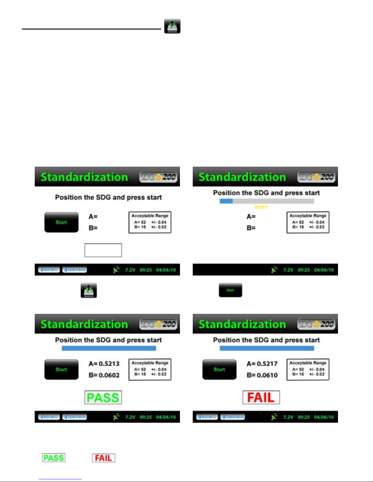
Standardizations are performed inside the carry case. Located at the bottom of the case is a steel plate.
Position the gauge on top of the plate inside the case. Be sure the gauge screen is facing you, if it is placed
in the case backwards the handle will prevent proper seating you will get a false reading. The case should
not be on top of or around (10ft.) any large metal objects. Turn the gauge ON and proceed to the Control
Menu.
Press Standardize, to obtain the above screen. Press Start, and do not touch the gauge while it
is busy.
The acceptable range for the A and B values are displayed on the screen, however, the gauge will respond with a
PASS or Fail based on these ranges automatically.
35
Page 36
Part 6: Standardization of the SDG
If you receive a Fail, prior to calling the factory try the following:
1) Reposition the gauge/case to another location (outside preferably)
2) Be sure that you are testing the gauge inside the carry case that was provided with the SDG.
The gauge and case are paired during production to determain the standardization.
3) Do not place the case on the back or near an automobile as well as any other large metal
objects and/or wires
4) Be sure that no foreign objects have adhered to the bottom of the gauge or on the steel plate
5) Shut off all cell phones within 10ft of the gauge
WARNING: THE STANDARDIZATION OF THE SDG 200 WILL ONLY WORK WITH THE PLATE
IT HAS BEEN ISSUED TO. IF YOU RECEIVE A FAIL RESULT, CHECK TO BE SURE THE SERIAL
NUMBERS LOCATED ON THE GAUGE AND THE STANDARDIZATION PLATE ARE THE SAME.
WARNING: THE STANDARDIZATION OF THE SDG 200 MAY GIVE A FALSE “FAIL” IF TEST IS
TAKEN TOO CLOSE TO METAL OBJECTS, POWER LINES OR OTHER ELECTRICAL DEVICES
THAT MAY BE TOO CLOSE TO THE GAUGE. TURN THE GAUGE OFF AND MOVE THE GAUGE
ATLEAST 10 FEET FROM THESE OBJECTS. IF AFTER THESE PRECAUTIONS ARE TAKEN
THE GAUGE STILL DISPLAYS A “FAIL” CONTACT YOUR DISTRIBUTOR.
Part 7: Explanation of Gradation and Compaction Reports
All of the information needed to configure an SDG 200 to measure the density and moisture content of
a material is available on Compaction Test Reports (Proctor Test) and Particle Size Distribution Reports
(Gradation/Sieve Analysis) completed as outlined by ASTM D 422 and ASTM D 1557. In order to configure
the gauge to operate on materials that have high clay and silt contents, results from an Atterberg limits test
(ASTM D 4318) will be needed as well.
36
Page 37

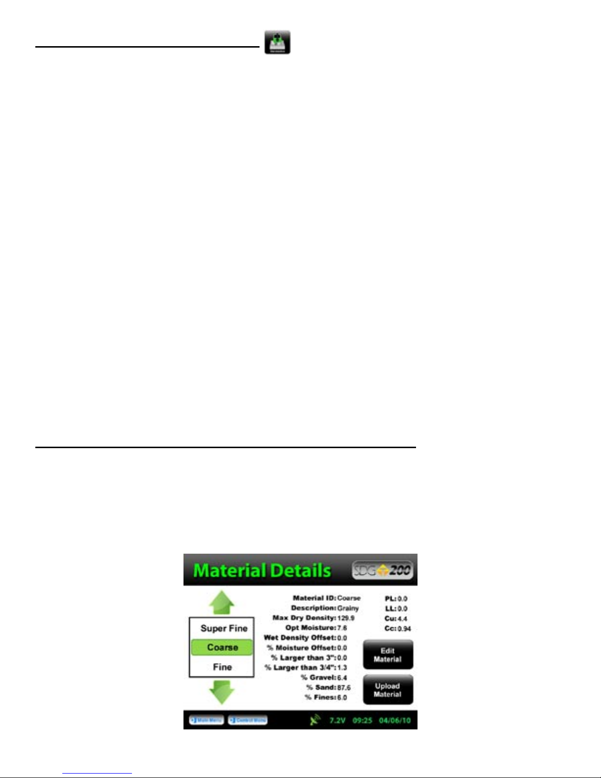
Part 7: Explanation of Gradation and Compaction Reports
The thirteen properties that will need to be entered through the SDG’s user interface are shown on the Material
Details screen above and defined below. Further definitions of these properties can be found in Part 5 of the
SDG Operators Handbook. Examples of a gradation report and compaction test are on the following pages.
The Material ID is any identifier that can associate the material being evaluated with its test report. A report
number or sample number should be entered here. For the example shown, 08.0527 is the Soil ID. Do not
enter letters or characters as part of the Soil ID.
The Description should be a used to describe the material and help make a visual association with the material
being tested. Dark Brown Sand is used for this example.
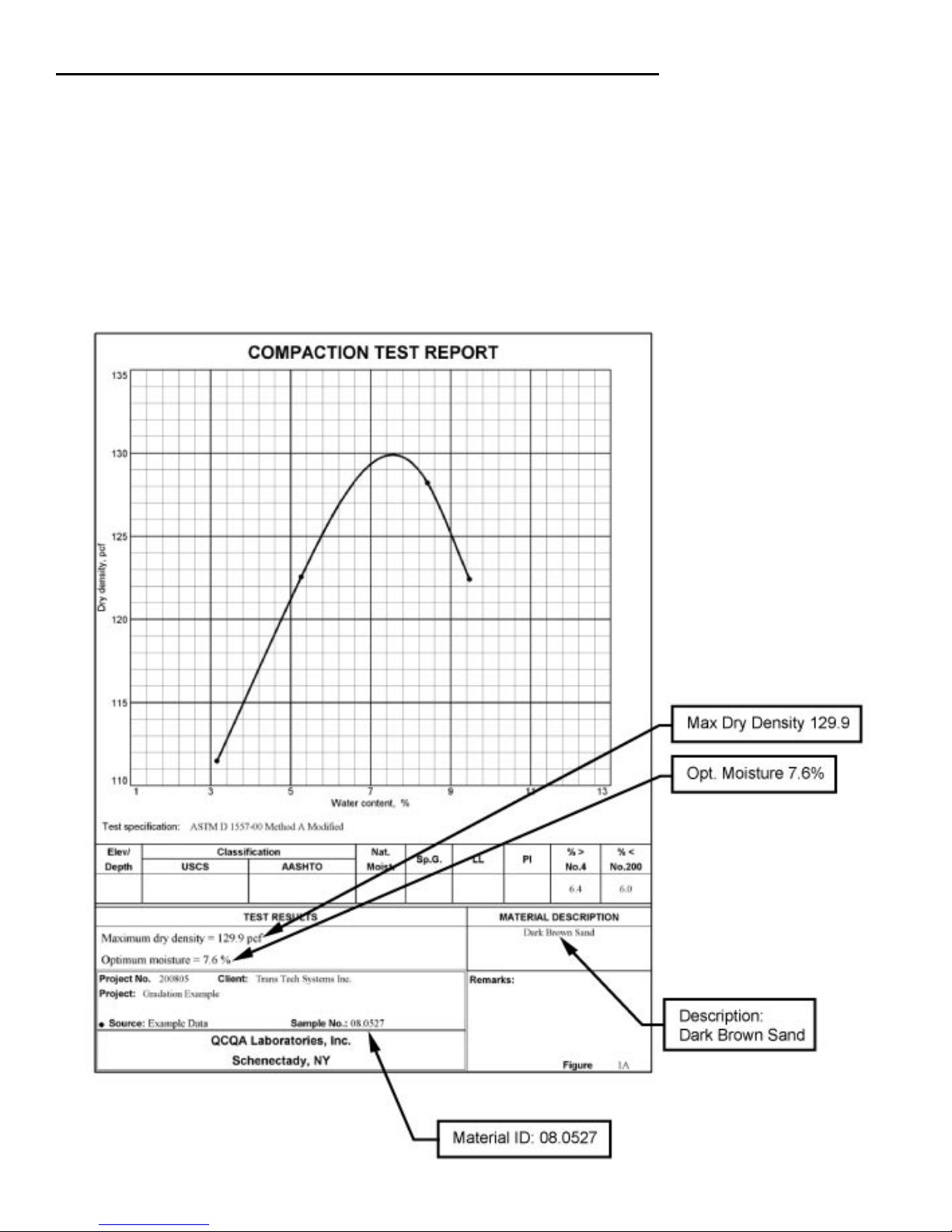
The Max Dry Density is the maximum practically achievable density a soil can have. This value is determined
experimentally by performing a “Proctor” Test (ASTM D 1557). 129.9 pounds per cubic foot is taken directly
from the example compaction test report.
The Optimum Moisture Content is the water content (%) at which the material can be compacted to its
maximum dry density. This is determined experimentally by performing a “Proctor” Test (ASTM D 1557).
7.6% is taken directly from the example compaction test report.
PL and LL are the plastic and liquid limits used to describe the plasticity of materials with a high silt and clay
content. They are determined by following the test procedure outlined by ASTM D 4318. This example is a
sandy material so PL and LL are input as 0.0. If plasticity tests had been performed on this material, the results
would be given on the gradation report.
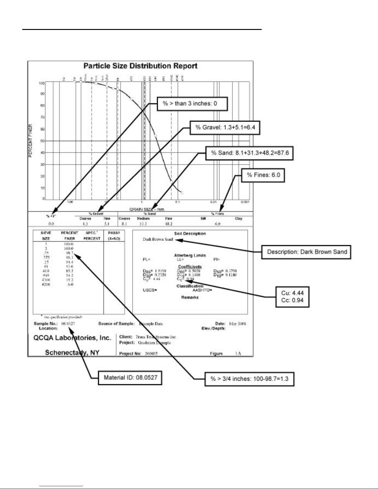
Cu and Cc are the Coefficient of Uniformity and Coefficient of Curvature of the material. They are calculated
values that are typically used describe the particle size distribution a soil. In this example, Cu = 4.4 and Cc =
0.94
% Gravel is the summation of the coarse and fine gravel in a sample of material. Some gradation test results
will report this as a single value while others will break it down into the coarse and fine fractions. The SDG
only recognizes the total percentage of gravel so the coarse and fine fractions will need to be added together
before entering them. The gradation report shown breaks the gravel content out into Fine and Coarse fractions
so those will need to be added together. 1.3% + 5.1% = 6.4%
% Sand is the summation of the coarse, medium and fine sand in a sample of material. Some gradation
test results will report this as a single value while others will break it down into the coarse, medium and fine
fractions. The SDG only recognizes the total percentage of sand so the coarse, medium and fine fractions will
need to be added together before entering them. The gradation report shown breaks the sand down into coarse,
medium, and fine fractions, so the percent sand in the example shown is 8.1% + 31.3% +48.2% = 87.6%.
% Fines is the summation of the silt and clay in a sample of material. Some gradation test results will
report this as a single value while others will break it down into the fractions of silt and clay. The SDG only
recognizes the total percentage of fines so the coarse, silt and clay fractions will need to be added together
before entering them. In this example, the percent fines is 6.0%.
37
Page 38
Part 7: Explanation of Gradation and Compaction Reports
% Greater than 3 inches is the percentage of the sample that is retained on the 3 inch sieve. Typical gradation
tests report the “percent finer” or percentage that passes a particular sieve. In this example the percent finer for
the 3 inch sieve is 100% so 0% of the sample is retained on the 3 inch sieve.
% Greater than 3/4 inch is the percentage of the sample that is retained on the 3/4 inch sieve. Typical
gradation tests report the “percent finer” or percentage that passes a particular sieve. In this example the percent
finer for the 3/4 inch sieve is 98.7% so 1.3% of the sample is retained on the 3/4 inch sieve.
38
Page 39
Part 7: Explanation of Gradation and Compaction Reports
!! Note: The sum of %Greater the 3 inches, %Gravel, %Sand, and %Fines must add up to 100%. The
default values programmed in the SDG software add up to 100%. As soon as one of those values is
edited, the sum will no longer add up to 100% and an error message will be displayed until all of those
gradation values are entered such that the sum is 100% again.!!
39
Page 40

Appendix A: Using the SDG MTL Generator
The SDG MTL Generator is a spreadsheet based application developed to determine the gradation inputs that
the SDG needs to measure moisture and density of a soil in cases when the gradation performed was not done
in accordance with ASTM D 422. The MTL Generator will allow users to input the gradation information that
they have and will produce a particle size distribution curve from which the Cu, Cc, %Gravel, %Sand, %Fines,
%>3/4” and %>3” values will be taken. Those values will be organized in a text file that can be uploaded onto
the SDG via a USB flash drive.
There are two MTL applications. One application allows users to input any sieve size, in millimeters, that
was used in their gradation. The second application is useful when an ASTM D 422 type gradation report is
available and users simply want to type the report summary into their PC and generate a text file to upload into
the SDG.
Getting Started:
The MTL applications are Microsoft Excel spreadsheets that contain macros. For the applications to operate
properly, Excel will need to be configured to run macros on any computer you wish to use these on. To change
the macro settings on your computer, follow these steps.
1. Open up Excel
2. Select the Tools menu
3. Select the Macro option
4. Select the Security option
5. Select the Security Level Medium and select OK
Once this setting is selected, Excel will ask you to confirm that you want to allow these applications to enable
macros each time they are opened. Choose enable macros when prompted to do so.
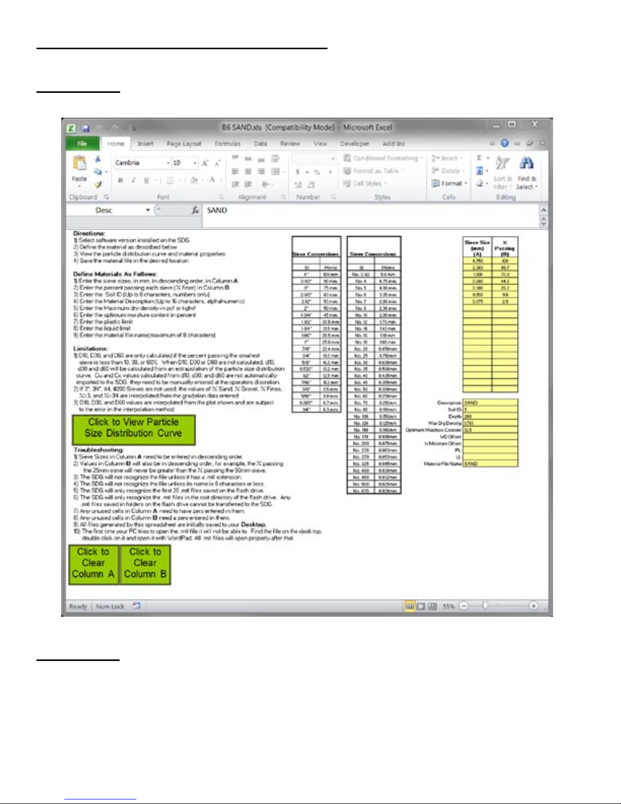
The Gradation Calculator has two separate screens. Screen one explains the use of the calculator, contains
conversion tables for US customary and metric sieve sizes, contains the inputs for the sieve sizes and percent
passing those sieves and has inputs for the material descriptors that make up the material definition file.
40
Page 41
Appendix A: Using the SDG MTL Generator
Screen One:
Screen Two:
The second screen of the MTL displays the plot of the particle size distribution curve and displays a table of all
of the material properties that will be converted into a text file to upload to the SDG.
On Screen 1, input the sieves used in the gradation (in mm) and the percent of material passing each sieve in
columns A and B. The data must be entered in order of decreasing sieve sizes, and the first sieve entered should
be of a size such that 100% of the material passed that sieve.
41
Page 42

Appendix A: Using the SDG MTL Generator
Screen Two:
Once the gradation data is entered, fill in the rest of the material definition information in the yellow cells on
Screen 1. The explanations and limitations for those definitions are explained on Screen 1.
Clicking on the button to view the Particle size distribution curve displays Screen 2. The gradation curve will
be visible, as well as a table of all of the properties that define the material. Clicking on the button to save and
view the material properties file creates a text file with a .mtl extension of your PC’s desktop. (Note: the first
time you open a .mtl file on your PC, you will need to manually open it from the desktop with WordPad
or similar text file editor. After that, your PC will always open .mtl files automatically.)
The .mtl file can now be copied to a USB flash drive to be uploaded onto the SDG as explained on page 18.
The SDG will only recognize the first 20 .mtl files on the USB flash drive, and it will only recognize them
if they are in the root directory of the flash drive. If .mtl files are in sub folders on your flash drive, the
SDG will not recognize them.
42
Page 43

Appendix A: Using the SDG MTL File Tool
The MTL File Tool is designed to allow users to easily create .mtl files to upload into the SDG. If a gradation
report completed in accordance with ASTM D 422 is available, all of the information on that report can be
entered into the table on the Gradation file tool and a .mtl file will automatically be generated and saved to the
Desktop of your PC. This file can then be transferred to a USB flash drive and installed directly into the SDG
as explained on page 18.
43
Page 44

TransTech Systems Product Warranty
The Company warrants to the Purchaser that the product delivered hereunder will be free from
defects in material or workmanship and be the kind and quality designated or specified in the contract
or purchase order. This warranty shall apply only to defects appearing within one (1) year from the
date of shipment by the Company.
If the product delivered hereunder does not meet the above warranty and if the Purchaser promptly
notifies the Company, the Company shall thereupon correct any defect, including nonconformance
with the specifications, either (at the Company’s option) by repairing any defective or damaged parts
of the product, replacing the product, or by making available the necessary repaired or replacement
parts.
The liability of the Company under this warranty, for any loss, whether the claim is based on contract
or negligence, shall not in any case exceed the cost of correcting defects in the product as herein
provided, and upon the expiration of the warranty period, all such liability shall terminate. The
foregoing shall constitute the exclusive remedy of the Purchaser and the exclusive liability of the
Company. The foregoing warranty is exclusive and in lieu of all other warranties, whether written, oral,
implied or statutory.
No warranty of merchantability or of fitness for purpose shall apply. Unauthorized service shall void
this warranty.
TransTech Systems Product Non-Warranty Return Policy
Non-warranty returns for TransTech Systems Inc. products must be made within twenty (20) days
from the original date of shipment, unless otherwise indicated. Returned products must be in the
original packaging, unused and in undamaged condition. Proof of purchase is required. Upon receipt
of the product TransTech will inspect the product to the above mentioned criteria.
Unused products will be issued a credit to the Purchaser’s account that was used to purchase
the product. TransTech will not credit prepaid shipping cost. The original packing slip or invoice is
required to be sent back with the product to be returned.
The Purchaser is responsible for shipping the product back to TransTech, carefully package the
item(s) and include the packing slip and return manufacturing authorization number on the package.
Prepay shipping is required – TransTech will not accept C.O.D.s.
Returns will be credited within 10 working days.
Proper Process of Warranty or Non-Warranty Shipments to TransTech Systems
For product returns (warranty or non-warranty), please follow the instructions below to assure prompt
handling:
Call us for authorization (518-370-5558 or 800-724-6306), obtain a return manufacturing authorization
number (RMA), and the return shipping address.
Indicate to our representative the reason for returning the product.
For Warranty Returns, Purchaser is responsible for shipping to TransTech’s office. TransTech will pay
ground shipping return to the Purchaser.
44
Page 45

Notes:
45
Page 46

Notes:
46
Page 47

Notes:
47
Page 48

 Loading...