

Page 1

Pavement Quality Indicator
Model 301
Page 2

2.0 Controls and Components
4
4
3
7.0 Warranty
FAQ’s
Page 3
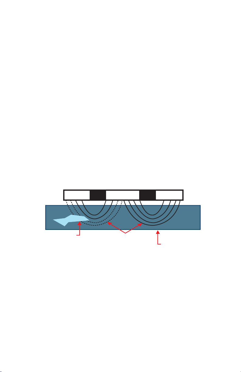
TransTech’s third generation Pavement Quality Indicator™ (PQI)
utilizes state
primary features are:
moisture.
The density of asphalt pavement is directly proportional to the
measured
uses electrical waves to measure dielectric constant using an innovative, toroidal
PQI convert the field signals into material density readings and displays the
results. Once calibrated direct density readings can be consistently obtained.
This handbook is intended to be both a training manual and a
reference source
for the operation, care and maintenance of the TransTech Pavement Quality
Indicator. You must read through the entire manual completely to familiarize
yourself with the unit’s features, controls and operating modes before starting to
take readings and analyze data.
The PQI is intended primarily for use on newly-laid asphalt
pavements with lift
thickness ranging from 1 inch to 6 inches. Once calibrated the PQI will provide
reliable and consistent density measurements.
Page 4
Every effort has been made to make the Pavement Quality Indicator
to use and inherently safe. The PQI uses no nuclear elements, and is instead
based on a safe, low-voltage direct current electrical measurement techniques.
Like any instrument, however, the user should exercise care and common sense
in its use to prevent mishaps.
Warning- Do not use the unit on or near exposed electrical wiring. A shock
hazard potential exists if contact is made with the exposed wiring.
Warning-
Use care in handling the unit. Personal injury can occur through
improper handling. Take proper precautions to prevent accidental dropping of
the unit.
Caution- Turn the unit off when not in use and during transport.
Caution- Unauthorized disassembly of the unit will void the warranty.
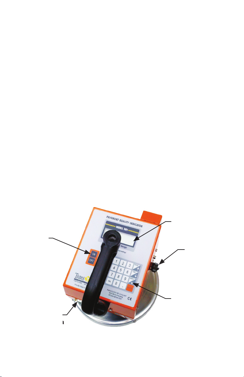
2.1 External Controls and Components
Prior to learning how to operate the PQI, we recommend that you
familiarize
yourself with the PQI unit’s operating controls and components. Illustrations and
listing of the main components and their basic functions are shown below.
Display
3
Page 5

2.2 Receipt
The PQI shipment package includes the items listed below. Report
12 VDC - Fast Charge
2.3 Charging The Battery
Important- Before using the unit for the first time the internal battery must be
fully charged. Follow the unpacking and setup instructions below.
The third generation PQI unit is powered by nickel metal hydride
batteries
which weigh less and are smaller than equivalent lead-acid cells. The new
microprocessor controlled battery charger will usually charge the PQI unit
in a couple of hours. For first use and after a fully discharged battery pack a
minimum of 5 hours should be allowed
for charging.
Under normal operation, the PQI unit can operate in excess of 13 hours
Warning- Attempting to recharge the unit in any other way than with the
recharger
supplied with the unit can result in damage to the unit and can present
a safety hazard. Use of any charging means other than the recharger supplied
with the unit will void the unit’s warranty.
The figure below shows the battery charger supplied with the PQI.
Page 6

PQI unit.
4. When charging is complete, unplug the charger from the power source
first then from the connector on the PQI unit.
Battery Voltage is displayed on the Continuous Reading Mode Screen. A fully
charged battery will read approximately 12.9-13 volts. The battery voltage will
go down as the PQI is used. At 11.5 volts, it is time to get the PQI re-charged.
When the PQI voltage gets to 11.0 volts, the PQI will display a “low battery
warning” and will not take any further readings. It is important to re-charge the
battery after each use.
3.1 General Operation Overview
The Pavement Quality Indicator is designed to be an extremely flexible
unit,
with several useful modes of operation. Each mode of operation is accessed
through the keypad controls. The number, letter and arrow keys have several
functions. The immediate function is shown by the text in the display panel.
The display can show four lines of text at a time called a page. The display tells
the operator what the PQI unit is ready to do or indicates that a reading is being
taken or that more key setting information is needed from the operator. Pressing
TransTech Systems
PQI V3.3ae1
Initializing………
Figure 3.1 first or “bootup” screen display.
Page 7
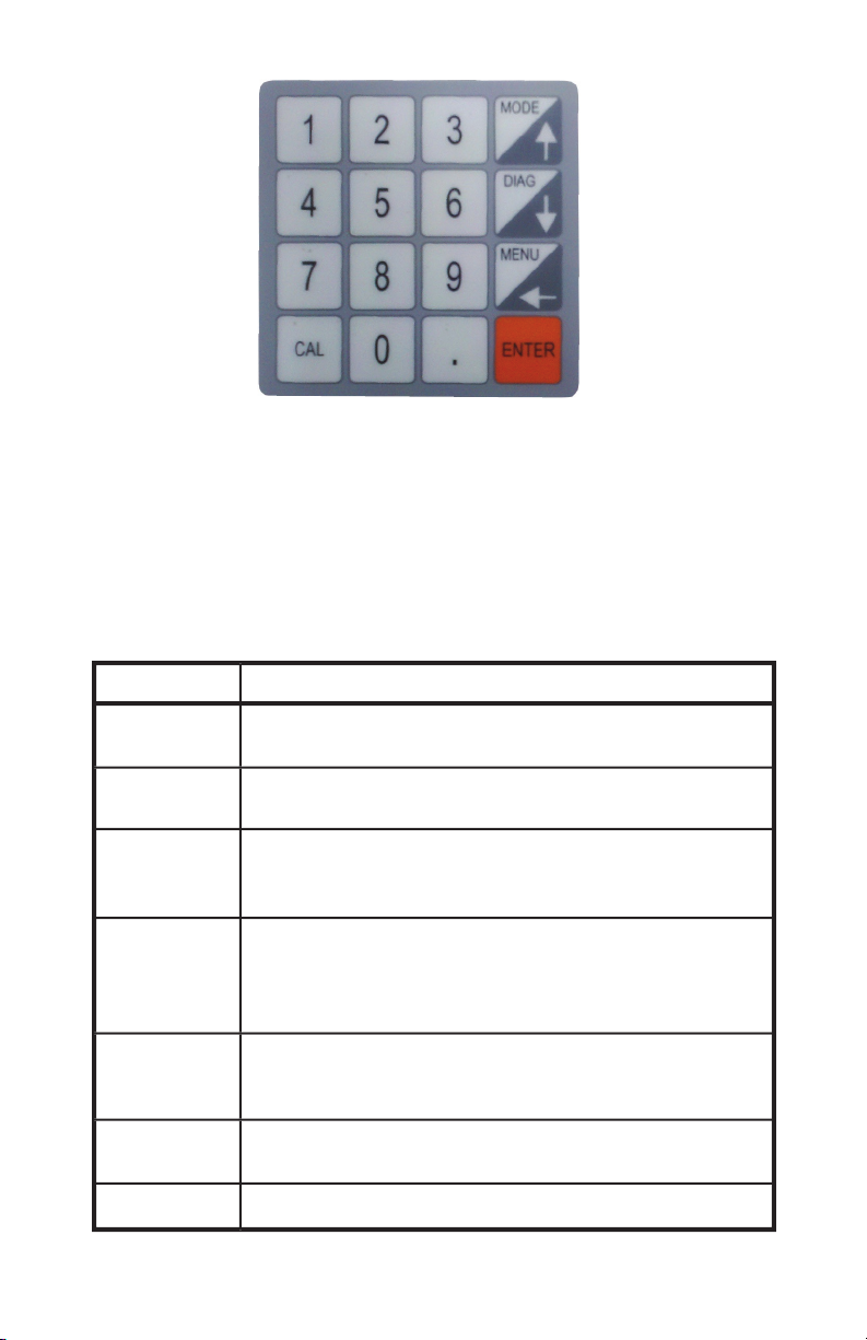
Figure 3.2 Keypad
A summary of the keypad codes used to set date and time, change measurement
modes, enter values for the Maximum Theoretical Density (MTD) value and
following sections of this handbook.
Function
The number keys have different
upon the menudisplay.
Mode/↑
Used as to switch among the four
measurement
modes or to scroll in the up direction.
Diag/↓
Used to display the DIAGNOSTICS
in the down direction.
Menu/←
This key brings the unit back to the
MAIN MENU.
Works as a back space key when it’s necessary to
Enter
The ENTER key functions like a return key
in that
it tells the PQI unit to accept information or to take
Used to enter calibration mode when in one
measurement modes.
Works as a decimal point when entering
values.
Page 8

3.2 Starting and Self Test
Important
Before using the unit for the first time the internal battery must be fully charged.
Follow the setup instructions in Section 2.2 above.
3.2.1 Starting the PQI unit for the first time.
A.
Turn the PQI on by flipping the POWER switch. After a few seconds
the
display will show the TransTech boot up screen. After the boot up screen
clears the PQI will display the SELECT PAVEMENT TYPE screen. From the
main menu option #2 also allows changing of this setting. The selection of a
“Pavement Type” / stone size in the mix which the PQI is going to be used on
is required as part of the initial calibration of the unit.
B.
The PQI will prompt the user for the correct unit of measurement
inches or mm. The PQI 301 asks the user to input the depth of the pavement
being laid out by the paver.
Lift Thickness
Enter Units
Lift Thickness
Enter Thickness ( in or mm)
Press the number 1 to show the first page of the MAIN MENU (also called
setup menu). Press 2 to return to an operating mode if setup was performed
earlier in the day.
Page 9

ENT) Exit (Scroll)
D.
Press the Down arrow to show the second MAIN MENU page.
4) Data Log
ENT) Exit (Scroll)
E.
Press ENT) Exit or (Scroll) Press the Down arrow to return the display to the
first page of the MAIN MENU as above.
3.3 Setting the Date and Time
The following steps check the date and time of the clock inside the PQI.
At the
first screen of the MAIN MENU, pressing the 1 key enters the Date and Time
mode.
ENT) Exit
3.3.1 Setting the Date
A. Pressing the 1 key prepares the PQI for setting the month, day and
year. The
first line of the display indicates the date presently stored in the PQI. If this date
MENU.
Enter Date
MM/DD/YYYY
XX/XX/XXXX
ENT) OK “.” ) Cancel
The MM is the first portion of a two digit month representing the 12 months of
the year. For example 01 is January.
Page 10

The DD is the second portion of a two digit day indication with a value from 01
to 31.
The YYYY is the third portion of the date representing a four digit year.
For
B.
Notice the flashing cursor beneath the MM letters. Using number keys
enter the value for the current month, 01, 02, etc. At this time using the
(backspace) key will move the cursor between the two MM spaces so
that the month value can be changed.
See that the underline cursor has moved to the DD position. Using
number keys enter a two digit value for the current day of the month,
01, 02, etc. Using the ← (backspace) key will move the cursor between
the two DD spaces so that the day value can be changed if a mistake is
made.
D.
The underline cursor has moved to the YYYY position. Using number
keys, enter a four digit value for the year. Using the ← (backspace) key
will move the cursor between the four spaces so that the year value can
be changed if a mistake is made. Pressing the ENT key sets the new
date. Pressing the “.” key cancels and returns the PQI to the change
date or the time screen without making any changes to the current
date.
Option #3 “Date Format” allows the date format to be changed from
M/D/Y to D/M/Y.
3.3.2 Setting the Time
A. From the Main Menu press the 1 key. Press the 2 key and the PQI is
ready
to have the time set. The HH is the hour portion of the time in a 24 hour format
Enter Time
HH:MM:SS
XX:XX:XX
ENT) OK “.” ) Cancel
The MM is the minute portion of the time display with a range of 00 to 59
minutes.
The SS is the seconds portion of the time also with a range of 00 to 59 seconds.
B.
See that the underline cursor is under one of the HH letters. Use number
keys to enter the new hour of the day. Using the ← (backspace) key will move
the cursor between the four spaces so that the year value can be changed if a
mistake is made.
Page 11

The underline cursor has moved to the MM letters. Use the number keys
to enter a new minute value. Using the ← (backspace) key will move the cursor
between the two paces so that the minute value can be changed if a mistake is
made.
D.
The underline cursor has moved to the SS letters. Use the number keys to
enter the new seconds values. Using the ← (backspace) key will move the
cursor between the two spaces so that the seconds value can be changed if a
mistake is made.
E.
Pressing ENTER sets the new time. Pressing the “.” key cancels and returns
the PQI to the change date or time screen without making any changes to the
current time. Pressing Enter returns the PQI to the Main Menu Screen
ENT) Exit (Scroll)
3.4 Setting the Mix Information
A. From the MAIN MENU press the 2 key.
ENT) Exit
3.4.1 Setting the MTD value
The Maximum Theoretical Density (MTD) value is provided from the asphalt
mix designer.
A.
Pressing the 1 key prepares the PQI unit to accept or change the current MTD
value.
B.
Pressing the 1 key will return the display to the Mix Information MENU
without any change to the stored MTD value. Pressing the 2 key changes the
display to the Set MTD menu.
Page 12

At this display, if the ENTER key is pressed a 0.0 MTD value will occur and
the display will return to the Main Menu.
D.
Use the keypad to enter a new 4 digit MTD value. At this time the
key can
be used to back space and change any of the digits. When the new MTD
value is set pressing the ENTER key sets the new MTD value in the PQI. The
display will return to the M ix Information Menu. The “.” key is used to enter
the decimal point.
3.4.2 Setting the Lift Thickness
A.
Pressing the 2 key prepares the PQI unit to accept or change the current Lift
thickness value.
New:
Lift Thickness
Enter Thickness (in)
At this display, if the ENTER key is pressed a 0.0 Lift Thickness value will
B.
Use the keypad to enter a new Lift thickness value. At this time the
key
can be used to back space and change any of the digits. When the new value
is set pressing the ENTER key sets the new Lift value in the PQI. The display
will return to the M ix Information Menu. The “.” key is used to enter the
decimal point.
3.4.3 Setting Pavement Type
A.
Pressing the 3 key prepares the PQI unit to accept or change the current
Pavement Type.
Page 13

At this display, choose option 1,2, or 3 depending on the type of pavement/stone
Information Menu.
Pressing
ENTER
returns the PQI to the Main Menu Screen
ENT) Exit (Scroll)
3.5 Changing Displayed Units
A.
From the MAIN MENU press the 3 key.
ENT) Exit
At this display, by pressing the corresponding #, the unit of measurement will be
Item 3 allows you to set the PQI to read % compaction or % voids. depending
Using the PQI on the road
take it out onto the road and perform a simple calibration.
Page 14

3.6 Calibration
be calibrated for each asphalt mat at each job site. The PQI determines
HMA density by measuring a property of the HMA mat and comparing it
to a measurement of that property at a known density. The property that the
PQI measures varies for different HMA mixes. Therefore, to obtain accurate
measured. Once calibrated for a specific mix, the calibration factors (called
used again.
The PQI provides a number of different calibration methods which can be used
under different circumstances. The following table briefly describes the different
methods:
Method
Description
Normal
PQI readings have been taken and cores have
been obtained from those reading areas. Simply
high or low relative to the core readings.
taking a reading of the unrolled mat and
that point.
Two Point Method
by taking readings of the unrolled mat and a
peaked area of the finished mat entering the
Manual Slope
Allows you to type in a numeric value for the
ENT) Exit
To access the calibration methods, press the “CAL” key while the PQI is
Page 15

3.6.1 Preparation
Pick a location on the asphalt that is dry. Designate an area approximate 10 feet
long and 5 feet wide on the asphalt mat. Divide the area into five data locations.
3.6.2 Calibration Readings
Use the PQI in the Single Reading Mode.
Place the PQI in the first location on the asphalt mat. Using a crayon marker
Press the ENT key,
and wait for a reading to
HINT: Better readings are taken if no hands or objects are in contact with
the PQI.
Move the PQI approximately 2 inches up and to the right on the outside of the
Move the PQI clockwise around the marked circle to about the 4 o’clock
position. Press the ENT key to take another reading and record it in the table.
Following the pattern in Fig. 3.6.2, move the PQI to the next circle location,
record a density reading in the center and at each clock position, in turn, until the
table is complete.
Figure 3.6.1 Reading Location Layout
Figure 3.6.2 PQI Measurement Pattern
Page 16

3.6.3 Calibration Comparison
A.
Arrange to have physical core samples taken from the center of each marked
circle location in the 10 foot strip.
B.
Enter the density value from each core sample on the data table.
Calculate the numeric difference between the average PQI readings and the
core density lab reports. Add or subtract to obtain a small number which
represents the difference between the density value that the PQI is reading
versus the actual density values from the core samples. These numbers are
used to adjust the calibration offset value stored in the PQI so that the unit
can indicate readings that are very close to the actual density values for the
asphalt mix at the job site.
From the Calibration Menu, press ‘1’ to access the normal calibration function,
which will display the following screen:
ENT) Exit
The function is used when you have obtained a number of PQI readings,
PQI is reading too high or low. The first step is to press a key to indicate whether
the PQI is reading too high or low. After pressing the key, the following screen
will appear:
Adjustment:
At this point you should enter the difference in the PQI and core readings.
For example, if the average core reading was 142.3 lb/ft3 and the average PQI
reading at those locations was 143.1 lb/ft3, then the PQI is reading 0.8 lb/ft3 too
high, relative to the cores and you would enter “0.8” or “.8” at the “Adjustment”
prompt.
Note that the calibration should be entered in the current density units. If
the PQI is set to kg/m3, the adjustment should be entered in to kg/m3.
Page 17

After entering the adjustment, the following screen will be displayed to confirm
your entry. The adjustment amount you entered will be shown (the value will
be negative if you said that the PQI was reading too high), along with the new
Adjustment = -1.0
New Offset = -1.0
If you choose option #1 the new offset will be saved in the PQI.
The PQI is now calibrated using this method.
Note: You must first enter the mix MTD before using this method.
Many users have found that their screeds obtain a fairly uniform compaction. If
this compaction is known, it can be used to perform a quick offset calibration of
the PQI using the One Point Method. To use this method, first press ‘2’ (Special)
from the Calibration Menu. After displaying a message recommending that you
first read this guide, the following menu will be displayed:
ENT) Exit
After entering ‘2’, to select the One Point Method, you will be prompted to enter
the expected percent compaction as follows:
Enter % Compaction
After entering the percent compaction you expect from the screed, you will be
prompted as follows:
Page 18

Place PQI on
Unrolled Mat
At this point, you should place the PQI on a fresh unrolled portion of the mat,
press the ENT key, and remove your hand from the PQI. Follow the pattern in
figure 3.6.2 in order to obtain 5 readings. After the 5th reading the PQI will
keep the old offset.
The Two Point Calibration Method is similar to the One Point Method but
it uses an additional measurement of the finished mat in order to obtain a
instructions for performing the calibration and entering the readings.
Note:
The worksheet calls for a reading to be taken on a finished (or “peaked”)
followed:
Reduce the water spray on the roller to the minimum setting
2.
Allow the roller to pass by the sample location
3.
Place the PQI on the mat in a visibly dry location and mark the location for
reference
4.
Take a PQI reading and record the density value
Pick up the PQI and check the probe bottom for signs of moisture
If moisture is present, wipe off the bottom of the probe
7.
Have the roller roll back over the location and begin the next PQI
measurement
Continue this process until the density reading on the PQI dose not rise any
further and has reached its peaked value.
Page 19

Manual Slope (Factory Use Only)
The Manual Slope Method allows you to type in a numeric value for the
was previously calibrated because you can simply reenter the slope that was
previously used.
The first line will be either “Set D_Slope” or “Set S_Slope”, depending on the
lift thickness that you entered. The second line displays the current value of the
To enter a new slope value, presumably a value that you recorded the last time
the mix was used), press ‘2’ and enter the new value as instructed. The new slope
value will be used immediately when you return to one of the run modes.
3.7 The Operating Modes
Average, Single, and Segregation. If the PQI is not in one of the run modes (e.g.
it might be displaying the Setup Menu), you can switch to the last Run Mode
used by pressing the ‘Mode’ key. If the PQI is already operating in one of the
run modes, pressing the ‘Mode’ key will cause the PQI to switch to the next run
mode.
The PQI also has a Diagnostics Mode, which is primarily used by factory
personnel. You can switch to Diagnostics Mode by pressing the ‘Diag’ key.
Each of the run modes will be described in the following sections.
3.7.1 Continuous Reading Mode
Page 20

Batt: 12.7V
H2O: 3.2 187.6 F
D: 156.5 Lb (87.8%)
Line 1:
Always reads “Continuous Mode”. [ ] Indicate pavement type selected.
Line 2:
Displays the battery voltage. A fully charged battery will usually read
approximately 13.8 V and the voltage will decrease as the battery is
discharged. The PQI should be recharged if the battery voltage is less
than 11.6 volts. If the battery voltage is less than 11.0 volts the PQI will
stop operating and simply display a “Battery Low” message.
Line 3:
Displays the moisture index and the mat temperature.
The moisture
index gives a relative indication of the amount of moisture in the mix or
on the surface of the mat.
Line 4:
Displays the density in actual units and in percent.
The density will be
displayed either in lbs/ft3 or kg/m3.To change the units, go to the
Setup Menu and select ‘Displayed Units’ and the select ‘Density’. The
percent density will be displayed in either percent compaction or percent
voids. If displaying percent compaction, the value will be enclosed in
“( )”. If displaying percent voids, the value will be enclosed in “[ ]”.
To change between these units, go to the Setup Menu and select
‘Displayed Units’ and the select ‘%’. Remember that the percentage
values will not be accurate unless you have properly entered the MTD
value of the mix you are currently measuring.
If the PQI is running in Continuous Mode and no keys have been pressed for
the last 5 minutes, the PQI Mode will enter a Power Save Mode. Much of the
Note: While the PQI will take continuous readings in Continuous Mode, the
readings are only valid when the PQI is properly positioned and the
operator is not touching the PQI.
3.7.2 Single Reading Mode
The single reading mode takes a density reading within five seconds. This mode
requires the Enter key to be pressed to start each reading. When the PQI is not
to the Continuous Mode.
Example of Continuous Mode Screen
Page 21

Single Mode
Press ENT to Read
Example of Single Mode Screen
3.7.3 Average Reading Mode
The average reading mode allows the PQI to perform calculations to determine
the average density of five readings from one location on the mat. This mode
hold 99 average readings with station location information along with time and
Avg Mode (5)
ENT) Take Reading # 1
Eample of Average Mode Screen
A.
Press
Enter
B.
Move the PQI and follow the instructions on the display for the next reading.
(Press Enter to start next reading)
After reading number 5 is complete press
Enter
to have the PQI calculate the
Avg Mode (5)
ENT) Display Average
H2O: 3.2
D: 156.5 Lb
The next screen displays the average of the 5 readings and indicates that the PQI
is ready to be moved to a new location for the next density reading. The PQI will
20
Page 22

Avg Mode (5)
ENT) Continue
H2O: 3.2
D: 155.5 Lb
Log the last avg?
Logging the average allows the user to enter a station location.
For example;
the Station Number from a site map may be give as “300 + 050.“
Enter 300 as the first# press
Enter
key can be used to “backspace” and correct numbers. Put in the numbers for the
Enter
Bypass the Set Location screen by pressing
Enter twice
Enter Station #
Example: 300 +50
First #:
Data Added to Log
Press any key
Note: If you choose not to log an average the PQI returns to the first
Average Mode screen and is ready to begin a new set of readings.
3.7.4 Stored Data
From the MAIN MENU press the Down arrow until the screen below appears.
4) Data Log
ENT) Exit
Page 23

Press Key 4 once to display the DATA LOG CONTROL screen
ENT) Exit
Warning!!!! Pressing key 1 will clear all the readings from the Data Logger
Press key 2 to view all the data in the data log on the PQI display screen.
Data Log Size: 22
Up/Down to select
ENT to exit
Pressing the Up or Down arrow keys displays the previous or next set of
readings.
Loc 0300+0150
H2O: 3.1
T:186.4
DENS: 156.7Lb
Pressing the
Enter
key returns the display to the previous menu.
3.7.5 Segregation Mode
finished mat. The PQI’s Segregation Mode can be used to conveniently measure
the density variations that result from mix segregation.
The operation of Segregation Mode is patterned after test procedures used by a
number of testing organizations. The PQI is used to take a number of readings
Page 24

The first screen you will see in Segregation Mode appears as follows:
The code at the end of the first line tells which location and reading are about
to be performed. For example, the “1A” on the previous screen indicates that
you are at the first location and are taking the first, or ‘A’, reading there. Two
readings (‘A’ and ‘B’) are taken at each location and the average value is used.
Taking the average of two readings is required for nuclear gauges, which exhibit
poor repeatability. The PQI has excellent repeatability so two readings should
not be required, but two readings are taken for compatibility with existing
nuclear test procedures.
4) Wait for the reading to be taken (this will take approximately 5
seconds).
After the reading has been taken, the screen will appear similar to the following
H2O 2.7
D: 147.4Lb
take reading “1B”, the second reading at location #1. After accepting the reading
After you have taken all the readings, press ‘2’ to calculate the results. The
results will be displayed on a screen similar to the following:
Results
Lo: 142.7lb
23
Page 25

From this screen you can press ‘1’ to display the lowest density reading, highest
readings can also be transferred to a personal computer using the PQI’s Remote
Mode).
Pressing ‘2’ will complete the set of readings and display the starting screen with
the location/reading reset to ‘1A’.
Correction
3.8.1 Moisture correction
The third generation PQI has a built in moisture correcting formula. Care should
Excessive moisture can affect the accuracy of the PQI. DO NOT take a reading
where there is signs of excessive surface moisture, ie puddles. The Relative
Water Value is displayed as “H2O” in all measurement modes of the PQI.
The third generation PQI has a built in moisture correcting formula. Care should
Batt: 12.7V
H2O: 3.2
D: 156.5 Lb
Example of H2O being displayed
The PQI shows H2O values up to three digits.
Hint: Always wipe the sensor disk with a clean dry cloth before taking
another reading.
3.8.2 Automatic Temperature Compensation
The third generation PQI comes equipped with an infrared temperature probe
the asphalt mat.
Temperature readings are displayed during all of the measurement modes.
Batt: 12.7V
H2O: 3.2
D: 156.5 Lb
Example of temperature being displayed
Page 26

3.9 Power Save Mode/Auto Shutoff
The PQI Model 301 has a built in power saving mode when using the PQI in the
the unit will go into a power saving mode. Pressing any key will “Wake” the
PQI up for continued use. If the PQI is left “On” for an extended period of time
without any keys being depressed, it will shut itself down, to conserve battery
run time.
4.0 Remote Mode
The PQI has a remote mode which allows you to connect it to a personal
Mode readings. To enter Remote Mode, choose selection #6 on the Setup Menu.
To exit Remote Mode, press any key on the PQI keypad.
with a serial (COM) port and terminal emulation software, such as Windows
HyperTerminal. Using a suitable nine-pin serial cable, you should first connect
the PQI to one of your personal computer’s serial ports, making sure to note
which port (e.g. COM1, COM2, etc.).
After connecting the cable, start the communications program on your PC. The
program should be configured to use the COM port that you connected to, with
the following parameters:
Baud Rate:
Data Bits:
Parity:
None
If you are configuring Windows HyperTerminal, you would first select
have connected to. Then select “Configure” to display the remaining parameters.
25
Page 27

Clear (erase) the PQI’s Data Log
N:
Print the number of entries in the PQI’s Data Log
L:
Print all Data Log entries in a readable format
X:
Print all Data Log entries in a spreadsheet-readable format so the
data can be easily imported into a spreadsheet such as Microsoft
Excel.
Print the last set of readings taken in Segmentation Mode.
Enter a new title for the PQI. The title is displayed on the PQI when
power is first applied. To change the title, type ‘T’ and then type the
title. This is a simple title entry function and backspacing is not
allowed. If you make a mistake, you must reenter the correct title.
H:
Print a list of all the commands
E:
Instruct the PQI to exit Remote Mode.
is suggested that 5 or more readings be taken at each site following the reading
pattern of Fig. 3.6.2 .
For accurate readings, the PQI should have a clean, dry, smooth interface with
the mat. Therefore, you should wipe the PQI probe surface dry and clean after
would prevent the PQI from seating properly. If a buildup of asphalt begins to
form on the probe surface, clean the surface with WD-40.
While the PQI contains moisture correction algorithms, the most accurate
readings will be obtained if areas with low moisture levels are measured. If a
measurement area has noticeable surface moisture, you should either wait for the
moisture to evaporate or remove the moisture with an absorbent cloth.
26
Page 28

Watch for suspicious readings
If a reading seems unusual or suspicious, check for possible measurement
Best results are obtained when moisture levels for a series of readings are kept
relatively constant. If the moisture level for a reading is more than a percentage
point higher or lower than the previous readings, the reading should be treated as
Don’t touch the PQI while it is making a measurement
Touching any part of the PQI while it is performing a measurement can distort
the reading.
The PQI measures percentage of air voids in the area beneath the probe,
including the voids on the surface of the mat, while the AASHTO T-166 specific
the AASHTO T-166 method is measuring, PQI readings should be taken on
when the PQI is used on mixes containing larger aggregate.
Measurements should be made on the same day as paving
While the PQI has corrections algorithm for surface moisture, embedded
moisture which can occur after periods of rain, can adversely effect the PQI
readings. If you need to take PQI readings at exact coring locations and the cores
PQI readings on the day of paving.
Page 29

The PQI has been designed to require a minimum of maintenance or service.
Normal care in use should insure long and trouble free operation. The bottom of
the sensing probe is protected by a durable bottom. This material was chosen as
it is resistant to adhesion of pavement particles. If pavement materials begin to
The chart below provides guidance to a few suspect conditions.
Trouble Shooting Chart :
Problem
Incorrect Screen Display
Turn unit off and then back on (Reset)
Incorrect Density Reading
Battery Problems
Data is not being recorded
Review Data Logger procedure
28
Page 30

In the event that the PQI continues to malfunction an internal diagnostics mode
warranty period will void the unit’s warranty. From the
Main Menu option #5
is a diagnostic tool for factory use.
The Company warrants to the Purchaser that the product delivered hereunder
will be free from defects in material or workmanship and be the kind and quality
the Company.
If the product delivered hereunder does not meet the above warranty and if
the Purchaser promptly notifies the Company, the Company shall thereupon
product, replacing the product, or by making available the necessary repaired or
replacement parts.
The liability of the Company under this warranty, for any loss, whether the
whether written, oral, implied or statutory.
No warranty of merchantability or of fitness for purpose shall apply.
Unauthorized service shall void this warranty.
Factory authorized service and replacement items may be obtained directly from
TransTech’s factory or through an authorized representative.
For further information contact TransTech Customer Service:
Fax
E-mail
inquiries@transtechsys.com
Address
29
Page 31

Date
Job Site
Asphalt Mix
MTD Value
Core Comparison Calibration Work Sheet
PQI Readings
Avg. PQI Readings
Avg. Difference between cores &
PQI readings (Calibration Adjustment) value
Position Location1 Location2 Location3 Location4 Location5
4 o’clock
Average
by 5)
30
Page 32

PQI 301 Two Point Calibration Worksheet
FACTORY USE ONLY!!!!!
Enter MTD in PQI and record here
Display the Setup Menu either by
Startup Menu or
Run Mode
4. Press ‘2’ to “Enter a New Value”
Use the PQI’s Average Mode to obtain a low-density measurement from
repeated “Density Mismatch” errors, switch the PQI to Continuous Mode (by
pressing the ‘Mode’ key) and retake the reading. Record the reading here
Use the PQI’s Average Mode to obtain a high-density measurement from a
finished area of the mat. Record the reading here
To compute slope, the PQI requires an estimate of the actual percent
compaction behind the paver. This density is typically 82% of MTD but may
vary with mix and with paver type. In the following table, enter your estimate
To compute slope, the PQI also requires an estimate of the actual percent
compaction of the finished mat where the finished reading above was
taken. This density is typically 95% of MTD but may vary with mix. In the
following table, enter your estimate of percentage of MTD you would expect
in the finished mat.
Use the PQI Slope Calibration Function
4. Enter “Lo Reading”, “Hi Reading”, “Lo Estimate” and “Hi Estimate”
values from above when prompted
7. Press ‘Ent’ twice to return to Run Mode
Low
Reading
High
Reading
Low
Estimate
High
Estimate
New
31
Page 33

Worksheet to Calculate MTD
Density
Targets
Enter Maximum Theoretical,
rice gravity in (A) Lab values are
commonly in gcc ( i.e. 2.54)
3
pounds per cubic
foot ( i.e. 158.50) (A) x 62.4
Enter Density Target (B) In PQI
“See Entering
MTD in Manual”
32
Page 34

Is the PQI orange carry case watertight?
No, the case is not watertight and should not be left out in the rain.
2.
No, There are no user serviceable parts, it must be sent back to the
factory.
3.
Do you have to calibrate the PQI annually at the factory?
No, unless you experience a problem with the unit it does not need
to be sent back.
4.
At this time the PQI 301 is only designed for use on Asphalt Pavement.
How can I charge the PQI 301 in my car?
We suggest that you purchase a 12 volt DC to 120 volt AC power
inverter from a local retailer and plug the PQI charger into the inverter.
Follow the inverter instructions.
33
AC Charger
www.transtechsys.com/opencart
mobile device to go
Page 35

34
4000-0021
Vehicle Cord
www.transtechsys.com/opencart
Page 36

 Loading...