

Page 1

USER MANUAL
iPOSTER
Indoor series:P2.5/P1.9
Page 2
1
Index ························································································································································ 1
Safety information ······························································································································· 2
Specification ·········································································································································· 7
Installation ··········································································································································· 10
Serviceability ······································································································································· 11
Accessories ·········································································································································· 12
Package ················································································································································· 15
Control system ··································································································································· 16
Maintenance & Repair ····················································································································· 63
Index
Page 3
2
The following symbols are used to identify important safety information on the
product and in this manual:
Safety information:
WARNING!
Read the safety precautions in the section before installing,
powering, operating or servicing this product.
WARNING!
Safety hazard.
Risk of severe
injury or death
WARNING!
Refer to
manual before
installing,
powering or
servicing
WARNING!
Hazardous
voltage Risk of lethal
or severe electric
shock
WARNING!
Hot surface
Do not touch
WARNING!
Fire hazard
WARNING!
Emission
Hazardous to
eyesight
This product is for professional use only. It is not for household use.
This product presents risks of severe injury or death due to fire
hazards, electric shock and falls.
Read this manual before installing, powering or servicing this
product, follow the safety precautions listed below and observe all
warnings in this manual and printed on the product.
If you have questions about how to operate the panel safely, please
contact your Radiant supplier.
Page 4
3
PROTECTION FROM ELECTRIC SHOCK
﹡Connect the product to AC mains power within the range 90-264V
nominal at 50 or 60 HZ only.
﹡Disconnect the product from power when not in use.
﹡Always ground (earth) the product electrically
﹡ Before using the product, check that all power distribution
equipment and cables are in perfect condition and rated for the
current requirements of all connected devices.
﹡Do not use the product if the power cable or a power plug is in any
way damaged, defective or showing signs of overheating.
﹡Do not attempt to open any cover.
﹡Refer any service operation not described in this manual to a
qualified technician.
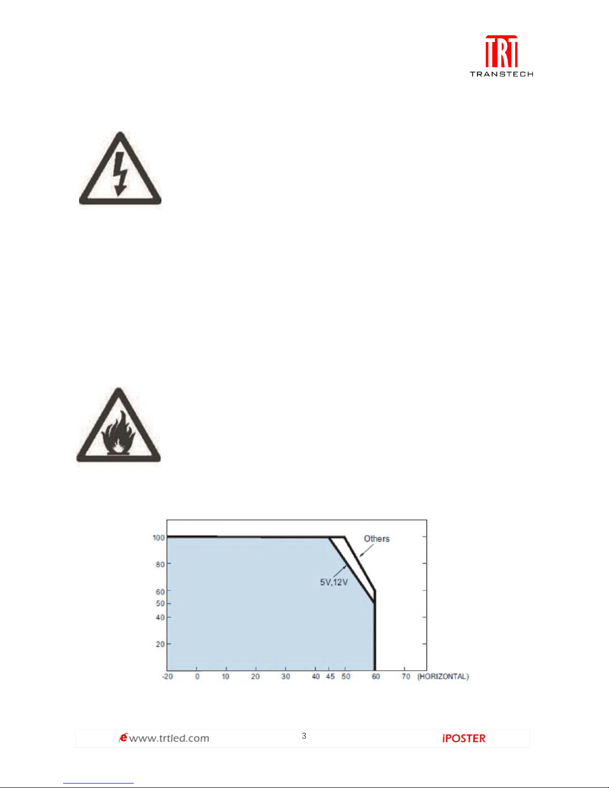
PROTECTION FROM FIRE
Do not stick filters, masks or other material directly onto LED
models.
Do not modify the product in any way not described in this manual.
Install only genuine Radiant parts in or on the product unless an
alternative is described in this manual.
Do not operate the product full load if the ambient temperature of
LOAD (%)
AMBIENT TEMPERATURE(°C)
Page 5
4
Important warnings
Maximum and minimum ambient temperature:
The maximum ambient temperature of iPoster is 50℃; the minimum temperature is
-20℃. The operation humidity is 10—90%RH.
High leakage current:
The combination of power boxes in an installation results in increased levels of
Leakage current.
In order to avoid risk of electric shock due to high leakage current, proper grounding
of the installation is required.
Risk of electric shock/ Risk of fire.
This equipment MUST be earthed:
In order to protect against risk of electric shock, the installation should be properly
grounded.
Defeating the purpose of the grounding type plug will expose you to the risk of
electric shock.
Power system
Main cords:
The power cords delivered with this system have special properties for safety. They
are not user Serviceable. If the power cords are damaged, replace them only with new
ones. Never try to repair a power cord.
PROTECTION FROM INJURY
Created an installation by installing panels at the top and working
downwards. Disassemble an installation by removing panels at the
bottom and working upwards.
Check that all external covers and rigging hardware are securely
fastened.
Block access below the work area and work from a stable platform
whenever installing, servicing or moving the product.
Page 6
5
Data cables:
The data cables provided with this system have special properties for safety. They are
not user serviceable. If the data cables are damaged, replace them only with new ones.
Never try to repair a data cable. Per requirements of the National Electrical Code in
the USA, the length of a data cable must not exceed 100m (332feet). Avoid exposure
of data cables to accidental contact with lightning or power conductors.
IPoster cannot be hot swapped:
Always disconnect the power cord from the control box before connecting or
disconnecting the cable string or one of the iPoster. Any damages caused by
hot-plugging are not included in the repair guarantees of the manufacturer.
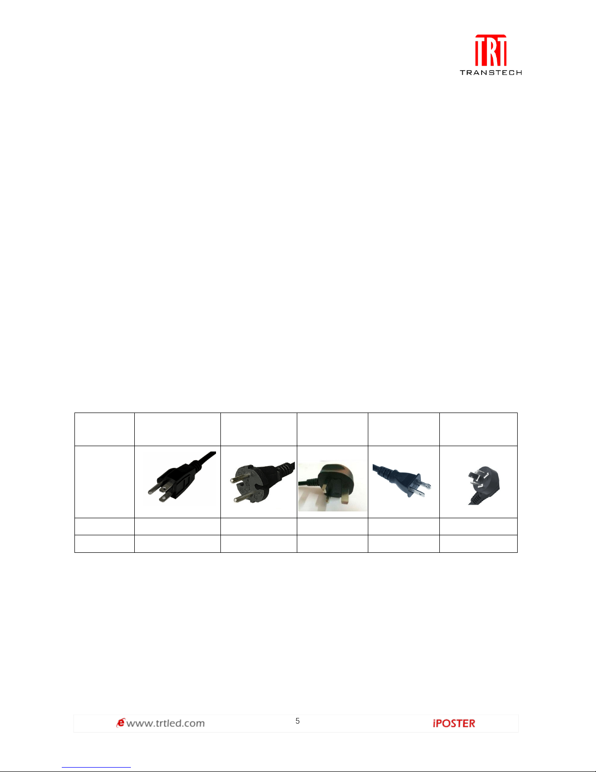
Compatible power cord specifications:
•3-pin
•Rated current: 10A
•By referring to the table below, choose the right plug type and a power cord that is
suitable for your voltage.
Plug type
North American
European
continental
U.K.
Japanese
China
Plug shape
Region
U.S.A./Canada
EU(except U.K.)
U.K.
Japan
China
Voltage
120
230
230
100
220
Safety guidelines
Personal protection
You need to take particular care of suspended loads and wear a safety helmet to avoid
injuries. While assembling heavy objects, take particular care of your hands.
The relevant legal electric requirements of the country, where the system will be
mounted, installed and operated, must be followed as well as the existing regulations
of the operator, such as work, operating and safety regulations.
Page 7

6
Personnel
This installation must be performed by authorized and qualified technical personnel
only. Before the installer begins with the assembly, he must be convinced of the
completeness of the scope of supply including the required accessories. The installer
may only use the prescribed network cables, please see the cabling in this manual.
There must be a security officer who is responsible for the security at diverse tasks
during the installation.
Attention
The installation should be performed only after you are thoroughly familiar with all of
the proper installation instructions and safety checks. This manual contains
fundamental information that should be observed in connection with installation,
start-up, operation and maintenance of the LED video display. If you do not follow
these instructions, it increases the risk of hazards and injury to the user. If you have
any questions during the installation, please contact Transtech LED Co.,Ltd.
Transtech LED Co.,Ltd shall not be liable for personal injury or damage to materials
caused by failure to observe this warning and safety information of this manual.
Furthermore Transtech LED Co.,Ltd cannot be held responsible for damage or injury,
caused by incorrect, inadequate or unsafe use, maintenance or installation of the
entire system. The liability as well as the effects of the same will become void if other
than genuine parts are used.
Before work on the system, the power must be disconnected, and the system must be
checked for absence of power and secured against further connection power.
All repairs of the system may only be carried out by Transtech LED Co.,Ltd respectively
by authorized and qualified technical personnel.
Certification
• CE
• FCC
• ETL
• TUV
• CCC
Page 8
7
iPoster-2.5mm Specification:
Pixel pitch
2.5mm
LED Type
SMD (2020)
LED module size
210×280mm
Module Resolution(H×W)
84×112
LED driving method
1/28 dynamic scan
LED module layout(H×W)
9×2
Cabinet Resolution(H×W)
756×224
Cabinet area
1.09m²
Cabinet size
1902×572×35mm
Ingress Protection
Front IP40/Rear IP40
Power
AC 240/100±10%
Serviceability
Front service & Rear service
Brightness
2000cd/m²
Pixel density/cabinet
169,344
Contrast ratio
3,000:1
Viewing Angle(H/V)
160°/160°
Refresh rate
1920Hz
iPoster-1.9mm Specification:
Pixel pitch
1.9mm
LED Type
SMD (1010)
LED module size
210×280mm
Module Resolution(H×W)
110×146
LED driving method
1/28 dynamic scan
LED module layout(H×W)
9×2
Cabinet Resolution(H×W)
990×292
Cabinet area
1.09m²
Cabinet size
1902×572×35mm
Ingress Protection
Front IP40/Rear IP40
Power
AC 240/100±10%
Serviceability
Front service & Rear service
Brightness
1000cd/m²
Pixel density/cabinet
279,936
Contrast ratio
3,000:1
Viewing Angle(H/V)
160°/160°
Refresh rate
1920Hz
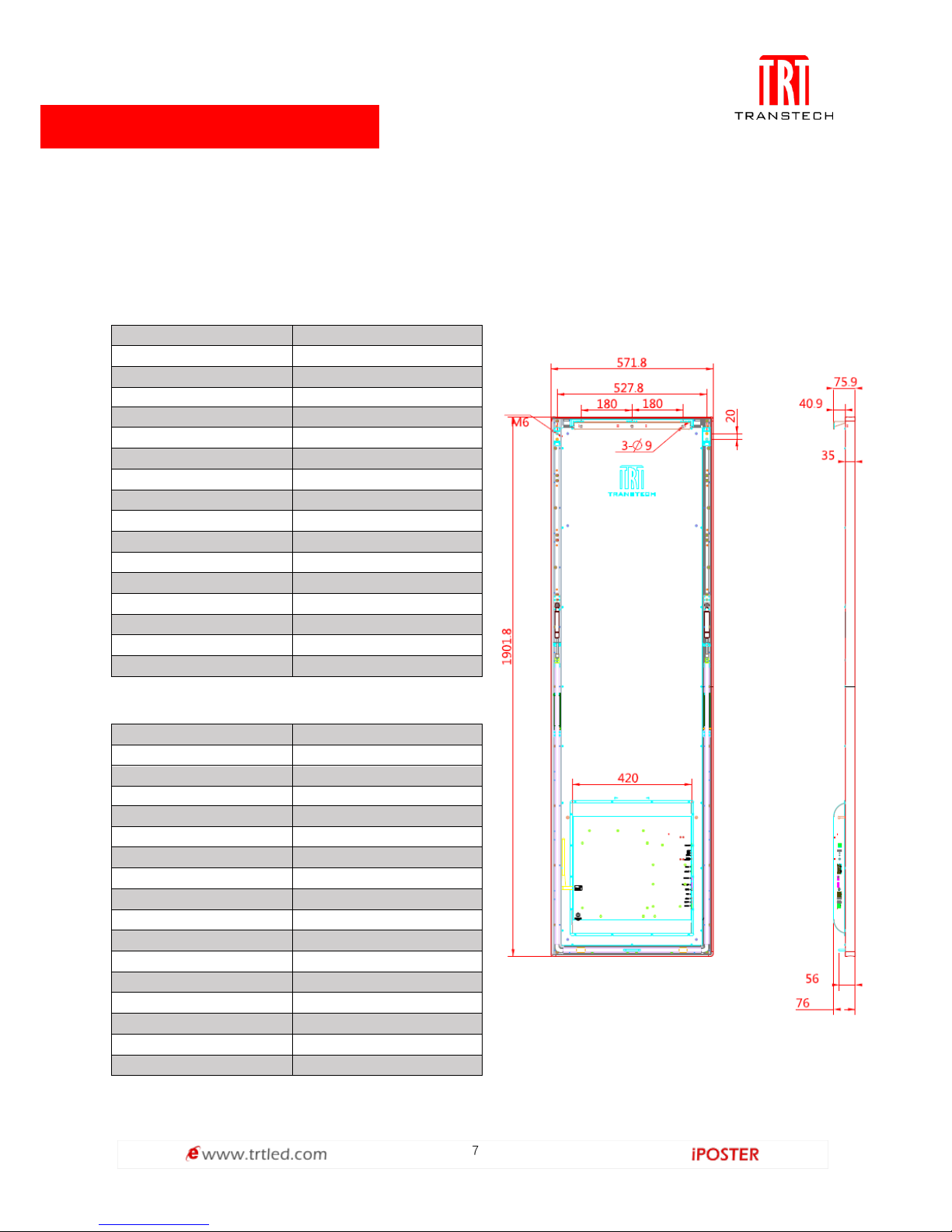
Specification:
Developed by Transtech team alone, iPoster series all new digital poster can be
controlled with fixed or portable Windows, IOS & Android devices. The content can be
refreshed and stored in built-in media player through WIFI or USB to achieve
asynchronous play.
iPoster Dimensions:
Page 9
8
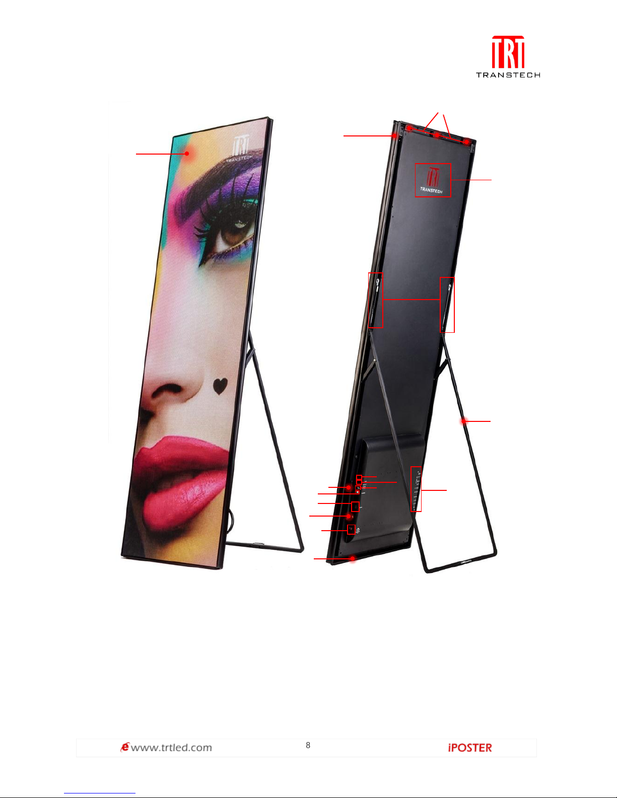
IPoster diagram
Note:
① Display area
② Main frame
③ Hanging accessories installation area
④ LOGO area
⑤ Nitrogen spring
⑥ Stuck
①②③
④
⑤
⑥
⑦
⑧
⑨
⑩
⑪
⑫⑬⑭⑮⑯
⑦ Port area from top: LAN 1, LAN2, HDMI IN, HDMI OUT, AUDIO, LAN, USB1, USB 2, USB 3
⑧ Supporter groove
⑨ Power
⑩ WIFI antenna
⑪ HDMI port
⑫ Cascade port
⑬ Pedestal mounting screw hole
⑭ USB port
⑮ Power indicator,
signal indicator
⑯ Input station
Page 10
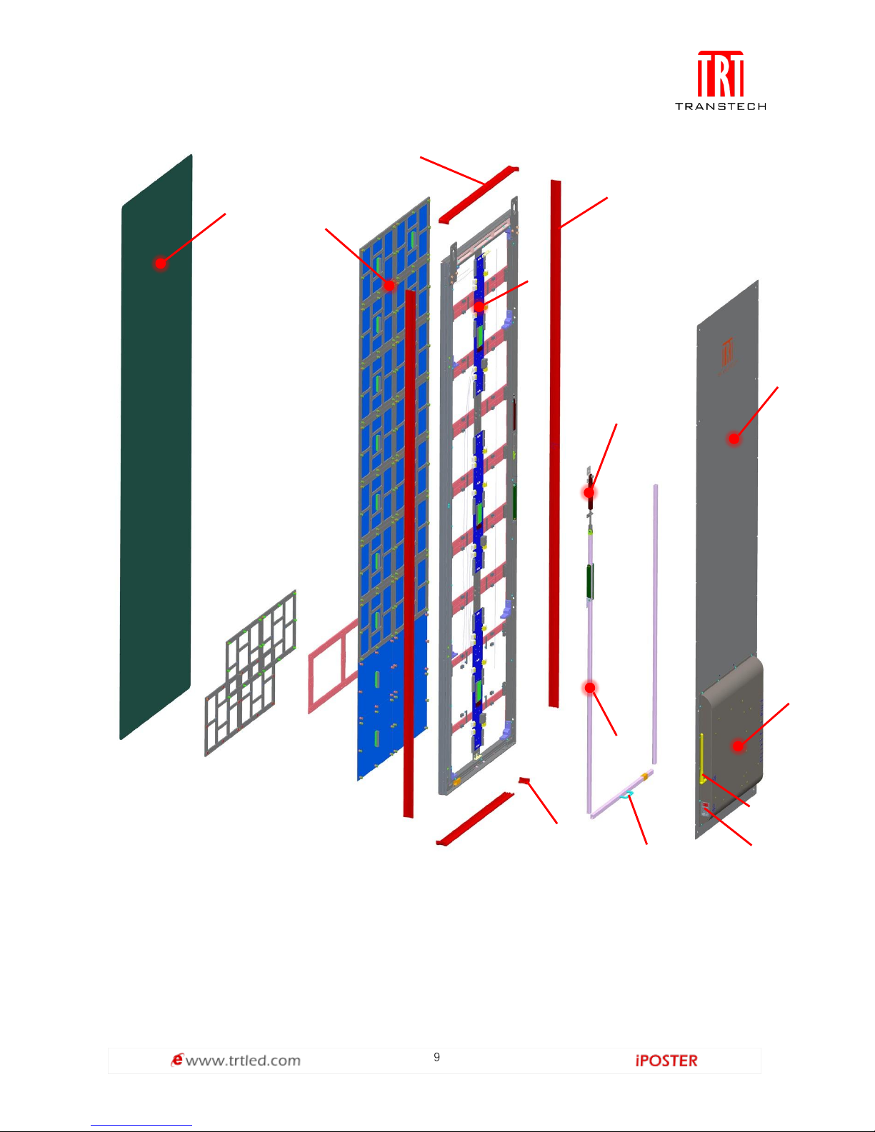
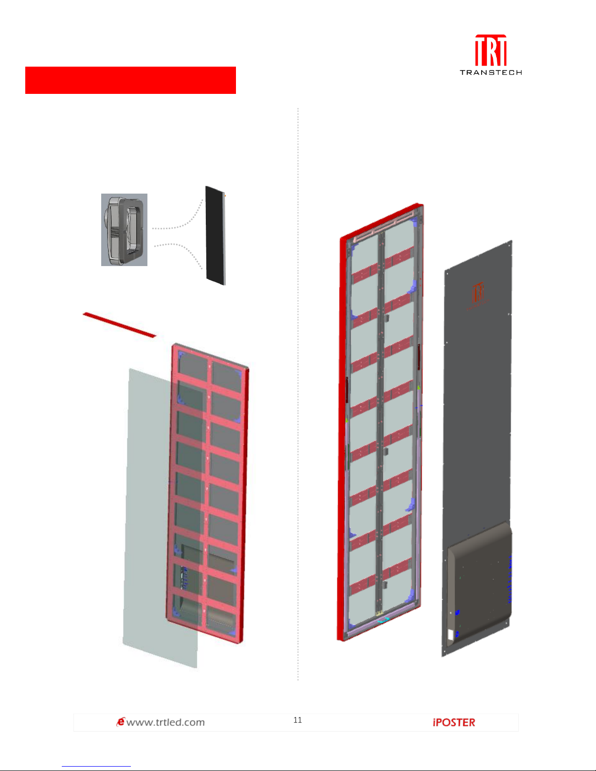
9
Note:
1. Acrylic panel 2. Module & lamp panel 3. Sides frame
4. Top frame 5. HUB board 6. Corner sealer
7. Pneumatic rod 8. Hand-holding 9. Track
10. Backboard 11. Power 12. Antenna
13. Back frame
1 2 3 4 5
6 7 8
9
10
11
12
13
Page 11
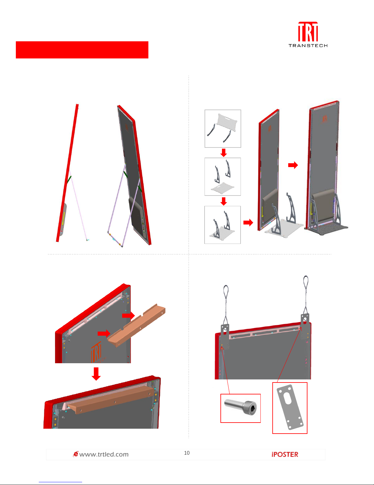
10
Supporter standing
Open the folded supporter to stand
Installation
Pedestal standing
Put the cabinet onto base, fixed with screw
From①to⑤
Wall-mounted
①
②
③
④
⑤
Hanging installation
Page 12
11
Front service
Serviceability:
Rear service
Suck out the module with maintenance tools
Maintenance tools
Module
Move the backboard screws
Page 13
12
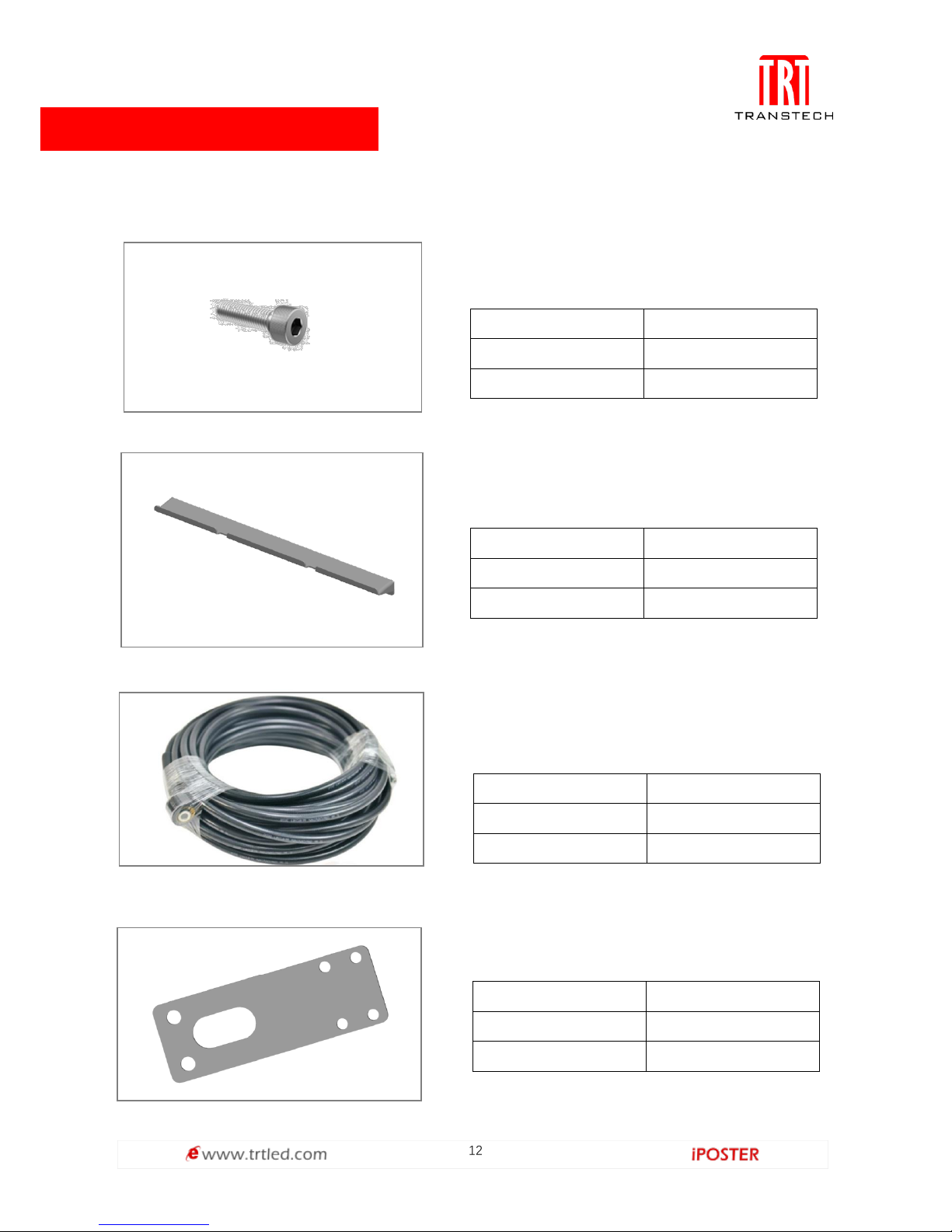
Accessories:
Screws
Connect the base and hanging or wall-mounted
accessories.
Size
M6*25
Quantity
4PCS/set
Material
SUS304
Wall-mounted accessories
Mount iposter on the wall.
Size
410*45.5*27.5mm
Color
Black
Material
SPCC
Power cord ( three core )
Connect the electric closet to screen;
3*2.5m2 wires connects 8-10 cabinets.
Length
20m
Color
Black
Weight
3.5kg
Hanging accessories
Used for hanging iposter.
Size
140*50*3mm
Color
Black
Material
SPCC
Page 14
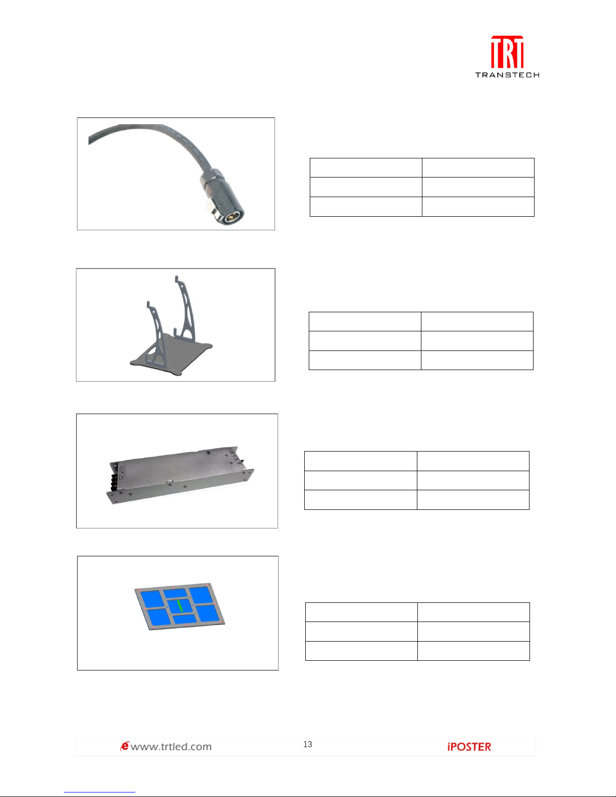
13
Power cord
Connect the power between cabinets.
Length
0.5m
Color
Black
Weight
0.1kg
Base
Adopt stainless steel rope for rigging.
Material
A6063
Color
Black
Size
L571.8*W410mm
Power supply
Mount iposter on pedestal.
Voltage
5V
Color
Silver
Weight
0.66kg
Module
Spare module.
Color
Black
Size
210*280mm
Weight
0.42kg
Page 15
14
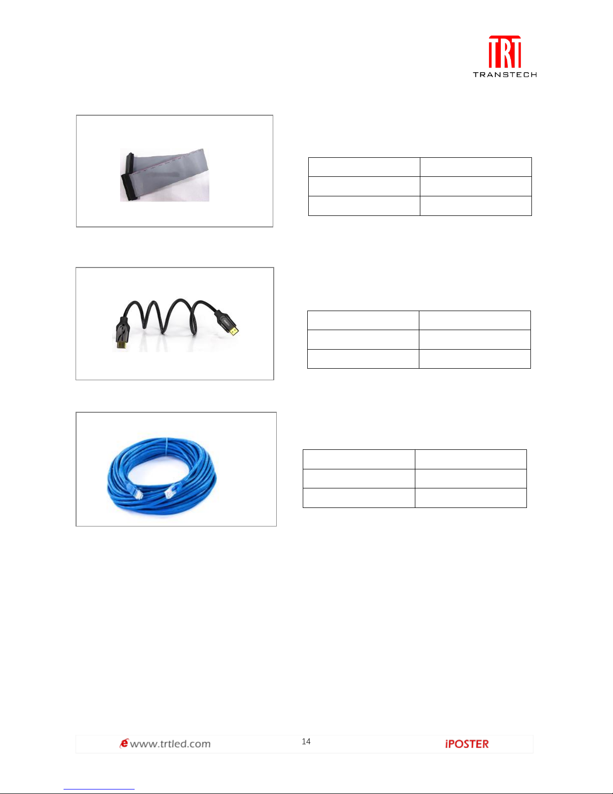
Flat cable
Connect HUB board and module
Length
0.26m
Color
White
Weight
0.1kg
HDMI cable
Sync connect computer
Material
Copper wire
Color
Black
Weight
0.54kg
RJ45 cable
Connect Iposter with LAN or internet
Length
6-8m
Color
Blue
Weight
0.6kg
Page 16
15
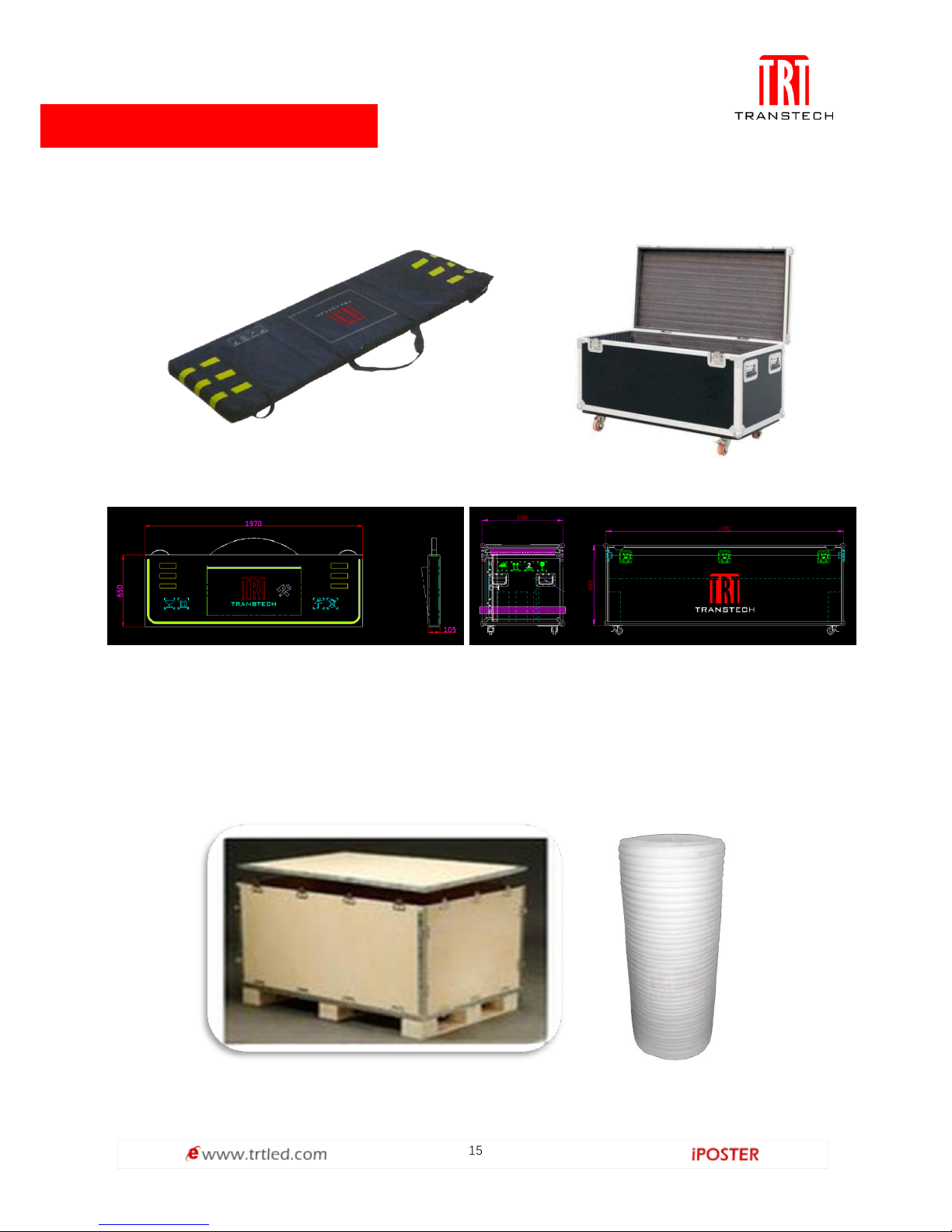
Flight case delivery: 4pcs per case
Wooden case delivery: 4pcs per case
Only suitable for long or short distance of fixed products: Wooden case + Pearl
cotton
Package:
Size:
Page 17
16
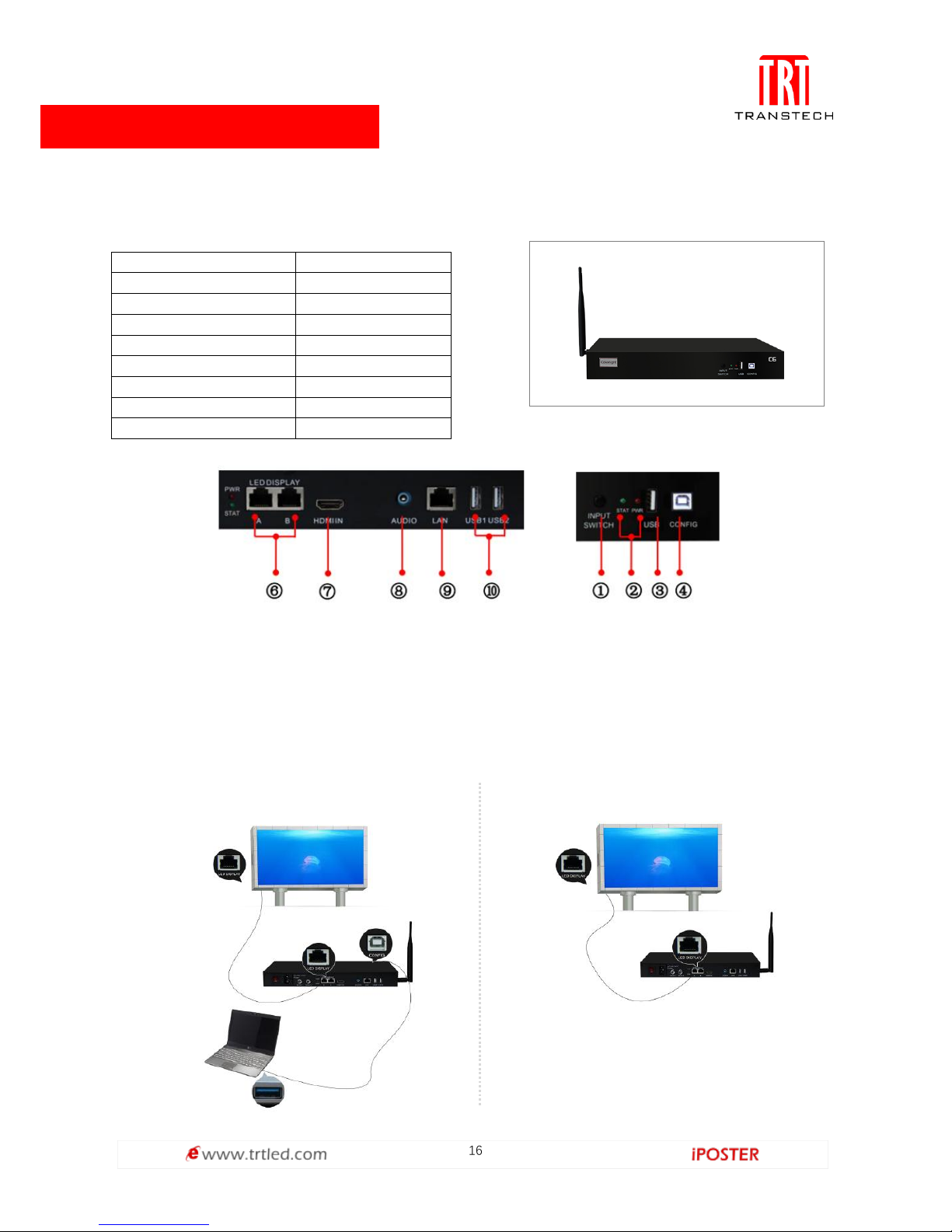
Specification:
Wororking Voltage
100~240VAC
Rated power consumption
10W
Working temperature
-20°C ~ 85°C
Communication port
USB/RJ45
Controlled products
C Series
Data transmission port
1000M Ethemet
Material
SPCC
Dimension
315*205*44mm
Weight
1.5kg
Control system:
IPoster control system is composed by main controller (C6).
Main controller (C)
Note:
①Input Switch ②Indicator Light ③USB Port
④CONFIG ⑥Ethernet port ⑦HDMI input
⑧Audio output ⑨LAN interface ⑩USB
Hardware connection
Control & play without computer
C6 Configuration
Page 18
17
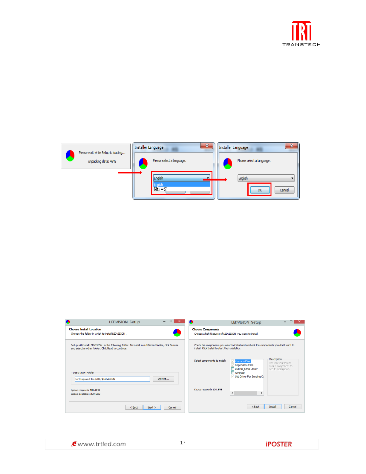
Software installation
First download the installation package of LEDVISION software from Transtech's
official website www.trtled.com, and complete the installation according to the
diagrams shown below.
1. Run the software package, and select [ English ] for installer language. Click [ OK ]
to move on.
Note: Run LEDVISION version 4.20 or higher while using your C6.
2. After selecting a language, an installation wizard like below will appear. Click
[ Next ];
Then choose installation location, click [ Browse ] to change default target location,
then click [ Next ] after completing.
Choose components according to your own computer status, click [ Install ] to
complete.
After the installation is complete you are ready to use LEDVISION.
Page 19
18
C6 Parameter Settings
Connection Settings
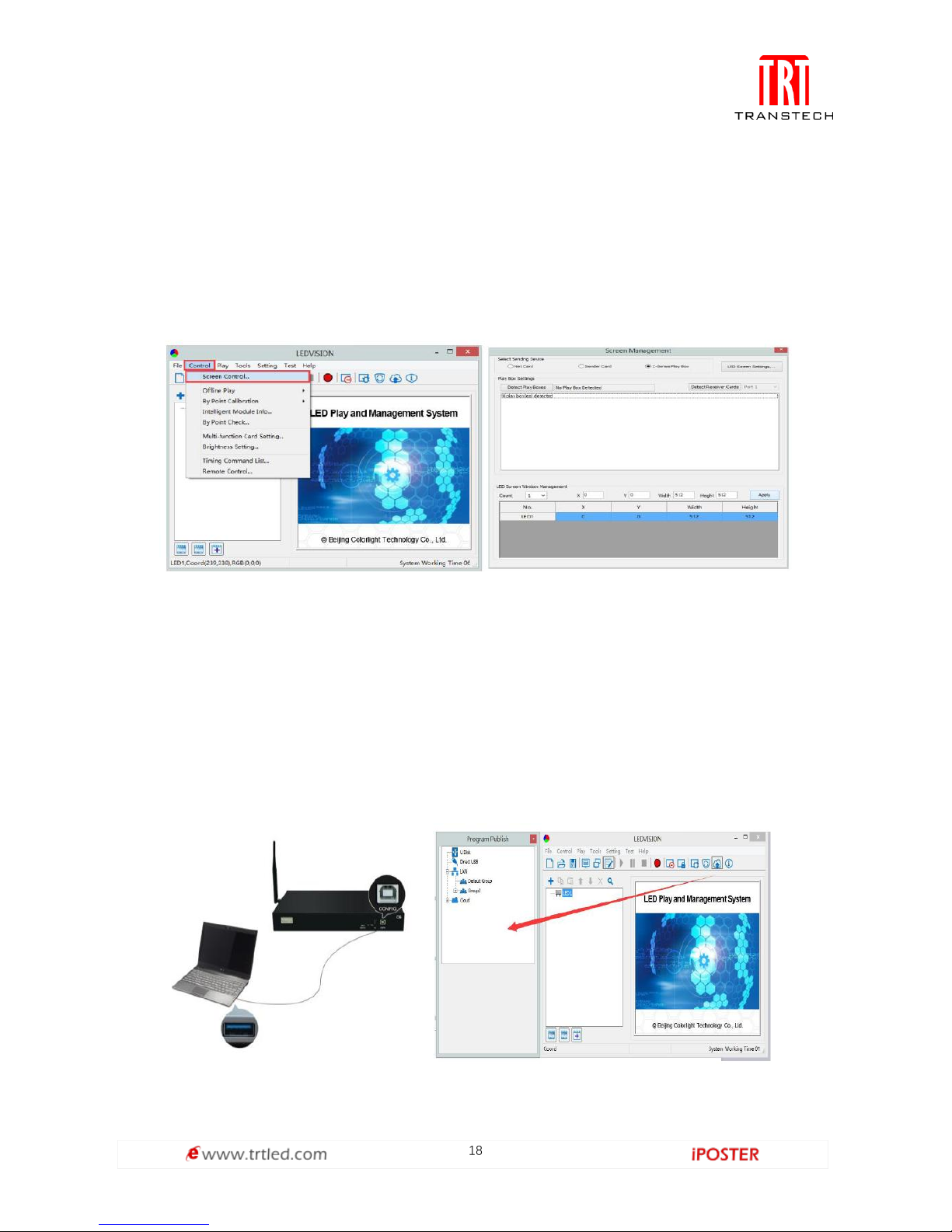
1. Before connecting your C6 to the computer, first click the control menu [ Control ]
→ [ Screen Control ], then select [ C-Series Play Box ] in Select Sending Device, then
set up [ LED Screen Window Management ].
Note: If you do not complete this step, LEDVISION may not function properly because
of a conflict between Net Card mode and C6 config interface.
2. Use standard USB A/B cable to connect C6 to computer when C6 is powered on,
one side to connect USB port, another side for C6 config port.
Click [ Publish Program to C Series Playboxes ] (as shown in the red box) to enter
program publish interface.
Page 20
19
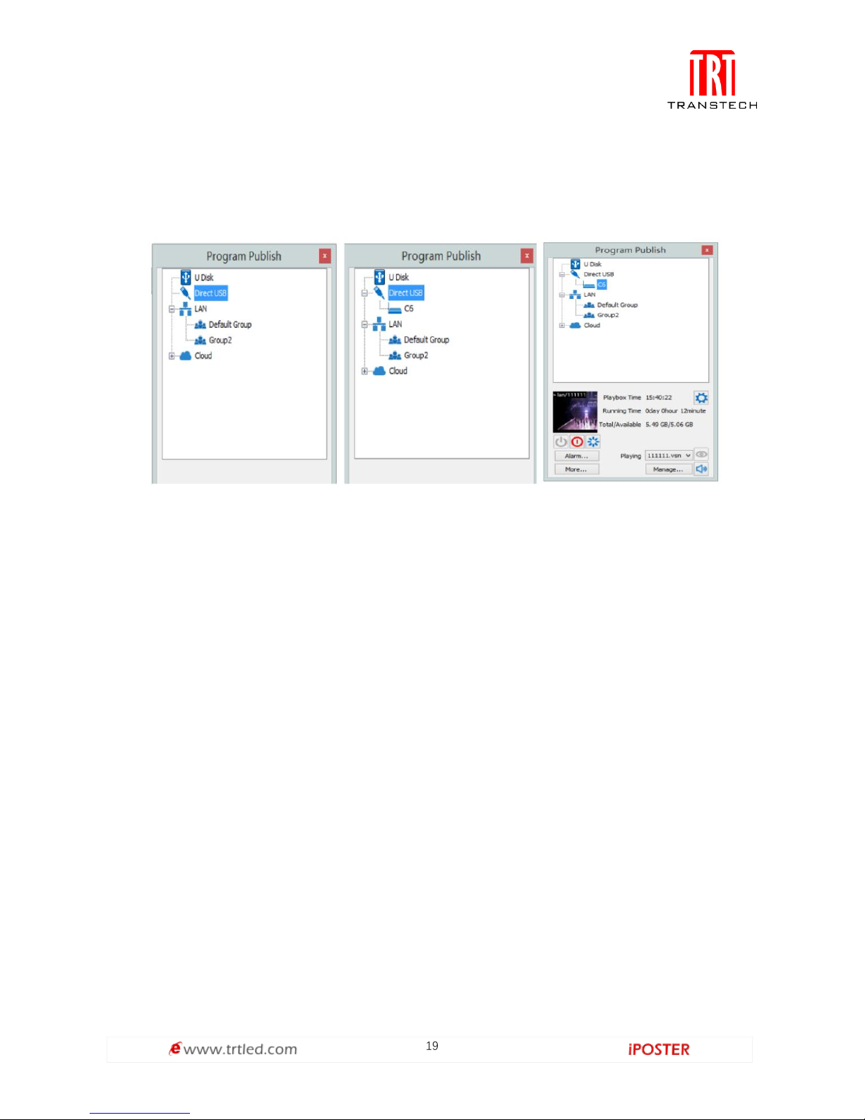
3. Left-click [ Direct USB ] and then right-click choose [ Refresh ], your C6 will show up
in program publishing window, select your device to set parameters and choose what
content to play.
Basic settings
● Ensure LED display is under normal configuration before setting on C6 parameters.
● When setting up C6 parameters, you can connect your C6 to your PC through a
standard USB A/B cable, and connect your C6 to your LED screen through network
cable.
1. Play Box Date and Time: Click [ Modify ] to set up date and time, or time zone as
well.
2. Alarm Settings: Set wake up and sleeping time, which works once checked.
3. Play box Time: Display the setting time.
Running Time: Calculated once C6 sender powered on.
Capacity/Remain: View memory utilization.
4. Power on, Sleep, Restart: To perform C6 sender box operation like power on, sleep
and restart once clicked.
5. Playing: Use the drop down menu to play programs.
Program Management: Check, delete and choose program, and much more.
Page 21

20
The surface development of your C6’s parameter setting interface is shown below:
Advanced settings
1. Playing parameters
The [ width ]/ [ Height ] you input must be equal
to or slightly larger than he actual screen
resolution.
② Output
Every Frame ( Default ).
Every Other Frame ( Choosing [ every other
frame ] can help avoid lag
when image loading area is too large ).
③ Control Area
Select [ Custom ] in control area, and modify the
values according to your network interface
control area, click [ Apply ] to complete setting.
Page 22

21
2. Network settings
① WiFi
Check [ WiFi ] in network tab, and input your WiFi login information for [ network
name ] and [ password ], then click [ Apply ] and [ Refresh ] to complete setting, click
[ detail... ] to check connection status.
② WiFi Hotspot
Input your [ network name ] and [ password ] to use a WiFi Hotspot.
CDMA: 2.4G or 5G (5G mode will be faster and more reliable if both smart phone and
computer support 5G WiFi.)
Channel: 14 choices, to avoid network overload.
Page 23

22
③ LAN (Network Cable)
A. Automatically Obtain an IP Address (Default)
When you connect your C6’s LAN port to a networked router, your C6 will
automatically obtain an IP address.
B. Use the Following IP Address
To use a specific IP address, enter
information for [ IP ], [ Subnet
Mask ] and [ Gateway ], then
connect C6 LAN port to the router.
C. Details
View network connection
information like connection
status, Mac Address, IP, and
Subnet Mask.
C6 Async Content Editing and Sync Playing
Async Content Editing
When you open LEDVISION, you will see [ LED1 ] in program editing area. Right-click
[ LED1 ] to add [ normal page ], you can add [ file window ] in [ normal page ], then
add [ image ] and [ video ] under the [ file window ] to add media for asynchronous
play.
Page 24

23
Async Content Publishing
1. Publish Contents through Direct USB
① In [ program editing area ], after finishing content editing, select the [ program
page ] that you are going to publish;
② Click [ C6 ] and then right-click to choose [ Publish Program to current playbox ],
you must rename the content and allow it to finish uploading to fully publish your
program.
Page 25

24
2. Content Publishing through USB disk
To begin publishing through USB, first insert your USB stick to the PC USB port.
Click [ Publish Program to C Series Playboxes ] (as shown in the red box) to extend
program publishing window.
Note: USB stick should be empty before publishing for best performance. Remove
previous update contents before using it to update or play new contents, so as to
avoid any problems.
Auto identify USB stick when set up USB stick parameters, click [ U Disk ] to
choose [ Your USB’s Drive].
①Select [ program page ] in program editing area.
②Choose USB Stick Mode:
● Play program from USB stick ( Auto play USB stick contents after inserting to C6;
and the content be stored in C6).
● Upload program from USB stick ( Auto play USB stick content after inserting to C6;
the content will be stored in C6).
Page 26

25
③Select the drive letter under USB stick group, and then right-click to choose
[ Publish the current program to the selected disk ], after publishing program
successfully, insert USB stick into C6 USB port.
Note: A rotating circle in LED upper left corner will appear during the upload
procedure. You may unplug the USB drive after the circle disappears.
Sync Playing
In sync play, your C6 plays contents sent to its HDMI port by an external source like
your PC.
Note: C6 will automatically switch to play sync signal content when an external HDMI
signal input is detected. You can press [ INPUT SWITCH ] button to return async signal
content playing.
Page 27

26
Network Management of C6
Connection and Management
1. LAN Connection: Connect C6 to
network through WiFi or LAN port.
2. C6 network management: After
controlled end ( PC, smart phone, or
other device) and C6 are connected
into same LAN, select [ LAN ] then
[ Refresh ]. LEDVISION will auto
identify C6, which will have already
connected to same network and
place C6 into Default Group. You
can manage your C6 under Default
Group.
Add Group and C6
1. Add Group: Select [ LAN ], and right-click to choose [ Add Group ].
2. Add C6 Device: Select any playbox group, and right-click to choose [ Manually Add
Playbox ], then input C6’s corresponding IP (Add even if your device did not connect
to network).
Page 28

27
Cloud operation
Internet ID Application
Firstly, you need apply an Internet ID to login our server, and the ID is not open for
everyone to register, the application to our company is necessary.
Internet ID Login
You can login our server(URL:https://colorlightcloud.com) to manage terminal
equipment while you have an Internet ID. As shown in Figure 1.2-1 below, you need to
input your account and password.
Figure 1.2-1
You will see as shown in Figure 1.2-2 after successful login. The menu is on the left,
which contains items such as equipment management, media management, program
management, etc.; the window for operating is on the right.
Figure 1.2-2
Page 29

28
Equipment Management
1. New/Edit/Delete Terminal Group
On the home page, click Terminal-->Select Group, and click to enter the page for
adding a new terminal group (Figure 1.3.1-1). As shown in Figure 1.3.1-2, fill in the
information and click Submit, a new terminal group is built.
Figure 1.3.1-1
Figure 1.3.1-2
Page 30

29
Click , and you can re-edit the information of terminal group, the interface is
shown in Figure 1.3.1-3 (Note: You cannot re-edited initial terminal group, only the
child terminal group can be re-edited).
Figure 1.3.1-3
Click , and you can delete selected terminal group and terminals under it, as
shown in Figure 1.3.1-4 (Note: Initial terminal group cannot be deleted).
Figure 1.3.1-4
Page 31

30
2. New/Edit/Delete Terminal
As shown in Figure 1.3.2-1, you can add a new terminal. Click New as shown in Figure
1.3.2-2, fill in the information and click Submit to complete (Note: Please write down
the terminal account, as it’s the LED player account in the server, which should later
be used to setup the LED player).
Figure 1.3.2-1
Figure 1.3.2-2
Page 32

31
After filling in the information and submitting, we can see the existing terminal under
corresponding terminal group. The new terminal is gray, which means it’s not online
at the moment as shown in Figure 1.3.2-3.
Figure 1.3.2-3
The operation of deleting terminal is in Edit, click and you can not only edit
the information of terminal, but select Delete in the bottom-left corner to delete the
terminal, as shown in Figure 1.3.2-4.
Figure 1.3.2-4
Page 33

32
3. Terminal Connection with Internet
The C6 can be connected to Internet by WIFI, 3/4G, and network cable. In order to
connect with the server, you should:
A. Connect the computer via USB cable provided,
B. Start LEDVISION,
C. Click "Publish program to C6 player",
D. Refresh and find the player currently connected via the USB Cable,
E. Click the player to select it,
F. Click the "More..." button on the bottom panel,
Page 34

33
G. Enter Password: 168,
H. Select the "Led" tab in the "Advanced Settings" window,
I. Connection status could be found in the Internet section as shown in Figure 1.3.3-1.
Please check the figure below for the Username, Password and URL. After filling in
corresponding information, click Apply. The "Login Succeed" message shows that
it’s online in the server.
Figure 1.3.3-1
Page 35

34
4. Terminal Management
After setting up the terminal, login the server in the browser for checking its online status. The
green frame means that the device is online as shown in Figure 1.3.4-1 below.
1. Finish the initialization by click the device, and take a screenshot.
2. Terminal Operations:
Click to reboot the equipment,
Figure 1.3.4-1
Click if you want to switch the program, and the interface is shown in
Figure 1.3.4-2, you can click to switch the program, click to delete
the program, click to delete all programs in the terminal, click
to clear all useless Internet cached resources.
Moreover, you can remotely control device's brightness, color temperature, volume
and switch between sync and async signals.
Page 36

35
Figure 1.3.4-2
You can click for instantly checking out what is displayed on the LED
screen for the moment, as shown in Figure 1.3.4-3; Click to publish a
program of single line text, as shown in Figure 1.3.4-4.
Figure 1.3.4-3
Page 37

36
Figure 1.3.4-4
5. Terminal Package Updated
Click Advanced Settings, select Terminal being updated, the interface is shown in Figure 1.3.5-1,
and click , select right upgrade package to start upgrade.
Figure 1.3.5-1
Page 38

37
Media Management
1. Media Upload
To upload media which users need to the server, click Media Management->File
Upload as shown in Figure 1.4.1-1. Click Select File, find the media, click Open to
complete; or drag the media in the dotted box directly. (PS: Capacity of single media
is limited to 512M Bytes)
Figure 1.4.1-1
2. Media List
Media list can only display media uploaded to the server by users, including videos
and pictures; and users can delete useless media in Media List. If media has been used,
users must delete programs that occupy it and then delete media (The mouse is
moved over occupied media and it will remind us that the media has been occupied
by certain programs), as shown in Figure 1.4.2-1. (PS: Media List can also display
media in programs being uploaded from C/S port)
Figure 1.4.2-1
Page 39

38
Program Management
1. Program List
Program Management is shown in Figure 1.5.1-1. It displays all programs of Internet
created by this account, also including programs sent from C/S.
Figure 1.5.1-1
You can click to build a new program, click to edit the program (for
being created from B/S only), click to delete the program uploaded to server
by the account.
2. New Program
Build a new program of Internet. Click Edit Program, as shown in Figure 1.5.2-1. Click
to add Program Page and File Window (It supports the program of several
program pages and several file windows, File Window supports 4 file windows in
maximum), click to adjust the play order, click to delete program page,
file window or media; program name can be filled in arbitrarily, height and width are
set according to the size of screen with Terminal; preview window and adjustment of
size of file window are on the right; click to upload the program to server
Page 40

39
after building it, and it can be allotted freely or re-edited.
Figure 1.5.2-1
3. Program Allocation
Program can be clicked in the program list after building programs, as shown in
Figure 1.5.3-1, click , as shown in Figure 1.5.3-2, you can select terminal
group to send the program to all terminals of it; click , and you can see
all materials of the program (videos and pictures only); click , and you can
see download status of every terminal as shown in Figure 1.5.3-3, of course, you can
see the download status in advanced settings as shown in Figure 1.5.3-4.
Figure 1.5.3-1
Page 41

40
Figure 1.5.3-2
Figure 1.5.3-3
Figure 1.5.3-4
Page 42

41
Security Monitoring
When unknown users attack server maliciously, or account and password input error
exceed 6 times, the server will lock corresponding IP of the user, the user also can
unlock it. As shown in Figure 1.6-1, all blocked users on the server can be recorded.
Figure 1.6-1
Command Schedule
Command Schedule locates under Terminal Management, it’s necessary to select a
terminal group for setting schedule, as shown in Figure 1.7-1.
Click , as shown in Figure 1.7-2, users can command Type, Execution Time,
Valid Date, Valid Week and etc. Click to enforce the schedule set by users.
Figure 1.7-1
Page 43

42
Figure 1.7-2
Language Switch
Switching language is on the left toolbar, as shown in Figure 1.8-1. Click Account Info-->Personal
Setting-->Language to switch Simplified Chinese, Traditional Chinese or English.
Figure 1.8-1
Account Management
The module applies to multi-users management, register new user and bind
corresponding terminal group, there are two permission assignments: administrator
and program maker (Only administrator can register new users). All subsidiary
accounts under the certain account are shown in Figure 1.9-1, new account
registration is shown in Figure 1.9-2.
Page 44

43
Figure 1.9-1
Figure 1.9-2
C/S settings
Connection with Server
Start LEDVISION and enter operation interface of C series products, as shown in
Figure 2.1-1, click Cloud, enter username and URL, click Login and you can see all
terminal groups and terminals of this account.(URL:https://smart.lednets.com/clt/)
Page 45

44
Figure 2.1-1
Add/Delete Terminal (New LEDVISION Function)
Drag terminal in related terminal group by LEDVISION directly, as shown in Figure
2.2-1. It’s OK to connect with USB or LAN.
Figure 2.2-1
Page 46

45
Select deleted terminal and right click to delete, as shown in Figure 2.2-2.
Figure 2.2-2
Connection with Server
1. Program Editing and Publishing
Program is edited by LEDVISION (Please look up related document and help of
LEDVISION), program publishing is same as the way of LEDVISION by USB or LAN,
right-click terminal group or terminal and select Publish, also, you can drag program
in the terminal group or terminal to complete, the progress window of uploading and
downloading will pop up, as shown in Figure 2.3.1-1.
Figure 2.3.1-1
Page 47

46
2. Terminal Management
Click the terminal, as shown in Figure 2.3.2-1, and you can see the terminal
information, like version, running time and etc. Click , they are Power on,
Sleep and Restart; click to conduct program management, like
program switch and delete.
Figure 2.3.2-1
C-Cloud Chrome Plugins Setup and User Instruction
Setup
1. Click Account Info and select Download Chrome APP after entering the web, as
shown in Figure 3.1-1 below.
Figure 3.1-1
Page 48

47
2. After downloading, select More Tools-->Expanded Program (Figure 3.1-2), drag downloaded
Chrome extension (CRX) in the interface and add, at the moment, as shown in Figure 3.1-3, select
Detailed Information-->Create a Shortcut on the desktop.
Figure 3.1-2
Figure 3.1-3
Page 49

48
User Instruction
1. Click the desktop or Chrome extension to start C-CLOUD, as shown in Figure 3.2-1.
Figure 3.2-1
Fill in the server name and URL, select Add, as shown in Figure 3.2-2, click Enter, it’s
same as the login interface of entering browser. After the first login, user can enter
directly without inputting username and password again; click bottom-left corner to
return and users can switch the username.
Figure 3.2-2
Page 50

49
IOS app operation
This function requires Colorlight LED Player >= 1.32 and,
iOS "LED Assistant" version >= 2.7.8. Please download the latest Colorlight "LED
Assistant" by scanning code below:
Power on the iposter before entering software operation. Open the WLAN interface
of phone and connect the wife whose username is on the backboard and the
password is 12345678. After connecting, you can follow the steps to operate.
Page 51

50
1. Connect to Colorlight LED Player
Page 52

51
2. Find and Select Target Colorlight LED Player
Page 53

52
3. Create a New Program
Page 54

53
4. Edit the Default Region
Page 55

54
5. Make the Region "Carousel" Region Type
Page 56

55
6. Add PNG (Support Transparent) or JPG Logo
Page 57

56
7. Select Picture
Page 58

57
8. Type in Text
Page 59

58
9. "Back" to Program Edit UI
Page 60

59
10. Upload "Carousel" Program to LEDPlayer
Page 61

60
11. Any Program Name Will Do
Page 62

61
12. Check the Screenshot from LED
Page 63

62
13. Even Check the Full Screenshot
Page 64

63
Routine maintenance:
1.Regular use. After put into use, 25-30 hours and 5 times usage per month is
necessary to keep the display dry and deliver a stable performance.
2.Regular clean. Normally one time every half of a year is OK. Cut off the electricity
power, and then use a dry brush to sweep from top to the bottom. Then use a tide wet
rag to wipe one more time. After the cleaning, the LED display should put through
electricity at least 4 hours to keep it dry.
3.Power system maintenance. Dairy check on power supply system. Routine
cleaning inside the power distribution cabinet and fasten screws connections one
time per month. Electrician certificate is needed for the maintenance stuff. Hot plug is
forbidden.
Repair: common failures and trouble shooting
Common failures
Trouble shooting
Black screen
1.Ensure the power is turning on or not.
2.Check communication circuits are connected right.
3.Check the communication green light of sending
card & receiving card is flashing or not.
4.Check the screen saver is on or not; check the
screen is black, blue or normal.
Module not working
1.Check if +5V or GND is operating. •
2.Check if +5V or GND is short circuit.
3.Check if the signal is normal.
Part of module malfunction
1.Check that the golden pin of the module is in
contact, elasticity is good, Off-pad or not.
2.Check the module pad or golden pin for impurities,
debris, etc.
Maintenance & Repair:
Page 65

THE END
4th Floor, Block12C, Jugao Technology Park, Tianliao
Community, Gongming Town, Guangming District,
Shenzhen, China.
Phone: +86 (755)27150399
E-mail: info@trtled.com
 Loading...