

Page 1

TRANSPOCKET 1400
Primärgetakteter
Schweißgleichrichter
BEDIENUNGSANLEITUNG
ERSATZTEILLISTE
Primary transistor-switched
welding rectifier
OPERATING
INSTRUCTIONS
SPARE PARTS
LIST
Redresseur de soudage
à hacheur primaire
MODE
D’EMPLOI
LISTE DE PIECES
DE RECHANGE
42,0410,0475 012000
Page 2

Page 3

SEHR GEEHRTER FRONIUS-KUNDE
Die vorliegende Bedienungsanleitung soll Sie mit Bedienung und Wartung der TransPocket 1400 (TP 1400) vertraut machen. Es liegt in Ihrem
Interesse, die Bedienungsanleitung aufmerksam zu lesen, und die hier
angegebenen Weisungen gewissenhaft zu befolgen. Sie vermeiden dadurch
Störungen durch Bedienungsfehler. Das Gerät wird Ihnen dies durch stete
Einsatzbereitschaft und lange Lebensdauer lohnen.
FRONIUS SCHWEISSMASCHINEN
VERTRIEB GMBH & COKG
Achtung! Die Inbetriebnahme des Gerätes darf nur durch geschultes
Personal und nur im Rahmen der technischen Bestimmungen erfolgen. Vor Inbetriebnahme unbedingt das Kapitel "Sicherheitsvorschriften" lesen.
DEUTSCH
INHALTSVERZEICHNIS
Sehr geehrter Fronius-Kunde ..................................................................... 3
Sicherheitsvorschriften ............................................................................... 4
Allgemeines ............................................................................................ 4
Bestimmungsgemässe Verwendung ...................................................... 4
Verpflichtungen des Betreibers .............................................................. 4
Verpflichtungen des Personals ............................................................... 4
Persönliche Schutzausrüstung .............................................................. 4
Gefahr durch schädliche Gase und Dämpfe ......................................... 4
Gefahr durch Funkenflug ........................................................................ 4
Gefahren durch Netz- und Schweiss-strom .......................................... 4
Besondere Gefahrenstellen .................................................................... 4
Informelle Sicherheitsmassnahmen ....................................................... 5
Sicherheitsmassnahmen am Aufstellort ................................................. 5
Sicherheitsmassnahmen im Normalbetrieb ........................................... 5
Sicherheitstechnische Inspektion ........................................................... 5
Veränderungen am Schweissgerät ........................................................ 5
Ersatz- und Verschleissteile .................................................................. 5
Kalibrieren von Schweissgeräten .......................................................... 5
Die CE-Kennzeichnung ......................................................................... 5
Urheberrecht ........................................................................................... 5
Allgemeines ................................................................................................ 6
Prinzip..................................................................................................... 6
Gerätekonzept ........................................................................................ 6
Einsatzgebiete ........................................................................................ 6
Beschreibung der Bedienelemente ............................................................ 6
Schweissgerät in Betrieb nehmen ............................................................. 7
Bestimmungsgemässe Verwendung ...................................................... 7
Aufstellbestimmungen ............................................................................. 7
Netzanschluss ........................................................................................ 7
Netzstecker anschliessen ...................................................................... 7
E-Handschweissen .................................................................................... 7
WIG-Schweissen ....................................................................................... 7
Pflege und Wartung .................................................................................... 8
Technische Daten ....................................................................................... 8
Fehlerdiagnose und -behebung .................................................................. 9
Ersatzteilliste
Schaltplan
Fronius - Vertriebs- und Service-Niederlassungen
3
Page 4

SICHERHEITSVORSCHRIFTEN
ALLGEMEINES
Das Schweißgerät ist nach dem Stand der Technik und den anerkannten
sicherheitstechnischen Regeln gefertigt. Dennoch drohen bei Fehlbedienung oder Mißbrauch Gefahr für
- Leib und Leben des Bedieners oder Dritten,
- das Schweißgerät und andere Sachwerte des Betreibers,
- die effiziente Arbeit mit dem Schweißgerät.
Alle Personen, die mit der Inbetriebnahme, Bedienung, Wartung und
Instandhaltung des Schweißgerätes zu tun haben, müssen
- entsprechend qualifiziert sein,
- Kenntnisse vom Schweißen haben und
- diese Bedienungsanleitung genau beachten.
Störungen, die die Sicherheit beeinträchtigen können, sind umgehend
zu beseitigen.
Es geht um Ihre Sicherheit!
BESTIMMUNGSGEMÄSSE VERWENDUNG
Das Schweißgerät ist ausschließlich für Arbeiten im Sinne der bestimmungsgemäßen Verwendung (siehe Kapitel "Schweißgerät in Betrieb
nehmen") zu benutzen.
Zur bestimmungsgemäßen Verwendung gehört auch
- das Beachten aller Hinweise aus der Bedienungsanleitung
- die Einhaltung der Inspektions- und Wartungsarbeiten
VERPFLICHTUNGEN DES BETREIBERS
Der Betreiber verpflichtet sich, nur Personen am Schweißgerät arbeiten
zu lassen, die
- mit den grundlegenden Vorschriften über Arbeitssicherheit und Unfallverhütung vertraut und in die Handhabung des Schweißgerätes
eingewiesen sind
- das Sicherheitskapitel und die Warnhinweise in dieser Bedienungsanleitung gelesen, verstanden und durch ihre Unterschrift bestätigt
haben
Das sicherheitsbewußte Arbeiten des Personals ist in regelmäßigen
Abständen zu überprüfen.
Befinden sich Personen in der Nähe so müssen
- diese über die Gefahren unterrichtet,
- Schutzmittel zur Verfügung gestellt bzw.
- Schutzwände bzw. -Vorhänge aufgebaut werden.
GEFAHR DURCH SCHÄDLICHE GASE UND DÄMPFE
- Entstehenden Rauch sowie schädliche Gase durch geeignete Mittel
aus dem Arbeitsbereich absaugen.
- Für ausreichende Frischluftzufuhr sorgen.
- Lösungsmitteldämpfe vom Strahlungsbereich des Lichtbogens fernhalten.
GEFAHR DURCH FUNKENFLUG
- Brennbare Gegenstände aus dem Arbeitsbereich entfernen.
- An Behältern in denen Gase, Treibstoffe, Mineralöle und dgl. gelagert
sind/waren, darf nicht geschweißt werden. Durch Rückstände besteht Explosionsgefahr.
- In feuer- u. explosionsgefährdeten Räumen gelten besondere Vorschriften - entsprechende nationale und internationale Bestimmungen beachten.
GEFAHREN DURCH NETZ- UND SCHWEISS-STROM
- Ein Elektroschock kann tödlich sein. Jeder Elektroschock ist grundsätzlich lebensgefährlich.
- Durch hohe Stromstärke erzeugte magnetische Felder können die
Funktion lebenswichtiger elektronischer Geräte (z.B. Herzschrittmacher) beeinträchtigen. Träger solcher Geräte, sollten sich durch ihren
Arzt beraten lassen, bevor sie sich in unmittelbarer Nähe des Schweißarbeitsplatzes aufhalten.
- Sämtliche Schweißkabel müssen fest, unbeschädigt und isoliert sein.
Lose Verbindungen und angeschmorte Kabel sofort erneuern.
- Netz- u. Gerätezuleitung regelmäßig von einer Elektro-Fachkraft auf
Funktionstüchtigkeit des Schutzleiters überprüfen lassen.
- Vor Öffnen des Schweißgerätes sicherstellen, daß dieses stromlos
ist. Bauteile die elektrische Ladung speichern entladen.
- Sind Arbeiten an spannungsführenden Teilen notwendig, ist eine
zweite Person hinzuzuziehen, die notfalls den Hauptschalter ausschaltet.
VERPFLICHTUNGEN DES PERSONALS
Alle Personen, die mit Arbeiten am Schweißgerät beauftragt sind, verpflichten sich, vor Arbeitsbeginn
- die grundlegenden Vorschriften über Arbeitssicherheit und Unfallverhütung zu beachten
- das Sicherheitskapitel und die Warnhinweise in dieser Bedienungsanleitung zu lesen und durch ihre Unterschrift zu bestätigen, daß sie
diese verstanden haben
PERSÖNLICHE SCHUTZAUSRÜSTUNG
Treffen Sie für Ihre persönliche Sicherheit folgende Vorkehrungen:
- Festes, auch bei Nässe, isolierendes Schuhwerk tragen
- Hände durch isolierende Handschuhe schützen
- Augen durch Schutzschild mit vorschriftsmäßigem Filtereinsatz vor
UV-Strahlen schützen
- Nur geeignete (schwer entflammbare) Kleidungsstücke verwenden
- Bei erhöhter Lärmbelastung Gehörschutz verwenden
BESONDERE GEFAHRENSTELLEN
- Nicht in die rotierenden Zahnräder des Drahtantriebes greifen.
- In feuer- und explosionsgefährdeten Räumen gelten besondere Vorschriften - entsprechende nationale und internationale Bestimmungen beachten.
- Schweißgeräte für Arbeiten in Räumen mit erhöhter elektrischer
Gefährdung (z.B. Kessel) müssen mit dem Zeichen S (Safety) gekennzeichnet sein.
- Schweißverbindungen mit besonderen Sicherheitsanforderungen sind
nur von speziell ausgebildeten Schweißern durchzuführen.
- Bei Krantransport der Stromquelle Ketten bzw. Seile in einem möglichst kleinen Winkel zur Senkrechten in allen Kranösen einhängen Gasflasche und Drahtvorschubgerät entfernen.
- Bei Krantransport des Drahtvorschubes immer eine isolierende Drahtvorschubaufhängung verwenden
4
Page 5

INFORMELLE SICHERHEITSMASSNAHMEN
- Die Bedienungsanleitung ist ständig am Einsatzort des Schweißgerätes aufzubewahren.
- Ergänzend zur Bedienungsanleitung sind die allgemein gültigen
sowie die örtlichen Regeln zu Unfallverhütung und Umweltschutz
bereitzustellen und zu beachten.
- Alle Sicherheits- und Gefahrenhinweise am Schweißgerät sind in
lesbarem Zustand zu halten.
SICHERHEITSMASSNAHMEN AM AUFSTELLORT
- Das Schweißgerät muß auf ebenem und festen Untergrund standsicher aufgestellt werden. Ein umstürzendes Schweißgerät kann Lebensgefahr bedeuten!
- In feuer- und explosionsgefährdeten Räumen gelten besondere Vorschriften - entsprechende nationale und internationale Bestimmungen beachten.
- Durch innerbetriebliche Anweisungen und Kontrollen sicherstellen,
daß die Umgebung des Arbeitsplatzes stets sauber und übersichtlich
ist.
VERÄNDERUNGEN AM SCHWEISSGERÄT
- Ohne Genehmigung des Herstellers keine Veränderungen, Ein- oder
Umbauten am Schweißgerät vornehmen.
- Bauteile in nicht einwandfreiem Zustand sofort austauschen.
ERSATZ- UND VERSCHLEISSTEILE
- Nur Original-Ersatz- und Verschleißteile verwenden. Bei fremdbezogenen Teilen ist nicht gewährleistet, daß sie beanspruchungs- und
sicherheitsgerecht konstruiert und gefertigt sind.
- Bei Bestellung genaue Benennung und Sach-Nummer laut Ersatzteilliste, sowie Seriennummer Ihres Gerätes angeben.
KALIBRIEREN VON SCHWEISSGERÄTEN
Aufgrund internationaler Normen ist eine regelmäßige Kalibrierung von
Schweißgeräten empfohlen. Fronius empfiehlt ein Kalibrierintervall von
12 Monaten. Setzen Sie sich für nähere Informationen mit Ihrem FroniusPartner in Verbindung!
DEUTSCH
VAGABUNDIERENDE SCHWEISSTRÖME
- Für eine feste Verbindung der Werkstückklemme mit dem Werkstück
sorgen
- Bei elektrisch leitfähigem Boden das Schweißgerät, wenn möglich,
isoliert aufstellen
Bei Nichtbeachtung kommt es zu vagabundierenden Schweißströmen,
die zur Zerstörung von Schutzleitern, des Schweißgerätes und anderen
elektrischen Einrichtungen führen können.
SICHERHEITSMASSNAHMEN IM NORMALBETRIEB
- Schweißgerät nur betreiben, wenn alle Schutzeinrichtungen voll
funktionstüchtig sind.
- Vor Einschalten des Schweißgerätes sicherstellen, daß niemand
gefährdet werden kann.
- Mindestens einmal pro Woche das Schweißgerät auf äußerlich erkennbare Schäden und Funktionsfähigkeit der Sicherheitseinrichtungen überprüfen.
SICHERHEITSTECHNISCHE INSPEKTION
Der Betreiber ist verpflichtet, das Schweißgerät nach Veränderung, Einoder Umbauten, Reparatur, Pflege und Wartung sowie mindestens alle
zwölf Monate durch eine Elektro-Fachkraft auf ordnungsgemäßen Zustand überprüfen zu lassen.
DIE CE-KENNZEICHNUNG
Das Schweißgerät erfüllt die grundlegenden Anforderungen der Niederspannungs- und Elektromagnetischen Verträglichkeits-Richtlinie und ist
daher CE-gekennzeichnet.
URHEBERRECHT
Das Urheberrecht an dieser Bedienungsanleitung verbleibt bei der Firma
Fronius International GmbH&Co.KG
Text und Abbildungen entsprechen dem technischen Stand bei Drucklegung. Änderungen vorbehalten. Der Inhalt der Bedienungsanleitung
begründet keinerlei Ansprüche seitens des Käufers. Für Verbesserungsvorschläge und Hinweise auf Fehler in der Bedienungsanleitung sind wir
dankbar.
Bei der Überprüfung sind zumindest folgende Vorschriften zu beachten:
- IEC (EN) 60 974-1 - Einrichtungen zum Lichtbogenschweißen, Teil 1:
Schweißstromquellen
- VBG 4, §5 - Elektrische Anlagen und Betriebmittel
- VBG 15, §33 / §49 - Schweißen, Schneiden und verwandte Arbeitsverfahren
- VDE 0701-1 - Instandsetzung, Änderung und Prüfung elektrischer
Geräte; allgemeine Anforderungen
- VDE 0702-1 - Wiederholungsprüfungen an elektrischen Geräten
Nähere Informationen für die Instandsetzung, Änderung und anschließende Prüfung von Schweißgeräten erhalten Sie bei Ihrer Fronius
Servicestelle, die Ihnen auf Wunsch die Arbeitanweisung „Sicherheitstechnische Überprüfung von Schweißgeräten“ (AA-PMÜ-01) zur Verfügung stellt.
ud_fr_st_sv_00145 0120015
Page 6
ALLGEMEINES
PRINZIP
Die TP 1400 stellt ein weiteres Bindeglied in der neuen Generation von
Schweißgleichrichtern dar. Mit Hilfe der Hochleistungselektronik wurde ein
einzigartiger Gleichrichter mit einem Gewicht von nur 4,4 kg geschaffen.
Die Spannung des Stromnetzes wird gleichgerichtet. Durch einen schnellen
Transistorschalter wird diese Gleichspannung mit einer Frequenz bis 100 kHz
zerhackt. Nach dem Schweißtransformator ergibt sich die gewünschte
Arbeitsspannung, welche gleichgerichtet und an die Ausgangsbuchsen
abgegeben wird. Ein elektronischer Regler paßt die Charakteristik der
Stromquelle an die zu verschweißende Elektrode an.
Minimale Baugröße, geringes Gewicht und kleinerer Energieeinsatz sind
vorteilhafte und wichtige Tatsachen. Hervorragende Zünd- und Schweißeigenschaften, sowie die Verwendungsmöglichkeit als WIG-Schweißgerät
vergrößern das Einsatz- und Anwendungsgebiet.
BESCHREIBUNG DER
BEDIENELEMENTE
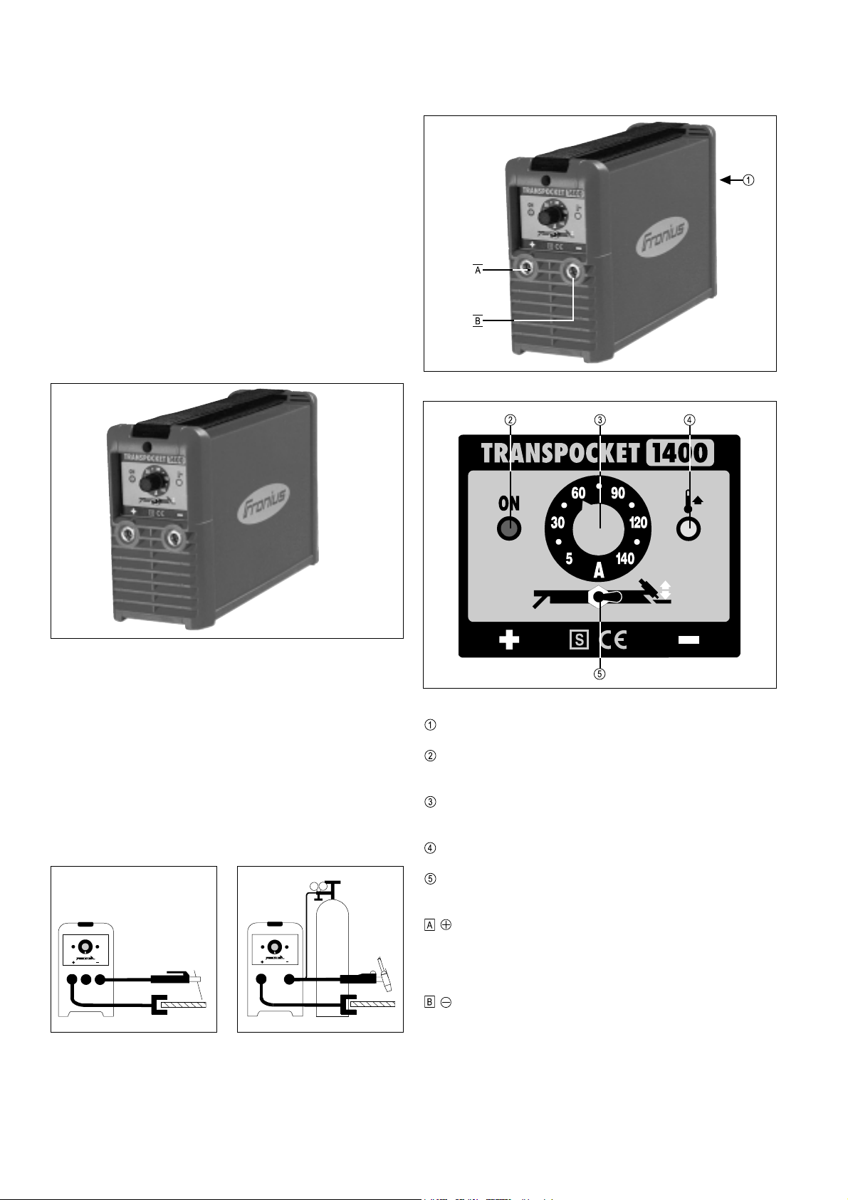
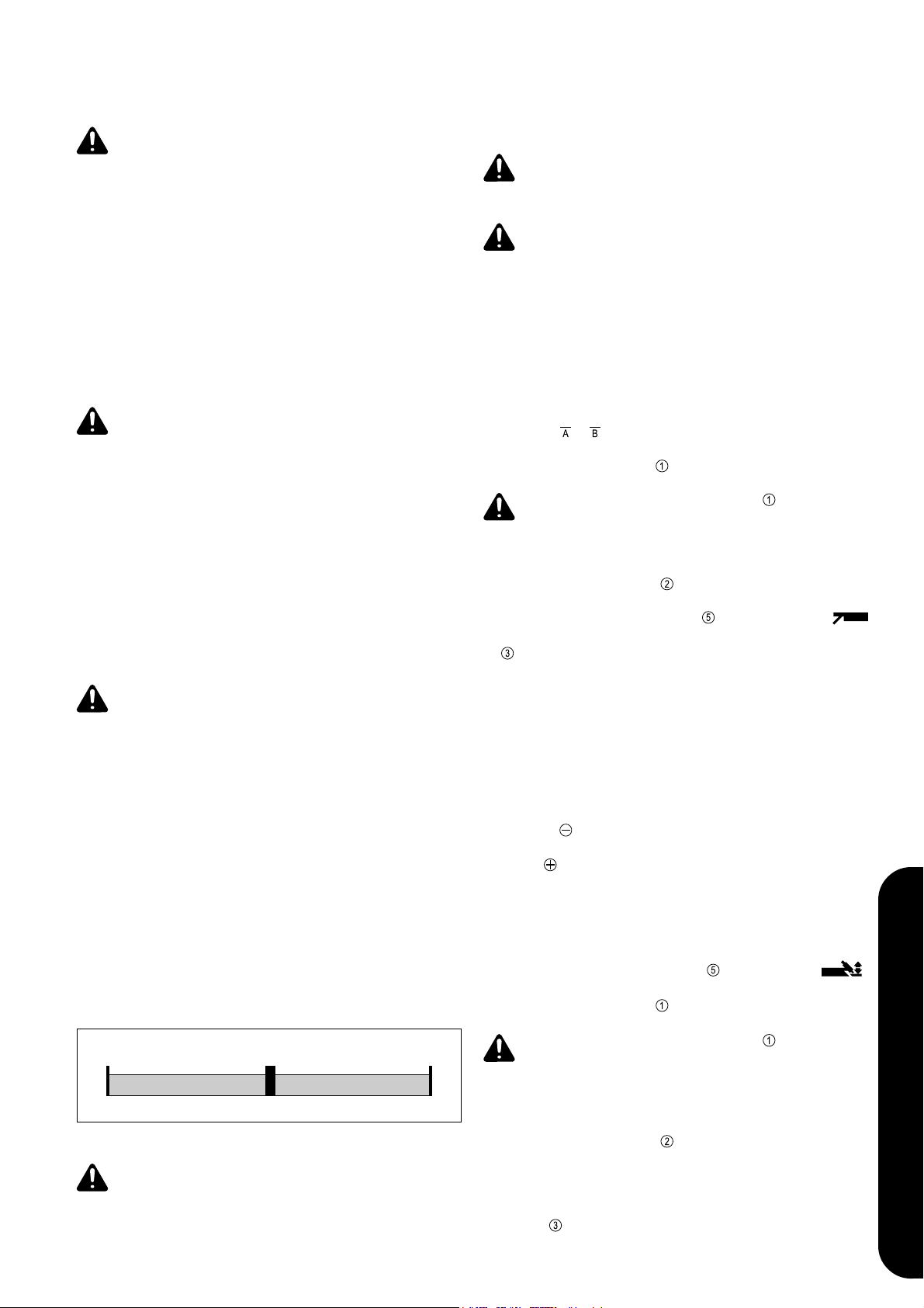
Abb.4 Bedienelemente am Schweißgerät
Abb.1 Schweißgerät TP 1400
GERÄTEKONZEPT
Der TP 1400 hat kleine Abmessungen, ist aber so gebaut, daß er auch unter
harten Einsatzbedingungen zuverlässig funktioniert. Pulverbeschichtetes
Blechgehäuse sowie durch Kunststoffrahmen geschützt angebrachte Bedienungselemente und Anschlußbuchsen mit Bajonettverriegelung gewährleisten höchste Ansprüche. Der Tragegurt ermöglicht einen leichten Transport
sowohl innerbetrieblich als auch beim Einsatz auf Baustellen.
EINSATZGEBIETE
Abb.2 TP 1400 ausgerüstet zum E-
Handschweißen
Abb.3 TP 1400 ausgerüstet zum WIG-
Schweißen
Abb.5 Bedienelemente und Anzeigen am Bedienpanel
Netzschalter
Anzeige Betriebsbereit leuchtet , wenn der Netzhauptschalter auf “1”
geschaltet ist
Einstellregler Schweißstrom ... stufenlose Einstellmöglichkeit des
Schweißstromes
Anzeige Störung leuchtet, wenn das Gerät thermisch überlastet ist
Umschalter Elektrode / WIG ... zur Anwahl des gewünschten Schweiß-
verfahrens
- Strombuchse mit Bajonnetverschluß ... zum Anschluß des
- Handelektroden- bzw. Massekabels beim E-Handschweißen (je nach
Elektrodentype)
- Massekabels beim WIG-Schweißen
- Strombuchse mit Bajonnetverschluß ... zum Anschluß des
- Handelektroden- bzw. des Massekabels beim E-Handschweißen (je
nach Elektrodentype)
- Schweißbrenners beim WIG-Schweißen (Stromanschluß)
6
Page 7
SCHWEISSGERÄT IN BETRIEB NEHMEN
Achtung! Lesen Sie vor Erstinbetriebnahme das Kapitel „Sicherheitsvorschriften“.
BESTIMMUNGSGEMÄSSE VERWENDUNG
Das Schweißgerät ist ausschließlich zum E-Hand- und WIG-Schweißen
bestimmt. Eine andere oder darüber hinausgehende Benutzung gilt als nicht
bestimmungsgemäß. Für hieraus entstehende Schäden haftet der Hersteller
nicht.
Zur bestimmungsgemäßen Verwendung gehört auch
- das Beachten aller Hinweise aus der Bedienungsanleitung
- die Einhaltung der Inspektions- und Wartungsarbeiten
Achtung! Verwenden Sie das Schweißgerät nie zum Auftauen von
Rohren.
AUFSTELLBESTIMMUNGEN
Das Schweißgerät ist nach Schutzart IP23 geprüft, daß bedeutet:
- Schutz gegen Eindringen fester Fremdkörper größer Ø 12mm
- Schutz gegen Sprühwasser bis zu einem Winkel von 60° zur Senkrechten
Sie können das Schweißgerät daher, gemäß Schutzart IP23, im Freien
aufstellen und betreiben. Die eingebauten elektrischen Teile sind jedoch vor
unmittelbarer Nässeeinwirkung zu schützen.
Achtung! Stellen Sie die Schweißanlage auf ebenem und festen
Untergrund standsicher auf. Eine umstürzende Schweißanlage kann
Lebensgefahr bedeuten.
NETZSTECKER ANSCHLIESSEN
Achtung! Netzstecker müssen der Netzspannung und der Stromaufnahme des Schweißgerätes entsprechen (siehe Technische Daten)
Achtung! Die Absicherung der Netzzuleitung ist auf die Stromaufnahme des Schweißgerätes auszulegen
E-HANDSCHWEISSEN
- Schweißkabel je nach Elektrodentype in Strombuchse oder
einstecken und durch Drehen nach rechts verriegeln
- Netzstecker einstecken
- Netzschalter
Achtung! Sobald der Netzschalter
ist die Stabelektrode spannungsführend. Beachten Sie, daß die
Stabelektrode zu diesem Zeitpunkt keine elektrisch leitenden oder
geerdeten Teile wie z.B. Werkstück, Gehäuse, etc. berührt.
- Anzeige Betriebsbereit zeigt den betriebsbereiten Zustand an
- Umschalter Elektrode / WIG
- Stromstärke mit Einstellregler Schweißstrom auswählen
- Schweißung durchführen
in Stellung "I" schalten
in Stellung "I" geschaltet ist,
auf Position Elektrode schalten
DEUTSCH
Der Lüftungskanal stellt eine wesentliche Sicherheitseinrichtung dar. Beachten Sie daher bei der Wahl des Aufstellort, daß die Kühlluft ungehindert durch
die Luftschlitze an Vorder- und Rückseite ein- bzw. austreten kann. Anfallender metallischer Staub (z.B. bei Schmirgelarbeiten) darf nicht direkt in die
Anlage gesaugt werden.
NETZANSCHLUSS
Das Schweißgerät ist für die am Leistungsschild angegebene Netzspannung
ausgelegt. Die Absicherung der Netzzuleitung ist den Technischen Daten zu
entnehmen.
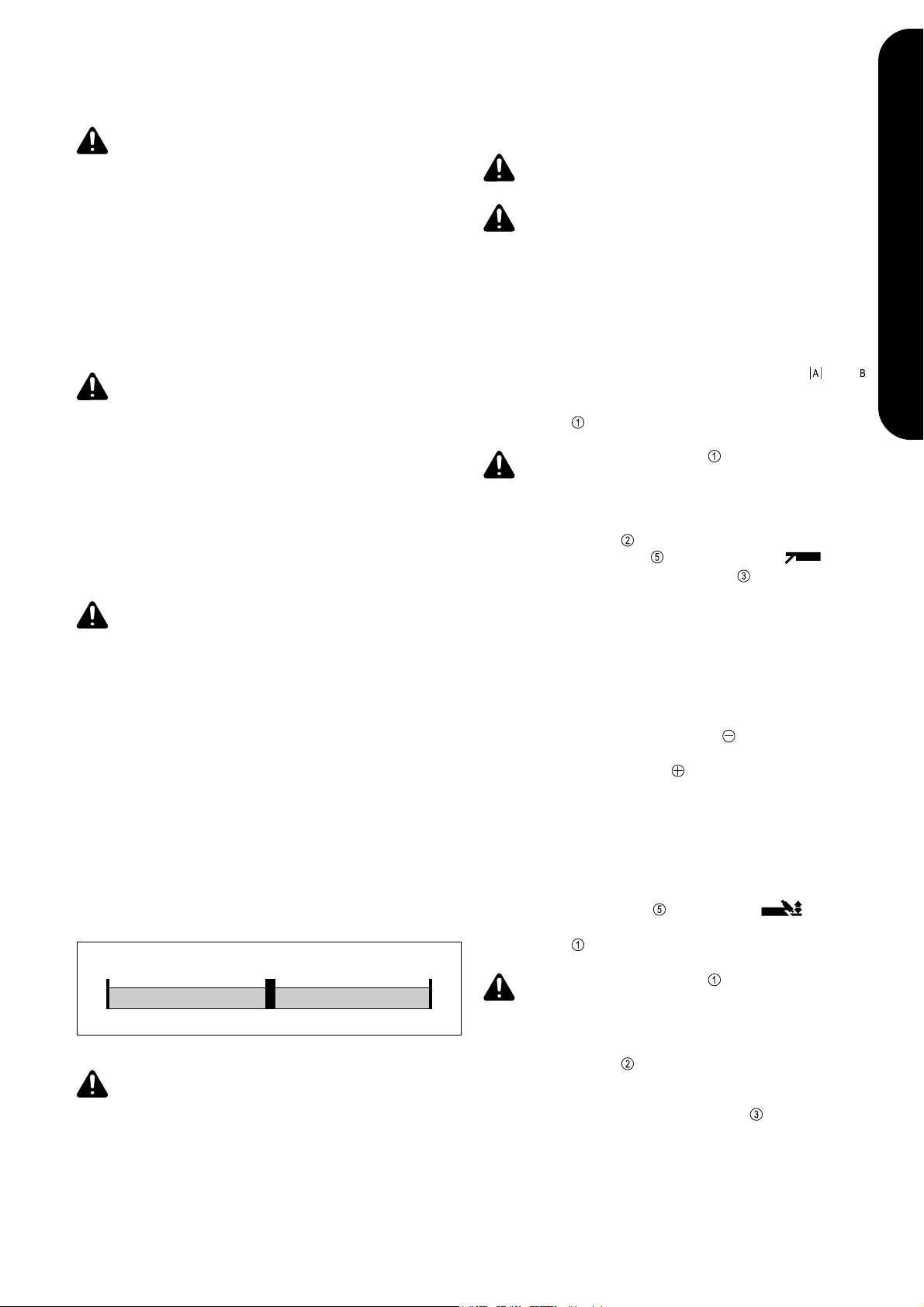
Das Schweißgerät kann serienmäßig mit einer Netzspannung von 230 V~
(+/- 15%) betrieben werden. Bedingt durch den Toleranzbereich von +/- 15%
kann es auch am 220 V~ Netz betrieben werden.
230 V~
-15%
Abb.6 Toleranzbereiche der Netzspannung
Achtung! Ist das Gerät für eine Sonderspannung ausgelegt, gelten
die Technischen Daten am Leistungsschild. Netzstecker, Netzzuleitung sowie deren Absicherung sind entsprechend auszulegen.
+15%
265 V~195 V~
WIG-SCHWEISSEN
- Stromstecker des WIG-Schweißbrenners in - Strombuchse einstecken
und durch Drehen nach rechts verriegeln
- Stromstecker des Massekabels in - Strombuchse einstecken und durch
Drehen nach rechts verriegeln
- Schweißbrenner bestücken (siehe Bedienungsanleitung Schweißbrenner)
- Masseverbindung mit Werkstück herstellen
- Druckregler an der Schutzgasflasche befestigen
- Gasschlauch mit Druckregler verbinden
- Gasflaschenventil öffnen
- Umschalter Elektrode / WIG
- Netzstecker einstecken
- Netzschalter
Achtung! Sobald der Netzschalter in Stellung "I" geschaltet ist,
ist die Wolframelektrode spannungsführend. Beachten Sie, daß die
Wolframelektrode zu diesem Zeitpunkt keine elektrisch leitenden oder
geerdeten Teile wie z.B. Werkstück, Gehäuse, etc. berührt.
- Anzeige Betriebsbereit
- Gasabsperrventil am Schweißbrenner öffnen bzw. Brennertaste drücken
und am Druckregler die gewünschte Gasmenge einstellen
- Schweißstrom mit Einstellregler Schweißstrom auswählen
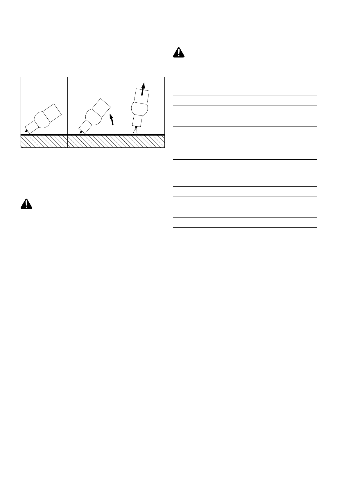
- Gasdüse an der Zündstelle aufsetzen, sodaß zwischen Wolframspitze und
Werkstück 2-3 mm Abstand bestehen (siehe Abb. 7a)
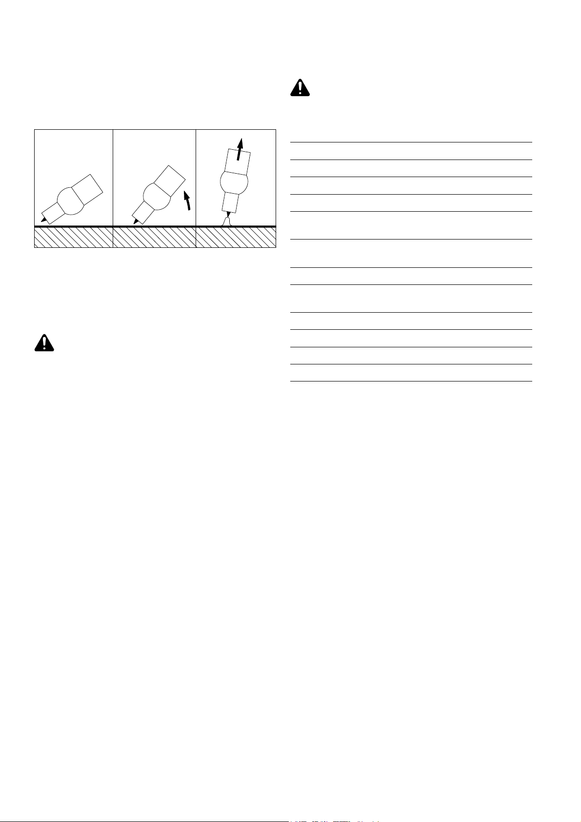
- Schweißbrenner langsam aufrichten bis die Wolframnadel das Werkstück
berührt (siehe Abb. 7b)
- Schweißbrenner anheben und in Normallage schwenken - Lichtbogen
zündet (siehe Abb. 7c)
- Schweißung durchführen
in Stellung "I" schalten
auf Position WIG schalten
zeigt den betriebsbereiten Zustand an
7
Page 8
TECHNISCHE DATEN
Hinweis! Um den Schweißvorgang zu unterbrechen einfach den Schweißbrenner vom Werkstück abheben, bis der Lichtbogen erlischt. Endkraterfüllung durch Stromabsenkung bzw. Gasschutz des Endkraters sind nicht
gegeben.
a) Gasdüse aufsetzen b) Zünden durch
Werkstückberührung
Abb.7 Brenneranstellung
c) Lichtbogen gezündet
PFLEGE UND WARTUNG
Achtung! Vor Öffnen des Schweißgerätes, Gerät abschalten, Netzstecker ziehen und ein Warnschild gegen Wiedereinschalten anbringen - gegebenenfalls Elkos entladen.
Achtung! Ist das Gerät für eine Sonderspannung ausgelegt, gelten
die Technischen Daten am Leistungsschild. Netzstecker, Netzzuleitung sowie deren Absicherung sind entsprechend auszulegen.
Netzspannung 230 V~, 50 - 60 Hz
Netzabsicherung 16 A träge
Cos phi (140 A) 0,99
Wirkungsgrad (bei 100 A) 87 %
Schweißstrombereich El - DC 5 - 140 A
Schweißstrom bei 10min / 40°C 35 % ED 140 A
10min / 40°C 100% ED 100 A
Scheinleistung bei 35 % ED 6,1 kVA
100% ED 3,8 kVA
Leerlaufspannung 93 V
Arbeitsspannung Elektrode 20,2 - 25,6 V
WIG 10,2 - 15,6 V
Schutzart IP 23
Kühlart AF
Isolationsklasse B
Um das Schweißgerät über Jahre hinweg einsatzbereit zu halten sind
folgende Punkte zu beachten:
- Sicherheitstechnische Inspektion laut vorgegebenen Intervallen durchführen (siehe Kapitel „Sicherheitsvorschriften“)
- Je nach Aufstellort, aber mindestens zweimal jährlich, Geräteseitenteile
entfernen und das Schweißgerät mit trockener, reduzierter Druckluft
sauberblasen. Elektronische Bauteile nicht aus kurzer Entfernung anblasen.
- Bei starkem Staubanfall die Kühlluftkanäle reinigen.
S, CE
8
Page 9

FEHLERDIAGNOSE UND -BEHEBUNG
Achtung! Vor Öffnen des Schweißgerätes, Gerät abschalten, Netzstecker ziehen und ein Warnschild gegen Wiedereinschalten anbringen gegebenenfalls Elkos entladen.
Fehler Ursache Behebung
Netzschalter eingeschaltet, Anzeige Betriebsbereit leuchtet nicht
kein Schweißstrom
Netzschalter eingeschaltet, Anzeige Betriebsbereit leuchtet
kein Schweißstrom
Netzschalter eingeschaltet, Anzeige Betriebsbereit leuchtet, Anzeige Störung leuchtet
kein Schweißstrom
Netzschalter eingeschaltet, Anzeige Betriebsbereit leuchtet, Anzeige Störung blinkt
Schlechte Zündeigenschaften beim EHandschweißen
Lichtbogen reißt während des Schweißvorganges fallweise ab
Netzzuleitung unterbrochenkein Schweißstrom
Schweißkabelverbindungen unterbrochen
schlechte - oder keine Masse
Einschaltdauer überschritten - Gerät überlastet
Thermosicherheitsautomatik hat abgeschaltet - Ventilator läuft; Thermofühler defekt
Kühlluftzufuhr unzureichend
Leistungsteil stark verschmutzt
Leistungsteilfehler
falsche Kennlinie angewählt
zu hohe Brennspannung der Elektrode (z.B. NutElektrode)
Netzzuleitung und Netzspannung kontrollieren
DEUTSCH
Steckverbindungen überprüfen
Verbindung zum Werkstück herstellen
Einschaltdauer einhalten
Abkühlphase abwarten; Gerät schaltet nach kurzer Zeit selbständig wieder ein; wenn nicht:
Gerät zum Service
für ausreichende Luftzufuhr sorgen
Gerät öffnen und mit trockener Preßluft ausblasen (siehe Pflege und Wartung!)
Gerät ausschalten und anschließend wieder
einschalten; Fehler tritt erneut auf - Gerät zum
Service
Umschalter Elektrode / WIG auf "Elektrode"
schalten (EL-Kennlinie)
wenn möglich Alternativelektrode verwenden
oder Schweißgerät mit höherer Schweißleistung
einsetzen
Netzsicherung bzw. Sicherungsautomat
fällt
schlechte Schweißeigenschaft
(starke Spritzerbildung)
WIG-Schweißung
Wolframelektrode schmilzt ab - Wolframeinschlüsse im Grundmaterial während der
Zündphase
Netz-Unterspannung
Netz zu schwach abgesichert / falscher Automat
Netzsicherung fällt im Leerlauf
falsche Polung der Elektrode
schlechte Masseverbindung Masseklemmen direkt am Werkstück befestigen
falsche Polung der Wolframelektrode WIG-Schweißbrenner am "- Pol" anschließen
falsches Schutzgas, kein Schutzgas
falsche Kennlinie angewählt
Netzspannung am Gerät messen Zuleitungsquerschnitt erhöhen
Netz richtig absichern (siehe Techn. Daten)
Gerät zum Service
Elektrode umpolen (Angaben des Herstellers
beachten)
Inertes Schutzgas (Argon) verwenden
Umschalter Elektrode / WIG auf "WIG" schalten
(WIG-Kennlinie)
9
Page 10

10
Page 11

OPERATING INSTRUCTIONS
ENGLISH
1
Page 12

2
Page 13

DEAR FRONIUS CUSTOMER
This brochure is intended to familiarise you with how to operate and maintain
your TransPocket 1400 (TP 1400). You will find it well worthwhile to read
through the manual carefully and to follow all the instructions it contains. This
will help you to avoid operating errors - and the resultant malfunctions. Your
machine will repay you by giving you constant operational readiness for many
years to come.
FRONIUS SCHWEISSMASCHINEN
VERTRIEB GMBH & CO KG
Warning! The machine may only be put into service by trained
personnel, and only in accordance with the technical directions.
Before you start using the machine, you must read the section headed
"Safety rules".
CONTENTS
Dear Fronius Customer .............................................................................. 3
Safety rules ................................................................................................ 4
General remarks .................................................................................... 4
Utilisation for intended purpose only ...................................................... 4
Obligations of owner/operator ................................................................ 4
Obligations of personnel ......................................................................... 4
Personal protective equipment ............................................................... 4
Hazards from noxious gases and vapours ........................................... 4
Hazards from flying sparks.................................................................... 4
Hazards from mains and welding current .............................................. 4
Particular danger spots ........................................................................... 4
Informal safety precautions .................................................................... 4
Safety precautions at the installation location ........................................ 5
Safety precautions in normal operation .................................................. 5
Safety inspection .................................................................................... 5
Alterations to the welding machine ........................................................ 5
Spares and wearing parts ...................................................................... 5
Calibration of welding machines ............................................................ 5
CE-marking ............................................................................................ 5
Copyright ................................................................................................ 5
General remarks ......................................................................................... 6
Principle of the TP 1400 ......................................................................... 6
Machine concept .................................................................................... 6
Areas of use ........................................................................................... 6
ENGLISH
Description of controls ................................................................................ 6
Starting to use the power source ............................................................... 7
Utilisation for intended purpose only ...................................................... 7
Machine set-up regulations .................................................................... 7
Mains connection ................................................................................... 7
Plug the machine into the mains ............................................................ 7
Manual electrode welding .......................................................................... 7
TIG welding ................................................................................................ 7
Care and maintenance ............................................................................... 8
Technical Data ............................................................................................. 8
Troubleshooting ........................................................................................... 9
Spare parts list
Circuit diagram
Fronius - Sales and service offices
3
Page 14

SAFETY RULES
GENERAL REMARKS
This welding machine has been made in accordance with the state of the
art and all recognised safety rules. Nevertheless, incorrect operation or
misuse may still lead to danger for
- the life and well-being of the welder or of third parties,
- the welding machine and other tangible assets belonging to the
owner/operator,
- efficient working with the welding machine.
All persons involved in any way with starting up, operating, servicing and
maintaining the welding machine must
- be suitably qualified
- know about welding and
- follow exactly the instructions given in this manual.
Any malfunctions which might impair machine safety must be eliminated
immediately.
It’s your safety that’s at stake!
UTILISATION FOR INTENDED PURPOSE ONLY
The welding machine may only be used for jobs as defined by the
“Intended purpose” (see the section headed "Starting to use the welding
machine").
Utilisation in accordance with the “Intended purpose” also comprises
- following all the instructions given in this manual
- performing all stipulated inspection and servicing work
OBLIGATIONS OF OWNER/OPERATOR
The owner/operator undertakes to ensure that the only persons allowed
to work with the welding machine are persons who
- are familiar with the basic regulations on workplace safety and
accident prevention and who have been instructed in how to operate
the welding machine
- have read and understood the sections on safety and the warnings
contained in this manual, and have confirmed as much with their
signatures
Regular checks must be performed to ensure that personnel are still
working in a safety-conscious manner.
OBLIGATIONS OF PERSONNEL
Before starting work, all persons entrusted with carrying out work on the
welding machine shall undertake
- to observe the basic regulations on workplace safety and accident
prevention
- to read the sections on safety and the warnings contained in this
manual, and to sign to confirm that they have understood these
PERSONAL PROTECTIVE EQUIPMENT
For your personal safety, take the following precautions:
- Wear stout footwear that will also insulate even in wet conditions
- Protect your hands by wearing insulating gloves
- Protect your eyes from UV rays with a safety shield containing
regulation filter glass
- Only use suitable (i.e. flame-retardant) clothing
- Where high noise levels are encountered, use ear-protectors
Where other persons are nearby during welding, you must
- instruct them regarding the dangers,
- provide them with protective equipment and/or
- erect protective partitions or curtains.
HAZARDS FROM NOXIOUS GASES AND VAPOURS
- Extract all fumes and gases away from the workplace, using suitable
means.
- Ensure a sufficient supply of fresh air.
- Keep all solvent vapours well away from the arc radiation.
HAZARDS FROM FLYING SPARKS
- Move all combustible objects well away from the welding location.
- Welding must NEVER be performed on containers that have had
gases, fuels, mineral oils etc. stored in them. Even small traces of
these substances left in the containers are a major explosion hazard.
- Special regulations apply to rooms at risk from fire and/or explosion.
Observe all relevant national and international regulations.
HAZARDS FROM MAINS AND WELDING CURRENT
- An electric shock can be fatal. Every electric shock is hazardous to
life.
- Magnetic fields generated by high amperages may impair the functioning of vital electronic devices (e.g. heart pacemakers). Users of
such devices should consult their doctors before going anywhere
near the welding workplace.
- All welding cables must be firmly attached, undamaged and properly
insulated. Replace any loose connections and scorched cables immediately.
- Have the mains and the appliance supply leads checked regularly by
a qualified electrician to ensure that the PE conductor is functioning
correctly.
- Before opening up the welding machine, make absolutely sure that
this is "dead". Discharge any components that may store an electrical
charge.
- If work needs to be performed on any live parts, there must be a
second person on hand to switch of the machine at the main switch
in an emergency.
PARTICULAR DANGER SPOTS
- Do not put your fingers anywhere near the rotating toothed wheels of
the wirefeed drive.
- Special regulations apply to rooms at risk from fire and/or explosion.
Observe all relevant national and international regulations.
- Welding machines for use in spaces with increased electrical danger
(e.g. boilers) must be identified by the “S” (for safety) mark.
- Welding-joins to which special safety requirements apply must only
be carried out by specially trained welders.
- When hoisting the power source by crane, always attach the chains
or ropes to the hoisting lugs at as close an angle to the vertical as
possible. Before hoisting, remove the gas cylinder and the wirefeed
unit.
- When hoisting the wirefeed unit by crane, always use an insulating
suspension arrangement.
INFORMAL SAFETY PRECAUTIONS
- The instruction manual must be kept at the welding-machine location
at all times.
4
Page 15

- In addition to the instruction manual, copies of both the generally
applicable and the local accident prevention and environmental
protection rules must be kept on hand, and of course observed in
practice.
- All the safety instructions and danger warnings on the welding
machine itself must be kept in a legible condition.
ALTERATIONS TO THE WELDING MACHINE
- Do not make any alterations, installations or modifications to the
welding machine without getting permission from the manufacturer
first.
- Replace immediately any components that are not in perfect condition.
SAFETY PRECAUTIONS AT THE INSTALLATION
LOCATION
- The welding machine must be placed on an even, firm floor in such a
way that it stands firmly. A welding machine that topples over can
easily kill someone!
- Special regulations apply to rooms at risk from fire and/or explosion.
Observe all relevant national and international regulations.
- By means of internal instructions and checks, ensure that the workplace and the area around it are always kept clean and tidy.
VAGRANT WELDING CURRENTS
- Ensure the workpiece clamp is connected tightly to the workpiece
- Set the welding machine up insulated where the floor conducts
electricity
If these instructions are not followed vagrant welding currents occur,
these can destroy earthed conductor terminals and other electrical
equipment.
SAFETY PRECAUTIONS IN NORMAL OPERATION
- Only operate the welding machine if all its protective features are fully
functional.
- Before switching on the welding machine, ensures that nobody can
be endangered by your turning on the machine.
- At least once a week, check the machine for any damage that may be
visible from the outside, and check that the safety features all function
correctly.
SAFETY INSPECTION
The owner/operator is obliged to have the machine checked for proper
condition by a trained electrician after any alterations, installations of
additional components, modifications, repairs, care and maintenance,
and in any case at least every twelve months.
SPARES AND WEARING PARTS
- Use only original spares and wearing parts. With parts sourced from
other suppliers, there is no certainty that these parts will have been
designed and manufactured to cope with the stressing and safety
requirements that will be made of them.
- When ordering spare parts, please state the exact designation and
the relevant part number, as given in the spare parts list. Please also
quote the serial number of your machine.
CALIBRATION OF WELDING MACHINES
In view of international standards, regular calibration of welding machinery is advisable. Fronius recommends a 12-month calibration interval.
For more information, please contact your Fronius partner!
CE-MARKING
The welding machine fulfils the fundamental requirements of the LowVoltage and Electromagnetic Compatibility Directive and is thus CEmarked.
COPYRIGHT
Copyright to this instruction manual remains the property of Fronius
International GmbH&Co.KG.
Text and illustrations are all technically correct at the time of going to
print. Right to effect modifications is reserved. The contents of the
instruction manual shall not provide the basis for any claims whatever on
the part of the purchaser. If you have any suggestions for improvement,
or can point out to us any mistakes which you may have found in the
manual, we should be most grateful.
ENGLISH
In the course of such inspection, the following regulations must be
observed (as a minimum):
- IEC (EN) 60 974-1 - Arc welding equipment - Part 1: Welding power
sources
- VBG 4, §5 - Electrical plant and apparatus
- VBG 15, §33 / §49 - Welding, cutting and allied processes
- VDE 0701-1 - Repair, modification and inspection of electrical
appliances; general requirements
- VDE 0702-1 - Repeat tests on electrical appliances
Further information on corrective maintenance, modification and
inspection of welding machines is available from your regional or national
Fronius service centre,who will be pleased to provide you with a copy of
the Work Instruction “Safety Inspection of Welding Machinery” (AAPMÜ-01) upon request.
ud_fr_st_sv_00146 0120015
Page 16
GENERAL REMARKS
PRINCIPLE OF THE TP 1400
The TP 1400 is a further member of the new generation of welding rectifiers.
High-performance electronics have helped create a truly unique rectifier that
weighs in at a mere 4.4 kg.
The voltage from the mains is first rectified. A high-speed transistor switch
chops this direct voltage at a frequency of up to 100 kHz. The welding
transformer then creates the required operating voltage, which is rectified and
delivered to the output sockets. An electronic controller adjusts the powersource characteristic to the electrode that is to be welded.
The unit’s compact dimensions, low weight and very modest power consumption are real advantages in its favour. Its superb ignition and welding
properties, coupled with the fact that it can also be used as a TIG welding
machine, extend its range of use and application still further.
DESCRIPTION OF CONTROLS
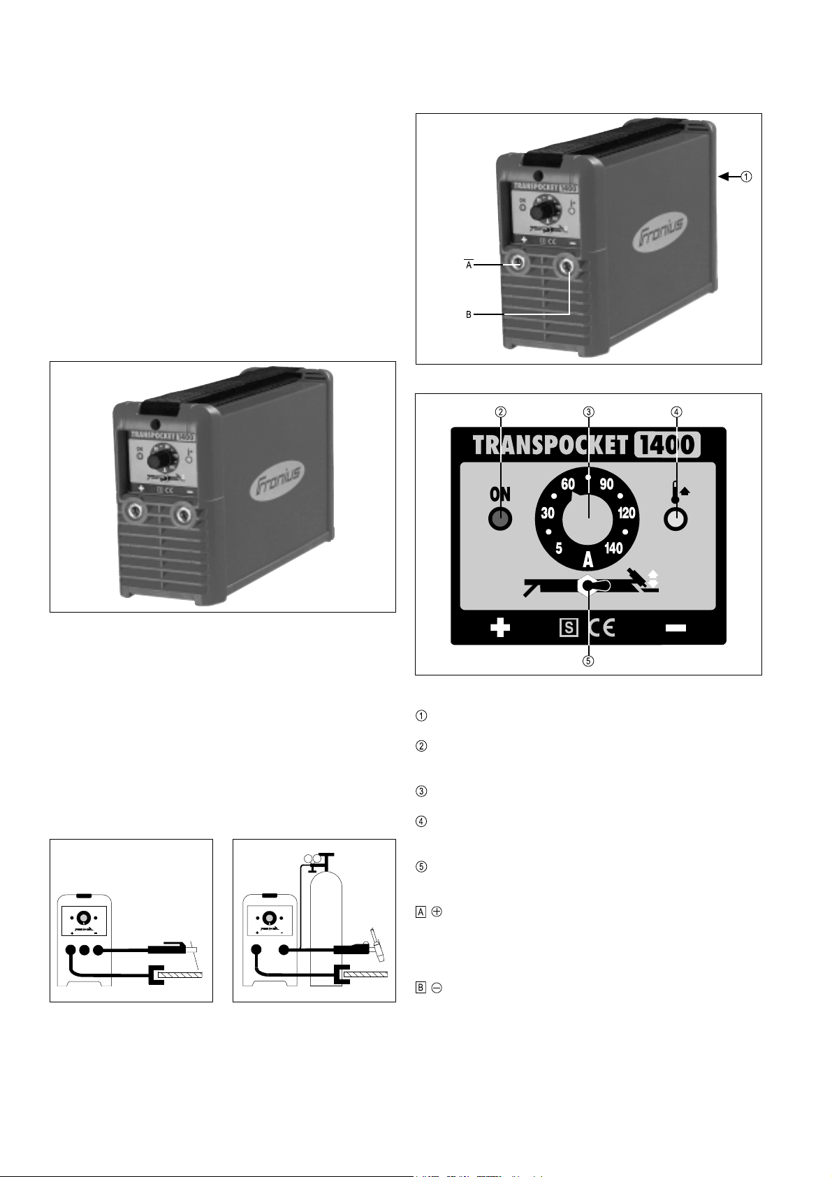
Fig.4 Controls on the welding machine
Fig.1 TransPocket 1400
MACHINE CONCEPT
The TP 1400 may only be small, but it is built to function dependably under
even the toughest operating conditions. Features such as its powder-coated
sheet-steel housing, the way its controls are protected by a plastic frame, and
its bayonet-latching connection sockets all testify to the high quality of its
design. Thanks to its carrying strap, the machine is easy to move around both in the workshop and out in the field.
AREAS OF USE
Fig.2 TransPocket 1400 as a manual
electrode welding unit
Fig.3 TransPocket 1400 as a TIG
welding unit
Fig.5 Controls and indicators on the operating panel
Mains switch
Operational readiness indicator lights up when the mains switch is
shifted to “1”
Welding current dial ... for continuous adjustment of the welding current
Malfunction indicator ... lights up when the unit is thermally overloaded
(i.e. overheats)
Electrode / TIG changeover switch ... for selecting the desired welding
process
- Current socket with bayonet latch ... for connecting:
- Manual electrode or earthing cable for manual electrode welding
(depending on type of electrode)
- Earthing cable for TIG welding
- Current socket with bayonet latch ... for connecting:
- Manual electrode or earthing cable for manual electrode welding
(depending on type of electrode)
- Welding torch for TIG welding (current connection)
6
Page 17

STARTING TO USE THE POWER
SOURCE
Warning! Before starting to use for the first time, read the section
headed “Safety rules”.
UTILISATION FOR INTENDED PURPOSE ONLY
The welding machine is intended to be used SOLELY for rod electrode and TIG
welding. Any other use, or any use going beyond the above, is deemed to be
“not for the intended purpose” and the manufacturer shall not be liable for any
damage resulting therefrom.
Utilisation for the intended purpose” shall also be deemed to encompass:
- the observance of all instructions in the operating manual
- the carrying out of all prescribed inspection and maintenance work
Warning! Never use the welding machine for thawing frozen pipes!
MACHINE SET-UP REGULATIONS
The welding machine is tested to “Degree of protection IP23”, meaning:
- Protection against penetration by solid foreign bodies with diameters larger
than 12 mm
- Protection against spraywater up to an angle of 60° to the upright
The welding machine can be set up and operated outdoors in accordance with
IP23. However, the built-in electrical components must be protected against
direct wetting.
Caution! The fuse protection for the mains lead should be suitable for
the current consumption of the welding machine!
MANUAL ELECTRODE WELDING
- Plug the welding cable into current socket or , depending on the type
of electrode, and turn it clockwise to latch it
- Plug the machine into the mains
- Shift the mains switch
Warning! As soon as you shift the mains switch
position, the rod electrode becomes LIVE. Make sure that when this
happens, the rod electrode does not touch any electrically conducting
or earthed parts such as e.g. the workpiece, machine housing etc.
- The operational readiness indicator comes on to show that the machine
is ready for operation
- Shift the Electrode / TIG changeover switch
- Select the desired amperage on the welding current dial
- Start welding
into the "I" position
into the "I"
to the electrode position
Warning! Place the welding machine on an even, firm floor in such
a way that it stands firmly. A welding machine that topples over can
easily kill someone!
The venting duct is a very important safety feature. When choosing the
machine location, make sure that it is possible for the cooling air to enter and
exit unhindered through the louvers on the front and back of the machine. Any
metallic dust from e.g. grinding-work must not be allowed to get sucked into
the machine.
MAINS CONNECTION
The welding machine is designed to run on the mains voltage given on the
rating plate. The mains cable and plug are ready-mounted. For details of fuse
protection of the mains supply lead, please see the Technical Data.
The machine can be run as standard on a mains voltage of 230 V~ (+/- 15%).
Thanks to its +/-15% tolerance range, it can also be run on the 220 V~ mains.
230 V~
-15%
Fig.6 Tolerance ranges of the mains voltage
Warning! If the machine is designed to run on a special voltage, the
Technical Data shown on the rating plate apply. The mains plug and
mains supply lead, and their fuse protection, must be dimensioned
accordingly.
+15%
265 V~195 V~
PLUG THE MACHINE INTO THE MAINS
Caution! The mains plug used must correspond exactly to the mains
voltage and current rating of the welding machine in question, as given
in the Technical Data!
TIG WELDING
- Insert the current plug of the TIG welding torch into the - current socket
and turn it clockwise to latch it
- Insert the current plug of the earthing cable into the - current socket and
turn it clockwise to latch it
- Set up the welding torch (see the Instruction Manual for your torch)
- Make an earthing connection to the workpiece
- Attach a pressure regulator to the shielding-gas cylinder
- Connect the gas-hose to the pressure regulator
- Open the valve on the gas cylinder
- Shift the Electrode / TIG changeover switch
- Plug the machine into the mains
- Shift the mains switch into the "I" position
Warning! As soon as you shift the mains switch
position, the tungsten electrode becomes LIVE. Make sure that when
this happens, the tungsten electrode does not touch any electrically
conducting or earthed parts such as e.g. the workpiece, machine
housing etc.
- The operational readiness indicator
is ready for operation
- Open the gas cut-off valve on the torch and/or press the torch trigger and
set the desired gas flow rate on the pressure regulator
- Select the desired amperage on the welding current dial
- Place the gas nozzle on the ignition location so that there is a gap of 2 3 mm between the tungsten tip and the workpiece (see Fig. 7a)
- Gradually tilt up the welding torch until the tungsten tip touches the
workpiece (see Fig. 7b)
- Raise the torch and pivot it into the normal position - the arc ignites (see
Fig. 7c)
- Start welding
to the TIG position
into the "I"
comes on to show that the machine
ENGLISH
7
Page 18
N.B.! To interrupt the welding operation, simply lift the torch away from the
workpiece until the arc goes out. In this case, there will be no filling of the endcrater at reduced current, and no gas-shielding of the end-crater.
TECHNICAL DATA
Warning! If the machine is designed to run on a special voltage, the
Technical Data shown on the rating plate apply. The mains plug and
mains supply lead, and their fuse protection, must be dimensioned
accordingly.
a) Fit gas nozzle b) Touch workpiece to
ignite arc
Fig.7 Torch tilt angle
c) Arc is ignited
CARE AND MAINTENANCE
Warning! Before opening up the welding machine, switch it off, unplug
it from the mains and put up a warning sign to stop anybody
inadvertently switching it back on again. If necessary, discharge the
electrolytic capacitors.
In order to keep your welding machine operational for years to come, you
should observe the following points:
- Carry out safety inspections at the stipulated intervals (see the section
headed “Safety rules”)
- Depending on the machine location, but no less often than twice a year,
remove the side panels from the machine and blow the inside of the
machine clean with dry, reduced-blow compressed air. Do not aim airjets at electronic components from too close a range.
- If a lot of dust has accumulated, clean the cooling-air ducts.
Mains voltage 230 V~, 50 - 60 Hz
Mains fuse 16 A slow
Cos phi (140 A) 0.99
Efficiency (at 100 A) 87 %
Welding current range El - DC 5 - 140 A
Welding current at 10min / 40°C 35 % d.c. 140 A
10min / 40°C 100% d.c. 100 A
Apparent power at 35 % d.c. 6.1 kVA
100% d.c. 3.8 kVA
Open-circuit voltage 93 V
Operating voltage Electrode 20.2 - 25.6 V
TIG 10.2 - 15.6 V
Protection class IP 23
Type of cooling AF
Insulation category B
S, CE
8
Page 19

TROUBLESHOOTING
Warning! Before opening up the welding machine, switch it off, unplug it from the mains and put up a warning sign to stop anybody inadvertently
switching it back on again. If necessary, discharge the electrolytic capacitors.
Error Cause Remedy
Mains switch is ON, operational readiness
indicator not lit up
No welding current
Mains switch is ON, operational readiness
indicator is lit up
No welding current
Mains switch is ON, operational readiness
indicator is lit up, malfunction indicator is lit up
No welding current
Mains switch is ON, operational readiness
indicator lights up, malfunction indicator flashes
Poor ignition characteristics
when used for manual-electrode welding
Arc sometimes breaks during the welding
process
Break in mains leadNo welding current
Break in welding cable connection
Faulty or broken earth connection
Maximum duty cycle exceeded - machine overloaded
Thermostatic cut-out system has tripped - fan is
running; temperature sensor is faulty
Insufficient cooling air reaching machine
Power module is very dirty
Fault in power section
Wrong characteristic has been selected
Arc-drop voltage of electrode too high (e.g. grooved
electrode)
Check mains lead and mains voltage
Check plug-in connections
Earth workpiece
Observe duty cycle
Wait until cooling down period is over, machine
will switch on automatically - if not: machine
should be serviced
Ensure sufficient supply of cooling air
Remove cover of machine and clean out with
compressed air (see "Care and Maintenance")
Switch machine off and back on again. If fault
recurs - send machine in for service
Shift Electrode / TIG changeover switch to
Electrode (EL characteristic)
If possible, use different type of electrode or a
machine capable of delivering greater welding
current
Mains fuse and/or safety cut-out has
tripped
Poor welding characteristic (high degree of
spattering)
TIG welding
Tungsten electrode melts off; tungsten inclusions
in the base metal during ignition
Mains undervoltage
Mains fuse too weak; incorrect safety cut-out
Mains fuse is tripped under no-load conditions Machine should be serviced
Incorrect electrode polarity
Poor earth connection Fix earth clamp directly on to the work-piece
Incorrect electrode polarity
Wrong shielding gas, no shielding gas
Wrong characteristic has been selected
Measure mains voltage at machine, increase the
cross-sectional area of the supply lead
Insert correct fuse (see technical data)
Reverse polarity - Note manufacturer´s instructions
Connect TIG welding torch to "- pole"
Use inert shielding gas (argon)
Shift Electrode / TIG changeover switch to TIG
(TIG characteristic)
ENGLISH
9
Page 20

10
Page 21

MODE D´EMPLOI
FRANÇAIS
1
Page 22

2
Page 23

CHER CLIENT DE FRONIUS,
La brochure présente est destinée à vous familiariser avec la commande et
l’entretien de la TransPocket 1400 (TP 1400). C’est dans votre intérêt de lire
attentivement le mode d’emploi et d’observer scrupuleusement les instructions y mentionnées. Ainsi vous éviterez des pannes dues à des fautes de
manipulation. L’appareil vous en récompensera par une disponibilité permanente et une longue vie.
FRONIUS SCHWEISSMASCHINEN
VERTRIEB GMBH & COKG
Attention! Seules des personnes qualifiées sont autorisées à effectuer la mise en service de l‘appareil et ceci uniquement dans le cadre
de la réglementation technique. Lisez attentivement le chapitre „Consignes de sécurité“ avant de procéder à la mise en service.
MODE D'EMPLOI
Cher client de Fronius, ............................................................................... 3
Consignes de sécurité ............................................................................... 4
Safety rules ................................................................................................ 4
Généralités.............................................................................................. 4
Uilisation conforme ................................................................................. 4
Obligations de l‘exploitant ...................................................................... 4
Obligations du personnel ........................................................................ 4
Equipement de protection individuel ...................................................... 4
Risque provenant du dégagement de vapeurs et gaz de nocifs ........... 4
Risques provenant de la projection d‘étincelles .................................... 4
Risques provenant du courant secteur et du courant de soudage ........ 4
Zones particulièrement dangereuses ...................................................... 4
Mesures de sécurité relatives à l‘information ........................................ 5
Mesures de sécurité sur le lieu d‘installation de la soudeuse ............... 5
Mesures de sécurité en fonctionnement normal .................................... 5
Contrôle de sécurité ............................................................................... 5
Modifications apportées à la soudeuse .................................................. 5
Pièces de rechange et pièces d‘usure .................................................. 5
Etalonnage de postes à souder .............................................................. 5
Label CE ................................................................................................ 5
Droits d‘auteur ........................................................................................ 5
Generalites .................................................................................................. 6
Principe ................................................................................................... 6
Construction de l’appareil ....................................................................... 6
Champs d'application ............................................................................. 6
Description des elements de commande ................................................... 6
Mise en service du poste de soudage....................................................... 7
Utilisation conforme a la destination prevue .......................................... 7
Consignes concernant l'installation ........................................................ 7
Raccordement au secteur ....................................................................... 7
Brancher la fiche secteur ....................................................................... 7
Soudage manuel a l'electrode .................................................................... 7
Soudage TIG .............................................................................................. 7
.................................................................................................................... 7
Entretien ...................................................................................................... 8
Donnees Techniques .................................................................................. 8
Pannes: Diagnostic et remedes ................................................................. 9
Liste de pièces de rechange
Schema de connexions
Fronius - Bureaux de vente et bureaux de service
FRANÇAIS
3
Page 24

CONSIGNES DE SÉCURITÉ
GÉNÉRALITÉS
La soudeuse répond aux derniers développements techniques et satisfait à la réglementation généralement reconnue en matière de sécurité.
En cas de fausse manoeuvre ou de mauvaise utilisation, elle présente
toutefois certains risques
- pour la santé et la vie de l‘utilisateur ou d‘un tiers,
- pour l‘appareil et pour d‘autres biens matériels de l‘exploitant,
- liés à la qualité du travail effectué avec la soudeuse.
Toutes les personnes intervenant dans la mise en service, la manipulation et l‘entretien de la soudeuse doivent
- avoir la qualification requise,
- avoir des connaissances suffisantes en soudure et
- observer scrupuleusement les instructions de service.
Tout dérangement susceptible d‘affecter la sécurité doit être réparé sans
délai.
Votre sécurité est en jeu !
UILISATION CONFORME
La soudeuse a été conçue exclusivement pour une utilisation de le cadre
des travaux prévus (voir chapitre „Mise en service de l’appareil de
soudage“).
L‘utilisation conforme implique également l‘observation
- de toutes les consignes figurant dans les instructions de service
- des travaux d‘inspection et d‘entretien prescrits.
OBLIGATIONS DE L‘EXPLOITANT
L‘exploitant s‘engage à n‘autoriser l‘utilisation de la soudeuse qu‘à des
personnes
- connaissant les prescriptions fondamentales concernant la sécurité
du travail et la prévention d‘accidents et familiarisées avec la manipulation de la soudeuse
- ayant lu et compris les avertissements figurant dans ces instructions
de service, et l‘ayant confirmé en apposant leur signature.
L‘exploitant est tenu de contrôler régulièrement si le personnel travaille
en respectant les prescriptions en matière de sécurité.
OBLIGATIONS DU PERSONNEL
Toutes les personnes chargées de travailler avec la soudeuse s‘engagent à
- respecter les prescriptions fondamentales en matière de sécurité du
travail et de prévention des accidents,
- à lire le chapitre concernant la sécurité ainsi que les avertissements
figurant dans les présentes instructions de service et à attester par
leur signature qu‘ils les ont compris, ceci avant d‘entamer le travail.
EQUIPEMENT DE PROTECTION INDIVIDUEL
Prenez les dispositions suivantes pour préserver votre sécurité :
- portez des chaussures solides, isolantes. Ces chaussures doivent
rester isolantes même dans un environnement humide
- protégez les mains par des gants isolants
- protégez les yeux des rayons ultraviolets en utilisant un écran de
soudeur doté de verres filtrants réglementaires
- portez uniquement des vêtements appropriés (difficilement inflammables)
- en cas de production importante de bruit, portez un casque antibruit
Toutes les personnes se trouvant dans le voisinage de l‘arc électrique
doivent
- être informées des dangers
- équipées des moyens de protection adéquats ;
- si nécessaire, prévoir des cloisons ou tentures de protection.
RISQUE PROVENANT DU DÉGAGEMENT DE
VAPEURS ET GAZ DE NOCIFS
- Prévoir un système d‘aspiration adéquat pour évacuer les fumées et
gaz nocifs de la zone de travail.
- Veiller à une ventilation suffisante.
- Eviter que les vapeurs dégagées par des solvants pénétrent dans la
zone de rayonnement de l‘arc électrique.
RISQUES PROVENANT DE LA PROJECTION
D‘ÉTINCELLES
- Eloigner tout objet inflammable de la zone de travail.
- Il est interdit de souder sur des réservoirs contenant ou ayant contenu
des gaz, des carburants, des huiles minérales et substances analogues. Même des résidus de ces substances présentent un risque
d‘explosion.
- Dans les locaux exposés au risque d‘incendie ou d‘explosion, une
réglementation particulière est applicable. Respecter la réglementation nationale et internationale qui s‘y rapporte.
RISQUES PROVENANT DU COURANT SECTEUR ET
DU COURANT DE SOUDAGE
- Une décharge électrique peut avoir des conséquences graves. En
principe, toute décharge peut être mortelle.
- Les champs magnétiques générés par de fortes intensités de courant
peuvent affecter le fonctionnement d‘appareils électroniques vitaux
(par exemple, stimulateurs cardiaques). Les personnes porteuses
d‘appareils de ce genre devraient consulter leur médecin avant de se
tenir à proximité immédiate d‘une zone de soudage.
- Tous les câbles de soudage doivent être bien fixés, intacts et isolés.
Remplacer immédiatement tout raccord lâche ou câble brûlé.
- Faire vérifier régulièrement par un électricien professionnel le conducteur de terre de la ligne d‘alimentation secteur et la ligne
d‘alimentation de l‘appareil.
- Avant d‘ouvrir l‘appareil à souder, s‘assurer qu‘il ne puisse pas être
accidentellement rebranché. Décharger les composants susceptibles d‘être électriquement chargés.
- Au cas où des interventions sur des éléments sous tension seraient
nécessaires, il est indispensable de faire appel à une seconde
personne qui puisse, le cas échéant, couper l‘alimentation électrique.
ZONES PARTICULIÈREMENT DANGEREUSES
- Ne jamais approcher les doigts des roues dentées du système
d‘entraînement du fil lorsqu‘il est en fonctionnement.
- Dans les locaux exposés au risque d‘incendie ou d‘explosion, une
réglementation particulière est applicable. Respecter la réglementation nationale et internationale qui s‘y rapporte.
- Les soudeuses destinées aux travaux dans des locaux à risques
électriques accrus (p. ex. chaudières) doivent être pourvus du label
S (Safety).
- Les soudures exigeant des mesures de sécurité particulières doivent
obligatoirement être réalisées par des soudeurs ayant reçu la formation adéquate.
4
Page 25

- Lors du transport par grue de la source de courant, toujours accrocher
les chaînes ou les câbles dans les anneaux de levage en gardant un
angle le plus perpendiculaire possible. Retirer la bouteille de gaz et
l‘unité d‘entraînement du fil.
- Lors du transport par grue de l‘unité d‘entraînement du fil, toujours
utiliser une suspension isolante.
MESURES DE SÉCURITÉ RELATIVES À
L‘INFORMATION
- Les instructions de service doivent être conservées en permanence
sur le lieu d‘utilisation de la soudeuse.
- En complément aux instructions de service, la réglementation généralement valable et la réglementation locale concernant la prévention d‘accidents et la protection de l‘environnement doivent à tout
moment être disponibles et respectés.
- Toutes les consignes de sécurité et les avertissements de danger
apposés sur la soudeuse doivent rester lisibles.
MESURES DE SÉCURITÉ SUR LE LIEU
D‘INSTALLATION DE LA SOUDEUSE
- Le poste à souder doit être installé sur un sol ferme et plat offrant
suffisamment de stabilité. Le renversement de la soudeuse présente
un grave danger !
- Dans les locaux exposés au risque d‘incendie ou d‘explosion, une
réglementation particulière est applicable. Respecter la réglementation nationale et internationale qui s‘y rapporte.
- Assurer par des directives et des contrôles internes que l‘environnement du lieu de travail soit toujours propre et ordonné.
COURANTS DE SOUDAGE VAGABONDS
- Veiller à une liaison solide de la pince à pièces usinées avec la pièce
usinée
- Lorsque le fond est conducteur électriquement, mise en place, si
possible, de l’appareil de soudage de sorte à l’isoler
En cas d’inobservation, des courants de soudage vagabonds surviennent pouvant conduire à la destruction de conducteurs de protection, de
l’appareil de soudage et d’autres installations électriques.
MESURES DE SÉCURITÉ EN FONCTIONNEMENT
NORMAL
- N‘utiliser la soudeuse que si tous les dispositifs de sécurité fonctionnent.
- Avant la mise en circuit de l‘appareil, s‘assurer que personne ne peut
être mis en danger.
- Au moins une fois par semaine, vérifier si la soudeuse ne présente
aucune détérioration détectable de l‘extérieur et contrôler le
fonctionnement des dispositifs de sécurité.
- VBG 4, §5 - Installations électriques et matériel électrique
- VBG 15, §33 / §49 - Soudure, découpage et opérations analogues
- VDE 0701-1 - Réparation, modification et contrôle d‘appareils électriques; exigences générales
- VDE 0702-1 - Essais de répétition sur les appareils électriques
Pour des renseignements plus précis concernant la mise en service, la
modification et l‘essai de postes de soudage, veuillez demander
l‘instruction de travail „Inspection de sécurité d‘appareils de soudage“
(AA-PMÜ-01) à votre poste de service Fronius.
MODIFICATIONS APPORTÉES À LA SOUDEUSE
- Aucune modification, transformation ou montage ne peuvent être
effectués sur la soudeuse sans l‘autorisation du constructeur.
- Remplacer immédiatement tout composant présentant un défaut
quelconque.
PIÈCES DE RECHANGE ET PIÈCES D‘USURE
- N‘utiliser que des pièces de rechange ou des pièces d‘usure d‘origine.
Les pièces d‘autres fabricants n‘offrent pas les garanties de sécurité
et de fonctionnement suffisantes.
- Pour toute commande, prière d‘indiquer la dénomination et le numéro
de référence exacts, comme indiqués sur la liste des pièces de
rechange, ainsi que le numéro de série de l‘appareil.
ETALONNAGE DE POSTES À SOUDER
Les normes internationales préconisent l‘étalonnage à intervalle régulier
des postes à souder. Fronius recommande d‘effectuer cet étalonnage
tous les 12 mois. Si vous désirez de plus amples informations à ce sujet,
n‘hésitez pas à contacter votre concessionnaire Fronius !
LABEL CE
La soudeuse satisfait aux exigences fondamentales de la directive en
matière de basse tension et de compatibilité électromagnétique et a
obtenu le label CE.
DROITS D‘AUTEUR
La société Fronius International GmbH&Co.KG est propriétaire des
droits d‘auteurs sur ces instructions de service.
Le texte et les figures correspondent à l‘état de la technique au moment
de la mise sous presse. Sous réserve de modification. Le contenu des
présentes instructions de service ne fondent aucun recours de la part de
l‘acheteur. Nous sommes reconnaissants pour toute proposition
d‘amélioration ou indication d‘erreurs figurant dans les instructions de
service.
CONTRÔLE DE SÉCURITÉ
Après toute modification, réparation, ou entretien de la soudeuse et au
moins une fois tous les douze mois, l‘exploitant est tenu de faire effectuer
un contrôle de état par un électricien professionnel.
Pour la vérification, tenir compte des prescriptions suivantes :
- IEC (EN) 60 974-1 - Matériel de soudage électrique - Partie 1:
Sources de courant pour soudage
FRANÇAIS
5
ud_fr_st_sv_00147 012001
Page 26
GENERALITES
PRINCIPE
Le TP 1400 est un membre supplémentaire de la nouvelle génération de
redresseurs de soudage. L'utilisation de l’électronique haute performance a
permis la création d'un redresseur exceptionnelde seulement 4,4 kg.
La tension du courant secteur est redressée. Un interrupteur à transistor rapide
vient ensuite hacher cette tension continue à une fréquence de jusqu'à 100
kHz. Après avoir traversé le transformateur de soudage, la tension obtenue
est la tension de travail désirée qui est redressée et fournie aux douilles de
sortie. Un régulateur électronique adapte la caractéristique de la source de
courant à l'électrode de soudage.
Dimensions minimales, poids réduit et faible consommation d’énergie sont des
atouts importants, très avantageux pour l'utilisateur. Les excellentes caractéristiques d’amorçage et de soudage ainsi que les possibilités de la
commutation TIG élargissent son champ d’utilisation et d’application.
DESCRIPTION DES ELEMENTS DE
COMMANDE
Fig.4 Eléments de commande sur le poste de soudage
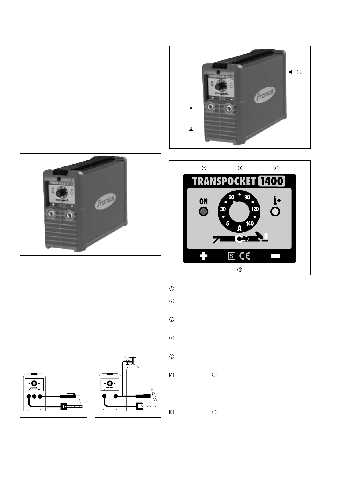
Fig.1 Poste de soudage TP 1400
CONSTRUCTION DE L’APPAREIL
Le TP1400 est de faibles dimensions, mais est construit de manière à
fonctionner avec une fiabilité absolue même dans des conditions d’utilisation
très rudes. Le boîtier en tôle thermopoudrée ainsi que les éléments de
commande et les douilles de raccord avec verrouillage à baïonnette sont
disposés de manière à être protégés par le cadre en matière plastique, et
répondent ainsi aux plus hautes exigences. La courroie pratique permet de
transporter aisément l'appareil dans l'usine ou sur le chantier.
CHAMPS D'APPLICATION
Fig.2 TP 1400 équipé pour le soudage
manuel à l'électrode
Fig.3 TP 1400 équipé pour le soudage
TIG
Fig.5 Eléments de commande et voyants du panneau de commande
Interrupteur principal
Voyant En ordre de marche allumé lorsque le commutateur principal
est mis sur “1”
Régulateur du courant de soudage ... possibilité de régler en continu
le courant de soudage de 5 à 150A
Voyant Dérangement allumé lorsque la température à l'intérieur de
l'appareil est trop élevée
Commutateur Electrode / TIG ... sert à la sélection du procédé de
soudage désiré
Prise de courant à verrouillage à baïonnette ... pour
raccorder
- le câble de l'électrode ou le câble de mise à la masse lors du soudage
manuel à l'électrode (suivant le type d'électrode utilisé)
- le câble de mise à la masse lors du soudage TIG
Prise de courant à verrouillage à baïonnette ... pour
raccorder
- le câble de l'électrode ou le câble de mise à la masse lors du soudage
manuel à l'électrode (suivant le type d'électrode utilisé)
- la torche de soudage lors du soudage TIG (raccordement électrique)
6
Page 27
MISE EN SERVICE DU POSTE DE
SOUDAGE
Attention ! Lire le chapitre "Consignes de sécurité" avant la première
mise en service.
UTILISATION CONFORME A LA DESTINATION
PREVUE
Le poste de soudage est destiné exclusivement au soudage manuel à
l'électrode et au soudage TIG. Toute utilisation à d'autres fins ne saurait être
considérée comme conforme à la destination de l'appareil. Le constructeur
décline toute responsabilité pour les dommages qui résulteraient d'une telle
utilisation.
L'utilisation conforme à l'emploi prévu implique également
- l'observation du manuel de service et
- la réalisation en temps voulu des travaux d'inspection et d'entretien
Attention ! Ne jamais utiliser le poste de soudage pour dégeler des
tuyaux.
CONSIGNES CONCERNANT L'INSTALLATION
Le poste de soudage a été contrôlé en fonction du type de protection IP 23,
ceci signifiant :
- protection contre la pénétration de corps étrangers solides supérieurs à
ø12mm
- protection contre les projections d'eau jusqu’à un angle de 60° par rapport
à la verticale
Comme le poste de soudage répond au degré de protection IP23, il peut être
installé et fonctionner à l'extérieur. Il est toutefois nécessaire de protéger les
éléments électriques incorporés contre l’effet direct de l’humidité.
Attention ! Placer le poste de soudage sur une surface plane et solide
pour éliminer tout risque de renversement. Le renversement d'un
poste de soudage représente un danger de mort.
BRANCHER LA FICHE SECTEUR
Attention ! La fiche secteur doit correspondre à la tension du secteur
et à la consommation de courant du poste de soudage (voir Données
techniques)
Attention ! La protection par fusibles de la ligne d'alimentation doit être
conçue pour la consommation de courant du poste de soudage.
SOUDAGE MANUEL A
L'ELECTRODE
- Suivant le type d'électrode utilisé, brancher le câble de soudage sur la prise
de courant ou et verrouiller en tournant vers la droite.
- Brancher la fiche secteur
- Mettre l'interrupteur principal
Attention! Dès que l'interrupteur principal
l'électrode en baguette est sous tension. Dans ce cas, veiller à ce que
l'électrode n'entre pas en contact avec des pièces conductrices de
courant ou de mise à la terre, telles que pièce à souder, boîtier, etc.
- Le voyant En ordre de marche signale que l'appareil est en ordre de
marche
- Mettre le commutateur Electrode / TIG
- Sélectionner l'intensité de courant sur le régulateur Courant de soudage
- Effectuer le soudage
sur "I"
est mis sur "I" ,
sur position Electrode
Le canal de ventilation est un important dispositif de sécurité. Choisir un
emplacement offrant suffisamment d'espace pour que l'air de refroidissement
puisse entre et sortir librement par les fentes d'air du boîtier de l'appareil. Veiller
à ce que la poussière métallique produite par exemple lors de travaux
d'abrasion ne soit pas aspirée directement par le ventilateur de la soudeuse.
RACCORDEMENT AU SECTEUR
Le poste de soudage est conçu pour la tension secteur indiquée sur la plaque
caractéristique. Pour la protection par fusibles de la ligne d'alimentation, voir
les Données techniques.
Le poste de soudage est conçu en standard pour une tension secteur de 230
V~ (+/- 15 %). En raison de la tolérance de +/- 15 %, l'appareil fonctionne
également sur un secteur de 220 V~.
230 V~
-15%
Fig.6 Plages de tolérance de la tension secteur
Attention! Si l'appareil est conçu pour une tension spéciale, observer
les données techniques figurant sur la plaque caractéristique. La fiche
secteur, le câble d'alimentation ainsi que la protection par fusible
doivent être conçus pour cette tension spéciale.
+15%
265 V~195 V~
SOUDAGE TIG
- Brancher la fiche d'alimentation de la torche de soudage TIG sur la prise
de courant
- Brancher la fiche secteur du câble de mise à la masse sur la prise de
courant et verrouiller en tournant vers la droite
- Equiper la torche (voir manuel de service de la torche de soudage)
- Attacher la pince de mise à la masse sur la pièce à souder
- Fixer le détendeur sur la bouteille de gaz protecteur
- Relier le tuyau de gaz au détendeur
- Ouvrir la valve de la bouteille de gaz
- Mettre le commutateur Electrode / TIG
- Brancher la fiche secteur
- Mettre l'interrupteur principal
Attention! Dès que l'interrupteur principal
l'électrode en tungstène est sous tension. Dans ce cas, veiller à ce
que l'électrode en tungstène n'entre pas en contact avec des pièces
conductrices ou de mise à la terre, telles que pièce à souder, boîtier,
etc.
- Le voyant En ordre de marche signale que l'appareil est en ordre de
marche
- Ouvrir la soupape d'arrêt sur la torche ou appuyer sur le bouton-poussoir
de la torche et régler la quantité de gaz désiré sur le détendeur.
- Sélectionner l'intensité de courant à l'aide du régulateur Courant de
soudage
et verrouiller en tournant vers la droite
sur la position TIG
sur la position "I"
est mis sur "I" ,
FRANÇAIS
7
Page 28
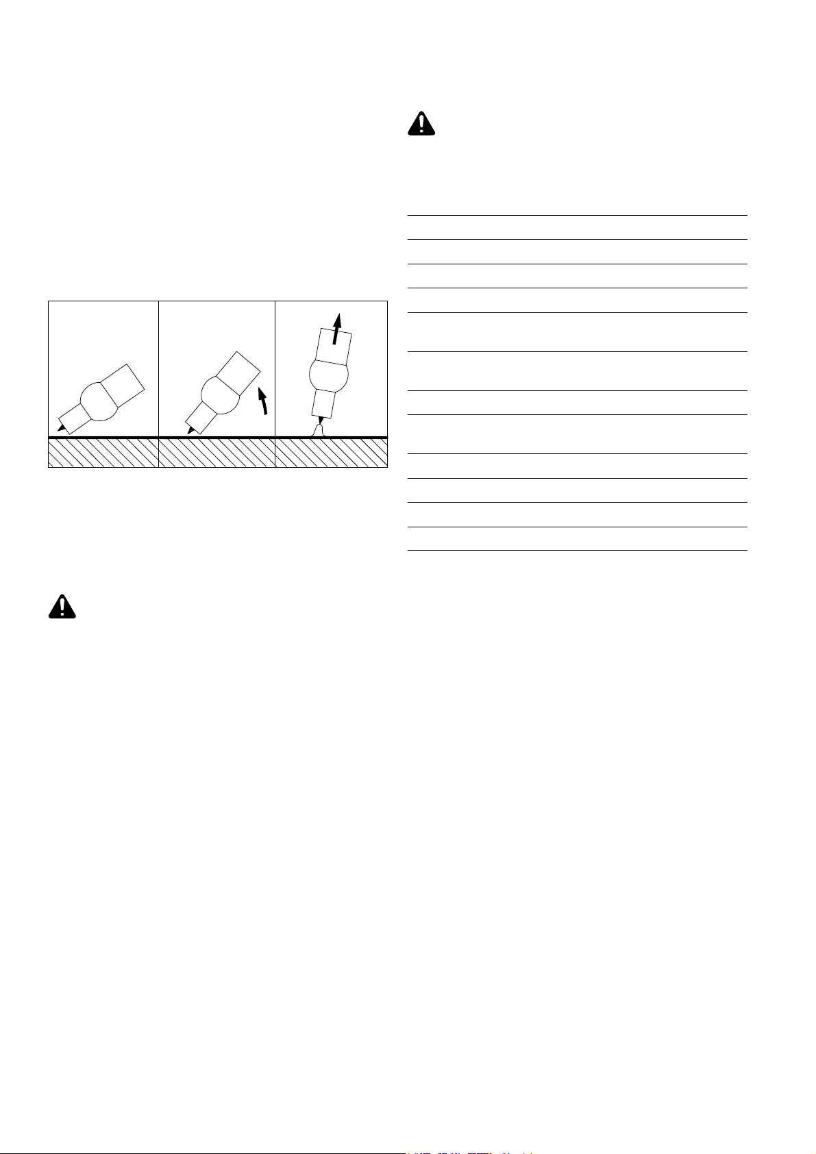
DONNEES TECHNIQUES
- Monter la buse de gaz de la torche sur le point d'amorçage de sorte que
la distance entre la pointe de l'électrode et la pièce à souder soit d'environ
2-3 mm (voir fig. 7a)
- Redresser la torche jusqu'à ce que la pointe de l'électrode touche la pièce
à souder (voir fig. 7b)
- Soulever la torche de soudage et la faire pivoter vers la position normale
- l'arc s'amorce (voir fig. 7c)
- Effectuer le soudage
Nota ! Pour interrompre le soudage, il suffit d'éloigner la torche de soudage
de la pièce à travailler jusqu'à ce que l'arc s'éteigne. La réduction du courant
ne garantit pas le remplissage du cratère final ni sa protection gazeuse.
a) Positionner la buse de
gaz
Fig.7 Positionnement de la torche
b) Amorçage par contact
de la pièce à souder
c) Arc amorcé
Attention! Si l’appareil est conçu pour une tension spéciale, observer
les données techniques figurant sur la plaque caractéristique. La fiche
secteur, le câble d’alimentation ainsi que la protection par fusible
doivent être conçus pour cette tension spéciale.
Tension du secteur 230 V~, 50 - 60 Hz
Protection par fusibles à action retardée 16 A
Cos phi (140 A) 0,99
Rendement (à 100 A) 87 %
Gamme de courant de soudage El - C.C. 5 - 140 A
Courant de soudage 10min/40°C, durée de mise en circuit 35% 140 A
10min/40°C, régime permanent 100 A
Puissance apparente durée de mise en circuit 35 % 6,1 kVA
régime permanent 3,8 kVA
Tension de marche à vide 93 V
Tension de travail électrode 20,2 - 25,6 V
TIG 10,2 - 15,6 V
Protection IP 23
Refroidissement AF
ENTRETIEN
Attention ! Avant d'ouvrir le poste de soudage, le mettre hors circuit,
retirer la fiche secteur et placer un écriteau signalant le danger d'une
remise en circuit - si nécessaire, décharger les condensateurs
électrolytiques.
Pour maintenir le poste de soudage en bon état de fonctionnement pendant des
années, certaines mesures sont nécessaires :
- effectuer une inspection de sécurité aux intervalles indiqués au chapitre
"Consignes de sécurité"
- suivant le lieu d'installation, mais au moins deux fois par an, dévisser les
plaques latérales de l'appareil et purger l'appareil à l'air comprimé sec
réduit. Attention à ne pas diriger l'air comprimé sur des éléments
électroniques à partir d'une faible distance.
- en cas de production importante de poussière, nettoyer le canal de
ventilation .
Classe d'isolation B
S, CE
8
Page 29

PANNES: DIAGNOSTIC ET REMEDES
Attention ! Avant d’ouvrir le poste de soudage, le mettre hors circuit, retirer la fiche secteur et placer un écriteau signalant le danger d’une remise
en circuit - si nécessaire, décharger les condensateurs électrolytiques.
Panne Cause
Interruption de la ligne d'alimentationPas de courant de soudage
Interrupteur principal sur "1", le voyant En
ordre de marche est allumé
Pas de courant de soudage
Interrupteur principal sur "1", le voyant En
ordre de marche n'est pas allumé
Pas de courant de soudage
Interrupteur principal sur "1", le voyant En
ordre de marche est allumé, le voyant Défaut
est allumé
Pas de courant de soudage
Interrupteur principal sur "1", le voyant En
ordre de marche est allumé, le voyant Défaut
clignote
Mauvaises caractéristiques d'amorçage
lors du soudage manuel à l'électrode
Interruption des connexions des câbles de souda-
ge
Mise à la masse insuffisante ou interrompue
Dépassement de la durée de mise en circuit -
surcharge de l'appareil
Le coupe-circuit thermique a déclenché - le ven-
tilateur marche ; défaut du capteur de température
Amenée insuffisante d'air de refroidissement
Bloc de puissance fortement encrassé
Défaut du bloc de puissance
Sélection d'une mauvaise ligne caractéristique
Remède
Contrôler la ligne d'alimentation et la tension
secteur
Vérifier si les câbles sont correctement branchés
Fixer le câble de mise à la masse sur la pièce
Observer la durée de mise en circuit
Attendre la phase de refroidissement ; l'appareil
se remet en service automatiquement après peu
de temps. Sinon : apporter l'appareil au service
après-vente
Assurer une amenée suffisante d'air
Ouvrir l'appareil et purger à l'air comprimé sec
(voir Entretien !)
Déconnecter et reconnecter l'appareil; si le défaut
se représente - apporter l'appareil au service
après-vente
Mettre le commutateur Electrode / TIG sur Electrode (ligne caractéristique EL)
Interruption de l'arc pendant le soudage
Déclenchement du coupe-circuit ou du
coupe-circuit automatique du secteur
Mauvaises caractéristiques de soudage
(forte formation de projections)
Soudage TIG
L'électrode en tungstène fond, inclusions de
tungstène dans le matériau de base pendant la
phase d'amorçage
Tension de combustion trop élevée de l'électrode
(p. ex. électrode utilisée)
Sous-tension du secteur
Protection trop faible du secteur, coupe-circuit ne
convient pas
Fusible de secteur déclenche en marche à vide
Mauvaise polarité de l'électrode
Mise à la masse insuffisante Attacher la pince de mise à la masse directement
Mauvaise polarité de l'électrode en tungstène Raccorder la torche de soudage TIG au pôle
Mauvais gaz protecteur, pas de gaz protecteur
Sélection d'une mauvaise ligne caractéristique
Si possible, utiliser une électrode alternative ou
un poste de soudage à puissance de soudage
plus élevée
Mesurer la tension secteur sur l'appareil, augmenter la section transversale de la ligne
d'alimentation
Assurer un protection convenable du secteur
(voir Données techniques)
Apporter l'appareil au service après-vente
Inverser la polarité de l'électrode, observer les
indications du fabricant
sur la pièce à souder
négatif
Utiliser un gaz protecteur inerte (argon)
Mettre le commutateur Electrode / TIG sur TIG
(ligne caractéristique TIG)
FRANÇAIS
9
Page 30

10
Page 31

Ersatzteilliste
D
Schaltplan
Spare Parts List
GB
Circuit Diagram
Liste de pièces de rechange
F
Schéma de connexions
Lista parti di ricambio
I
Schema
Lista de repuestos
E
Esquema de cableado
Lista de peças sobresselentes
P
Esquema de conexões
Onderdelenlijst
NL
Bedradingsschema
Reservdelsliste
N
Koblingsplan
Seznam náhradních dílù
CZ
schéma zapojení
Список запасных частей
RUS
Электрическая схема
ud_fr_st_tb_00149 012002
Page 32
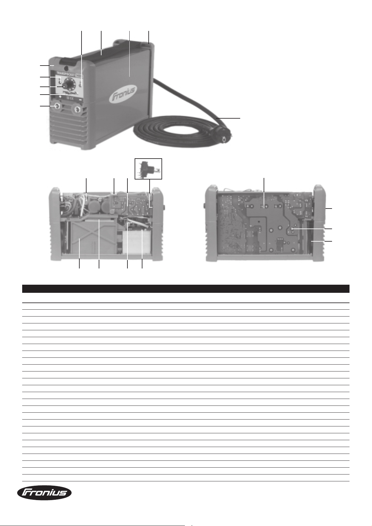
8-10
17 7 3 2
1
18
20
11
5
16
21 22
24
15
6
19
23
12 13
14 4
GÜLTIG AB / APPLICABLE FROM / VALIDES POUR : 09053237
POS. BENENNUNG ARTICLE DENOMINATION
TransPocket 1400 TransPocket 1400 TransPocket 1400 4,075,088
1 VORDERFRONT TP1400 FRONT PANEL TP1400 FACADE TP1400 22,0405,0167
2 RÜCKFRONT TP1400 REAR PANEL TP1400 PANNEAU ARRIERE TP1400 22,0405,0168
3 DRUCK MANTEL TP1400 AM JACKET TP1400 BOITIER TP1400 45,0200,0924
4 THERMOELEMENT TP1400 THERMOSTAT TP1400 THERMOSTAT TP1400 43,0001,1084
5 NETZK. H07RNF 3G2,5 S2 16A 2,5 MAIN-CABLE HO7RNF 3G2.5 S2 16A CABLE ALIMENTATION 3G2.5 43,0004,0519
6 SCHALTWIPP IP 44 GN 16 250 2 ROCKER SWITCH IP44 GR 16 250 2 COMMUTATEUR IP44 GR162502 43,0002,0295
7 TRAGEGURT TP 1400 SHOULDER-STRAP TP1400 BRETELLE TP1400 42,0406,0295
8 DREHKNOPF 16 schw 6mm ACHSE P TURNING KNOB D=16 BLACK 6MM P BOUTON TOURNANT NOIR 42,0406,0099
9 DECKEL 16 schw P COVER D=16 BLACK P CACHE BOUTON NOIR 16 P 42,0406,0108
10 MUTTERABD 16 rot P NUT-COVER 16 RED CAPOT ECROU ROUGE 16 42,0406,0213
11 BUCHSE EB 25 SW14x22 o. Gew. CURRENT SOCKET EB 25 SW14X22 EMBASE COURANT EB 25 SW14X22 42,0001,3070
12 KÜHLKÖRPERHALTERUNG LI. TP1400 HEAT SINK-MOUNTING L. TP1400 MONTAGE PIECE THERMO LI TP1400 22,0405,0170
13 PLANARTRAFO 300 2500VA 45V PLANAR TRANSFORMER 300 2500VA TRANSFORMATEUR PLANE 300 2500VA 43,0030,0021
14 DIOSIL 300 200 200 ISOTO SC SILICON DIODE 300 200 200 ISOT DIODE AU SILICIUM 300 200 200 41,0003,0215
15 PRINT PCF 14 GEPRÜFT PC-BOARD PCF 14 CIRCUIT ELECTRONIQUE PCF 14 4,070,479,Z
16 WIDPOT 25K 20 PC16VM6 300 POTENTIOMETER 25K 20 PC16VM6 POTENTIOMETRE 25K 20 PC16VM6 41,0001,0632
17 LEUCHTDIODE 1.5 Y 5 P LIGTH-EMITTING-DIODE 1.5 Y 5 P DIODE DE SIGNALISATION 41,0006,0053
18 LEUCHTDIODE 1.5 G 5 P LIGTH-EMITTING-DIODE 1,5 G 5 P DIODE DE SIGNALISATION 41,0006,0045
19 GLESIL 1K 35 W S 1 SILICON RECTIFIER 1K 35 W S1 REDRESSEUR AU SILICIUM 1K 35 W 41,0002,0055
20 SCHALTKIPP 5236CD-16 1 SWITCH TOGGLE 5236CD-16 1 INTER A BASCULE 5236CD-16 1 43,0002,0354
21 RELAISPRINT 14 1S 16 RELAY-PC-BOARD 14 1S 16 CIRCUIT ELECTRONIQUE EN RELAIS 43,0008,0129
22 PRINT BSV A PC-BOARD BSV A CIRCUIT ELECTRONIQUE BSV A 4,070,604
23 VENTILATOR M.F.2,4 92x92x25 12 VENTILATOR 2,4 92X92X25,5 VENTILATEUR 2,4 92X92X25,4 43,0006,0153
24 BASISPRINTVERSTEIFUNG TP1400 STRUT HALCOR TP1400 EQUERRE GUIDE HALCOR TP 1400 32,0405,0199
TRANSPOCKET 1400
Ersatzteilliste / Spare parts list / Listes de pièces de rechange / Lista de repuestos / Lista de pecas sobresselentes / Lista dei Ricambi
el_fr_st_eh_00131 022000
1/1
Page 33
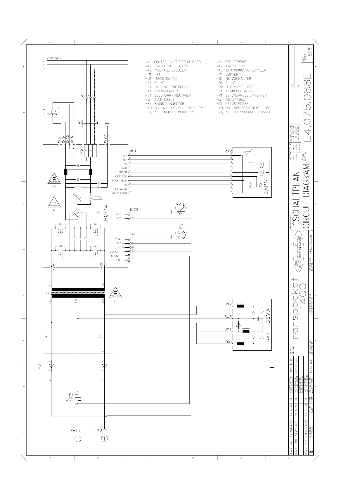
Page 34

Fronius Worldwide - www.fronius.com/addresses
FRONIUS International GmbH
A
4600 Wels, Buxbaumstraße 2
Tel: +43 (0)7242 241-0
Fax: +43 (0)7242 241-3940
E-Mail: [email protected]
http://www.fronius.com
4600 Wels, Buxbaumstraße 2
Tel: +43 (0)7242 241-0
Fax: +43 (0)7242 241-3490
Service: DW 3070, 3400
Ersatzteile: DW 3390
E-Mail: [email protected]
6020 Innsbruck, Amraserstraße 56
Tel: +43 (0)512 343275-0
Fax: +43 (0)512 343275-725
5020 Salzburg, Lieferinger Hauptstr.128
Tel: +43 (0)662 430763
Fax: +43 (0)662 430763-16
1100 Wien, Daumegasse 7,
Tel: +43 (0)1/600 41 02-7410
Fax: +43 (0)1/600 41 02-7490
1100 Wien, Favoritner Gewerbering 25
Tel: +43 (0)7242 241-0
Fax: +43 (0)7242 241-3490
Haberkorn Ulmer GmbH
6961 Wolfurt, Hohe Brücke
Tel: +43 (0)5574 695-0
Fax: +43 (0)5574 2139
http://www.haberkorn.com
Wilhelm Zultner & Co.
8042 Graz, Schmiedlstraße 7
Tel: +43 (0)316 6095-0
Fax: +43 (0)316 6095-80
Service: DW 325, Ersatzteile: DW 335
E-Mail: [email protected]
Wilhelm Zultner & Co.
9020 Klagenfurt, Fallegasse 3
Tel: +43 (0)463 382121-0
Fax: +43 (0)463 382121-40
Service: DW 430, Ersatzteile: DW 431
E-Mail: [email protected]
FRONIUS do Brasil LTDA
BR
Av. Senador Vergueiro, 3260
Vila Tereza, Sao Bernado do Campo - SP
CEP 09600-000, SĂO PAULO
Tel: +55 (0)11 4368-3355
Fax: +55 (0)11 4177-3660
E-Mail: [email protected]
FRONIUS Schweiz AG
CH
8153 Rümlang, Oberglatterstraße 11
Tel: +41 (0)1817 9944
Fax: +41 (0)1817 9955
E-Mail: [email protected]
FRONIUS Česká republika s.r.o.
CZ
381 01 ČESKÝ KRUMLOV, Tovární 170
Tel: +420 380 705 111
Fax: +420 380 711 284
E-Mail: [email protected]
100 00 PRAHA 10, V Olšinách 1022/42
Tel.: +420 272 111 011, 272 742 369
Fax:+420 272 738 145
E-Mail: [email protected]
315 00 PLZEŇ-Božkov, Letkovská 38
Tel: +420 377 183 411
Fax: +420 377 183 419
E-Mail: [email protected]
500 04 HRADEC KRÁLOVÉ,
Pražská 293/12
Tel.: +420 495 070 011
Fax: +420 495 070 019
E-Mail: [email protected]
Under http://www.fronius.com/addresses you will find all addresses of our sales branches and partner firms!
586 01 JIHLAVA, Brněnská 65
CZ
Tel: +420 567 584 911
Fax: +420 567 305 978
E-Mail: [email protected]
709 00 OSTRAVA - Mariánské Hory,
Kollárova 3
Tel: +420 595 693 811
Fax: +420 596 617 223
E-Mail: [email protected]
760 01 ZLÍN
ul. Malá (za čerp. st. ARAL)
Tel: +420 577 311 011
Fax: +420 577 311 019
E-Mail: [email protected]
FRONIUS Deutschland GmbH
D
67661 Kaiserslautern, Liebigstraße 15
Tel: +49 (0)631 35127-0
Fax: +49 (0)631 35127-50
E-Mail: [email protected]
90530 Wendelstein,
Wilhelm-Maisel-Straße 32
Tel: +49 (0)9129 2855-0
Fax: +49 (0)9129 2855-32
51149 Köln, Gremberghoven,
Welserstraße 10 b
Tel: +49 (0)2203 97701-0
Fax: +49 (0)2203 97701-10
57052 Siegen, Alcher Straße 51
Tel: +49 (0)271 37515-0
Fax: +49 (0)271 37515-15
38640 Goslar, Im Schleeke 108
Tel: +49 (0)5321 3413-0
Fax: +49 (0)5321 3413-31
10365 Berlin, Josef-Orlopp-Str. 92-106
Tel: +49 (0)30 557745-0
Fax: +49 (0)30 557745-51
21493 Talkau, Dorfstraße 4
Tel: +49 (0)4156 8120-0
Fax: +49 (0)4156 8120-20
70771 Leinfelden-Echterdingen
(Stuttgart),
Kolumbus-Straße 47
Tel: +49 (0)711 782852-0
Fax: +49 (0)711 782852-10
04328 Leipzig, Riesaer Straße 72-74
Tel: +49 (0)341 27117-0
Fax: +49 (0)341 27117-10
01723 Kesselsdorf (Dresden),
Zum alten Dessauer 13
Tel: +49 (0)35204 7899-0
Fax: +49 (0)35204 7899-10
67753 Hefersweiler, Sonnenstraße 2
Tel: +49 (0)6363 993070
Fax: +49 (0)6363 993072
18059 Rostock, Erich Schlesinger Str. 50
Tel: +49 (0)381 4445802
Fax: +49 (0)381 4445803
81379 München, Gmunder Straße 37a
Tel: +49 (0)89 748476-0
Fax: +49 (0)89 748476-10
83308 Trostberg, Pechleraustraße 7
Tel: +49 (0)8621 8065-0
Fax: +49 (0)8621 8065-10
94491 Hengersberg, Donaustraße 31
Tel: +49 (0)9901 2008-0
Fax: +49 (0)9901 2008-10
FRONIUS France SARL
F
60306 SENLIS CEDEX,
13 avenue Félix Louat - B.P.195
Tél: +33 (0)3 44 63 80 00
Fax: +33 (0)3 44 63 80 01
E-Mail: [email protected]
FRONIUS Norge AS
N
3056 Solbergelva, P.O. BOX 32
Tel: +47 (0)32 232080,
Fax: +47 (0)32 232081
E-Mail: [email protected]
FRONIUS Slovensko s.r.o.
SK
917 01 Trnava, Nitrianská 5
Tel: +421 (0)33 590 7511
Fax: +421 (0)33 590 7599
E-Mail: [email protected]
974 03 Banská Bystrica,
Zvolenská cesta 14
Tel: +421 (0)48 472 0611
Fax: +421 (0)48 472 0699
E-Mail: [email protected]
FRONIUS Ukraine GmbH
UA
07455 Ukraine, Kiewskaya OBL..,
S. Knjashitschi, Browarskogo R-NA
Tel: +38 044 94-62768
Fax: +38 044 94-62767
E-Mail: [email protected]
FRONIUS USA LLC
USA
10503 Citation Drive,
Brighton, Michigan 48116
Tel: +1(0) 810 220-4414
Fax: +1(0) 810 220-4424
E-Mail: [email protected]
+38 044 94-54170
ud_fr_st_so_00082 012006
Page 35
Achtung! Verwenden Sie dieses Schweißgerät im Generatorbetrieb nur an einem geregelten und spannungsstabilisierten Synchrongenerator mit einer Leistung von mindestens 6
kVA an 230 V.
Caution! For generator-powered use, make sure generator is a regulated and voltagestabilized synchronous alternator and welding equipment is powered with 6 kVA minimum
power at 230 V voltage.
Attention! En service par générateur, il faut veiller à ce que le générateur soit un alternateur
synchrone réglé et à tension stabilisée et que l’appareil de soudage soit alimenté en une
puissance minimale de 6 kVA et 230 V.
¡Atención! En servicio generador hay que asegurarse que el generador sea un alternador
sincrónico regulado y estabilizado de tensión y que el equipo de soldadura sea alimentado
en una potencia mínima de 6 kVA y 230 V.
Attenzione! Per farla funzionare tramite generatore, questa saldatrice va collegata soltanto
ad un generatore regolamentato e sincrono con stabilizzazione di tensione e potenza pari
ad almeno 6 kVA per 230 V.
Atenção! Utilize este aparelho de soldagem durante a operação do gerador apenas com
um gerador sincronizado regulado e com tensão estável, com uma potência mínima de 6
kVA a 230 V.
 Loading...