

Page 1

TDTTP3300-RD
Reference Design
Quick Start Guide
TDTTP3000-RD_0.1© 2018 Transphorm Inc. All rights reserved.
+1 805 456 1300
transphormusa.com
TDTTP3300-RD
For evaluation purposes only
Design files and more at
transphormusa.com/tp33kit
02/2018
Page 2
Equipment Needed
gThe TDTTP3300-RD board
gHigh-voltage AC power supply for input
gElectronic/resistive load
• Power range:
350W to 3300W @230V
150W TO 1650W @115V
1 | transphormusa.com transphormusa.com | 6
This reference design is intended as an educational tool for end customers
developing their own bridgeless totem-pole PFC products. The tool kick starts end
product development by providing a digital control design framework. No guarantees
are made for standards compliance.
There are areas of this reference board that have exposed access to hazardous high
voltage levels. Exercise caution to avoid contact with those voltages. Also note that
the reference board may retain high voltage temporarily after input power has been
removed. Exercise caution when handling.
When testing converters on a reference board, ensure adequate cooling. Apply
cooling air with a fan blowing across the converter or across a heatsink attached to
the converter. Monitor the converter temperature to ensure it does not exceed the
maximum rated per the datasheet specification.
See page 5 for operating guidelines.
Cautions and Warnings
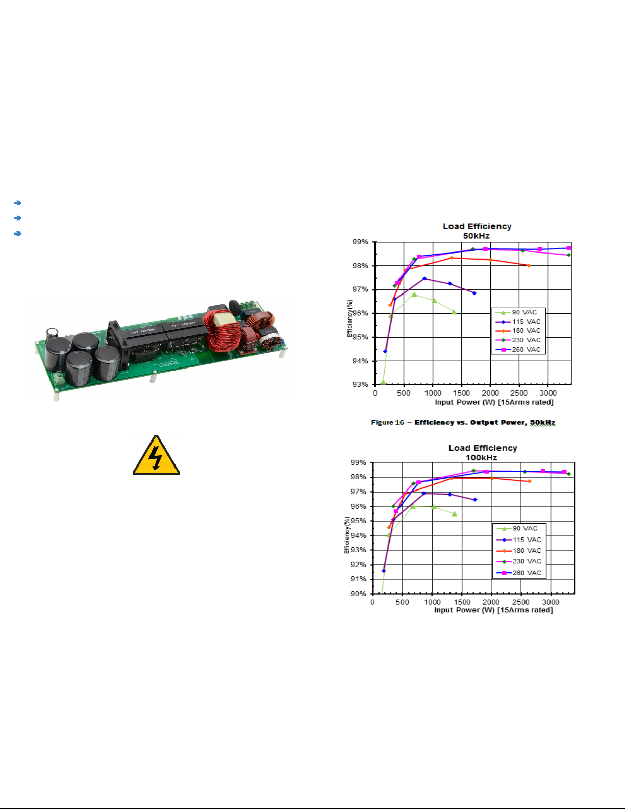
Typical Performance Curves
Page 3
3 | transphormusa.com transphormusa.com | 4
Step 3: Power-down the Board
gSwitch off the high-voltage AC power input
Step 2: Power-up the Board
gConnect an electronic/resistive load to the corresponding marking (CN2).
The requirements for the resistive load are:
• At 115VAC input: 150W to ≤1250W
• At 230VAC input: 350W to ≤3300W
gWith the high-voltage power off, connect the high-voltage AC power input to the
corresponding marking (CN1) on the PCB; N and L (PE: potential ground)
gTurn on the AC power input (85VAC to 265VAC, 50Hz to 60Hz); minimum power
load for turn-on sequence is 150W
gMonitor CN2 output voltage with VDC meter to verify that 385V ±5V is generated
gLoad can be increased when AC supply is on and board is functional
Note:
See page 5 for important operating guidelines
Page 4
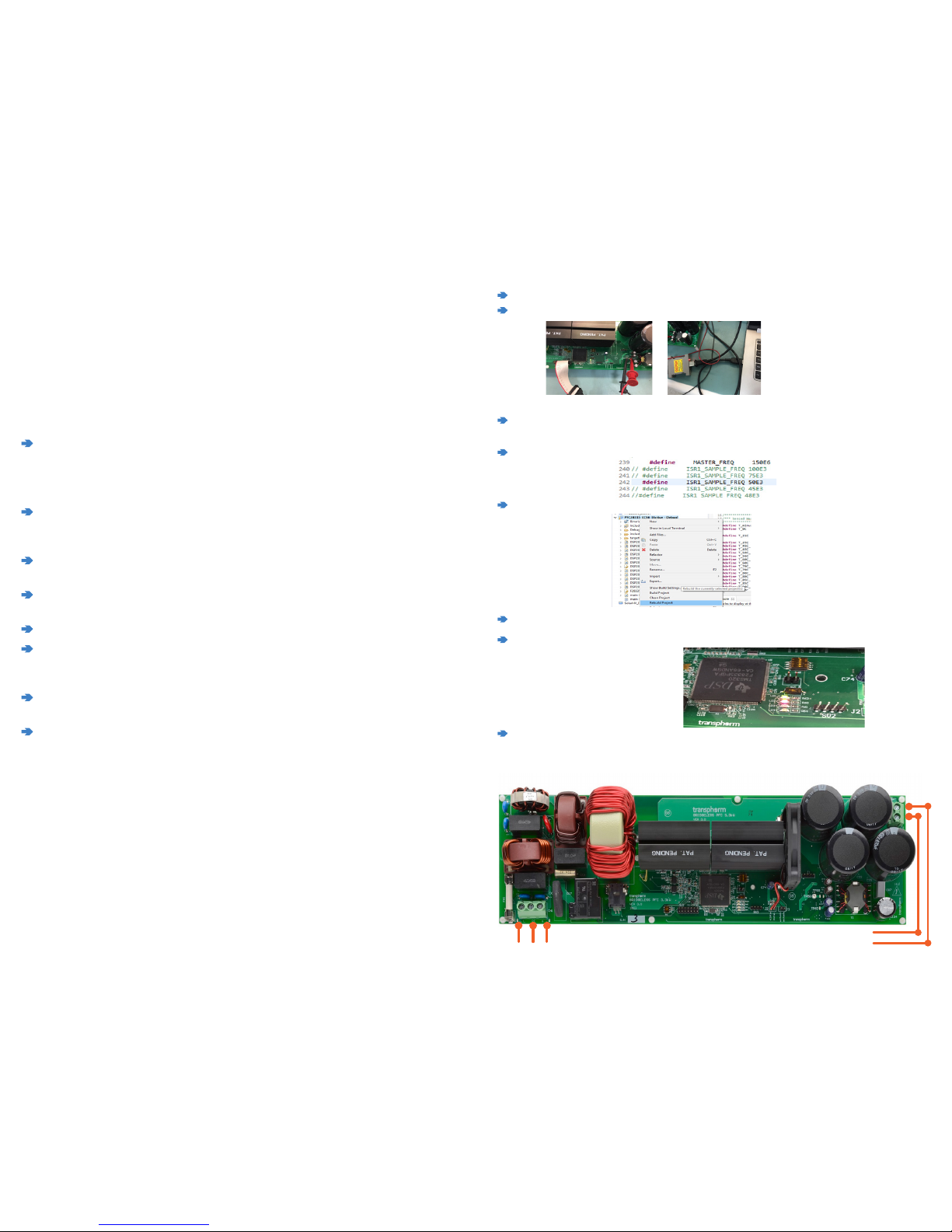
g Connect XDS100-V2 emulator to the PFC board (JTAG) and to computer USB port
gApply 5V auxiliary power(GND-TP58, 5V-TP61)
g Open CCS 6 or CCS 7 - import the 3.3 kW PFC project. Open the main file: main 390Vdc 400uH L
3.3kW_V1.0_dcp_RevVm_cl.c
g At Line 240-243, set the desired switching frequency, (uncomment) desired value between 45E3 and
150E3 (45kHz - 150kHz)
g Select the project in Project explorer window. Right click the project name to rebuild Project, an .out
file will be generated:
g Press F11 or button to download the file to the DSP.
gAfter finishing download, press button to run the code, and the LD2 red light will be shrinking. The
code is downloaded to the DSP successfully.
g Disconnect the auxiliary power connection and Emulator connector for AC power up.
5 | transphormusa.com
transphormusa.com | 2
Step 1: Connect the Board
#1 Connect high-voltage
AC power supply
L PE N
#2 Connect electronic/resistive
load (150W - 3300W)
+ –
Important Operating Guidelines
The TDTTP3300-RD is intended as an educational tool for end customers developing
their own bridgeless totem-pole PFC products. The reference board kick starts end
product development by providing a digital control design framework. The reference
board is not intended to be a finished product in terms of all required design testing
and/or manufacturing-related protective considerations, including but not limited
to product safety and environmental measures typically found in end products that
incorporate such semiconductor components or circuit boards. Additionally, the
reference board does not include all protection features found in commercial power
supplies. Additional warnings to keep in mind:
gAn isolated AC source should be used as input.
Float the oscilloscope by using an isolated oscilloscope or by
disabling the PE (Protective Earth) pin in the power plug. Float the current probe
power supply (if any) by disabling the PE pin in the power plug.
gUse a resistive load only. The totem-pole PFC kit can work at zero load with burst
mode and the output voltage will be swinging between 375V and 385V during
burst mode.
gThe reference board is not fully-tested at large load steps. DO NOT apply a very
large step in the load (>1000W) when it is running.
gDO NOT manually probe the waveforms when the board is running. Set up
probing before powering up the demo board.
gDO NOT touch any part of the evaluation board when it is running.
gIf the evaluation circuit goes into protection mode it will work as a diode bridge by
shutting down all PWM functions. Recycle the bias power supply to reset the DSP
and exit protection mode.
gTo get clean VGS of the low side GaN FET, it is not recommended to measure the
VDS at the same time.
gIt is not recommended to use a passive voltage probe for VDS and VGS
measurements while simultaneously using a differential voltage probe for VIN
measurements, unless the differential probe has very good dV/dt immunity.
Step 0: Before Power Up
 Loading...