

Transonic TC2380LCD Instruction Manual
Model:TC2380LCD

Contents
1 Introduction...................................................................................... 2-5
2 Installation...................................................................................... 6-10
3 Operation....................................................................................... 11-14
4 Trouble Shooting............................................................................ .....15
5 Remote Controller.......................................................................... 16-17
6 DVD MENU....................................................................................18-36
7
Warranty Card.........................................................................................37
-1-
INTRODUCTION
Thank you very much for purchasing this TV. To enjoy your product from the very
beginning, read this manual carefully and keep it handy for easy reference.
INSTALLATION
Locate the TV in the room where light does not strike the screen .
directly
Total darkness or a reflection on the picture screen can cause eyestrain. Soft and indirect
lighting is recommended for comfortable viewing.
Allow enough space between the TV and the wall to permit ventilation.
Avoid excessively warm locations to prevent possible damage to the cabinet or premature
component failure.
This TV can be connected to AC 230-240 Volts. 50 Hz. Never connect to a DC supply
or any other power supply.
Do not cover the ventilation openings when using theTV.
CAUTION
Never tamper with any components inside the TV, or any other adjustment controls not
mentioned in this manual. All LCD-TVs are high voltage instruments. When you clean
up dust or water drops on the LCD PANEL or CABINET, the power cord should be
pulled out from the receptacle, then wipe the TV with a dry soft cloth. During thunder
and lighting, unplug the power cord and antenna cord to prevent damage to your TV.
All repairs to this TV should only be performed by qualified TV service personnel.
-2-
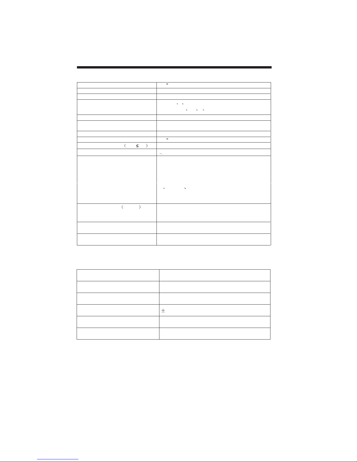
Specification
INTRODUCTION
Viewing Pic ture Size(diagonal)
Resolution 1366x768
Aspect Ratio 16:9
stem
TV Sy
Video Signal Sys tem PAL/NTSC/SE C AM
Receiving Range
npu t Power Voltage AC 230 V-240 V 50 Hz
I
consumption
Power
Audio Output Power THD 7%
Nonactive Pixel
Signal Input
Horizontal definition
Size 800(W)x560(H)x1070(D)
Net weight 19.3kg
Note:The LCD panel is very high technology product, giving you finely detailed picture .
Occasionally a few non-active pixels may appear on the screen an fixed point of colour
this does not affect the performance of you product.
DVD specification
TV line
32
PAL-B/G I D/K
SECA M- B/G
44.75MHz-867.25MHz
170 W
32
2x 8W
<
3
Analog RGB(PC)x1
High-Definition Multimedia Interface(HDMI)x1
Video Inputx1
Super Videox1
Audio Inputx3
Cb (Pb ) Cr (P r)x1
Y
SCA RTx2
Composite Video in pu t >=350
Super Video Input >=400
Y Cb(Pb ) Cr(Pr ) >=400
D/K L LL
Full SCARTx1(Scart CVBS+RGB)
Half SCARTx1(SCART CVBS)
Compatible discs DVD/MPEG-4/SVCD/VCD/CD/MP3/KODAK/JPEG
Resolution ratio 500 lines
Video S/N ratio 65dB
Frequency response(20HZ-20KHZ) 2dB
Video D/A Conversion Rate 10Mbit
Audio D/A Conversion Rate 24bit/192kHz
Note:Designandspecificationsaresubjecttochangewithoutpriornoticeforthepunposeof
performanceimprovement
-3-
Accessories
Accessories
INTRODUCTION
AC Power Cord.........................
Remote Control.........................
User s Manual ........................
Battery(AAA).......................... 2
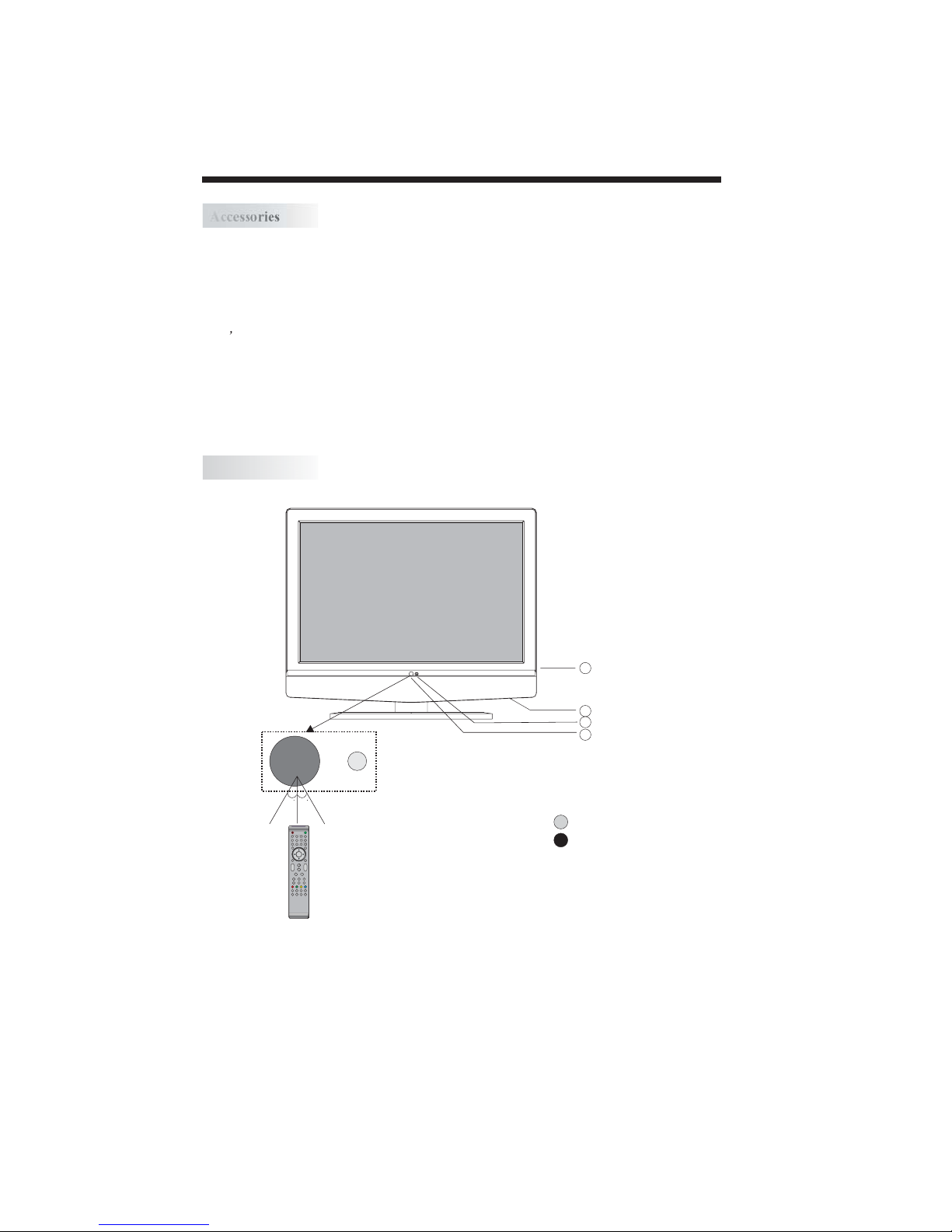
Front panel
1
1
1
3
30 30
4
2
1
1: Remote control sensor.
2: Indicator LED: GREEN POWER ON.
ENTER
3: Key board(see next page).
RED STAND BY.
4: AC power switch.
-4-
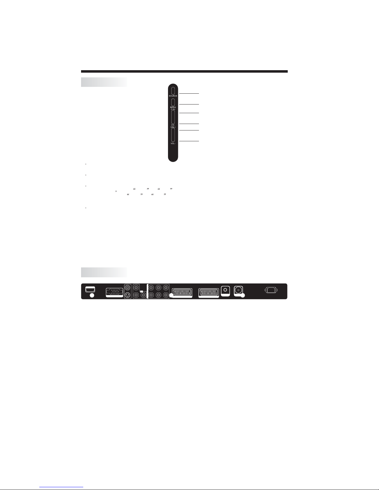
KEYBOARD
S-VIDEO
AV-VIDEO
YLLL
Y.Pb.P r
INPUT
Pb Pr
RRR
PC Y.Pb.Pr AV
AUDIO INPUT
AC-INPUT
100-240V~ 50/60Hz
ANT
SCART1(FULL)
SCART2(HALF)
VGA INPUT
HDMI INPUT
EARPHONE
SOURCE
MENU
CH+
CH-
VOL+
VOL-
1 SOURCE
Display the input source menu.
2MENU
To display main MENU.
3 CH+/CH-
In TV mode press CH+ or CH- to change the channel up and down.
In MENU,press CH+ or CH- to select items in MENU.
In standby mode, it can turn on the TV.
4 VOL+/VOL-
Adjust sound level.
In MENU,adjust the item that you selected.
INSTALLATION
REAR TERMINALS
AV-VIDEO
HDMI INPUT
VGA INPUT
All the terminals are(from left to right):
HDMI, VGA , ,YPbPr,PCAUDIO,
FULL AC POWER.
CVBS/S-VIDEO YPbPr AUDIO,AVAUDIO
SCART1, HALF SCART2 , HEADPHONE,ANTENNA,
Note: CVBS and S-VIDEO share one audio channel.
SCART1(Full) is a scart with CVBS and RGB input.
SCART2(Half) is a scart with CVBS input only
.
YLLL
Y.Pb.P r
PC Y.Pb.Pr AV
INPUT
Pb Pr
AUDIO INPUT
RRR
S-VIDEO
SCART1(FULL)
ANT
EARPHONE
SCART2(HALF)
-5-
AC-INPUT
100-240V~ 50/60Hz
INSTALLATION
-6-
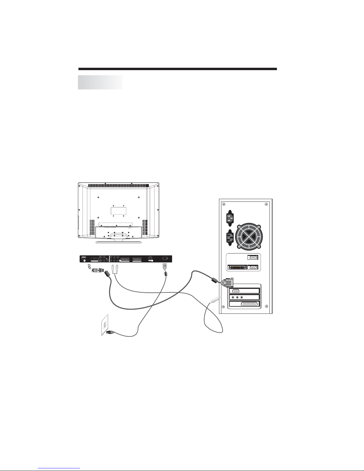
PC
S-VIDEO
AV-VIDEO
YLLL
Y.Pb.Pr
INPUT
Pb Pr
RRR
PC Y.Pb.Pr AV
AUDIOINPUT
AC-INPUT
100-240V~50/60Hz
ANT
SCART1(FULL) SCART2(HALF)
VGAINPUT
HDMIINPUT
Be sure both the TV and computer are set to Power off.
1.Connect VGA and audio cable.
2.Connect the power cord.
3.Power on the TV, switch to PC mode.
4.Power on the PC.
This sequence is very important.
INSTALLATION
8
AV-VIDEO
VGAINPUT
YLLL
Y.Pb.Pr
INPUT
AUDIOINPUT
S-VIDEO
Pb Pr
PC Y.Pb.Pr AV
RRR
SCART1(FULL) SCART2(HALF)
AC-INPUT
ANT
100-240V~50/60Hz
HDMIINPUT
-7-

PC
PRESET MODE(recommended resolution is 1366*768@60Hz)
INSTALLATION
RESOLUTION
1
2
3
4
5
6
7
8
9
10
11
12
720*400
640*480
640*480
640*480
800*600
800*600
800*600
800*600
1024*768
1024*768
1024*768
1280*1024
V.Freq.(Hz) H.Freq.(KHz)
70
60
72
75
56
60
75
72
60
70
75
60
31.47
31.47
37.86
37.50
35.156
37.88
46.88
48.08
48.36
56.48
60.02
63.98
13
1280*1024
75
-8-
80.00
INSTALLATION
S-VIDEO
AV-VIDEO
YLLL
Y.Pb.Pr
INPUT
Pb Pr
RRR
PC Y.Pb.Pr AV
AUDIOINPUT
AC-INPUT
100-240V~50/60Hz
ANT
SCART1(FULL)
SCART2(HALF)
VGAINPUTVGAINPUT
HDMIINPUT
EARPHONE
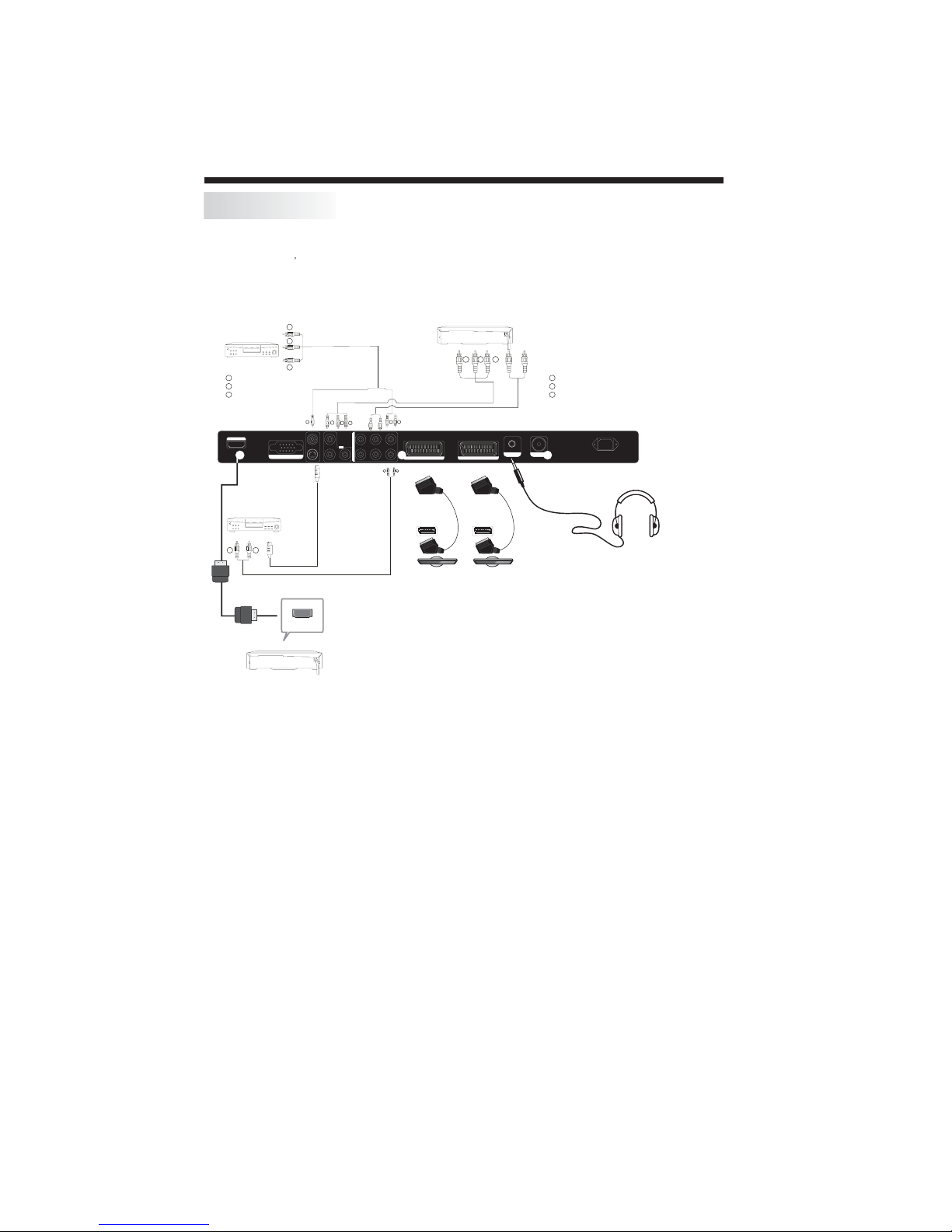
AV EQUIPMENT
This TV provides one group of AV ,S-Video,one HDMI, one group of (YPbPr) and two SCART(half
scart and full scart) sockets for convenient connection to VCR,DVD or other video equipment. Please
refer to the owner s manual for the equipment to be connected as well.
You can use the input terminals on rear of the TV as follows.
with
terminal
VIDEOEQUIPMENT
Y
Yellow(video)
W
White(audol L,mono input)
Red(audio R)
R
HDMIINPUT
with S-v ideo
terminal
VIDEOEQUIPMENT
W R
Toaudio
R
outputs
W
Tovideo
Y
output
Y W R
AV-VIDEO
VGAINPUT
S-VIDEO
ToS-VIDEO
output
G
R
B
YLLL
Y.Pb.Pr
PC Y.Pb.Pr AV
INPUT
AUDIOINPUT
RRR
Pb Pr
W R
VIDEO EQUIPMENT with YPbPr
SCART1(FULL)
SCART
GBR
SCART2(HALF)
SCART
R
Rr
G
Y
Pb
B
ANT
EARPHONE
AC-INPUT
100-240V~50/60Hz
Toaudio outputs
HDMI
It can be connected to the following appliances: VCR, multi-disc player, DVD, camcorder, video game
or stereo system, etc.....
YPbPr and HDMI can support these video fomats:480i,576i,480p,576p,720p,1080i.
NOTE:
Headphone
When headphone is connected, the speakers of the TV set will be disconnected.The
VOLUME -/+ keys are used to adjust the volume level. The headphone impedance
must be between 32 to 600 Ohm.Ohm
-9-
 Loading...