

Transmitter Solutions GEM-300, GEM-600, GEM-800, GEM-D800, GEM-1200 Installation Manual
...Page 1
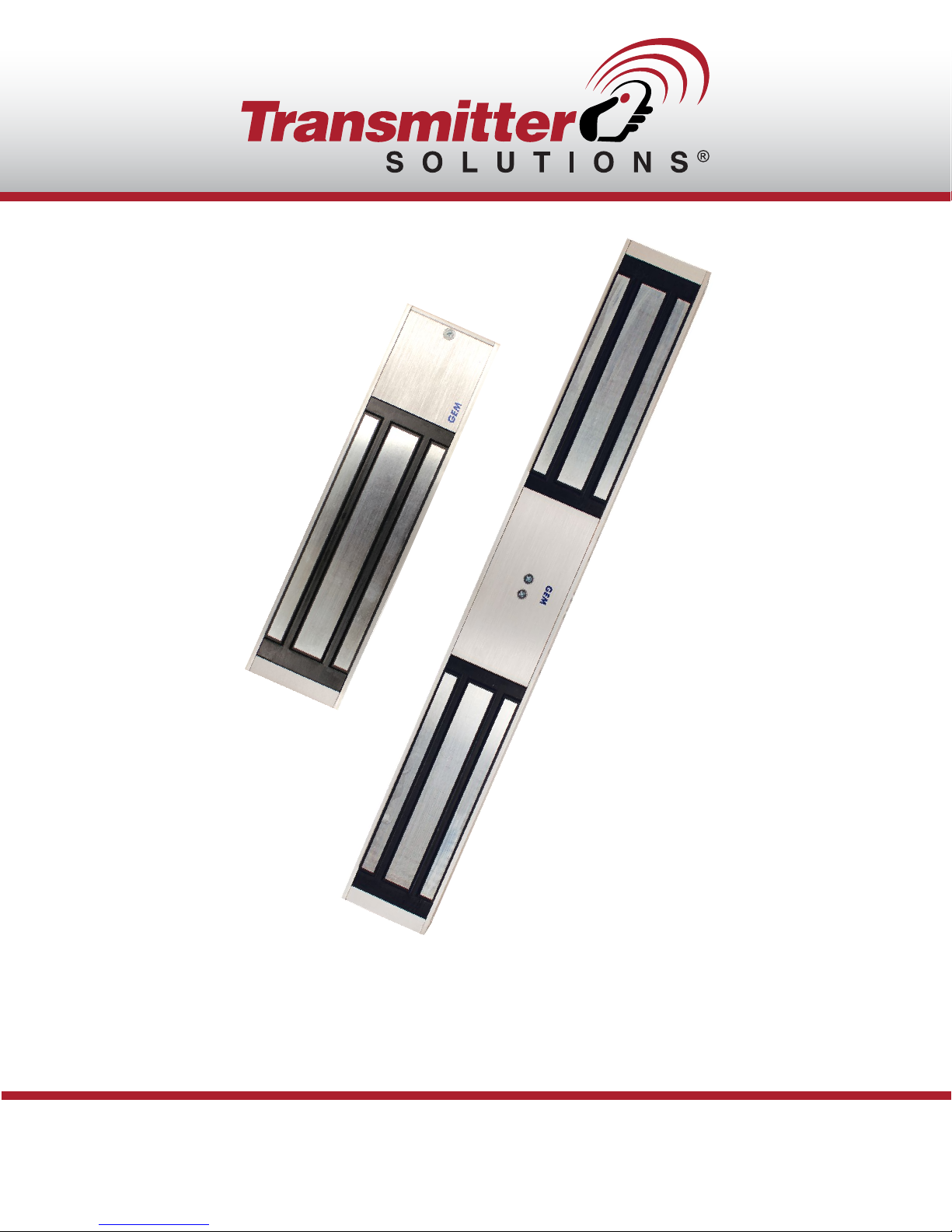
STANDARD / DOUBLE STANDARD
MAGNETIC LOCK
INSTALLATION MANUAL
Page 2
INDOOR ELECTROMAGNETIC LOCK SERIES
Spec/Model
Holding Force
Voltage Input
Current Draw
GEM-300
300lbs (136kg)
12/24VDC
500mA/12VDC
250mA/24VDC
GEM-600
600lbs (272kg)
12/24VDC
500mA/12VDC
250mA/24VDC
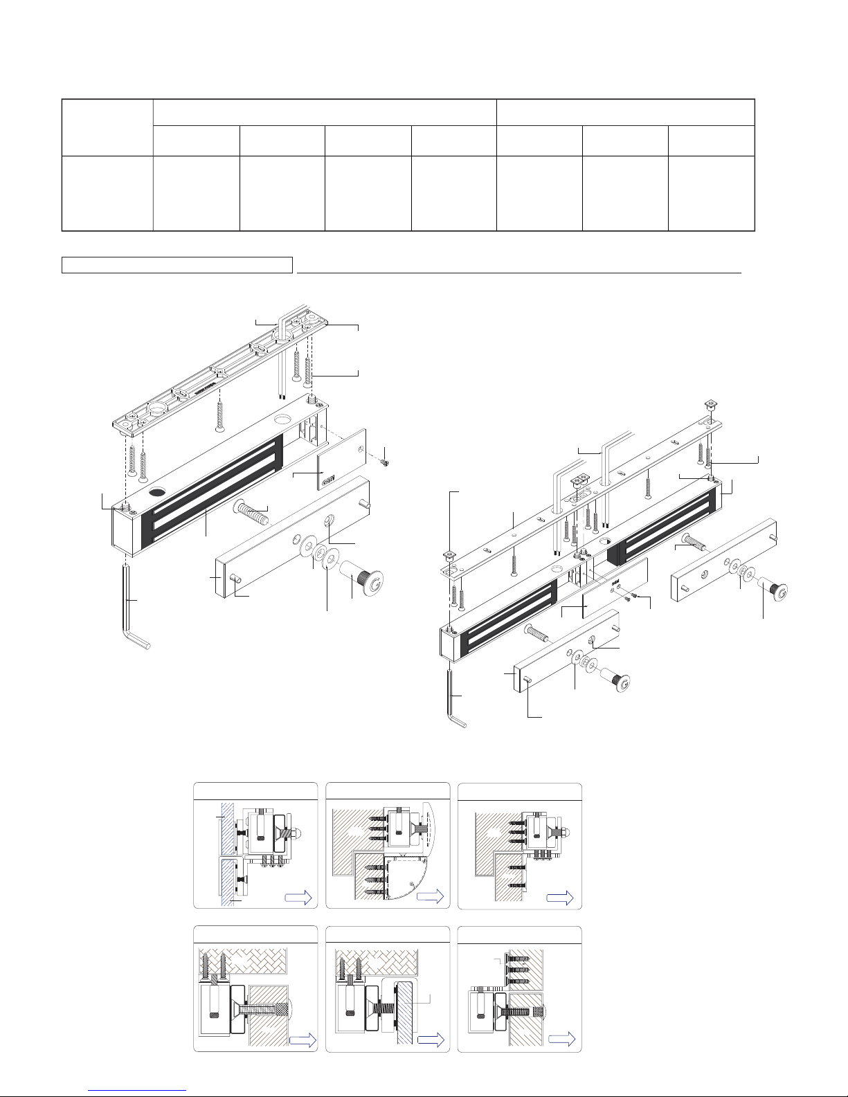
Basic Installation Concept & Accessories
Cable Wire
Fixing Screw
x2
Cover Plate
Armature
Screw
Single Door
GEM-800
800lbs (363kg)
12/24VDC
500mA/12VDC
250mA/24VDC
12/24 VDC
Power
Mounting Plate
Self-tapping
Screw x5
Cover
Screw
GEM-1200
1200lbs (545kg)
12/24VDC
500mA/12VDC
250mA/24VDC
Anti-tamper Nut x4
Double Door
GEM-D600 GEM-D800 GEM-D1200
600lbs (272kg)x2
12/24VDC
500mA/12VDC x2
250mA/24VDC x2
Mounting Plate
800lbs (363kg)x2
12/24VDC
500mA/12VDC x2
250mA/24VDC x2
Cable Wire
12/24 VDC
Power
Fixing Screw
x4
1200lbs (545kg)x2
12/24VDC
500mA/12VDC x2
250mA/24VDC x2
Self-tapping
Screw x10
Electromagnet x2
Armature Plate
Allen Wrench
Electromagnet
Glass Frame & Glass Door
Glass
Frame
Guide Pin x2
UBK Bracket For
EM Lock
Glass
Door
Standard Installation
For Outswing Door
Door
Frame
Rubber
Washer
Metal Washer
x2
Inswing
Anti Residual
Magnetism
Part
Sexnut Bolt
EM Bracket For
Inswing Door With Cover
Door
Frame
EM Lock
Door
U Bracket For Glass Door
Door
Frame
Inswing
Glass
Door
Cover Plate
Armature
Plate x2
Allen Wrench
LZ Bracket For Inswing Door
Door
Frame
EM Lock
Door
L Bracket For Outswing Door
Door
Frame
Metal Washer x4
Guide Pin x4
Inswing
Armature
Screw x2
Cover Screw x2
Anti Residual
Magnetism
Part x2
Rubber
Washer x2
Sexnut Bolt
x2
EM Lock
Door
Outswing
EM Lock
Outswing
EM Lock
Door
Outswing
Page 3
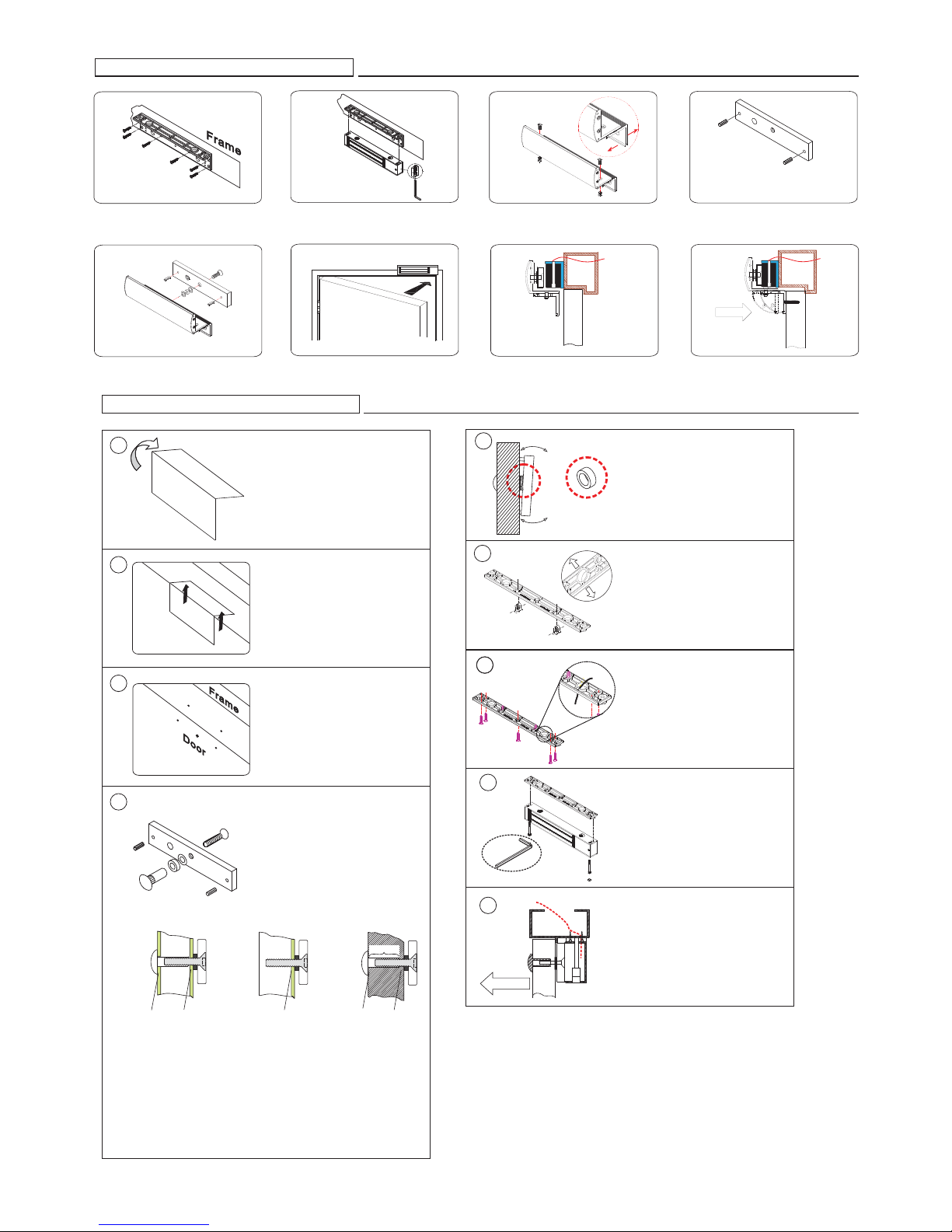
LZ bracket for Inswing doors
1
Find a mounting loca tio n o n th e
door frame for the L bracket. Make
sure that the door is still closeable.
5
Fasten the armature plate to the Z
bracket (Must add rubber washer)
Standard Installation
1
Template
2
2
Use the fixing bolt to tighten the
electromagnetic lock on L bracket
6
Close the door and connect the
power.
Fold the mounting template 90°
Place the template to the proper
position of the door and frame.
Mark the hole positions of the
template on the door and frame.
3
Assemble the Z bracket, and make
sure that the position of the Z bracket
is adjustab le.
7
After the m aglock attracts the
armature plate, adjust the Z
bracket t o fit the door.
Power
Outdoor
4
Insert the guide pins into the
armature plate.
Finish
Outdoor
Fasten the Z bracket to the door
Power
5
The rubber washer makes the
Rubber Washer
surface of the armature plate
adjustable in order to completely
fit the surface of magnetic lock.
6
Fasten the mounting plate with
the mounting screws. The position
of the mounting plate should be
adjustable.
3
Drill the holes according to the
marks.
4
Armature Plate
Please install the armature plate
as illustrated here. (Dimensions
of the holes depend on the door
types illustrated below.)
Hollow Metal Door
Outdoor
12.7mm 8mm
Drill a Ø8mm ho le thr ough
door, on closing side.Enlarge
to Ø12.7mm by a sexnut blot
on the opening side.
Recommendation:
For Micro EM-locks (300 LBS), maximum thickness of door is 4 4 mm.
For Mini EM-locks (600 LBS), maximum thickness of door is 5 0 mm.
For Midi EM-locks (800 LBS), maximum thickness of door is 4 8 mm.
For Maxi EM-locks (1200 LBS), maximum thickness of door is 4 6 mm.
Reinforced Door
Outdoor
6.8mm for M8-1.25 thread
Drill a Ø6.8m m hole
and tap on closing side
a M8x12.5 thread.
Outdoor
12.7mm 8mm
Drill a Ø8mm hole through
door on closing side.Enlarge
to Ø12.7mm by a sexnut
blot on the opening side.
The depth is 36mm.
Solid Door
36mm
77
8
Allen wrench
Power
9
Outswing
Fix the mounting plate on the
door with mounting screws
Use the Allen wrench and fixing
bolts to tighten the electromagnetic
lock to mounting plate
Connect the power and test the
unit.
Page 4
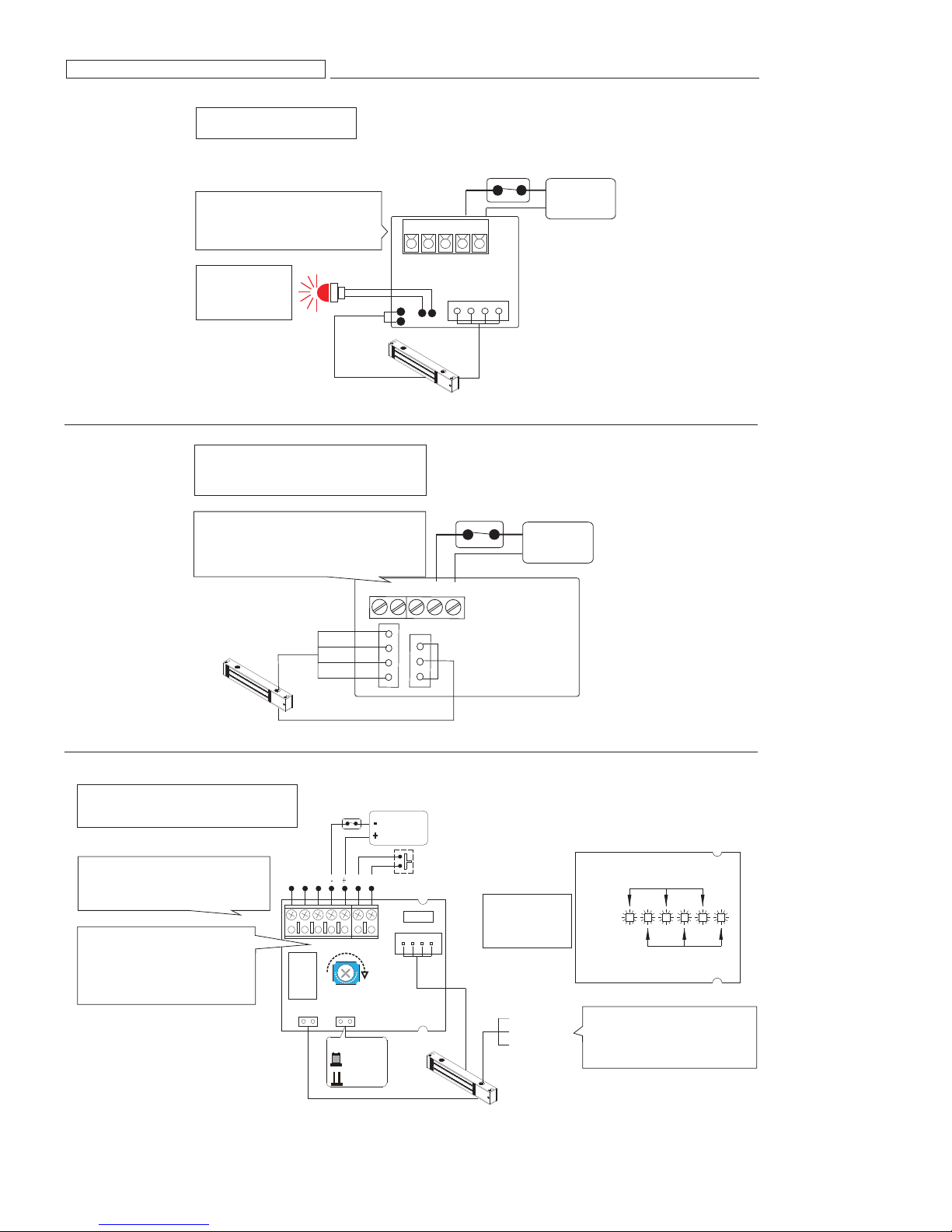
Connecting Diagram
Model:GEM-300M
Bond sensor output
N.C. contact output: open status
N.O. contact output: locked status
LED indicator
GREEN: Open
RED : Locked
NO LED: No power
Sensor Input
Models:
GEM-300, GEM-600, GEM-800, GEM-1200
GEM-D600, GEM-D800, GEM-D1200
Bond sensor output
N.C. contact output: open status
N.O. contact output: locked status
COM.
N.C.
SPDT relay
0.5A/ 125
1A
/24VDC
Control Device N.C. contact or
Access Relay
N.O.
Pow re
VAC
I tupn
Power Input
Control Device N.C. contact or
Access Relay
12 or 24V
Auto
switchable
12 or 24V
Auto
switchable
Mag Power Input
Models:
GEM-800MDS-TD-LD, GEM-800MTD-LD
GEM-1200MDS-TD-LD, GEM-1200MTD-LD
Bond sensor output
N.C. contact output: open status
N.O. contact output: locked status
Relock time delay (Optional)
Ensures the automatic lock mode
works after the door is closed properly
and it can be adjusted from 1 to 80
seconds.
Models: TD series
.C.N
.O.N
MOC
Timer Adjustment
0.5A/125VAC
SPDT relay
1A/24VDC
tupnI rosneS kcoL
N.O.
COM.
N.C.
Sensor Input
Control Device N.C. contact or
Access Relay
12 or 24V
Auto
switchable
Control Device N.C. contact or
TSR
Access Relay
TSR
tupnI rewoP
sdnoces 08~1
JP Setting
Green LED (Default)
Red LED
Sensor in
LED indicator
GREEN: Open
RED: Locked
NO LED: No power
Orange: N.O.
White: Com
Brown: N.C.
(PCB back)
DEL neerG
DEL deR
Door Status Sensor (optional)
Door Status Sensor indicates the
door is in an open or closed status.
Models: DS series
Page 5
Connecting Diagram
Orange: N.O.
White: Com
Brown: N.C.
Door Status Sensor (optional)
Door Status Sensor indicates the door is in an open
or closed status.
Models:
GEM-600MDS, GEM-800MDS, GEM-1200MDS
GEM-D600MDS, GEM-D800MDS, GEM-D1200MDS
Bond sensor output
N.C. contact output: open status
N.O. contact output: locked status
Models:
GEM-600M, GEM-800M, GEM-1200M
GEM-D600M, GEM-D800M, GEM-D1200M
N.O.
COM.
N.C.
LED indicator
GREEN: Open
RED : Locked
NO LED: No power
Sensor Input
Timer Adjustment
Relock time delay (Optional)
Ensures the automatic lock mode works after the door is
closed properly and it can be adjusted from 1 to 80 seconds.
GEM-600M, GEM-800M, GEM-1200M
GEM-D600M, GEM-D800M, GEM-D1200M
Control Device N.C. contact or
Access Relay
12 or 24V
Auto
switchable
Mag Power Input
1~80 seconds
Trouble Shooting
Problem Possible Cause Solution
Door does not lock
Low holding force
Sensor output is not functioning
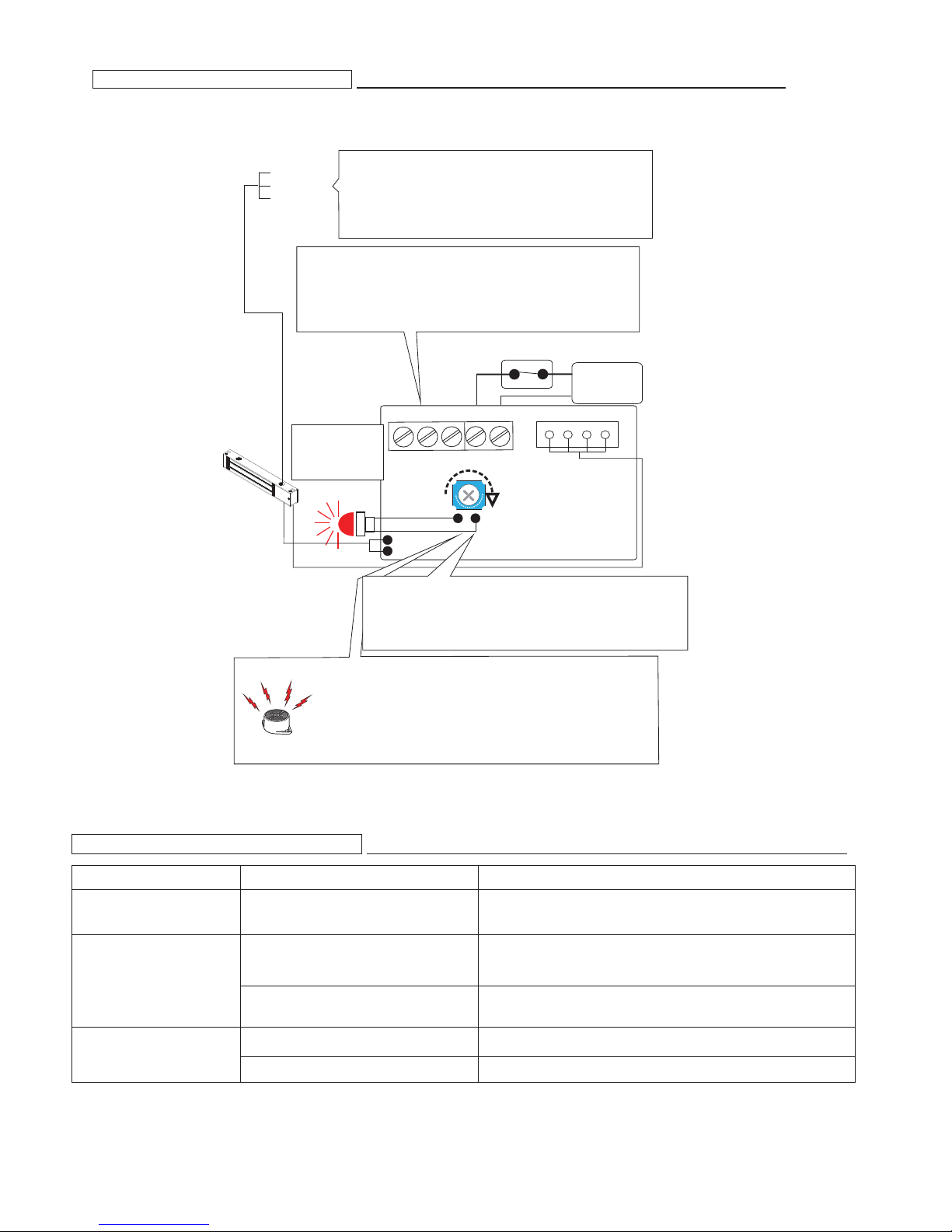
Buzzer Alarm (on the reverse)
Door Held Open Alarm is an auditory feedback for users.
Alarm sounds when the door is not closed for over a specified
time limit. VR timer (Timer Adjustment) is adjustable from
1 to 80 seconds.
(Available for GEM-800MBZ & GEM-1200MBZ)
GEM-D800MBZ & GEM-D1200MBZ)
No power
Poor contact between electromagnet and
armature plate
Low voltage or incorrect voltage setting
A secondary diode was installed across
the electromagnetic lock
Misalignment between the armature plate
and electromagnetic lock
Make sure the wires are connected properly
Check that the power supply is connected and works properly
Make sure the lock switch is wired correctly (N.C.)
Make sure if the armature plate is deformed
Make sure if the rubber washer was used between magnet lock and armature plate
Make sure the contact surfaces of the electromagnet and armature plate are clean
and free from dust
Ensure the electromagnet lock is set for the correct voltage.
Check for proper voltage at the electromagnetic locks input. If low, determine i f the
correct wire gauge is being used to prevent excessive voltage drop.
Remove any diode installed across the magnet for "spike"
suppression. (The magnet is fitted with a metal oxide varistor to prevent back EMF)
Make sure the armature plate and electromagnetic lock are aligned correctly
Page 6

H
WARRANTY:
The warranty period of Transmitter Solutions magnetic locks is twenty-four (24) months. This warranty shall begin on the date the keypad is
manufactured. During the warranty period, the product will be repaired or replaced (at the sole discretion of Transmitter Solutions) if the
product does not operate correctly due to a defective component. This warranty does not extend to (a) the case, which can be damaged
by conditions outside the control of Transmitter Solutions, or (b) battery life. This warranty is further limited by the following disclaimer of
warranty and liability:
EXCEPT AS SET FORTH ABOVE, TRANSMITTER SOLUTIONS MAKES NO WARRANTIES REGARDING THE GOODS, EXPRESS OR
IMPLIED, INCLUDING WARRANTY OF MERCHANTABILITY OR WARRANTY OF FITNESS FOR A PARTICULAR PURPOSE. BUYER MAKES
NO RELIANCE ON ANY REPRESENTATION OF TRANSMITTER SOLUTIONS, EXPRESS OR IMPLIED, WITH REGARD TO THE GOODS
AND ACCEPTS THEM “AS-IS/WHERE-IS”. TRANSMITTER SOLUTIONS SELLS THE GOODS TO BUYER ON CONDITION THAT
TRANSMITTER SOLUTIONS WILL HAVE NO LIABILITY OF ANY KIND AS A RESULT OF THE SALE. BUYER AGREES THAT TRANSMITTER
SOLUTIONS SHALL HAVE NO LIABILITY FOR DAMAGES OF ANY KIND, WHETHER DIRECT, INCIDENTAL OR CONSEQUENTIAL
DAMAGES, INCLUDING INJURIES TO PERSONS OR PROPERTY, TO BUYER, ITS EMPLOYEES OR AGENTS, AS A RESULT OF THE SALE.
BUYER ALSO AGREES TO HOLD TRANSMITTER SOLUTIONS HARMLESS FROM ANY CLAIMS BUYER, OR ANY THIRD PARTY, MAY
HAVE AS A RESULT OF BUYER’S USE OR DISPOSAL OF THE GOODS. BUYER HAS READ THIS DISCLAIMER AND AGREES WITH ITS
TERMS IN CONSIDERATION OF RECEIVING THE GOODS.
 Loading...