

Page 1
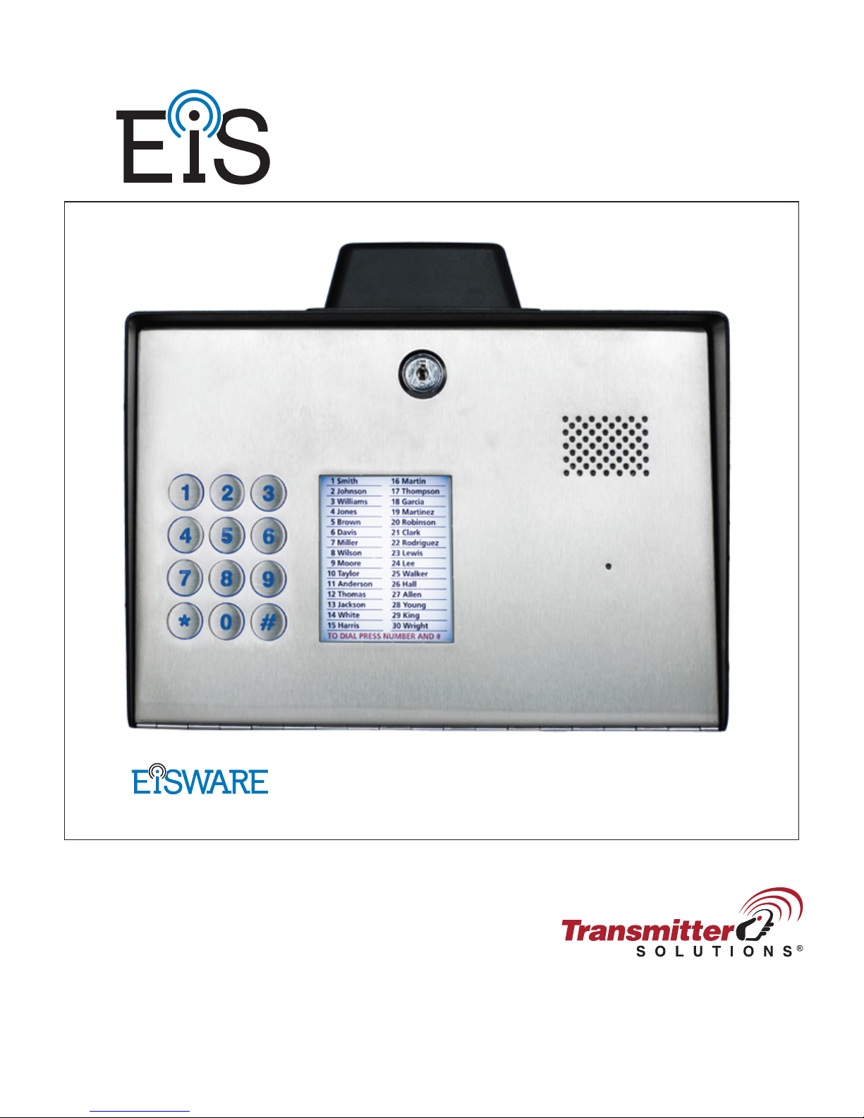
: DOOR ENTRY UNIT
EIS-40
Programming Software
USER MANUAL
v.1.4.20161115
Page 2

EIS-LCD,!EIS-40!
USER!MANUAL!
Page%1%
Page 3

EIS-LCD,!EIS-40!
USER!MANUAL!
Page%2%
Contents
1! FOR YOUR SAFETY.................................................................................................................................................4!
2! INTRODUCTION ....................................................................................................................................................... 5!
3! EIS-LCD, EIS-40 FEATURES and APPLICATIONS............................................................................................ 6!
4! START UP ...................................................................................................................................................................7!
5! LED INDICATION..................................................................................................................................................... 8!
6! CONNECTION DIAGRAM ......................................................................................................................................9!
7! EIS MANAGEMENT ...............................................................................................................................................10!
8! EIS FUNCTIONs with PROGRAMMING INSTRUCTIONs.............................................................................. 11!
8.1! WEB SERVER - LOG IN....................................................................................................................................................... 11!
8.2! WEB SERVER – ADDING UNITS TO USER PROFILE .................................................................................................... 12!
8.3! WEB SERVER-UNIT MANAGEMENT............................................................................................................................... 14!
8.4! INTERCOM CONFIGURATION .......................................................................................................................................... 15!
8.5! KEYPAD PIN ENTRY – ACCESS........................................................................................................................................ 17!
8.6! WIEGAND ACCESS.............................................................................................................................................................. 19!
8.7! CALLER ID ACCESS ............................................................................................................................................................ 22!
8.8! OUTPUTS SETTINGS ........................................................................................................................................................... 23!
8.9! EIS WIEGAND OUTPUT INTEGRATION.......................................................................................................................... 25!
8.10! TIMER-TIMED CONTROLED OUTPUT........................................................................................................................... 26!
8.11! SERVICE BUTTON ............................................................................................................................................................. 28!
8.12! ADMINISTRATION ............................................................................................................................................................ 30!
8.13! EVENT LOGING.................................................................................................................................................................. 31!
8.14! MISCELLANEOUS.............................................................................................................................................................. 32!
8.15! PIN ACCESS NOTIFICATION FUNCTION ...................................................................................................................... 33!
9! SMS Commands ........................................................................................................................................................ 35!
9.1! INTERCOM SETTINGS ........................................................................................................................................................ 35!
9.2! OUTPUT CONFIGURATION ............................................................................................................................................... 35!
9.3! PIN CODES SETTINGS......................................................................................................................................................... 36!
9.4! SMS OUTPUT CONTROL .................................................................................................................................................... 36!
10! ADVANCED FUNCTIONS ...................................................................................................................................37!
10.1! WIEGAND INPUT DATA FORMATS ............................................................................................................................... 37!
10.2! WIEGAND 26 BIT, DIFFERENT DATA FORMATS ........................................................................................................ 38!
10.3! WIEGAND 30 BIT, DIFFERENT DATA FORMATS........................................................................................................ 39!
10.4! ALARM INPUTS.................................................................................................................................................................. 40!
Page 4

EIS-LCD,!EIS-40!
USER!MANUAL!
Page%3%
Figures
Figure 1: EIS Connection diagram.......................................................................................................9!
Figure 2: WEB Server-Sign In page. .................................................................................................11!
Figure 3: WEB Server-Main page select ADD mode........................................................................12!
Figure 4: WEB Server-Main page adding EIS units..........................................................................13!
Figure 5: WEB Server-Unit management window. ........................................................................... 14!
Figure 6: WEB Server-Intercom settings...........................................................................................15!
Figure 7: WEB Server-Keypad PIN Access: Permanent PIN codes. ................................................17!
Figure 8: WEB Server-Keypad PIN Access: Temporary PIN codes.................................................18!
Figure 9: WEB Server-First Wiegand interface support.................................................................... 19!
Figure 10: WEB Server-Wiegand interface support. ......................................................................... 20!
Figure 11: WEB Server-Adding Wiegand devices with permanent use............................................ 21!
Figure 12: WEB Server-Adding Wiegand devices with temporary use. ...........................................21!
Figure 13: WEB Server-Caller ID Access. ........................................................................................22!
Figure 14: WEB Server-Output setting.............................................................................................. 23!
Figure 15: WEB Server-Wiegand Output settings............................................................................. 25!
Figure 16: WEB Server-Timer setting →Day mode. ........................................................................26!
Figure 17: WEB Server-Timer setting →Week mode.......................................................................26!
Figure 18: WEB Server-Service button settings (Call mode)............................................................28!
Figure 19: WEB Server-Service button settings (Direct access). ......................................................29!
Figure 20: WEB Server-Notification numbers. .................................................................................30!
Figure 21: WEB Server-Input alarm configuration. ..........................................................................30!
Figure 22: WEB Server-Log events...................................................................................................31!
Figure 23: WEB Server-Misc. ...........................................................................................................32!
Figure 24: WEB Server-Global enabling of the notificaton function................................................33!
Figure 25: WEB Server-Selecting administrator numbers for notification. ......................................34!
Figure 26: WEB Server-First Wiegand interface support.................................................................. 37!
Figure 27: WEB Server-Second Wiegand interface support. ............................................................ 37!
Figure 28: Alarm inputs: Connection diagram. .................................................................................40!
Figure 29: Alarm inputs: Inputs tab configuration.............................................................................41!
Figure 30: Alarm inputs: Administration tab configuration. .............................................................42!
Tables
Table 1: Wiegand 26: Mode 0............................................................................................................38!
Table 2: Wiegand 26: Mode 1............................................................................................................38!
Table 3: Wiegand 26: Mode 2............................................................................................................38!
Table 4: Wiegand 26: Mode 3............................................................................................................38!
Table 5: Wiegand 30: Mode 0............................................................................................................39!
Table 6: Wiegand 30: Mode 1............................................................................................................39!
Table 7: Wiegand 30: Mode 2............................................................................................................39!
Table 8: Wiegand 30: Mode 3............................................................................................................39!
Page 5

EIS-LCD,!EIS-40!
USER!MANUAL!
Page%4%
1 FOR YOUR SAFETY
SWITCH ON SAFELY
Do not switch the unit on when use of wireless phone is prohibited or when it may cause
interference or danger.
INTERFERENCE
All wireless phones and units may be susceptible to interference, which could affect performance.
SWITCH OFF IN HOSPITALS
Follow any restrictions. Switch the unit off near medical equipment.
SWITCH OFF IN AIRCRAFT
Follow any restrictions. Wireless devices can cause interference in aircraft.
SWITCH OFF WHEN REFUELING
Do not use the unit at a refueling point. Do not use near fuel or chemicals.
SWITCH OFF NEAR BLASTING
Follow any restrictions. Do not use the unit where blasting is in progress.
USE SENSIBLY
Use only in the normal position as explained in the product documentation. Do not touch the
antenna unnecessarily.
Page 6

EIS-LCD,!EIS-40!
USER!MANUAL!
Page%5%
2 INTRODUCTION
EIS-LCD, EIS-40 (EIS) is a simple but powerful GSM intercom communication system designed to
ensure low-cost, simple to install/use, reliable and single box solution for intercom application. It is
designed for unlimited range, wire free GSM intercom, pin code access, caller ID control and
Wiegand access support.
EIS-LCD and EIS-40 units are built for multi-apartment solutions.
Optional EIS supports alarm detection, stay-alive messages, credit detection etc…
Page 7
EIS-LCD,!EIS-40!
USER!MANUAL!
Page%6%
3 EIS-LCD, EIS-40 FEATURES and APPLICATIONS
Features:
⇒ Built-in 5 band GSM module
⇒ Keypad call support (up-to 200 or 1000 apartments)
⇒ LCD screen for user called (only valid in EIS-LCD)
⇒ Keypad Access entry support (up-to 2000 PIN codes)
⇒ Caller ID numbers control (up-to- 500 or 2100 caller ID numbers)
⇒ Up to 100 temporary SPIN access codes
⇒ Input Wiegand receiver (up-to 2000 receivers)
⇒ 2 outputs (relay supported)
⇒ Programming with PC via “USB to Mini USB cable” connected to the unit
⇒ Programming by SMS commands
⇒ Programming by WEB server
Applications:
⇒ Single box, wire free intercom solution
⇒ Remote gate opener – Caller ID number recognition
⇒ Simple (Wiegand) access system
IMPORTANT
Major difference between EIS-LCD and EIS-40 is absence of LCD
screen in EIS-40 unit
Page 8
EIS-LCD,!EIS-40!
USER!MANUAL!
Page%7%
4 START UP
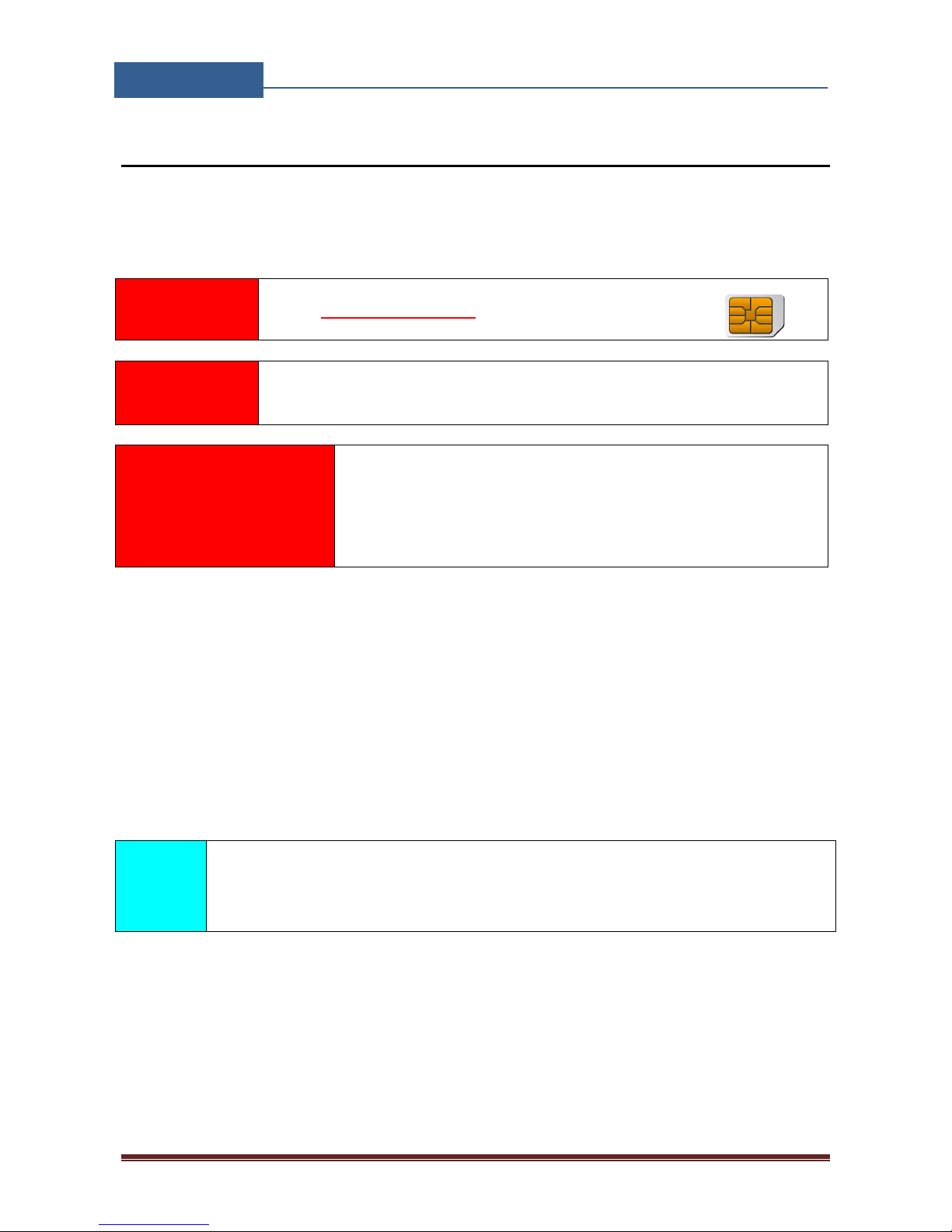
EIS unit accepts a standard GSM SIM (T-Mobile or AT&T)
card from any network.
VERY
IMPORTANT
USE A MICRO SIM CARD
WARNING
DO NOT Insert or remove the SIM card while the unit is powered ON!!
IMPORTANT
Before inserting SIM card to unit make sure the PIN code is
removed!!
⇒ Insert SIM card in EIS unit.
⇒ Connect power cable to EIS unit (YOU MUST POWER THE EIS UNIT WITH THE
POWER SUPPLY INCLUDED). Do not power with any other power supply.
⇒ Power up the unit.
⇒ Wait until LED1 (Blue) starts flashing. This is set in around 30 – 45 seconds.
⇒ EIS unit is now ready to operate.
NOTE
EIS will “beep” in 15s intervals until the unit reaches normal operation.
Page 9

EIS-LCD,!EIS-40!
USER!MANUAL!
Page%8%
5 LED INDICATION
Blue LED (LED1)
- Indicates the level of the GSM signal from 1 to 5 LED flashes (1 is weak signal, 5 is
excellent signal)
Red LED (LED2)
- GSM module Activity
Yellow LED (LED3)
- Short flashing indicates that the GSM module is ON, but it is not yet connected on the GSM
network. After connection, yellow led is flashing with short pulse (0,5s) ON and a long
pulse OFF (5s).
Page 10
EIS-LCD,!EIS-40!
USER!MANUAL!
Page%9%
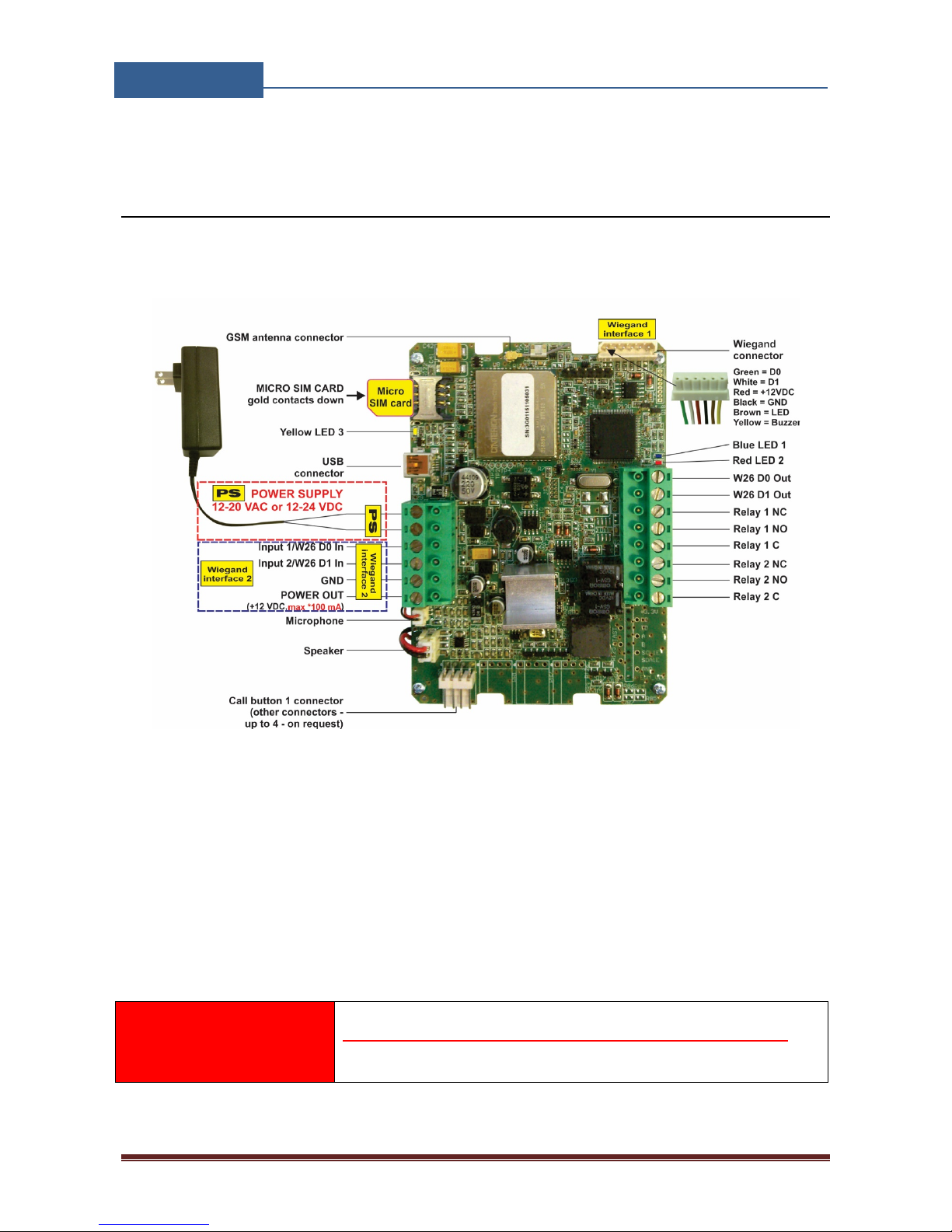
6 CONNECTION DIAGRAM
Before connection the EIS please take a look at connection diagram.
Figure 1: EIS Connection diagram.
IMPORTANT
DO NOT USE Power out (12V AUX) for electric lock driving! Use
separate power source for door electric lock!
Page 11

EIS-LCD,!EIS-40!
USER!MANUAL!
Page%10%
7 EIS MANAGEMENT
Unit supports different types of management (programming):
⇒ Unit can be programmed directly by USB connection, with the use of configuration software
running on PC (EIS Ware).
⇒ Unit can be programmed remotely by using WEB server access.
⇒ Unit can be programmed remotely by SMS commands (Optional).
Page 12
EIS-LCD,!EIS-40!
USER!MANUAL!
Page%11%
8 EIS FUNCTIONs with PROGRAMMING
INSTRUCTIONs
As mentioned in previous chapters EIS unit can be programmed in various ways, this document will
focus on most common programming way: WEB programming.
IMPORTANT
SIM card in the EIS unit MUST have DATA PLAN to be able to use WEB
programming!
8.1 WEB SERVER - LOG IN
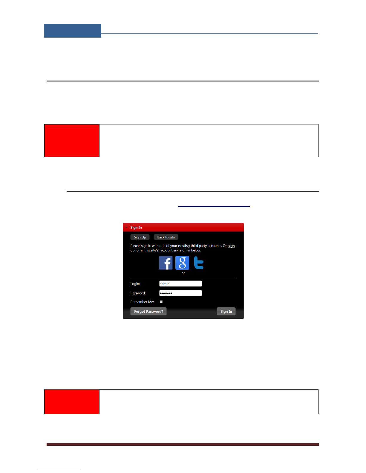
The web server can be found under the address: http://www.eisware.com/.
Figure 2: WEB Server-Sign In page.
User must first use the Sign IN section to create working profile on the server. The profile can be
created by using social login like Facebook, Google account or Twitter. If user lacks any of the
social profile it can proceed to Sign UP page use standard user name and password entry.
NOTE
Server support Firefox, Google Chrome, Safari.
Page 13
EIS-LCD,!EIS-40!
USER!MANUAL!
Page%12%
8.2 WEB SERVER – ADDING UNITS TO USER PROFILE
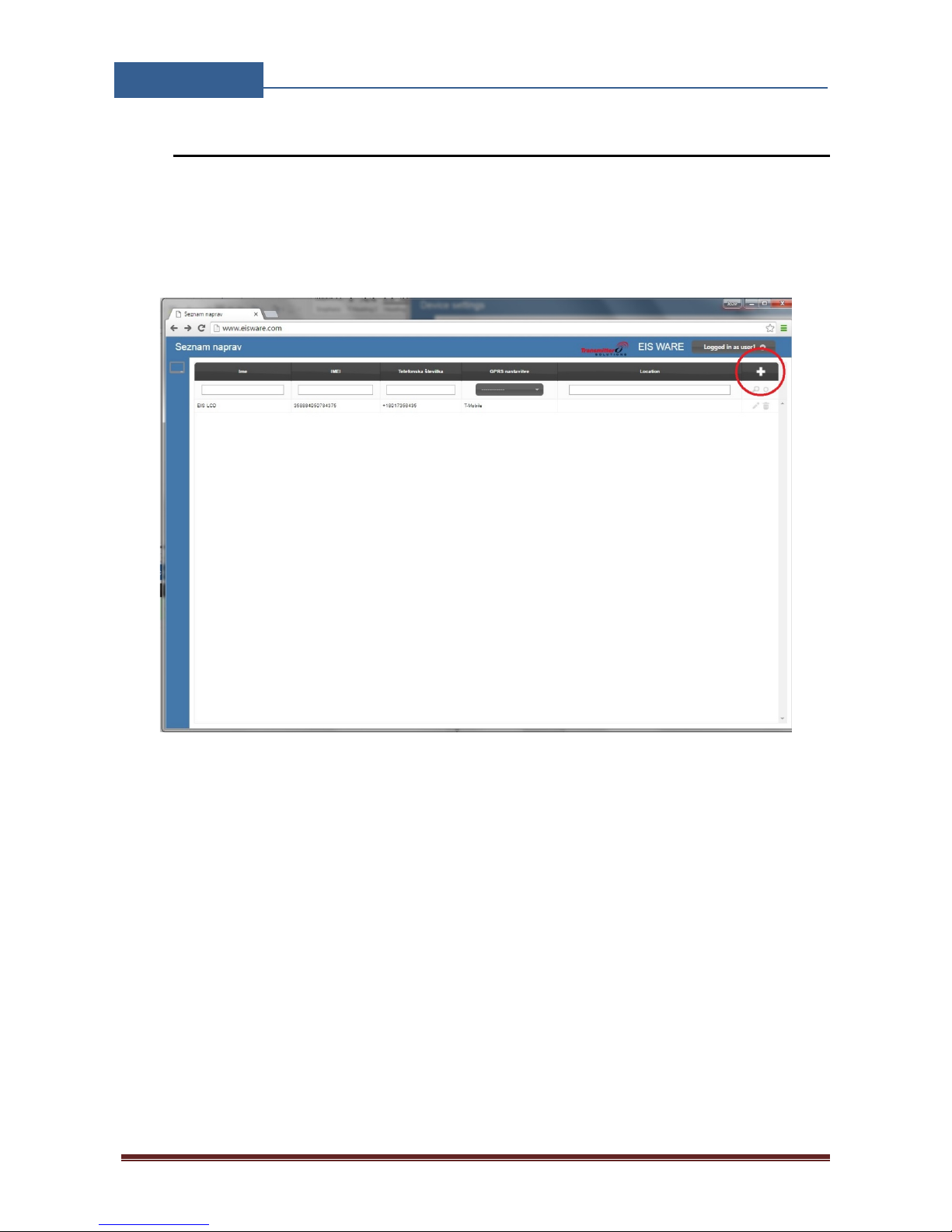
After login the user will be diverted to WEB server main window. This page is used to
add/remove/search for EIS units from the user’s profile.
Select “+” sign to select ADD EIS units to user’s profile.
Figure 3: WEB Server-Main page select ADD mode
Page 14
EIS-LCD,!EIS-40!
USER!MANUAL!
Page%13%
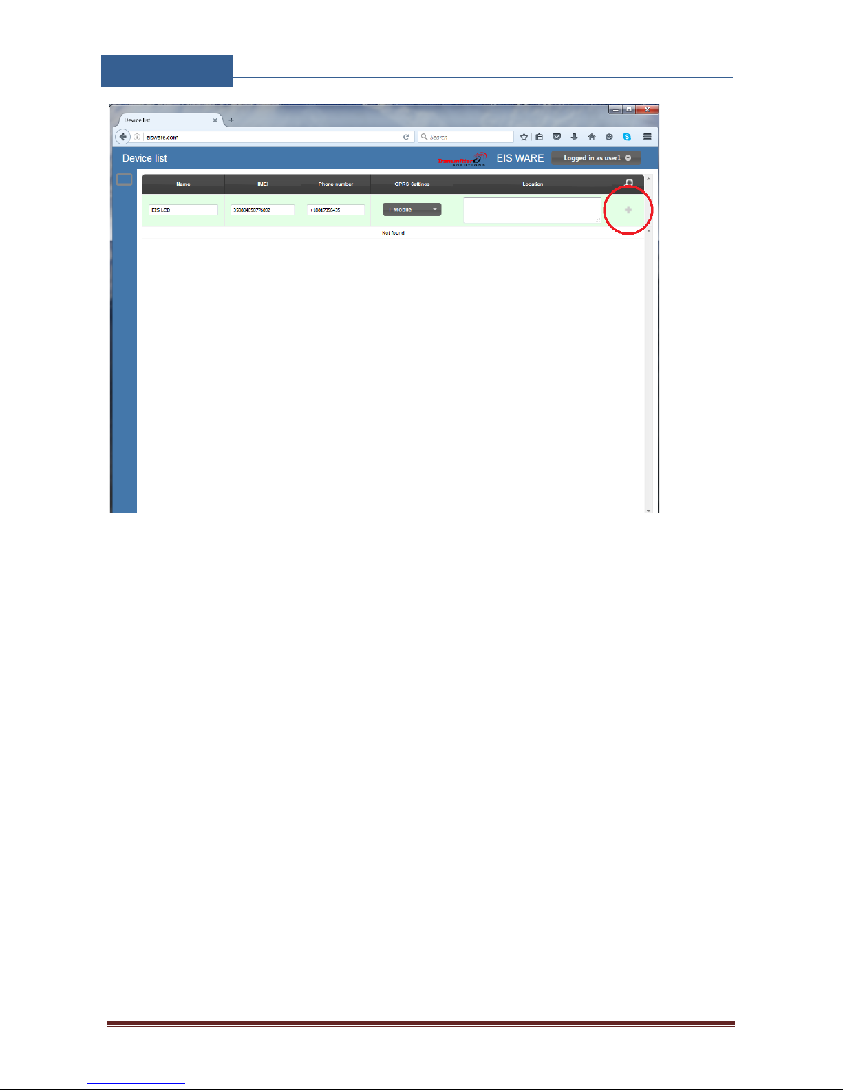
Figure 4: WEB Server-Main page adding EIS units
User than provides required data:
• Name: Name for the added unit - mandatory information.
• IMEI: Identification number of the unit, can be found in the enclosure of the unit -
mandatory information. The IMEI is located on the cellular chip and also should be on the
cardboard box of the EIS.
• Phone Number: The telephone number of the SIM card in the EIS unit - mandatory data.
• GPRS settings: Information needed to enable data connection between the server and the
unit. Selectable from the drop-down menu - mandatory data.
• Location: Notification field, used by the user to provide extra data for its own information -
optional data.
By clicking the “+” (insert sign) after filling mandatory data, the unit will be added to the user
profile.
First building of the unit database may take a few minutes.
Page 15
EIS-LCD,!EIS-40!
USER!MANUAL!
Page%14%
8.3 WEB SERVER-UNIT MANAGEMENT
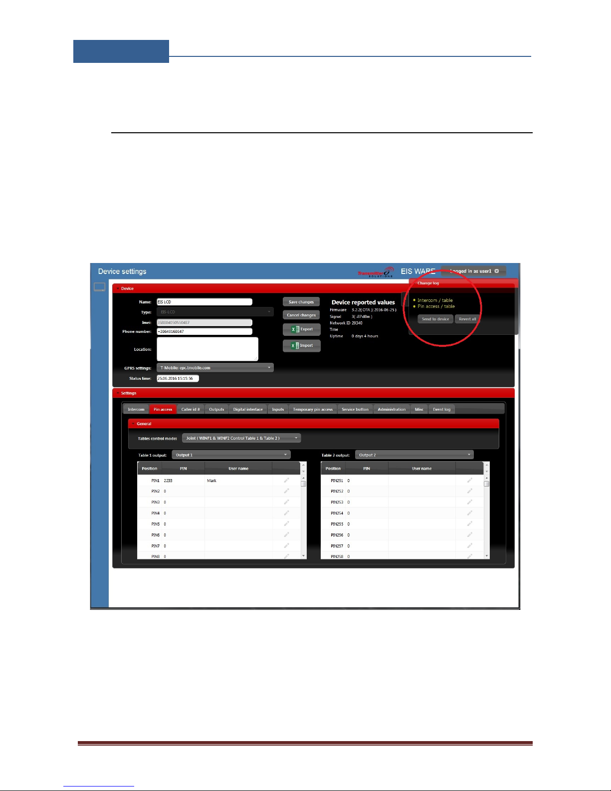
After the EIS unit is added to user database, the user can change the configuration of the specific
unit.
All changes made by the user are listed in the Change Log window. By clicking Send to device
button ALL changes are send to the unit. User can Revert all the changes made, before sending, by
clicking Revert all or select a particular entry and revert it.
Figure 5: WEB Server-Unit management window.
Page 16
EIS-LCD,!EIS-40!
USER!MANUAL!
Page%15%
8.4 INTERCOM CONFIGURATION
Primary function of the EIS unit is intercom support for multi-apartment use. Selecting (calling)
apartment number is achieved on two ways
- entering apartment number on the keypad and pressing # at the end.
- Selecting appropriate name with UP/DOWN arrows beside the LCD and press the CALL
button
Either of the actions will start a voice call procedure to Phone number 1 and Phone number 2.
After the call is answered the called user has the option to trigger the output by pressing “11” for
opening Output 1 or “21” for triggering Output 2.
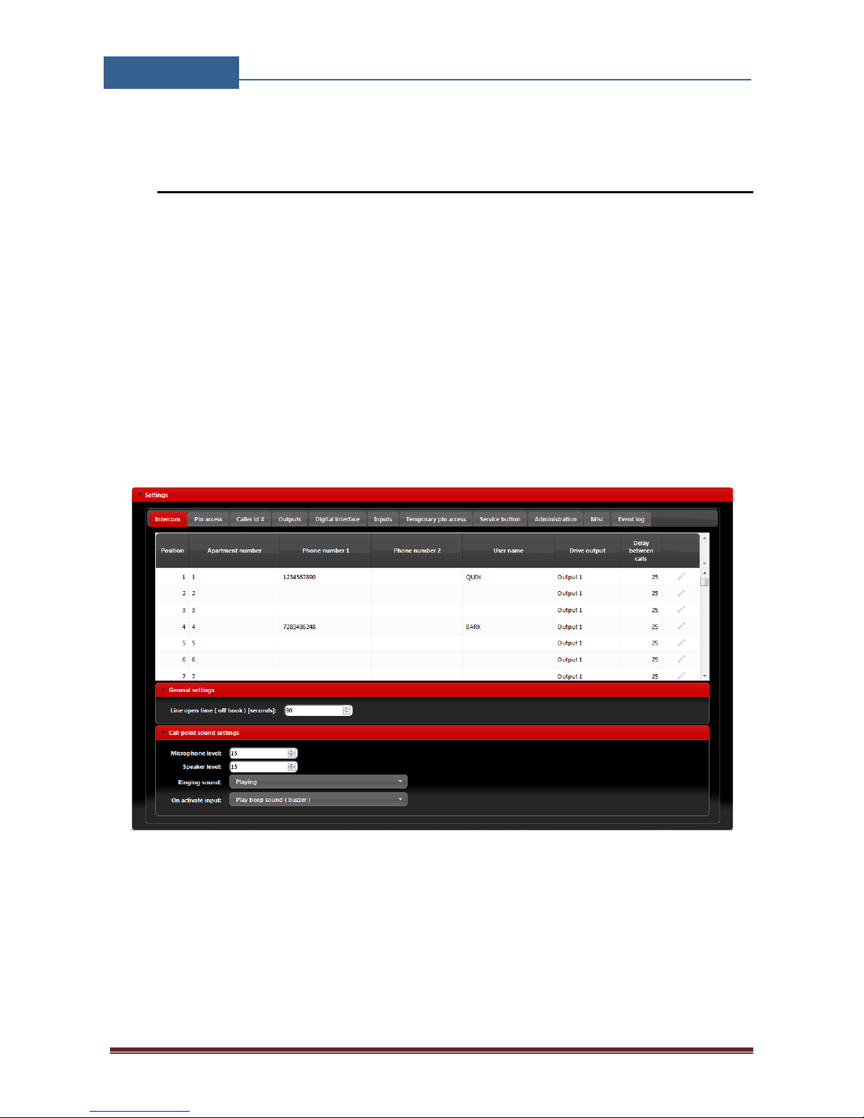
Management of the intercom function is found under Intercom tab.
Figure 6: WEB Server-Intercom settings.
Intercom management parameters:
• Apartment number: Dial code of the apartment.
• Phone number 1 & Phone number 2: 2 Numbers that the EIS unit will call when
appropriate apartment is selected on the keypad or selected on the LCD screen.
• User name: User name shown on the LCD screen.
Page 17

EIS-LCD,!EIS-40!
USER!MANUAL!
Page%16%
• Driver output: The output that will be triggered if the user with Phone number 1 or Phone
number 2 will call the unit (Caller Id function)
• Delay between calls: Ring time (in seconds) for Phone number 1 and Phone number 2.
After the ring time for Phone number 1 expires and the call is not answered the unit will
call Phone number 2.
• Line open time: Defines maximum in-connection time in second before the unit will
automatically disconnect the call.
Voice call setting
• Microphone level: Increasing the level will increase the sensitivity of the unit microphone
decreasing will decrease the sensitivity.
• Speaker level: Increasing the level will increase the volume of the unit speaker, decreasing
will decrease the level of the speaker.
• Ringing sound: By selecting Playing the unit will play the dial tone in the connection phase
of the call, by selecting Muted the unit will not play any sound in the connection phase of
the call.
• On activate input: By selecting Play beep sound (buzzer) the unit will provide audio feed
back (buzzer BEEP) when the apartment entry is selected, by selected Muted unit will
provide no audio feedback when the apartment entry is selected.
Page 18
EIS-LCD,!EIS-40!
USER!MANUAL!
Page%17%
8.5 KEYPAD PIN ENTRY – ACCESS
Secondary use of on-board keypad is access by entering PIN codes. Pin codes must be at least 4
digits.
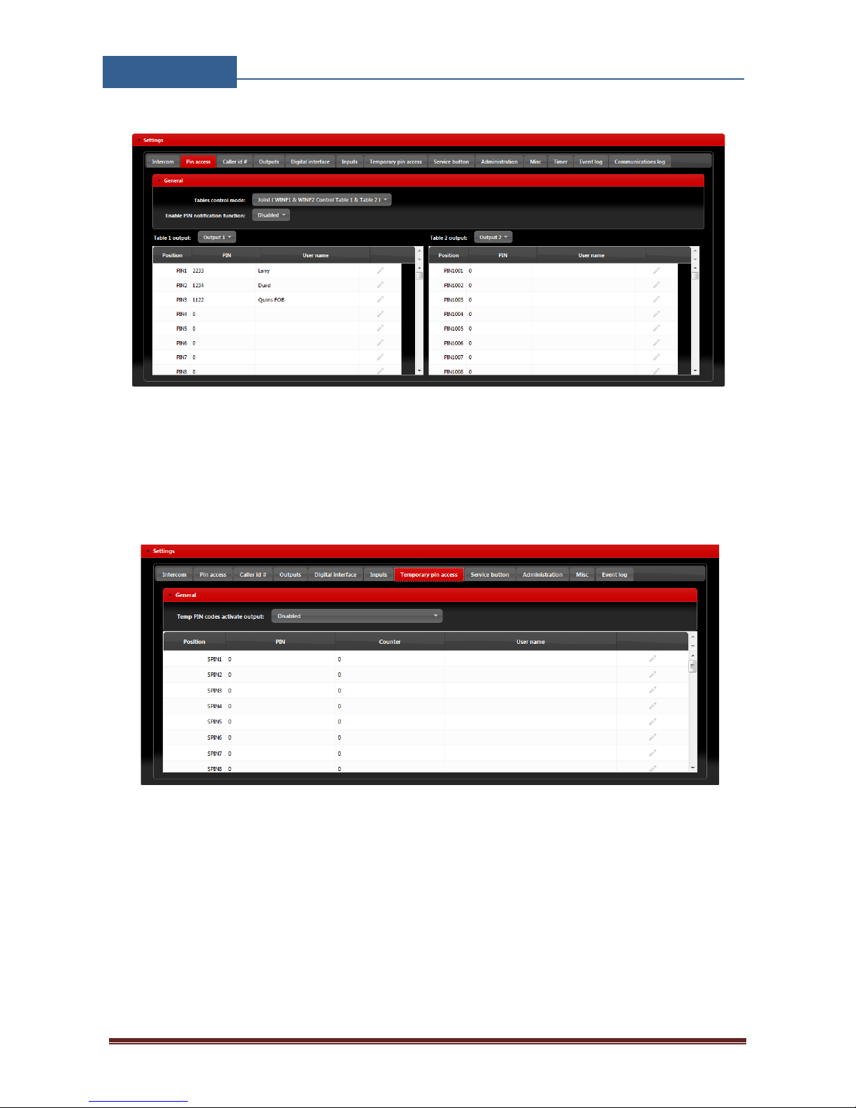
Pin codes can be defined in two sections. First section is permanent pin code and second is
temporary pin codes, which are limited by the consecutive time they are entered.
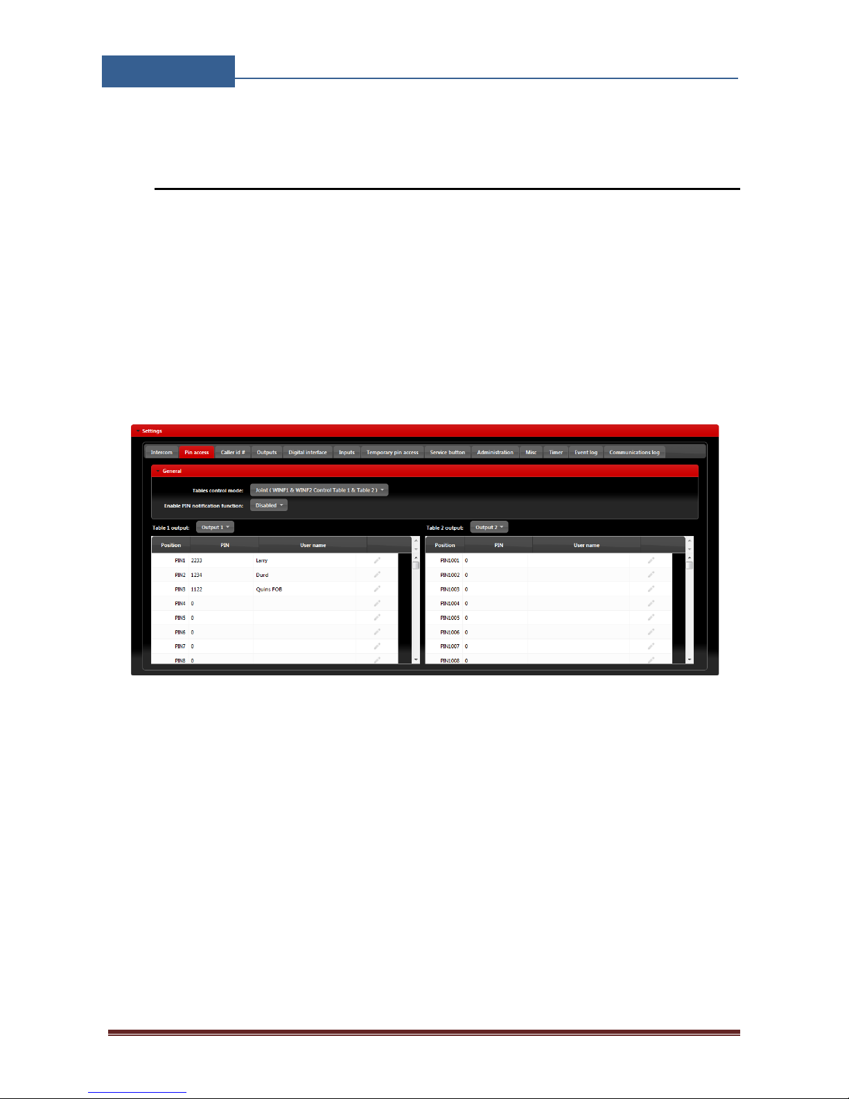
Permanent pin codes placed in Pin access tab.
Pin codes are placed in two tables. For each table user can define which output they will trigger.
Figure 7: WEB Server-Keypad PIN Access: Permanent PIN codes.
• PIN entry: For each PIN entry user need to select PIN code value and optional User name.
Page 19
EIS-LCD,!EIS-40!
USER!MANUAL!
Page%18%
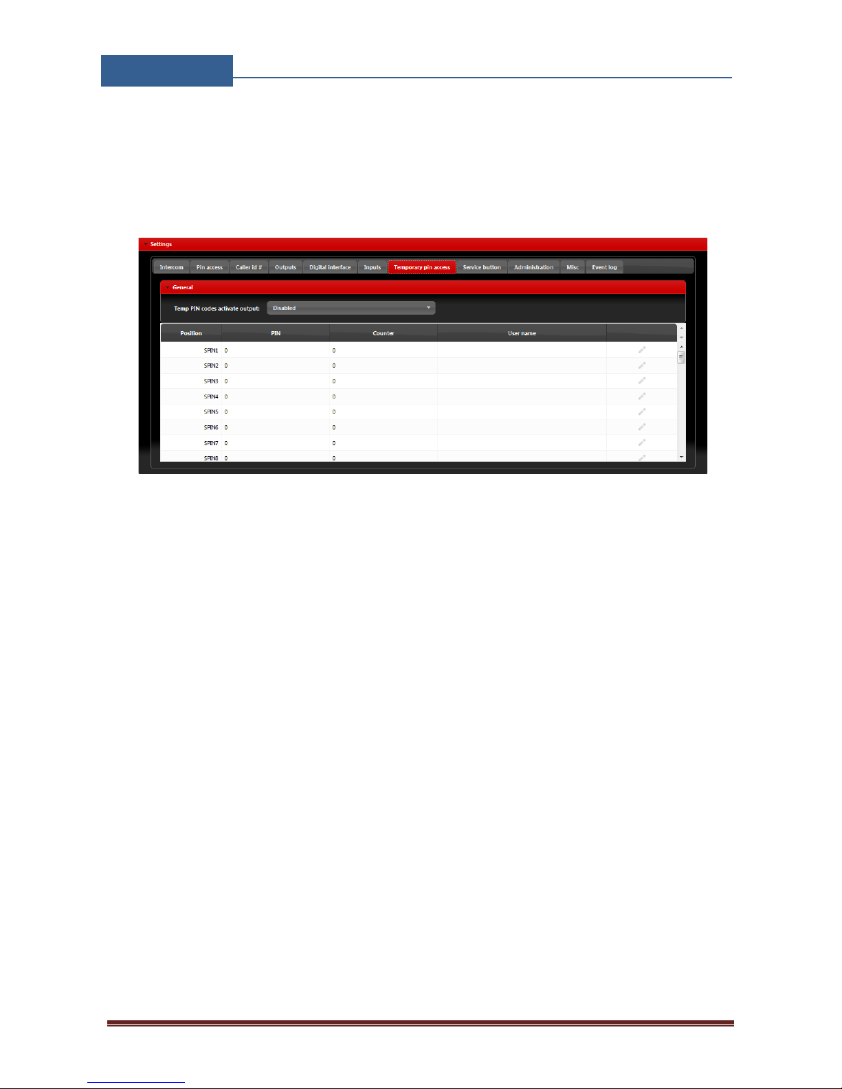
Temporary pin codes are placed in Temporary pin access tab.
Figure 8: WEB Server-Keypad PIN Access: Temporary PIN codes
• Temp PIN codes activate output: Selecting the output that will be triggered in case of
correct SPIN code.
• SPIN entry: For each SPIN entry user need to select PIN code value and Counter value
which defines how many time the PIN code will be valid and optional a User name. Counter
will be decreased each time SPIN code will be used
Page 20
EIS-LCD,!EIS-40!
USER!MANUAL!
Page%19%
8.6 WIEGAND ACCESS
EIS unit has onboard support for 2 Wiegand output based device. With the use of external replicator
more Wiegand devices can be connected to the unit.
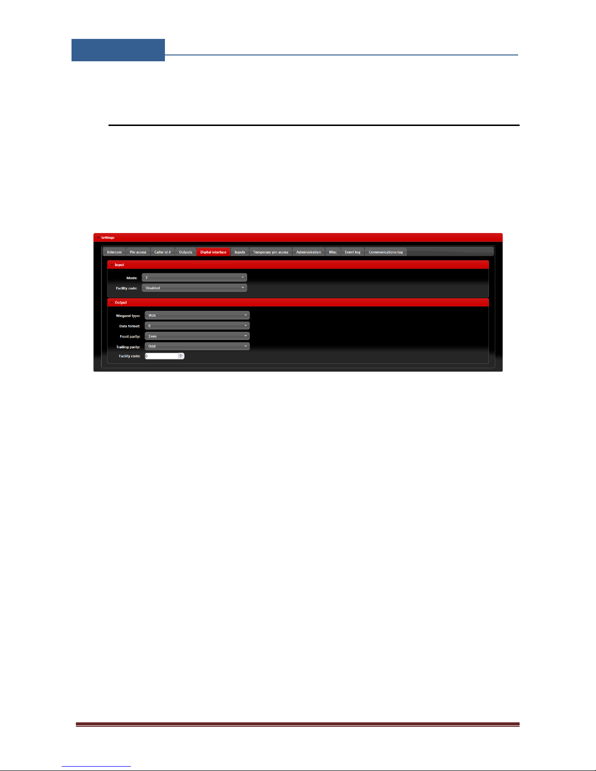
Configuration of first Wiegand interface is found in Digital interface tab. First Wiegand interface
can be found on board with a dedicated Wiegand connector and cables.
Figure 9: WEB Server-First Wiegand interface support.
• Mode: Select appropriate data formatting (Advise unit provider for more info if needed,
mode 2 is most common setting)
• Facility code: User can Enable or Disable facility code field.
Page 21
EIS-LCD,!EIS-40!
USER!MANUAL!
Page%20%
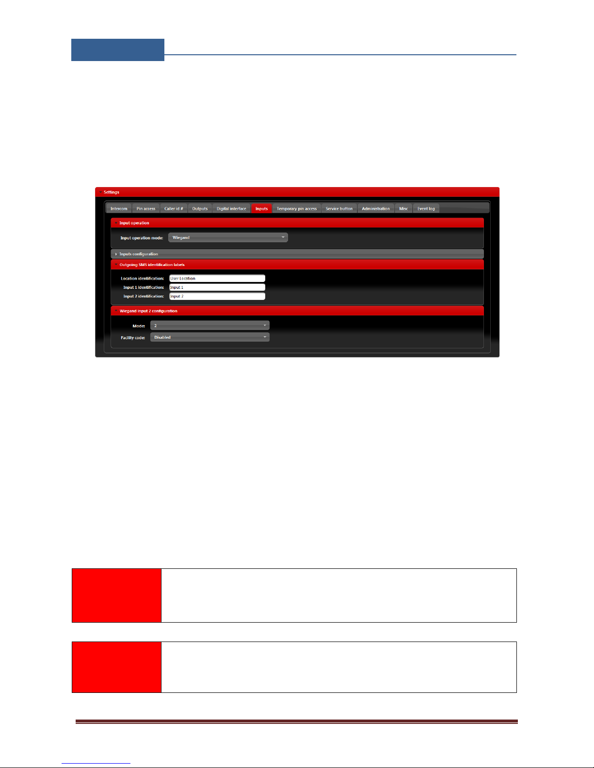
Second Wiegand interface is shared with alarm input lines, user must select Wiegand in Input
operation mode found in the Inputs tab.
Additional settings for Wiegand interface input are found in Wiegand input 2 configuration
sections.
Figure 10: WEB Server-Wiegand interface support.
• Mode: Select appropriate data formatting (Advise unit provider for more info if needed,
mode 2 is most common setting)
• Facility code: User can Enable or Disable facility code field.
Wiegand devices can be defined in two sections. First section is permanent use and second is
temporary use which is limited by the consecutive time they are used.
NOTE
See Chapter Error! Reference source not found.-Error! Reference source
not found. for detailed explanation of different data format options.
IMPORTANT
Unit MUST be restarted when switching between Normal and Wiegand mode
in the Input operation mode.
Permanent use: devices are added in Pin access tables.
Page 22
EIS-LCD,!EIS-40!
USER!MANUAL!
Page%21%
Figure 11: WEB Server-Adding Wiegand devices with permanent use.
• PIN entry: For each PIN entry user need to select PIN code value and optional User name.
Temporary pin codes are placed in Temporary pin access tab.
Figure 12: WEB Server-Adding Wiegand devices with temporary use.
• Temp PIN codes activate output: Selecting the output that will be triggered in case of
correct SPIN code.
• SPIN entry: For each SPIN entry user need to select PIN code value and Counter value
which defines how many time the PIN code will be valid and optional a User name. Counter
will be decreased each time SPIN code will be used.
Page 23
EIS-LCD,!EIS-40!
USER!MANUAL!
Page%22%
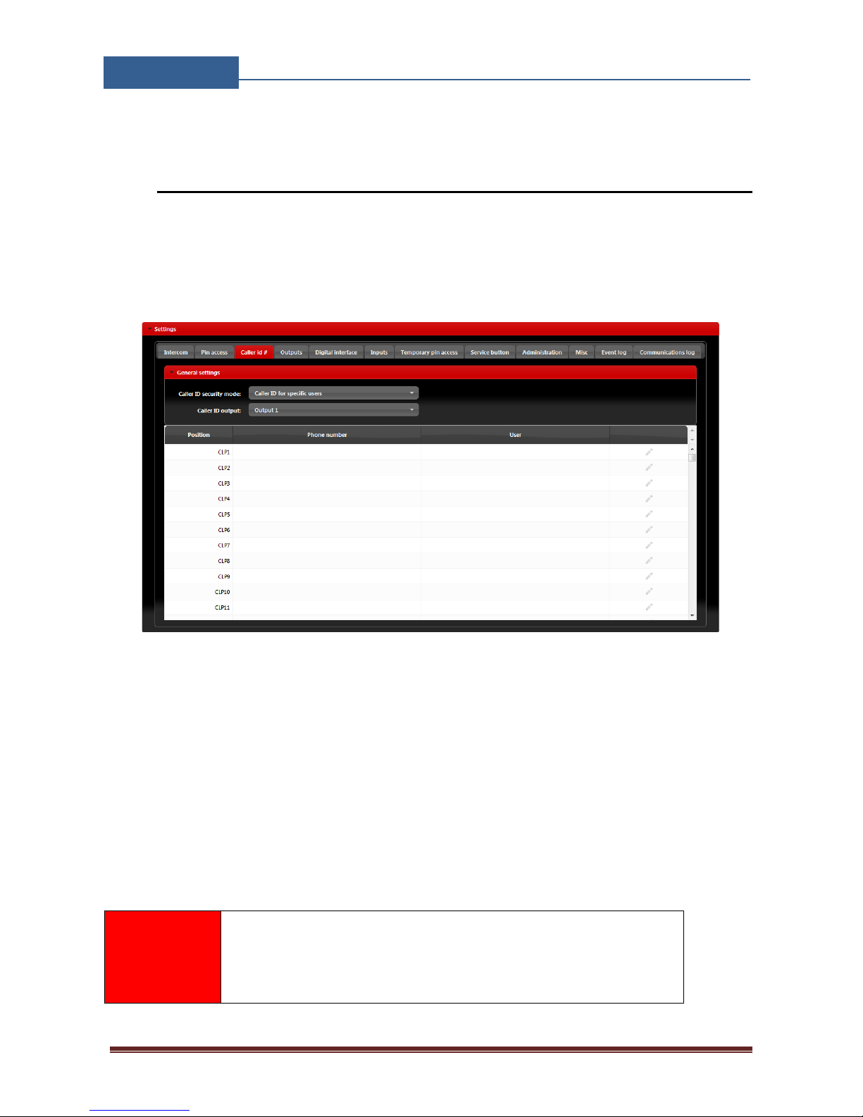
8.7 CALLER ID ACCESS
Caller ID access is a very simple way to control relay output defined in Caller ID output setting.
User will by calling in the EIS unit trigger defined output.
Settings for this function are found in the Caller id # tab.
Figure 13: WEB Server-Caller ID Access.
General settings:
• Caller ID security mode: User can select between 3 options:
Caller ID Disabled deactivates caller ID function – all numbers are restricted
Caller ID for specific users will limit the caller ID function only to the numbers on the list.
Caller ID always ON will allow all user that know the number of the unit to open defined
output. In last option the user doesn’t need to be on the list to trigger the output
• Caller ID output: Selecting the output that will be triggered in Caller ID function.
NOTE
Selection Caller ID always ON will allow anybody with the
knowledge of the SIM card number un the EIS unit to trigger the
output by calling the unit. Use this setting with caution.
Page 24
EIS-LCD,!EIS-40!
USER!MANUAL!
Page%23%
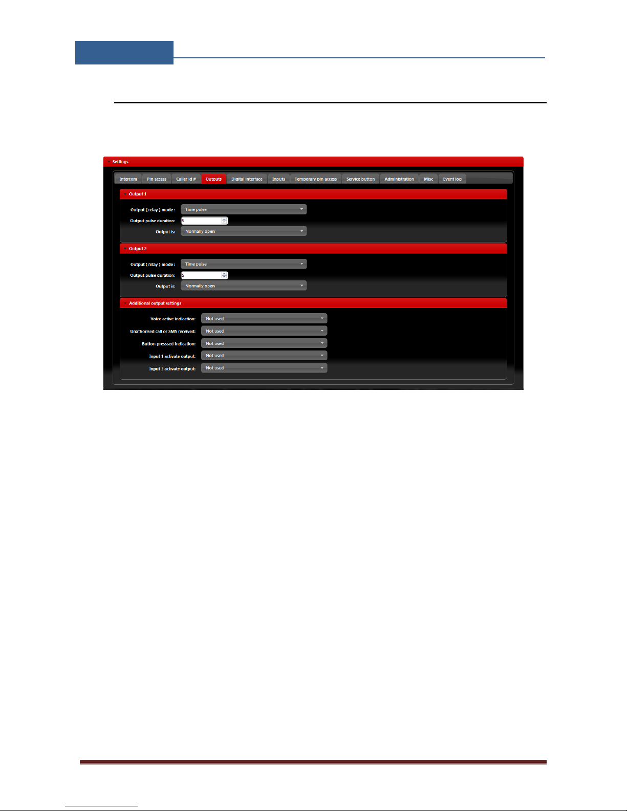
8.8 OUTPUTS SETTINGS
The behavior on the outputs is defined in the Output tab.
Figure 14: WEB Server-Output setting
Output 1- Settings for output 1:
• Output (relay) mode: User can select between 3 options
Disable-Output is disabled
Latching-Output is in latching mode. First Caller ID or PIN entry will activate the output,
second Caller ID or PIN entry will deactive the output.
Time Pulse-Output is time pulse mode. After output is triggered it will be activated for the
time defined in Output pulse duration, after that time output will be restored.
• Output pulse duration: ON time for output in case of output mode Timer pulse.
• Output is: Output can work in normal or inverted (normally close) mode.
Normally open-In idle mode output pins are in open position.
Normally closed-In idle mode output connection are closed.
Page 25
EIS-LCD,!EIS-40!
USER!MANUAL!
Page%24%
Output 2 - Settings for output 2:
• Output (relay) mode: User can select between 3 options
Disable-Output is disabled
Latching-Output is in latching mode. First Caller ID or PIN entry will activate the output,
second Caller ID or PIN entry will deactive the output.
Time Pulse-Output is time pulse mode. After output is triggered it will be activated for the
time defined in Output pulse duration, after that time output will be restored.
• Output pulse duration: ON time for output in case of output mode Timer pulse.
• Output is: Output can work in normal or inverted (normally close) mode.
Normally open-In idle mode output pins are in open position.
Normally closed-In idle mode output connection are closed.
Additional output settings - Setting are used to link onboard actions with the outputs if needed:
• Voice active indication: When unit reaches voice connection (intercom call) output
defined under this section gets activated.
• Unauthorized call or SMS received: If unauthorized call or SMS is received on the unit
this event will activate output defined under this section.
• Button pressed indication: When intercom call button is pressed output defined under this
section gets activated.
• Input 1 activate output: If input 1 is in alarm mode (Input operation mode: Normal mode
selected) alarm input event on the input will activate output defined under this section.
• Input 2 activate output: If input 2 is in alarm mode (Input operation mode: Normal mode
selected) alarm input event on the input will activate output defined under this section.
NOTE
Do to limitation of the outputs use additional outputs settings with care.
Page 26
EIS-LCD,!EIS-40!
USER!MANUAL!
Page%25%
8.9 EIS WIEGAND OUTPUT INTEGRATION
EIS unit can be integrated into a bigger access system using a Wiegand interface. In this case
numbers calling the unit will be transferred, over Wiegand interface, to access system.
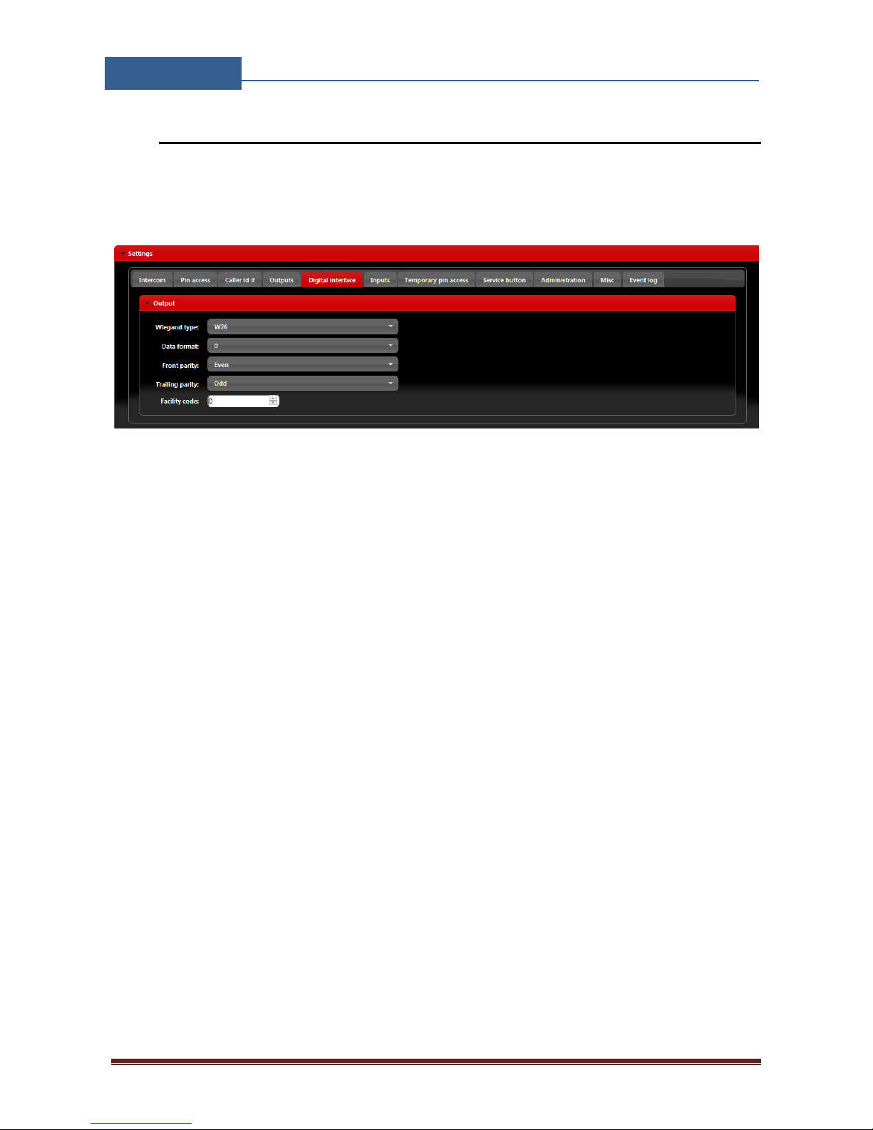
Figure 15: WEB Server-Wiegand Output settings.
Configuration of the Wiegand output interface
• Wiegand Type: Type of the Wiegand used (W26 is most common setting)
• Data format: Format of data set on the selected Wiegand type.
• Front parity, trailing parity: Selection of the proper parity in selected Wiegand type.
• Facility code: Is required, user can define facility code to Wiegand data.
Page 27
EIS-LCD,!EIS-40!
USER!MANUAL!
Page%26%
8.10 TIMER-TIMED CONTROLED OUTPUT
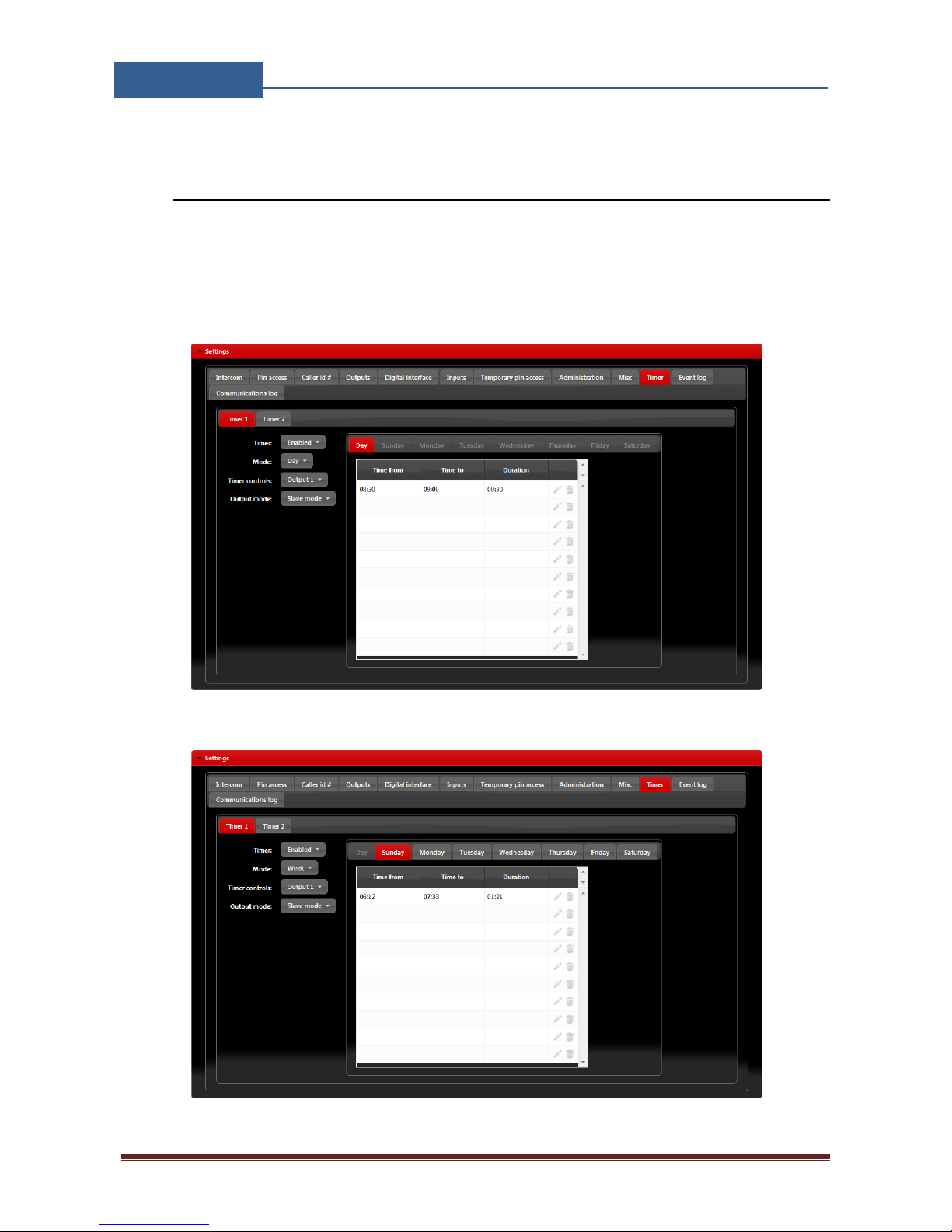
EIS unit features 2 timers that can be used to control the outputs on the unit. Timers can run in day
or week mode depending on the selected setting. For each timer user can select which output it will
control.
Figure 16: WEB Server-Timer setting →Day mode.
Figure 17: WEB Server-Timer setting →Week mode.
Page 28

EIS-LCD,!EIS-40!
USER!MANUAL!
Page%27%
User can select two different modes how the outputs are managed:
1. Slave mode: the behavior of the outputs (Time pulse or Latching mode) is defined in the
Output tab.
2. Master mode: when the output is driven by the timer (output is activated by the timer) the
outputs are in latching mode regardless of the setting in Output tab. When the output is not
activated by the timer, the outputs are working by the defined settings in Output tab.
The described settings are the same for both timers.
Timer settings:
• Timer: Parameter is used to enable and disable the timer function.
• Mode: User can select between day or week mode. In day mode the timer will control on
the day table, which is the same for all week. In week mode the user can define different
setting for each day in the week.
• Timer controls: Output controlled by the timer function.
• Output mode: Output mode management definition.
Page 29
EIS-LCD,!EIS-40!
USER!MANUAL!
Page%28%
8.11 SERVICE BUTTON
Service button is a dedicated button that is used to directly call numbers or directly trigger defined
output on the EIS unit.
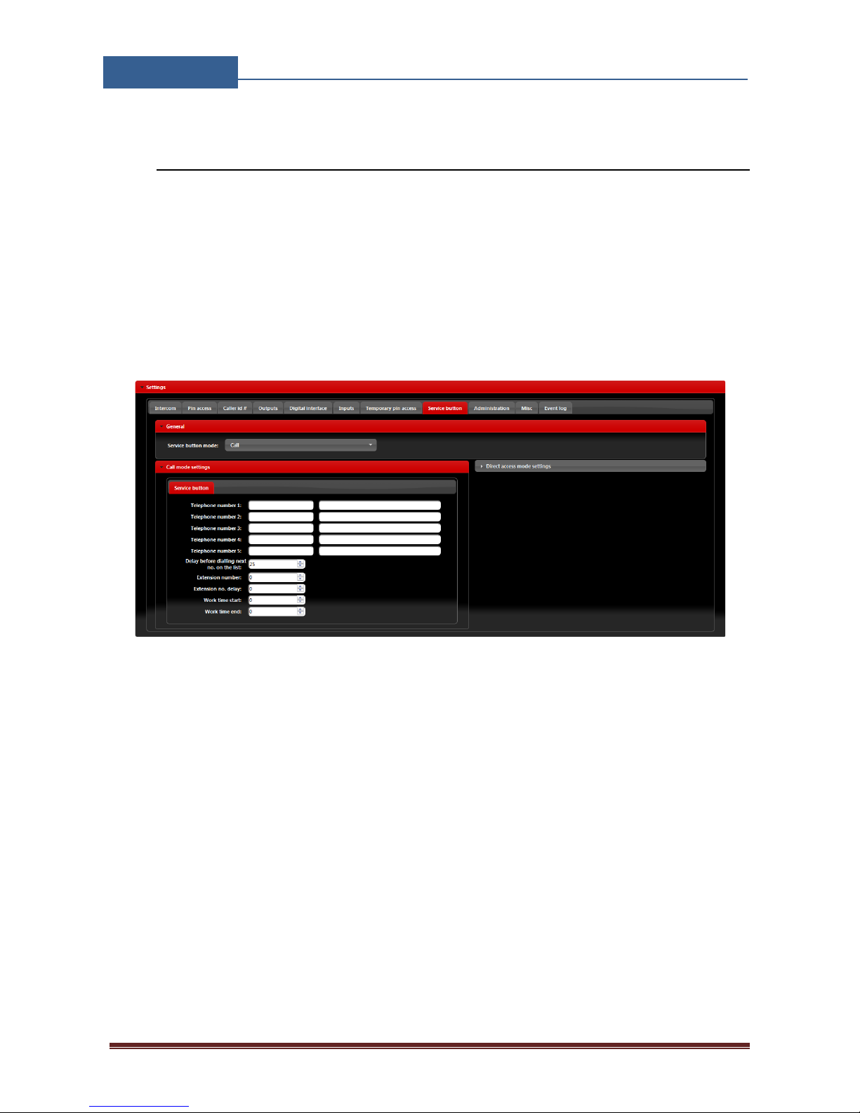
In case of Call mode is selected in the Service button mode, unit will call number defined. If
needed it is possible to define work hour schedule. In working time limits, unit will call first 4
number defined, out of working time limits unit will call 5th number defined.
Figure 18: WEB Server-Service button settings (Call mode).
Call mode settings
• Telephone number 1…Telephone number 5: Number that the unit will call if button
pressed.
• Delay before dialing next no. on the list: Time delay in second before next user on the list
gets dialed if the call to the previous user is not answered.
• Extension number: Parameter is used to set the DTMF number in auto self-select function
• Extension no. delay: Parameter is used to set the delay (in sec.) for sending DTMF number
in auto self-select function.
• Work time start, Work time end: Parameters are used to define work time schedule.
Inside this limits number under position 1 to 4 will be dialed, outside this limits number
under position 5 will be dialed.
Page 30
EIS-LCD,!EIS-40!
USER!MANUAL!
Page%29%
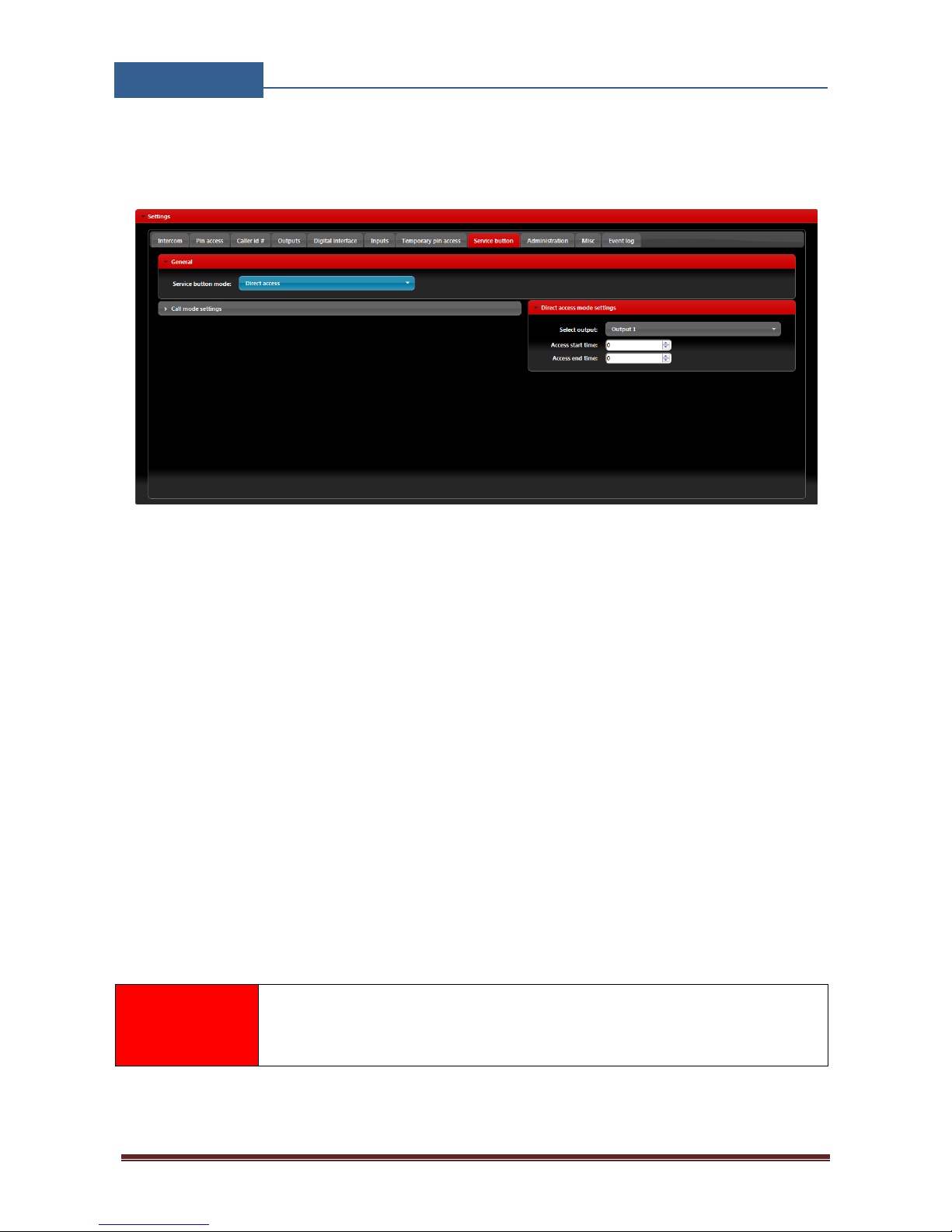
In case of Direct access mode is selected in the Service button mode, service button press will
activate output defined.
Figure 19: WEB Server-Service button settings (Direct access).
Direct access settings
• Select output: The output that will be triggered if service button is pressed
• Access start time, Access end time: Parameters are used to define work time schedule. If
limits defined than only inside this limits the output defined gets triggered. If 24h access is
needed don’t use this limits.
NOTE
Service button is a special button that may/or may not be a part of the EIS
unit. Please advise your installer if this function is needed.
Page 31
EIS-LCD,!EIS-40!
USER!MANUAL!
Page%30%
8.12 ADMINISTRATION
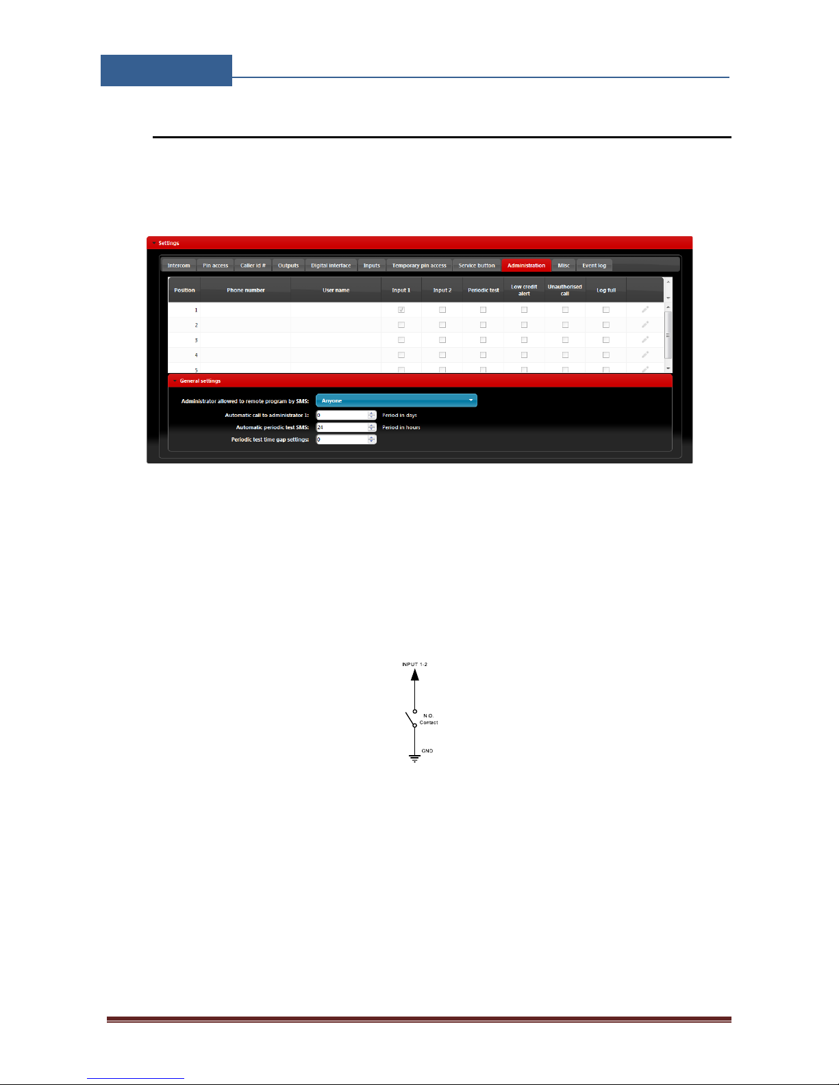
Administration tab allows user to enable advanced settings like notification of unauthorized access,
periodic test messages, lock down of the unit…
Figure 20: WEB Server-Notification numbers.
• Phone number, User name: Phone number and user name of the user that will be receiving
notification messages.
• Input 1, Input 2: If input lines 1 & 2 are defined in alarm mode (Input operation mode:
Normal mode) and if alarm condition is meet, users with check boxes will receive alarm
notification SMS.
Figure 21: WEB Server-Input alarm configuration.
• Periodic test: User can receive periodic (keep-alive) SMS, tick the check box for the
appropriate user. Timer period is defined under parameter Automatic periodic test SMS, it
is definable in hours
• Low credit alert: In case of prepaid SIM card the unit can notify the user if the credit on the
SIM card is low. To enable notification SMS tick the check box in corresponding position.
Note that additional input in the Misc tab is needed to fully enable credit-checking function.
Page 32
EIS-LCD,!EIS-40!
USER!MANUAL!
Page%31%
• Unauthorized call: In case of unauthorized call the unit can notify user. To enable
notification SMS tick the check box in corresponding position.
• Administration allowed to remote program by SMS: By selection this option the user
can “Lock down” the EIS unit, preventing any unauthorized user to change any
configuration on the unit.
• Automatic call to administrator 1: To prevent SIM card provider to lock out the SIM card
from the network, user can define a periodic call out to telephone number under position 1.
Parameter is defined in days (It is not mandatory to set this parameter).
8.13 EVENT LOGING
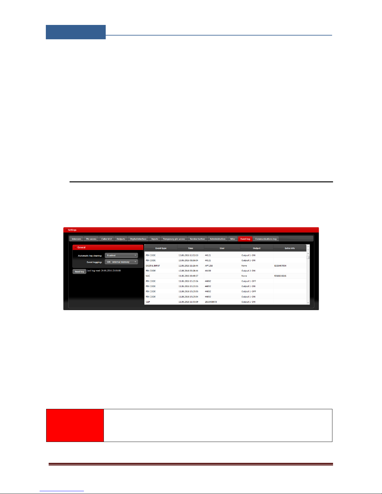
EIS unit itself supports a 20000 log event entry. These log events can be pull up to the server by
clicking Read Log button in the “Event Log” tab. Events are listed in the table.
Figure 22: WEB Server-Log events.
Each event is equipped with the event type, time, output if triggered and the user name of the user
responsible for the event.
If user names are available (Called ID #, PIN codes, Intercom user …) user name will be shown in
the user column.
NOTE
After events are read and stored to the server, the local copy on the unit gets
deleted.
Page 33
EIS-LCD,!EIS-40!
USER!MANUAL!
Page%32%
8.14 MISCELLANEOUS
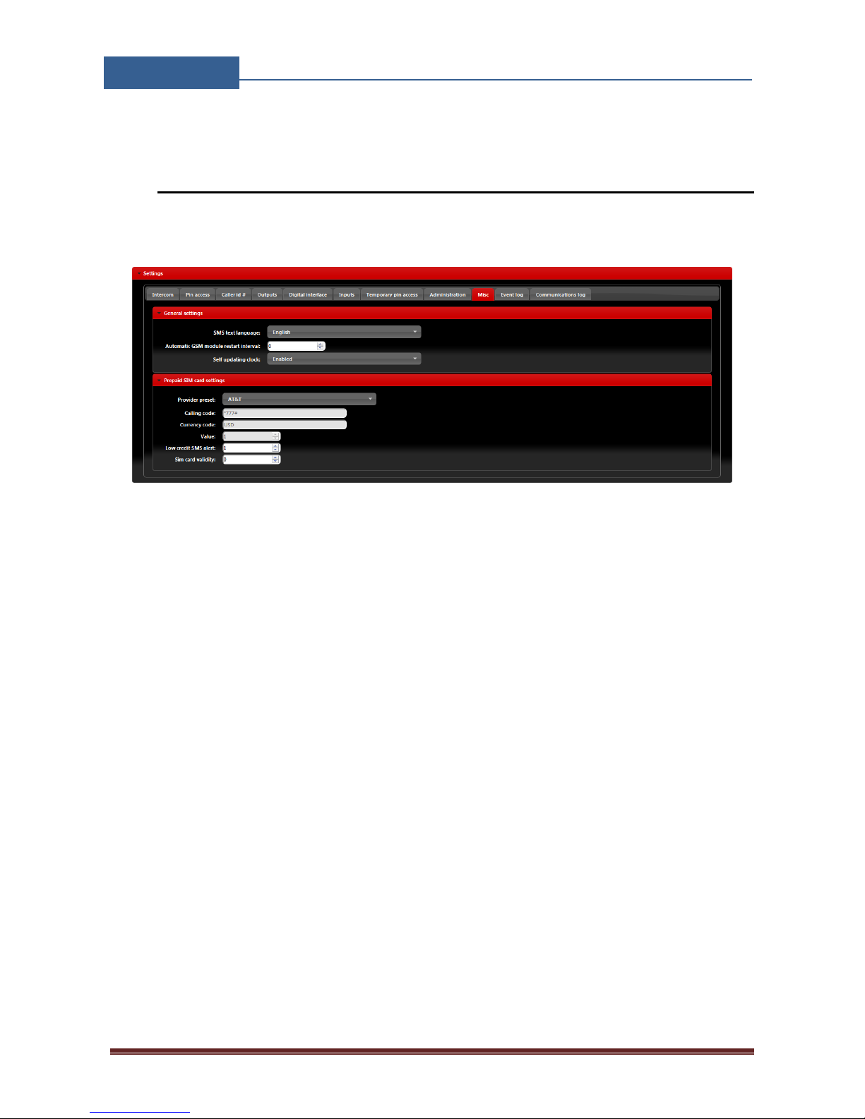
This tab is split into 2 sections.
Figure 23: WEB Server-Misc.
General settings can be found:
• SMS text Language: define the language of the SMS information send out. User can select
appropriate language in drop-down menu.
• Automatic GSM module restart interval: User can select GSM module restart interval
(hours) if needed (Not advisable to use this parameter if not advised otherwise).
• Self-updating clock: Parameter is used to allow unit to synchronize to real time. To have
the correct time along in log event it is advisable to enable this function.
Prepaid SIM card setting is used the enable credit checking/parsing in case if prepaid SIM card is
used. User can select the proper setting by selecting used SIM card provider in the drop down menu
in Provider preset.
Page 34
EIS-LCD,!EIS-40!
USER!MANUAL!
Page%33%
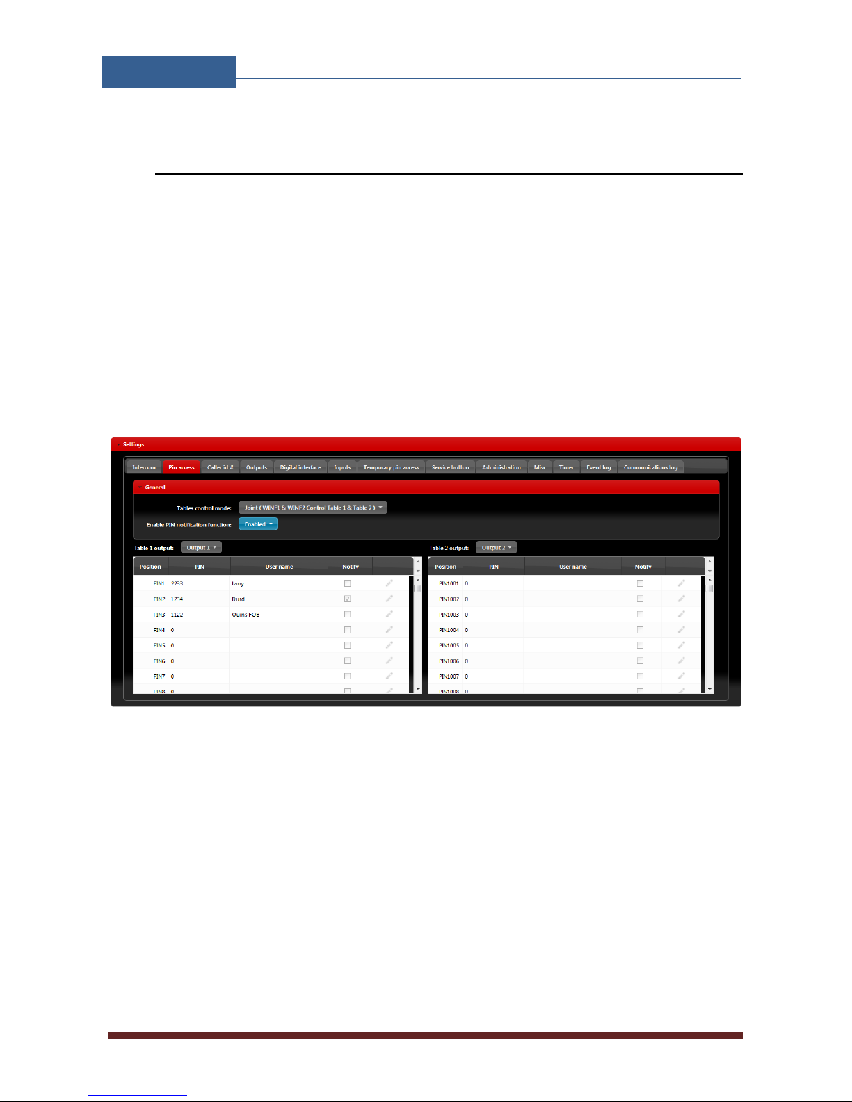
8.15 PIN ACCESS NOTIFICATION FUNCTION
This function is used to notify administrator when a selected pin code is being used. Notification is
done by SMS send to the selected administrator numbers.
Global enabling of the notification function is done in 2. steps.
STEP 1: User has to select Enable option in the Enable Pin Notification function.
STEP 2: Send the configuration to the device!!
This procedure is ONLY done 1 time when enabling this function.
Figure 24: WEB Server-Global enabling of the notification function.
After the notification function is enabled, user can select which pin code will send the notification
SMS. This is done by placing a tick in the check box of the pin code notify field.
Page 35
EIS-LCD,!EIS-40!
USER!MANUAL!
Page%34%
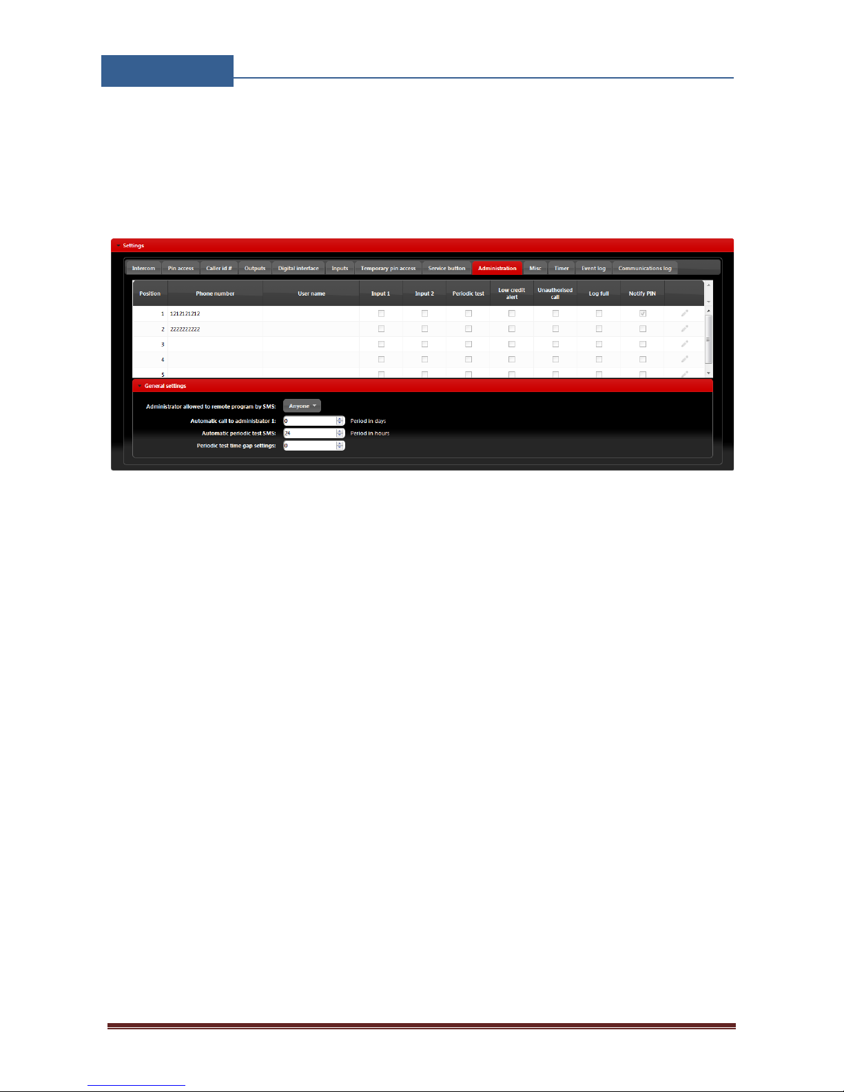
The last step is selecting a number that will be receiving the notification SMS. Selecting is done in
the Administration tab. In the Notify PIN column put a tick in the check box for the appropriate
phone number, multiple choices are possible.
Figure 25: WEB Server-Selecting administrator numbers for notification.
Page 36

EIS-LCD,!EIS-40!
USER!MANUAL!
Page%35%
9 SMS Commands
Basic SMS commands for unit listed.
9.1 INTERCOM SETTINGS
Settings of the call group
x is number of the call groups (1 to 200/500/1000).
⇒ ;KPAx=number 1; – First number on the list
⇒ ;KPBx=number 2; – Second number on the list
⇒ ;KPNx=apt. num; – Apartment dial code
⇒ ;KPTx=delay; – Delay before calling second number in seconds
⇒ ;KPOx=output; – Called id output control ( output is 1 or 2 )
Checking the output settings with command:
;PKP=x,y; x-first group for print out, y-last group for print out
Audio level
Setting microphone level
⇒ ;MIC=value; – Microphone sound level (0 to 40)
Setting speaker level
⇒ ;SPK=value; – Speaker sound level (0 to 20)
Checking the output settings with command:
;PPA;
9.2 OUTPUT CONFIGURATION
EIS unit has 2 dedicated relay supported outputs. Outputs can be configured to different behavior:
x is number of the output (1 or 2).
⇒ ;OSx=0; – Output Disabled
⇒ ;OSxR=1; – Latching
⇒ ;OSxR=y; – Pulse mode, y=time is seconds
Checking the output settings with command:
;POS;
Page 37

EIS-LCD,!EIS-40!
USER!MANUAL!
Page%36%
9.3 PIN CODES SETTINGS
Setting pin codes:
Selecting notification function for pin codes
⇒ ;NOTF=0; – Disable notification function
⇒ ;NOTF=1; – Enable notification function
If notification is enable 2 further steps need to be taken
Definition of administrator numbers
x is number of telephone numbers that can receive notification SMS (1 to 5).
⇒ ;TNx=number; – Telephone number
Definition of administrator numbers that WILL receive SMS notification
⇒ ;LNN=xyz; – selection of administration numbers that will receive SMS
Example: ;LNN=134; --administrators under TN1, TN3 and TN4 will get notification
PIN code entry if NOTIFICATION FUNCTION IF OFF ;NOTF=0;
x is number of the call groups (1 to 2000).
⇒ ;PINx=pin code; – Pin code, at least 4 digits
Checking the output settings with command:
;PPIN=x,y; x-first pin code for print out, y-last pin code for print out
PIN code entry if NOTIFICATION FUNCTION IF ON ;NOTF=1;
x is number of the call groups (1 to 2000).
⇒ ;PINx=pin code,0; – Pin code, at least 4 digits, notification for this pin code is OFF
⇒ ;PINx=pin code,1; – Pin code, at least 4 digits, notification for this pin code is ON
Checking the output settings with command:
;PPIN=x,y; x-first pin code for print out, y-last pin code for print out
9.4 SMS OUTPUT CONTROL
Controlling of the output by sending SMS:
x is number of the output (1 or 2).
⇒ ;ORCx=ON; – Switch ON the output
⇒ ;ORCx=OFF; – Switch OFF the output
Checking the output settings with command:
;PORC:
Page 38
EIS-LCD,!EIS-40!
USER!MANUAL!
Page%37%
10 ADVANCED FUNCTIONS
A short manual addressing advanced function to be found on different EIS units.
10.1 WIEGAND INPUT DATA FORMATS
Units addressed: EIS-1, EIS-2, EIS-4, EIS-R, EIS-LCD, EIS-40
EIS units support standard Wiegand interface, it will work with Wiegand 26bit and Wiegand 30bit
protocol. On each Wiegand protocol EIS unit support 4 different data formats, they all can be
selected through all possible management systems.
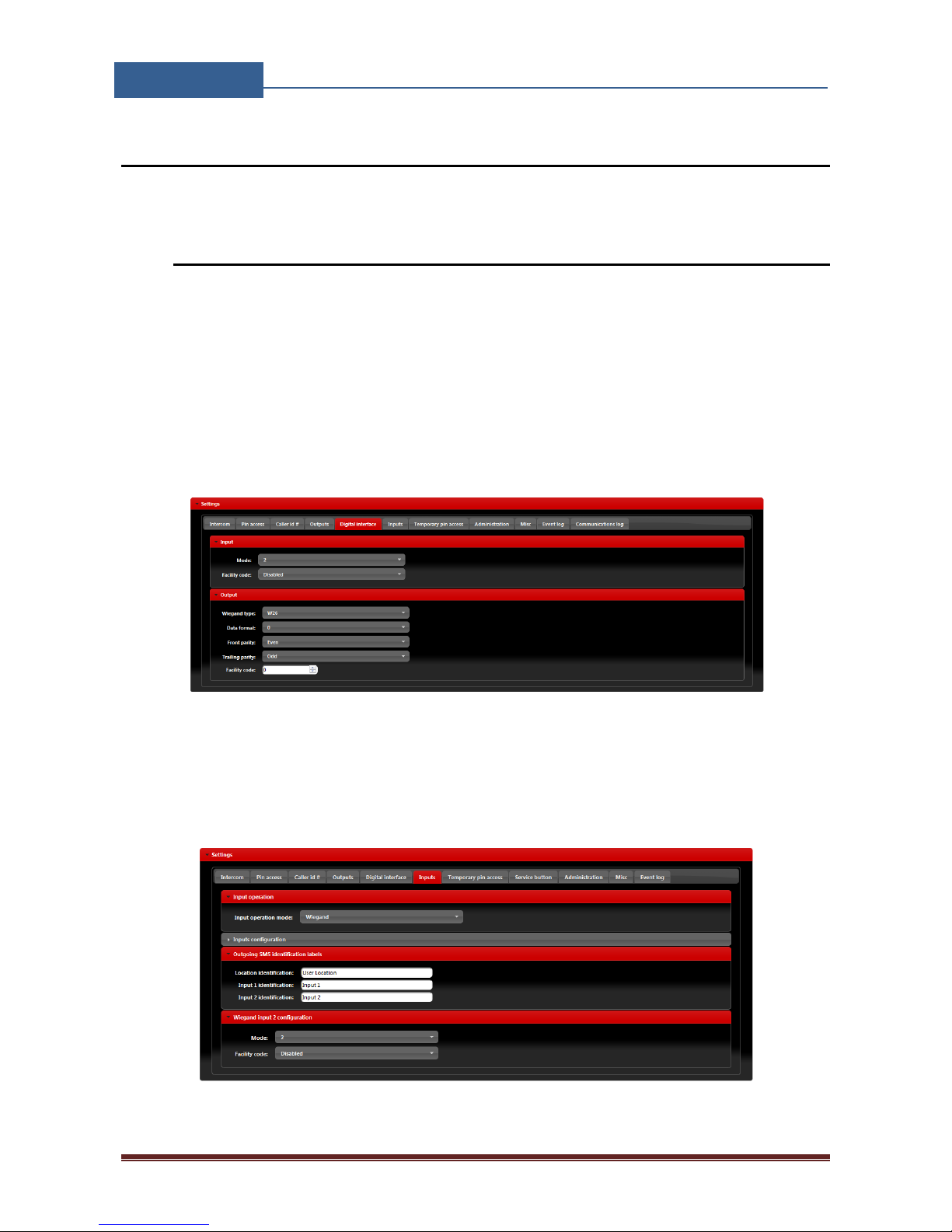
Selecting the appropriate data format for FIRST Wiegand interface is done by connecting the WEB
server, selecting the Digital interface and in Input section selecting proper Mode option.
Figure 26: WEB Server-First Wiegand interface support.
Selecting the appropriate data format for SECOND Wiegand interface is done by connecting to the
WEB server, selecting the Input tab and in Wiegand input 2 configuration section selecting
proper Mode option.
Figure 27: WEB Server-Second Wiegand interface support.
Page 39
EIS-LCD,!EIS-40!
USER!MANUAL!
Page%38%
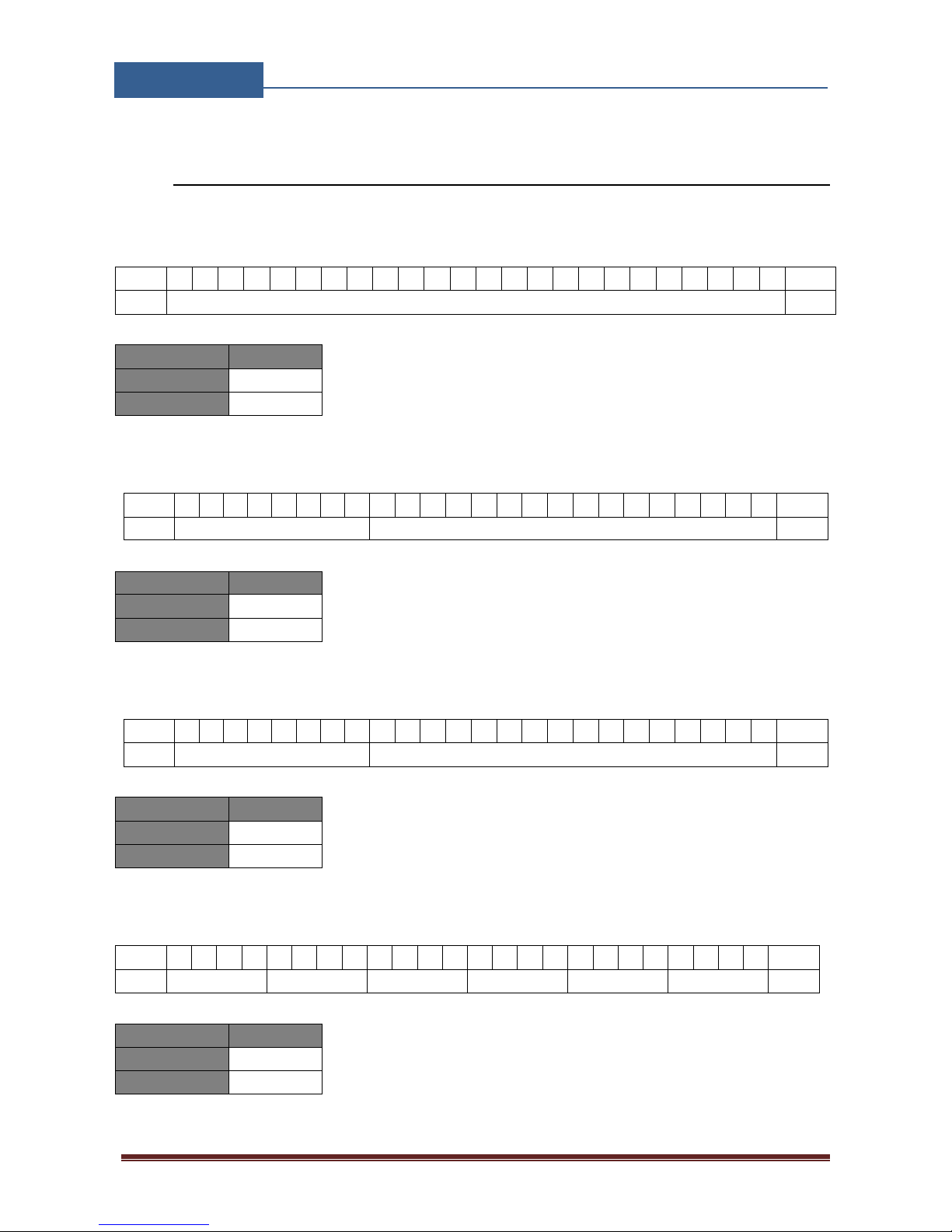
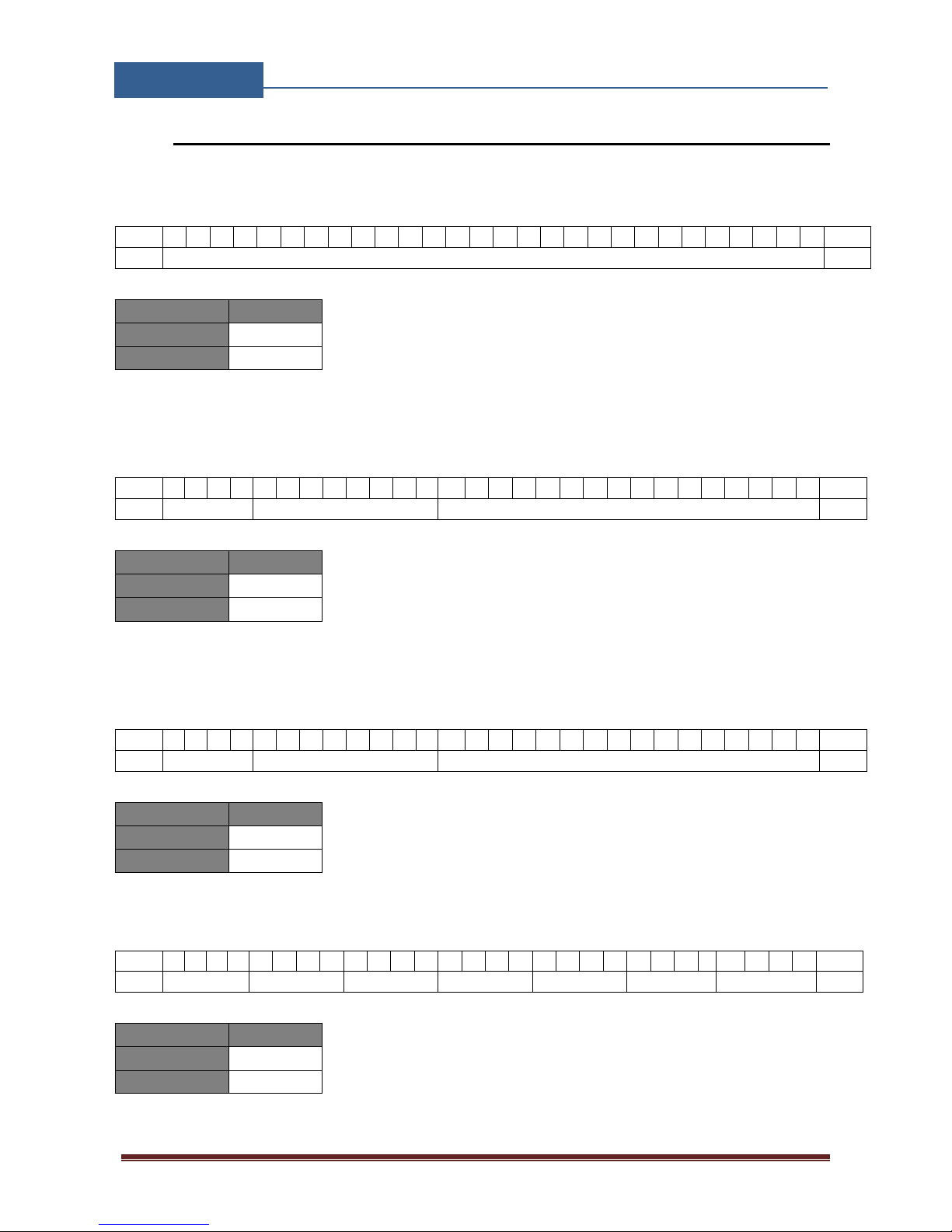
10.2 WIEGAND 26 BIT, DIFFERENT DATA FORMATS
Possible data format:
Mode 0: All 24bit of data are used a decimal representation, no option for facility code
P B B B B B B B B B B B B B B B B B B B B B B B B
P
Parity
24Bit card number
Parity
Limits
Card Number
0 - 16777215
Facility Number
None
Table 1: Wiegand 26: Mode 0.
Mode 1: 24bit of data is divided between facility code 8 bits and 16bits for card number
P F F F F F F F F B B B B B B B B B B B B B B B B
P
Parity
8Bit card facility number
16Bit card number
Parity
Limits
Card Number
0 - 16777215
Facility Number
NOT USED
Table 2: Wiegand 26: Mode 1.
Mode 2: 24bit of data is divided between facility code 8 bits and 16bits for card number
P F F F F F F F F B B B B B B B B B B B B B B B B
P
Parity
8Bit card facility number
16Bit card number
Parity
Limits
Card Number
0 - 16777215
Facility Number
0 - 255
Table 3: Wiegand 26: Mode 2.
Mode 3: Sections of 4bit data are used as decimals values for number
P B B B B B B B B B B B B B B B B B B B B B B B B
P
Parity
Dec. 6
Dec. 5
Dec. 4
Dec. 3
Dec. 2
Dec. 1
Parity
Limits
Card Number
0 - 99999
Facility Number
None
Table 4: Wiegand 26: Mode 3.
Page 40
EIS-LCD,!EIS-40!
USER!MANUAL!
Page%39%
10.3 WIEGAND 30 BIT, DIFFERENT DATA FORMATS
Possible data format:
Mode 0: All 30bit of data are used a decimal representation, no option for facility code
P B B B B B B B B B B B B B B B B B B B B B B B B B B B B
P
Parity
28Bit card number
Parity
Limits
Card Number
0 - 268435455
Facility Number
None
Table 5: Wiegand 30: Mode 0.
Mode 1: 30bit of data is divided between facility code 8 bits, 16bits for card number and 4bits of
unused data.
P 0 0 0 0 F F F F F F F F B B B B B B B B B B B B B B B B
P
Parity
Not used
8Bit facility number
16Bit card number
Parity
Limits
Card Number
0 - 16777215
Facility Number
NOT USED
Table 6: Wiegand 30: Mode 1.
Mode 2: 28bit of data is divided between facility code 8 bits, 16bits for card number and 4bits of
unused data.
P 0 0 0 0 F F F F F F F F B B B B B B B B B B B B B B B B
P
Parity
Not used
8Bit facility number
16Bit card number
Parity
Limits
Card Number
0 - 16777215
Facility Number
0 - 255
Table 7: Wiegand 30: Mode 2.
Mode 3: Sections of 4bit data are used as decimals values for number
P 0 0 0 0 B B B B B B B B B B B B B B B B B B B B B B B B
P
Parity
Not Used
Dec. 6
Dec. 5
Dec. 4
Dec. 3
Dec. 2
Dec. 1
Parity
Limits
Card Number
0 - 99999
Facility Number
None
Table 8: Wiegand 30: Mode 3.
Page 41
EIS-LCD,!EIS-40!
USER!MANUAL!
Page%40%
10.4 ALARM INPUTS
Units addressed: -EIS-1, EIS-2, EIS-4, EIS-R, EIS-LCD, EIS-40
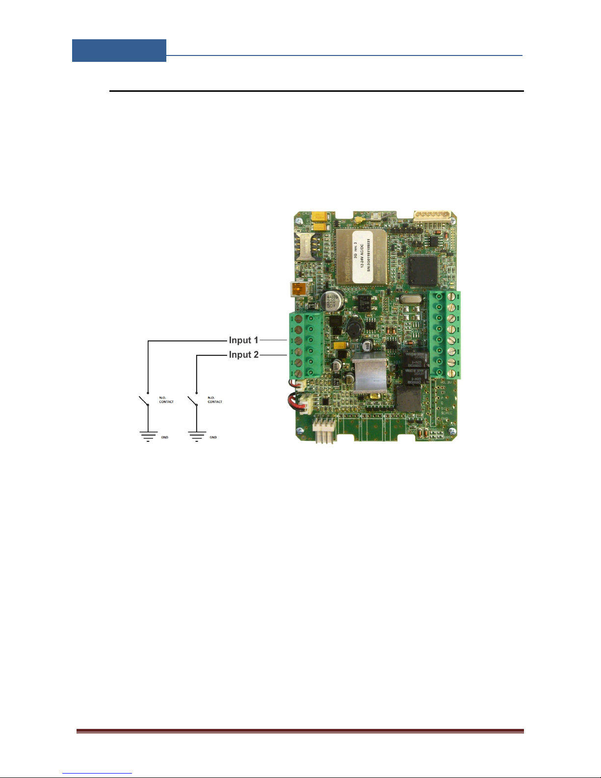
EIS units can be used for notification purposes if additional sensors are connected to the alarm
inputs of the unit. Active status on the sensor will result in notification SMS send to the numbers
defined.
Figure 28: Alarm inputs: Connection diagram.
Configuration of the alarm activity is done in 2 steps.
User must first define the settings in the Input tab.
Page 42
EIS-LCD,!EIS-40!
USER!MANUAL!
Page%41%
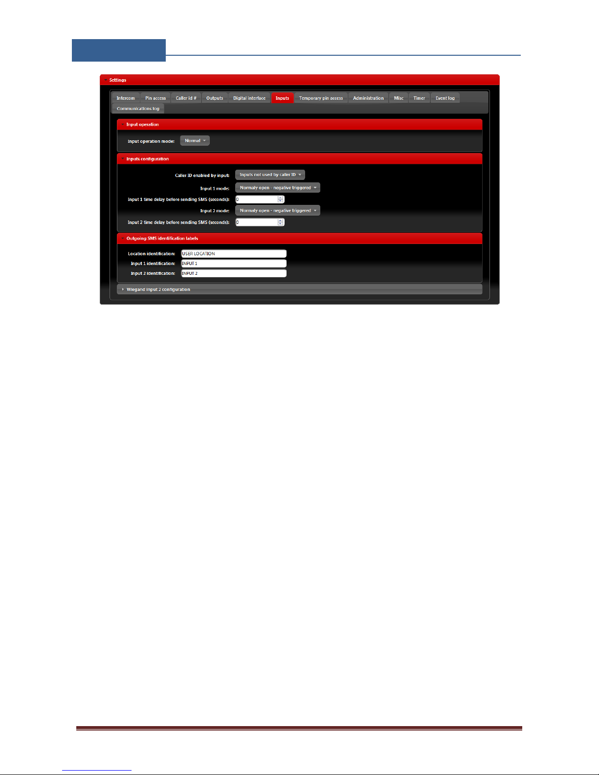
Figure 29: Alarm inputs: Inputs tab configuration.
• Input operation mode: Alarm inputs and 2. Wiegand interface lines are multiplex, to use it
alarm input mode, select Normal setting.
• Input 1 mode: User can select between different options of the input sensor configuration.
• Input 1 timer delay before sending SMS (seconds): Minimum time for a valid ACTIVE
status on the input. Signal levels below this time are disregarded.
• Input 2 mode: User can select between different options of the input sensor configuration.
• Input 2 timer delay before sending SMS (seconds): Minimum time for a valid ACTIVE
status on the input. Signal levels below this time are disregarded.
• Location identification: Text used in the SMS header send to the user in case of activity on
alarm inputs.
• Input 1 identification: Text used in the SMS sub header send to the user in case of activity
on 1 alarm input.
• Input 2 identification: Text used in the SMS sub header send to the user in case of activity
on 2 alarm input.
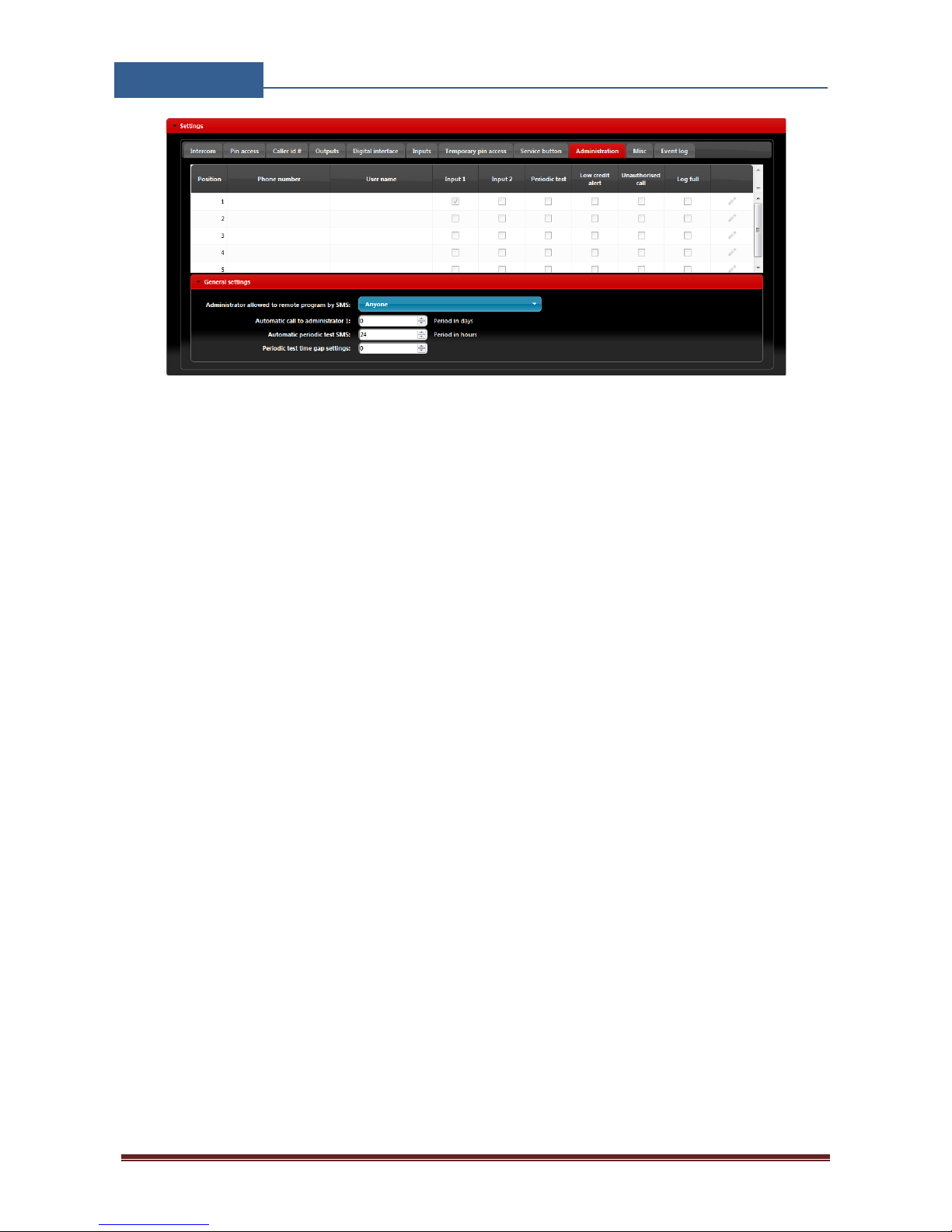
In second step the user must defined the numbers that will receive the alarm SMS. Multiple choices
are valid.
Page 43
EIS-LCD,!EIS-40!
USER!MANUAL!
Page%42%
Figure 30: Alarm inputs: Administration tab configuration.
• Phone number, User name: Phone number and user name of the user that will be receiving
notification messages.
• Input1, Input2: If alarm condition is meet, users with check boxes will receive alarm
notification SMS.
Page 44

TRANSMITTER SOLUTIONS WARRANTY
The warranty period of this Transmitter Solutions product is twenty-four (24) months. This warranty shall
begin on the date the product is manufactured. During the warranty period, the product will be repaired or
replaced (at the sole discretion of Transmitter Solutions) if the product does not operate correctly due to a
defective component. This warranty does not extend to (a) the product case, which can be damaged by
conditions outside the control of Transmitter Solutions, or (b) battery life of the product. This warranty is
further limited by the following disclaimer of warranty and liability:
EXCEPT AS SET FORTH ABOVE, TRANSMITTER SOLUTIONS MAKES NO WARRANTIES REGARDING THE GOODS, EXPRESS OR
IMPLIED, INCLUDING WARRANTY OF MERCHANTABILITY OR WARRANTY OF FITNESS FOR A PARTICULAR PURPOSE. BUYER
MAKES NO RELIANCE ON ANY REPRESENTATION OF TRANSMITTER SOLUTIONS, EXPRESS OR IMPLIED, WITH REGARD TO
THE GOODS AND ACCEPTS THEM “AS-IS/WHERE-IS”. TRANSMITTER SOLUTIONS SELLS THE GOODS TO BUYER ON
CONDITION THAT TRANSMITTER SOLUTIONS WILL HAVE NO LIABILITY OF ANY KIND AS A RESULT OF THE SALE. BUYER
AGREES THAT TRANSMITTER SOLUTIONS SHALL HAVE NO LIABILITY FOR DAMAGES OF ANY KIND, WHETHER DIRECT,
INCIDENTAL OR CONSEQUENTIAL DAMAGES, INCLUDING INJURIES TO PERSONS OR PROPERTY, TO BUYER, ITS
EMPLOYEES OR AGENTS, AS A RESULT OF THE SALE. BUYER ALSO AGREES TO HOLD TRANSMITTER SOLUTIONS
HARMLESS FROM ANY CLAIMS BUYER, OR ANY THIRD PARTY, MAY HAVE AS A RESULT OF BUYER’S USE OR DISPOSAL OF
THE GOODS. BUYER HAS READ THIS DISCLAIMER AND AGREES WITH ITS TERMS IN CONSIDERATION OF RECEIVING THE
GOODS.
2480 SOUTH 3850 WEST, SUITE B
SALT LAKE CITY, UT 84120
(866) 975-0101 • (866) 975-0404 FAX
WWW.TRANSMITTERSOLUTIONS.COM
 Loading...