

Page 1
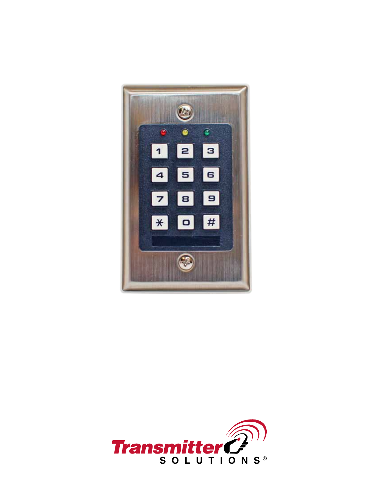
SELF CONTAINED
DIGITAL ACCESS CONTROL KEYPAD
WITH WIEGAND OUTPUT & DATA I/O
Programming & Installation Manual
FOR ELECTRIC LOCK INSTALLATION
DOLKSS1KB
Page 2
DOLKSS1KB
RED
Programming and installation manual
INTRODUCTION
DOLKSS1KB is a universal digital access keypad that offers reliability and cost-effective solutions
for residential and commercial installations. It is designed for a stand-alone electric lock that
operates from a 12V-24V AC/DC power supply. It is virtually compatible with any electric
locking device.
DOLKSS1KB features two settings: Single User Mode, which grants a single 4-digit code for
access and Multi-User Mode, which grants up to 100 unique 4-8 digit codes for access. The
DOLKSS1KB also has a feature to temporarily lock all access to users until unlocked. The
memory stored in the DOLKSS1KB will not be erased in the event of a power failure.
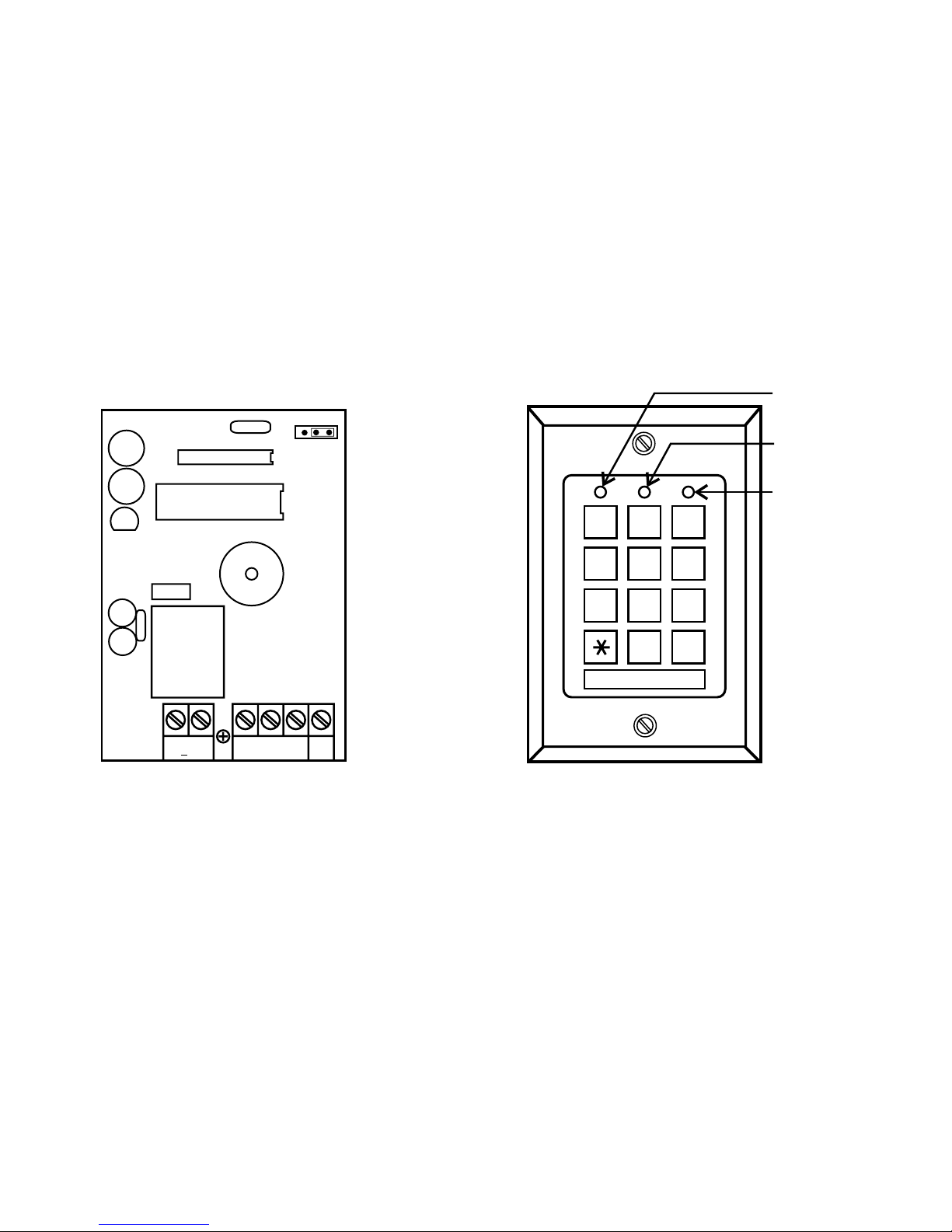
CONNECTION TERMINALS
DOLKSS1B
DAP
ON OFF
AMBER
GREEN
3
5
6
89
0
#
RELAY
+ -
12 24V
OUTPUT 1
N.C. C. N.O.
EG
12
4
7
DOLKSS1B
IN
· 12V-24V AC/DC (Power input)
· Connect 12V-24V AC/DC power. The (-) is the common ground.
· Output 1 (Relay Output)
· N.C. (Normally closed)
· Use N.C. for equipment that requires a constant flow of electricity to function
properly. Ex. Magnetic locks, receivers, etc.
· COM (Common ground)
· N.O. (Normally open)
· Use N.O. for equipment that requires a temporary surge of electricity to activate. Ex.
Electric door locks, automated gates, etc.
· EG. IN (Egress input)
· The optional EG. IN is commonly connected to buttons. Buttons that are connected to
EG. IN will grant access when pressed.
· LED Indicators
· Red
· The red LED indicates if the “Access Lock” is activated. This feature temporarily
denies all access to users until reauthorized. Refer to the Access Lock section for
Page 3
more details.
· Yellow
· It flashes on Standby. The Yellow LED also indicates the system’s status in
synchronization with the tones.
· Green
· This LED indicates a successful access.
· DAP Jumper
· Used to access Programming Mode without using the Master Code
THE DAP JUMPER (DIRECT ACCESS TO PROGRAMMING)
If the master code is forgotten, use the DAP jumper to reset the DOLKSS1KB into programming
mode. DAP can be accessed with the following procedure:
1. Disconnect the power supply.
2. Switch the DAP jumper from off to on.
3. Reconnect the power supply (the buzzer will activate).
4. Switch the DAP jumper back to the off position.
5. The keypad is in programming mode and ready to receive new programming data.
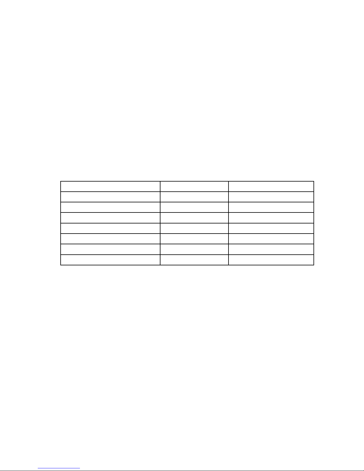
KEYPAD TONES AND THE LED SIGNALS
STATUS TONES LED SIGNALS
1. In programming mode Solid Yellow
2. Successful key entry 1 Beep 1 Flash
3. Successful code entry 2 Beeps 2 Flashes
4. Unsuccessful code entry 5 Beeps 5 Flashes
5. DAP jumper not replaced Continuous Beeps Continuous Flashes
6. Standby mode 1 flash every 2 seconds
7. Output relay activated 1-second Beep
THE FACTORY-SET MASTER CODE
If programming the DOLKSS1KB for the first time, the default master code is 0000. Refer to the
programming chart to set a new master code.
SINGLE USER MODE AND MULTI-USER MODE
The DOLKSS1KB features two settings: Single User Mode, which grants a single 4-digit code for
access and Multi-User Mode, which grants up to 100 unique 4-8 digit codes for access.
· Single User Mode
Single User Mode will grant access for a single 4-digit code. This mode will not require the
user to press the # key after code entry.
· Multi-User Mode
Multi-User Mode will grant access for up to 100 unique 4-8 digit codes. The user codes will
require a # key after code input.
The Multi-User Mode Limitation
The first digit of each user code cannot be +2 or -2 of a stored user code. For example, if
User Code: 5678 was stored in the system, User Code: 3678 and 7678 are not allowed.
Page 4
IMPORTANT NOTES FOR SWITCHING BETWEEN SINGLE USER MODE AND MULTI-
USER MODE:
· Switching between Single User mode and Multi-User Mode will reset all data for the
DOLKSS1KB except the master code.
· Be sure the User Code, Authorization Code, and Master Code are 4-digits for Single
User Mode. Code entry will not be accepted otherwise.
· It is necessary to change the Master Code to 4-digits before switching from Multi-User
Mode to Single User Mode.
· The system takes 2 to 3 seconds to switch between modes. During its switch, do not
press any buttons until the 2 confirmation beeps are heard.
ACCESS LOCK
Access Lock is an optional feature of the DOLKSS1KB. An authorization code can be set-up to
control access. The authorization code will lock all access to all users until unlocked. When
Access Lock is activated, the red LED will remain on.
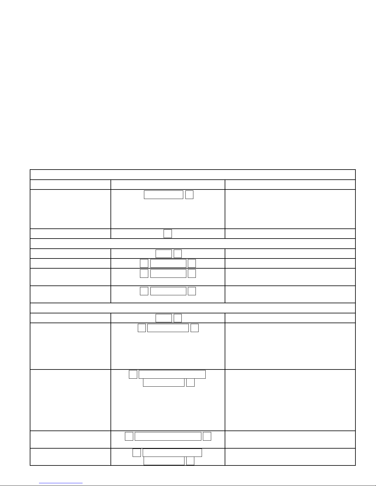
PROGRAMMING CHART
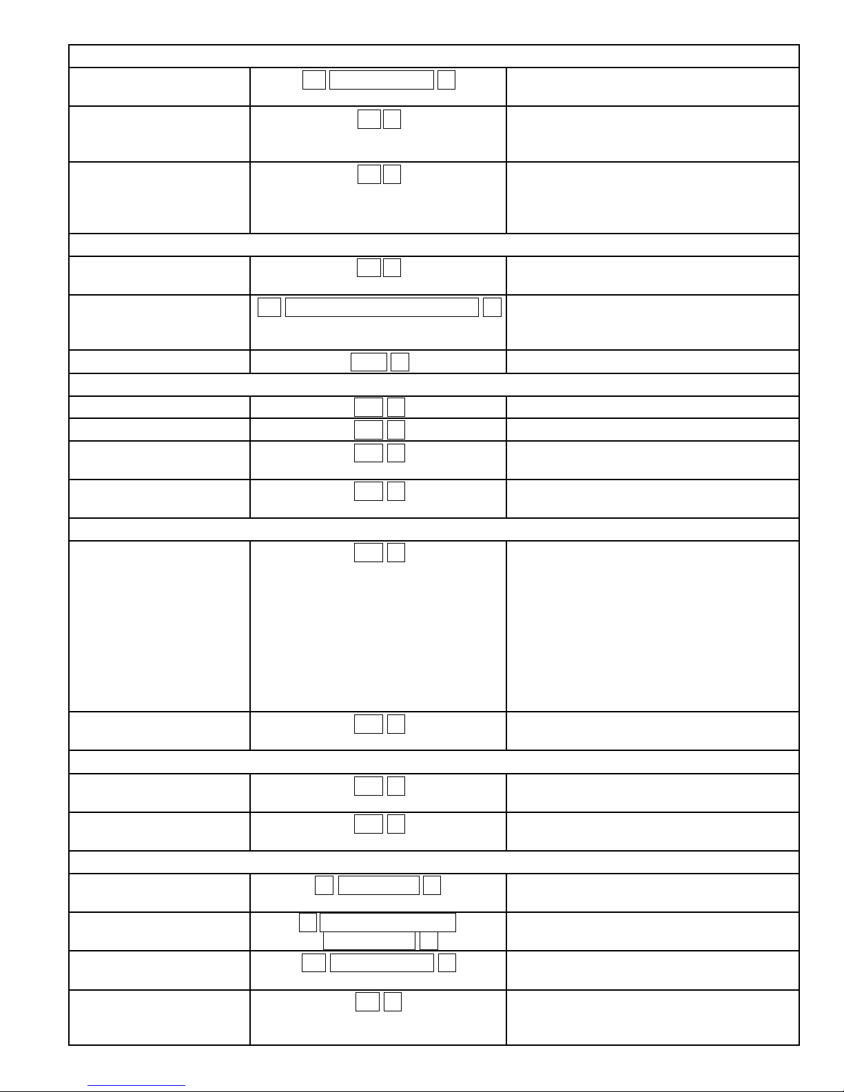
DOLKSS1KB
Keypad Feature Code Entry Comments
Begin Programming
Mode (Solid Yellow)
Master Code * Set System into Programming Mode. The
default Master Code is 0000.
Note: All of the following commands must
be keyed while in Programming Mode.
End Programming Mode * Return to normal operation.
Single User Mode
Single User Mode 8900 # Set to Single User Mode and clear all data
Set Master Code 0 4-digit code # Set your new Master Code.
Add User Code for
general access
Set optional Authorization
Code for Access Lock
1 4-digit code # Set 4-digit code for general access.
2 4-digit code # Set 4-digit code for Access Lock activation.
Multi-User Mode
Multi-User Mode 8901 # Set to Multi User Mode and clear all data
Set Personal Master Code 0 4-8 digit code # Set your new Master Code.
Important Note: It is necessary to change
the Master Code to 4-digits before
switching from Multi-User Mode to Single
User Mode.
Add Access Code for up
to 100 different users.
1 User number: 00 to 99
4-8 digit code #
Set 4-8 digit code for general access. Each
unique 4-8 digit code will require a new
user number.
Delete User 1 User number: 00 to 99 # Deletes the user and removes their Access
Set optional Authorization
Code for Access Lock
2 User number: 0 to 9
4-8 digit code #
Important Note: It is important to
document your user numbers because
users can be deleted and reassigned new
codes for access.
Code
Set 4-8 digit code for Access Lock
activation.
Page 5
Lock Settings
Set door unlock timer 40 Seconds: 1-999 # Set the amount of seconds the device will
grant access before locking again.
Set Access Code to toggle
[open/close]
Set Access Code to toggle
[open/close] (partial
entry)
41 # Entering Access Code will toggle the lock
to stay open. Entering the Access Code
again will toggle back to lock.
42 # Entering [The first 2 digits of an access
code, #] will toggle lock to remain open
and entering the full access code will
toggle back to close.
Safety Settings
Default safety setting 70 # After 10 successive false codes, the keypad
is disabled for 30 seconds
Extended safety settings 72 Number of false entries: 5-10 # After [5-10] successive false code entries,
the keypad is disabled for 15 minutes or
until the Master Code is entered.
Disable all safety settings 7600 #
Sound Settings
All sounds - On 831 # All sounds will be activated
All sounds - Off 830 # All sounds will be disabled
Access sound - 1 second
buzz
Access sound - 2 short
beeps
811 # Upon unlocking, the keypad will signal
granted access with a 1-second buzz
810 # Upon unlocking, the keypad will signal
granted access with 2 short beeps
Auto/Manual Code Entry Settings
Auto Code Entry Mode 821 # The # key after entering an access code
will NOT be required.
Important Note: For this feature to work
with Multi-User Mode, the Master Code
and Access Codes must be the same
number of digits. Ex. If the Master Code is
6-digits, then the Access Codes must also
be 6-digits to have the Auto Code Entry
Mode to work.
Manual Code Entry Mode 820 # The # key after entering an access code
will be required
Flashing Yellow LED Settings
Flashing Yellow LED - On 841 # The Yellow LED will blink every 2 seconds
during functionality
Flashing Yellow LED - Off 840 # The Yellow LED will not blink during
functionality
Access Lock (Optional)
Set Authorization Code
(Single User Mode)
Set Authorization Code
(Multi-User Mode)
Set Access Lock timer 50 Seconds: 1-999 # Set the amount of seconds Access Lock
Set Authorization Code to
toggle [on/off]
2 4-digit code # Set 4-digit code for Access Lock activation.
2 User number: 0 to 9
4-8 digit code #
51 # Entering Authorization Code will toggle
Set 4-8 digit code for Access Lock
activation.
will activate before deactivating
Access Lock on. Entering the Authorization
Code again will toggle Access Lock off.
Page 6
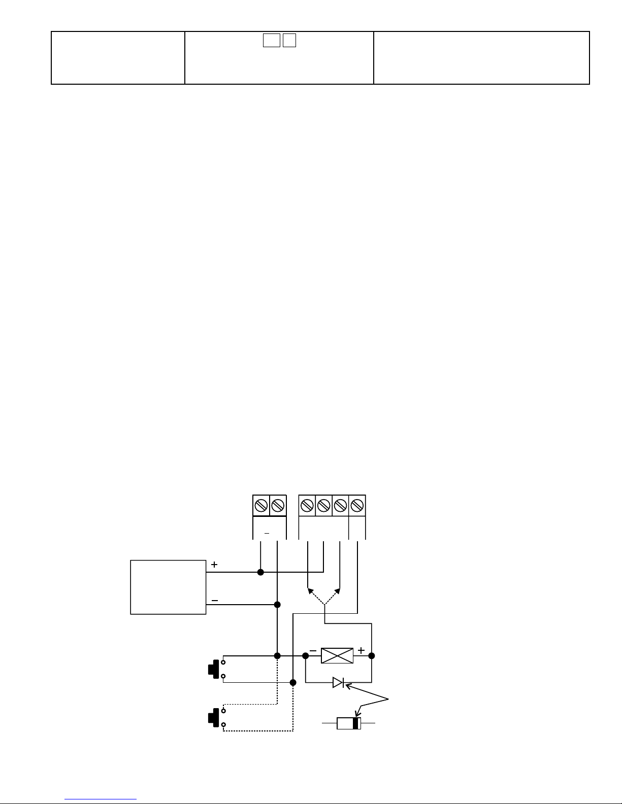
Set Authorization Code
to toggle [on/off] (partial
entry)
52 # Entering [The first 2 digits of an
Authorization Code, #] will toggle Access
Lock on and entering the full Authorization
Code will toggle Access Lock to off.
SPECIFICATIONS
Operation Voltage:
12V-24V AC/DC, No jumper is required for voltage selection
Operation Modes:
Single User Mode, Auto, or Manual Code Entry
Multi-User Mode, Auto, or Manual Code Entry
User Code Combinations:
Single User Mode: 10,000
Multi User Mode: 111,110,000
Multi User Mode: 100 user codes for door open (User number: 00-99)
Access Lock Mode: 10 user codes for Access Lock codes (User number: 0-9)
Egress input:
Normally open
Relay Output Contacts:
Normally Closed and Normally Open Dry Contacts, 5A / 30VDC Max. Rating
Auto Refreshing Time During Code Entry:
Each digit maximum entry time limit – 10 seconds
Each code maximum entry time limit – 30 seconds
Dimensions: 4 5/8(H)” x 2 7/8(W)” X 1 7/8(D)”
Weight: 5.5oz net
Specifications are subject to change for modification without notice
BASIC WIRING EXAMPLE – Basic wiring of a stand-alone door lock
-
12 24V
AC/DC
POWER
SUPPLY
AD-1312
AD-2312
OR AP-960
EGRESS BUTTON
(INSIDE THE HOUSE)
MORE EGRESS
BUTTONS CAN
BE CONNECTED
IN PARALLEL
N.O.
N.O.
+ -
12 24V
OUTPUT 1
N.C. C. N.O.
N.C. N.O.
OR
ELECTRICLOCK
1N4004
EG
IN
OUTPUTRELAY
N.O. Output for Fail-secure Lock
N.C. Outputfor Fail-safe Lock
CATHODE
Page 7
Note:
· Connect 1N4004 as close as possible to the lock parallel with the lock power terminals
to absorb the back EMF and prevent keypad damage. The 1N4004 is not required for
AC power.
· To avoid electrostatic discharge from interfering with the keypad, always ground the
terminal.
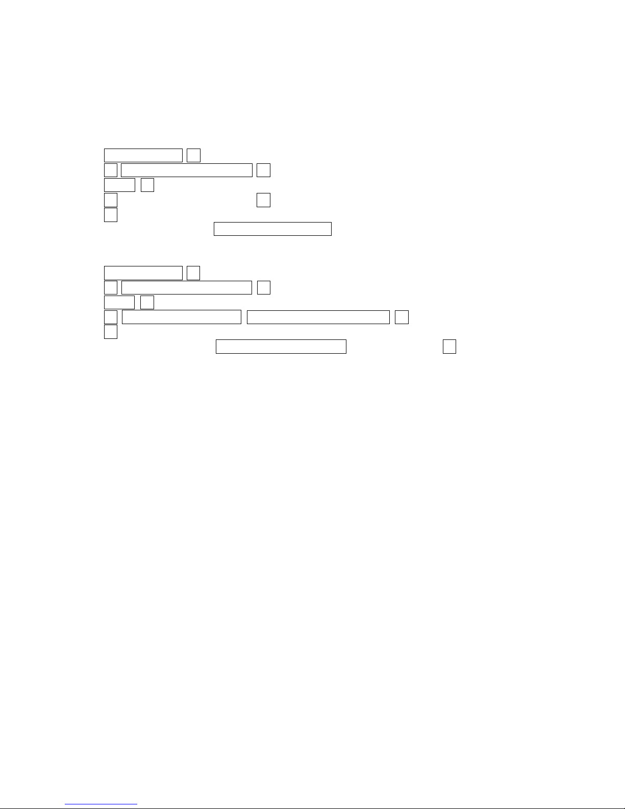
Quick Programming Guide (Simple) - Single code access
1. Enter: Master Code * (Default [Master Code]: 0000)
2. Enter: 0 Master Code (4 digits) #
3. Enter: 8900 #
4. Enter: 1 Access Code (4 digits) #
5. Enter: *
6. To gain access: Enter the 4-digit Access Code
Quick Programming Guide (Advanced) – Multi-code access
1. Enter: Master Code * (Default Master Code: 0000)
2. Enter: 0 Master Code (4 digits) #
3. Enter: 8901 #
4. Enter: 1 User Number: 00-99 Access Code (4-8 digits) #
5. Enter: *
6. To gain access: Enter the 4-8 digit Access Code followed by the # key.
Refer to the DOLKSS1KB manual for additional programming options.
TRANSMITTER SOLUTIONS WARRANTY
The warranty period of this product is 12 months from the purchasing date. During this period,
if the product does not operate correctly due to a defective component, the product will be
repaired or replaced at the sole discretion of Transmitter Solutions. This warranty does not
extend to the product’s casing, which can be damaged by conditions outside of the control of
Transmitter Solutions.
Page 8

7380 S. Eastern Ave, Suite 124-320 • Las Vegas, NV 89123
(866) 975-0101 • (866) 975-0404 fax
www.transmittersolutions.com
 Loading...