

Page 1
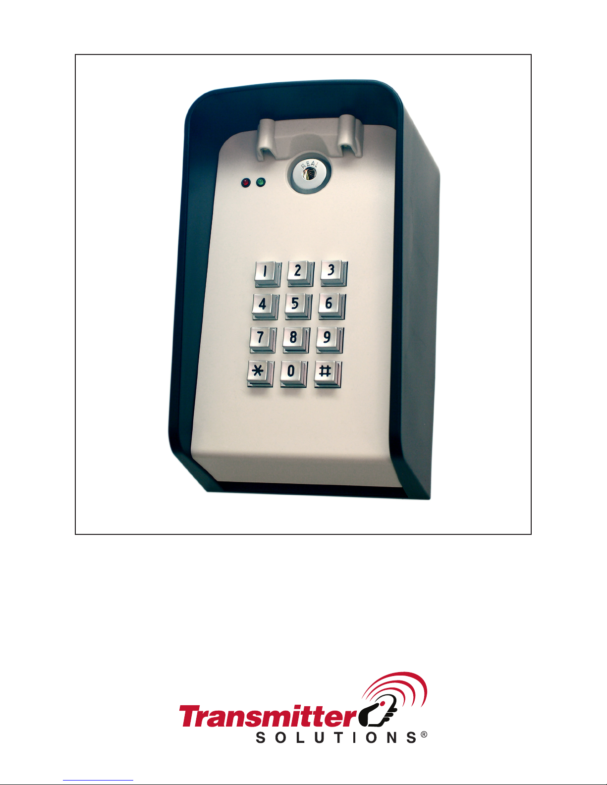
Programming & Installation Manual
DOL1000-MF
Page 2

Page 3
INTRODUCTION
The DOL1000-MF is a versatile keypad that has the option of running wirelessly. The DOL1000-MF
can work with 6 volts of battery power or 6-24 volts of AC/DC. This keypad can be wired with multiple
wireless transmitters. DOL1000-MF can store up to 1000 access codes. Guest access codes are also
programmable, which are single-use codes for access. After 5 successive incorrect codes, the
keypad will lock for 4 minutes
PROGRAMMING CHART: DOL1000-MF
Default Master Code: 1 2 3 4
1 2 3 4, 1#, Access Code: __ __ __ __ , Channel:1-4, #
Add Access
Codes
Remove Access
Codes
Add Guest
Code
Add Access
Toggle Code
Set Relay
Output Time
Use Channel 1 if unsure. The different channels are dependent on the RF
terminal used. Any channel can be assigned for devices that connect to normally
open/normally closed.
1 2 3 4, 2#, Access Code: __ __ __ __ , #
Enter the Access Code you would like to delete.
1 2 3 4, 3#, Guest Code: __ __ __ __ , Channel:1-4
The Guest Code is a one-time use access code. Once used, the number will be
cleared from memory.
1 2 3 4, 4#, Toggle Code: __ __ __ __ , Channel:1-4
Entering Access Toggle Code will toggle the keypad to continuously activate.
Entering the code again will toggle the keypad off. Dip switch #6 on the circuit
board needs to be in the off position in order for this mode to work.
1 2 3 4, 5#, Seconds:0-60, #
Set the number of seconds the device will grant access before locking again.
Change Master
1 2 3 4, 7#, Master Code: __ __ __ __ , #
Code
Changes Master Code. If the Master Code is forgotten, this manual contains
instructions on how to reset the Master Code.
1 2 3 4, 8#
Clear All Codes
This will clear all data except the Master Code.
To clear an entry, press *
Page 4

CONNECTION TERMINALS
• V+/V-: These terminals will supply power to the transmitter.
• ANT: Antenna
• RF1-4: The DOL1000-MF can control up to 4 different channels. Each RF terminal represents
a different channel.
• GO: Connects to the green LED
• NOGO: Connects to the red LED
• KEYPADUTE: Connects to the DOL1000-MF lights located in front of the keypad
• NO (Normally open): Use N.O. for equipment that requires a temporary surge of electricity to
activate. Example, Electric door locks, automated gates, push plates, etc.
• COM: Common ground
• NC (Normally closed): Use N.C. for equipment that requires a constant flow of electricity to
function properly. Example, Magnetic locks, receivers, etc.
• BATTERY 6VDC: If deciding to power the DOL1000-MF with a battery, then connect the
battery to these terminals.
• 6-24VAC/DC: If deciding to hardwire the DOL1000-MF directly to a power source, use these
terminals.
• Master Reset Button: Holding this button down for 5 seconds after reconnecting the keypad
to its power source will make the keypad beep 3 times. This will indicate that the Master Code
has been reset to 1234.
DIP SWITCHES
1. SOUND
2. LED
3. LIGHTS
4. Not used
5. Not used
6. WIRELESS MODE
a. Switching this dip switch to off will enable the toggle gate feature and switching to the
on position will disable the toggle gate feature. Disabling this feature can potentially
save battery power in the case that the toggle gate feature has been accidentally
activated. Refer to the programming chart for more details with the toggle gate feature.
7. Not used
8. Not used
Page 5
RESETTING THE KEYPAD AND MASTER CODE
Located on the DOL1000-MF’s circuit board, the red Master Reset Button is used to reset the master
code back to 1234. The following steps will reset the master code:
1. Remove the battery or eliminate the power source to the DOL1000-MF and wait for 30
seconds for the keypad to completely power off.
2. Press and hold the red Master Reset Button.
3. While holding the red Master Reset Button, reconnect the battery or power source to the
DOL1000-MF.
4. Continue to hold the red Master Reset Button until the keypad beeps 3 times. This will indicate
that the Master Code has been reset to 1234.
INSTALLATION EXAMPLES
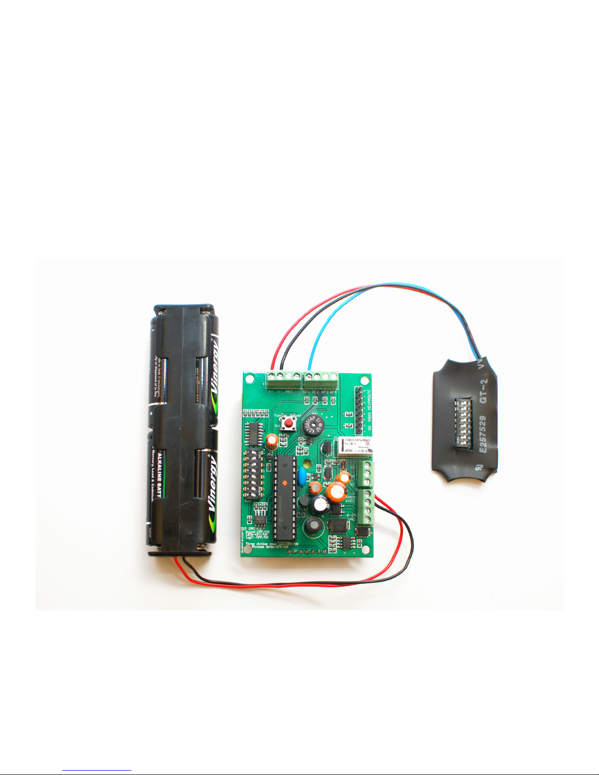
Dip switch with battery example:
• NOTE: Be sure to connect the power source to the correct terminals! The battery terminals
and the AC/DC terminals are different.
Page 6
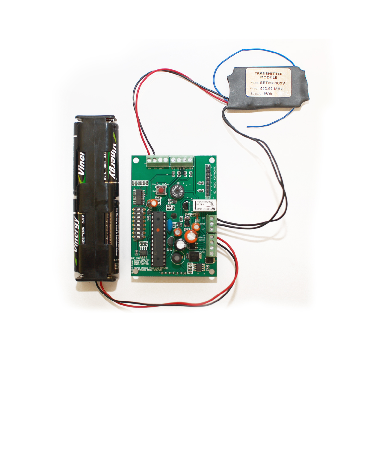
• 433MHz transmitter with battery example:
• NOTE: Be sure to connect the power source to the correct terminals! The battery terminals
and the AC/DC terminals are different.
• NOTE: Any channel can be assigned for devices that connect to normally open/normally
closed.
Page 7

TRANSMITTER SOLUTIONS WARRANTY
The warranty period of Transmitter Solutions keypad is twenty-four (24) months. This warranty shall
begin on the date the keypad is manufactured. During the warranty period, the product will be
repaired or replaced (at the sole discretion of Transmitter Solutions) if the product does not operate
correctly due to a defective component. This warranty does not extend to (a) the keypad case,
which can be damaged by conditions outside the control of Transmitter Solutions, or (b) battery life
of the keypad. This warranty is further limited by the following disclaimer of warranty and liability:
EXCEPT AS SET FORTH ABOVE, TRANSMITTER SOLUTIONS MAKES NO WARRANTIES
REGARDING THE GOODS, EXPRESS OR IMPLIED, INCLUDING WARRANTY OF
MERCHANTABILITY OR WARRANTY OF FITNESS FOR A PARTICULAR PURPOSE. BUYER MAKES
NO RELIANCE ON ANY REPRESENTATION OF TRANSMITTER SOLUTIONS, EXPRESS OR
IMPLIED, WITH REGARD TO THE GOODS AND ACCEPTS THEM “AS-IS/WHERE-IS”.
TRANSMITTER SOLUTIONS SELLS THE GOODS TO BUYER ON CONDITION THAT TRANSMITTER
SOLUTIONS WILL HAVE NO LIABILITY OF ANY KIND AS A RESULT OF THE SALE. BUYER
AGREES THAT TRANSMITTER SOLUTIONS SHALL HAVE NO LIABILITY FOR DAMAGES OF ANY
KIND, WHETHER DIRECT, INCIDENTAL OR CONSEQUENTIAL DAMAGES, INCLUDING INJURIES
TO PERSONS OR PROPERTY, TO BUYER, ITS EMPLOYEES OR AGENTS, AS A RESULT OF THE
SALE. BUYER ALSO AGREES TO HOLD TRANSMITTER SOLUTIONS HARMLESS FROM ANY
CLAIMS BUYER, OR ANY THIRD PARTY, MAY HAVE AS A RESULT OF BUYER’S USE OR
DISPOSAL OF THE GOODS. BUYER HAS READ THIS DISCLAIMER AND AGREES WITH ITS TERMS
IN CONSIDERATION OF RECEIVING THE GOODS.
SPECIFICATIONS
IP Rating: IP64
Temperature Rating: -40C to 70C / -40F to 158F
Size: 7 1/2in. x 7 3/4in. x 3 5/8in.
Weight: 1 ¾ lbs.
Housing: ABS
Face Plate Material: ABS
Operating Voltage: 6-24 AC/DC
Output relays: 1A
Page 8

7380 S. Eastern Ave, Suite 124-320 • Las Vegas, NV 89123
(866) 975-0101 • (866) 975-0404 fax
www.transmittersolutions.com
 Loading...