

Page 1

3000A Series
Precision Multi Product Calibrator
Operation Manual
Version 5.00: February 2011
All product names are trademarks of their respective companies
Page 2

3000A SERIES OPERATION MANUAL
IMPORTANT NOTICE
THIS CALIBRATOR
WILL
REQUIRE AN
UNLOCK CODE
AFTER THE EVALUATION
PERIOD HAS EXPIRED.
(60 Days after invoice date)
AFTER THE EVALUATION PERIOD HAS EXPIRED THE
OPERATION OF THE CALIBRATOR IS LOCKED AND THE DISPLAY
SHOWS A NUMBER WHICH MUST BE QUOTED TO TRANSMILLE
TO RECEIVE THE UNLOCK CODE
THE UNLOCK CODE IS AVAILALBLE
FROM TRANSMILLE
ONLY AFTER PAYMENT
HAS BEEN RECEIVED.
This code only needs to be entered once
in the life of the instrument.
Please contact Transmille or use the form in the
back of the manual to obtain the unlock code.
Transmille Ltd.
Staplehurst, Kent.
Tel: 44 (0)1580 890700 Fax: 44(0)1580 890711
Email: [email protected]
TRANSMILLE LTD. Version 5.00: February 2011 Page 2
Page 3
3000A SERIES OPERATION MANUAL
DECLARATION OF CONFORMITY
Manufacturer’s Name: Transmille Ltd.
Manufacturer’s Address: Unit 4, Select Business Centre
Lodge Road
Staplehurst
TN12 0QW
Declares, that the product
Product Name: Multi-product Calibrator
Model Number: 3050A / 3041A / 3010A
Product Options: This declaration covers all options of the above product(s)
Conforms with the following European Directives:
The product herewith complies with the requirements of the Low Voltage
Directive 73/73EEC and the EMC Directive 89/336/EEC (including 93/68/EEC)
and carries the CE Marking accordingly
Conforms with the following product standards:
EMC
EN 61326-1:1997+A1:1998 • EN55011:1991 (Group 1 : Class A)
Standard Limit
IEC 61000-4-2:1995+A1:1998 / EN 61000-4-2:1995 4kV CD, 8kV AD
IEC 61000-4-3:1995 / EN 61000-4-3:1995 3 V/m, 80-1000 MHz
IEC 61000-4-4:1995 / EN 61000-4-4:1995 0.5kV signal lines, 1kV power lines
IEC 61000-4-5:1995 / EN 61000-4-5:1995 0.5kV line-line, 1kV line-ground
IEC 61000-4-6:1996 / EN 61000-4-6:1996 3V, 0.15-80 MHz / cycle, 100%
IEC 61000-4-11:1994 / EN 61000-4-11:1994 Dips: 30% 10ms; 60% 100ms
Interrupt > 95%@5000ms
SAFETY
IEC 61010-1:1990+A1:1992+A2:1995 / EN 61010-1:1993+A2:1995
16/01/2006
Revision No: 1.0 Managing Director
Date: 16/01/2006
TRANSMILLE LTD. Version 5.00: February 2011 Page 3
Page 4

3000A SERIES OPERATION MANUAL
TABLE OF CONTENTS
3000A SERIES CALIBRATOR INTRODUCTION .................................................................................6
MAIN FEATURES ...................................................................................................................................6
ACCURACY AND FUNCTIONALITY............................................................................................................7
TRUE MULTIPRODUCT CALIBRATION FROM ONE INSTRUMENT ...................................................7
RETRO FIT OPTIONS ALLOWS ADDITIONAL FUNCTIONS TO BE ADDED. ...........................7
SERIAL LINE RS232 INTERFACE FITTED AS STANDARD..............................................................8
OUTPUT CONNECTION ..........................................................................................................................8
PREPARING THE CALIBRATOR FOR USE. .......................................................................................9
INITIAL INSPECTION. ..............................................................................................................................9
LIFTING AND CARRYING THE CALIBRATOR ..............................................................................................9
POSITIONING THE CALIBRATOR............................................................................................................10
REAR PANEL CONNECTIONS AND CONTROLS .......................................................................................11
SETTING AND CHECKING THE LINE VOLTAGE. .......................................................................................12
POWER LINE INLET FUSE AND RATING..................................................................................................12
CONNECTING TO A COMPUTER.............................................................................................................13
POWERING UP THE CALIBRATOR ..........................................................................................................13
OUTPUT CONNECTIONS ......................................................................................................................14
OUTPUT OVERLOADS..........................................................................................................................15
OPERATION ........................................................................................................................................16
SAFETY WARNINGS ............................................................................................................................16
INTRODUCTION TO OPERATION ............................................................................................................16
FRONT PANEL CONTROLS AND INDICATORS .........................................................................................17
FRONT PANEL KEYBOARD ...................................................................................................................17
FRONT PANEL KEYBOARD – CONTROL SECTIONS ................................................................................18
GRAPHIC LCD DISPLAY ......................................................................................................................19
DIGITAL CONTROL ..............................................................................................................................20
TERMINAL STATUS LED’S....................................................................................................................21
9 PIN ADAPTER INTERFACE CONNECTOR. ............................................................................................23
SETTING DC VOLTAGE AND CURRENT OUTPUT....................................................................................24
ADJUSTING THE SET OUTPUT USING THE DIGITAL CONTROL ...................................................................25
AUTOMATIC DISPLAY OF % OR PPM ERROR AND REF. KEY ...................................................................26
SETTING AC VOLTAGE AND CURRENT OUTPUT. ...................................................................................27
RETURNING THE CALIBRATOR TO DC ...................................................................................................28
SETTING 2 WIRE RESISTANCE OUTPUT. ..............................................................................................29
SETTING 2 WIRE SIMULATED RESISTANCE (OPTION)............................................................................31
SETTING 4 WIRE RESISTANCE OUTPUT. ..............................................................................................32
SETTING 4 WIRE RESISTANCE OUTPUT. ..............................................................................................32
USING CURRENT COILS (OPTION) .......................................................................................................34
SETTING CAPACITANCE OUTPUT. ........................................................................................................36
SETTING INDUCTANCE OUTPUT (OPTION) ............................................................................................37
THERMOCOUPLE SIMULATION (OPTION)...............................................................................................38
SPECIAL FUNCTIONS AVAILABLE USING THE ‘SOFT’ KEYS ......................................................................43
CONNECTING OUTPUT NEGATIVE TO LINE EARTH (GROUND)..................................................................43
SELECTING FRONT PANEL CONTROL.....................................................................................................43
SETTING TTL LOGIC FREQUENCY OUTPUT. .........................................................................................44
SETTING RPM OUTPUT WITH EA003 ADAPTOR (OPTION) ....................................................................45
SETTING PWM (MARK SPACE RATIO) .................................................................................................46
SELECTING PRT (PT100) RESISTANCE OUTPUT (OPTION) ..................................................................47
SELECTING SIMULATED PRT (RO) OUTPUT (OPTION)..........................................................................48
SELECTING AC POWER CALIBRATION OUTPUT (OPTION)......................................................................50
SELECTING DC POWER CALIBRATION OUTPUT (OPTION) .....................................................................53
SELECTING OSCILLOSCOPE CALIBRATION OUTPUT (OPTION)................................................................54
CALIBRATE .........................................................................................................................................56
SETUP (BEEPER / PASSWORD / ADAPTERS).........................................................................................56
TRANSMILLE LTD. Version 5.00: February 2011 Page 4
Page 5

3000A SERIES OPERATION MANUAL
WARNING AND OUTPUT OVERLOAD INDICATIONS. .................................................................................58
HIGH VOLTAGE TIMEOUT.....................................................................................................................58
30 AMP TEMPERATURE CUT-OUT ........................................................................................................58
INTERFACE TYPES ............................................................................................................................59
RS232 INTERFACE .............................................................................................................................60
USB INTERFACE.................................................................................................................................62
REMOTE PROGRAMMING .................................................................................................................63
PROGRAMMING COMMANDS OVERVIEW ...............................................................................................64
DC VOLTAGE COMMANDS...................................................................................................................66
AC VOLTAGE COMMANDS ...................................................................................................................68
DC CURRENT COMMANDS ..................................................................................................................70
AC CURRENT COMMANDS ..................................................................................................................72
RESISTANCE COMMANDS ....................................................................................................................74
CAPACITANCE COMMANDS ..................................................................................................................76
SIMULATED RESISTANCE COMMANDS (OPTION) ...................................................................................77
SIMULATED CAPACITANCE COMMANDS (OPTION) .................................................................................78
TTL FREQUENCY COMMANDS (OPTION) ..............................................................................................80
PULSE WIDTH MODULATION COMMANDS (OPTION) ..............................................................................82
INDUCTANCE COMMANDS (OPTION) .....................................................................................................84
PRT100 COMMANDS (OPTION)...........................................................................................................86
THERMOCOUPLE SIMULATION COMMANDS (OPTION) ............................................................................88
MISCELLANEOUS COMMANDS..............................................................................................................91
OSCILLOSCOPE CALIBRATION COMMANDS (OPTION) ............................................................................92
AC POWER CALIBRATION COMMANDS (OPTION) ................................................................................101
TECHNICAL DESCRIPTION..................................................................................................................104
GENERAL .........................................................................................................................................104
CONSTRUCTION................................................................................................................................105
INTERNAL FUSES ..............................................................................................................................106
OPENING THE CASE .........................................................................................................................107
ACCESS TO INTERNAL FUSES – TOP PCB..........................................................................................108
ACCESS TO INTERNAL FUSES – FRONT PANEL PCB...........................................................................109
POWER SUPPLY AND OUTPUT SWITCHING BOARD................................................................................110
PROCESSOR BOARD .........................................................................................................................110
MAIN ANALOGUE AMPLIFIER AND FEEDBACK BOARD ............................................................................111
HIGH VOLTAGE AMPLIFIER AND OUTPUT ............................................................................................112
CURRENT TRANSCONDUCTANCE AMPLIFIER.......................................................................................112
OUTPUT CURRENTS SENSING & SHUNTS...........................................................................................113
CALIBRATION TUTORIAL................................................................................................................114
GETTING THE BEST OUT OF THE CALIBRATOR. ....................................................................................114
CALIBRATION AND MAINTENANCE ..............................................................................................116
GENERAL .........................................................................................................................................116
ELECTRICAL SAFETY TESTS ..............................................................................................................116
CLEANING OF THE FAN DUCT ............................................................................................................117
CLEANING THE EXTERNAL CASE .........................................................................................................117
CALIBRATION....................................................................................................................................118
GUARANTEE AND SERVICE.................................................................................................................119
TRANSMILLE LTD. Version 5.00: February 2011 Page 5
Page 6
3000A SERIES OPERATION MANUAL
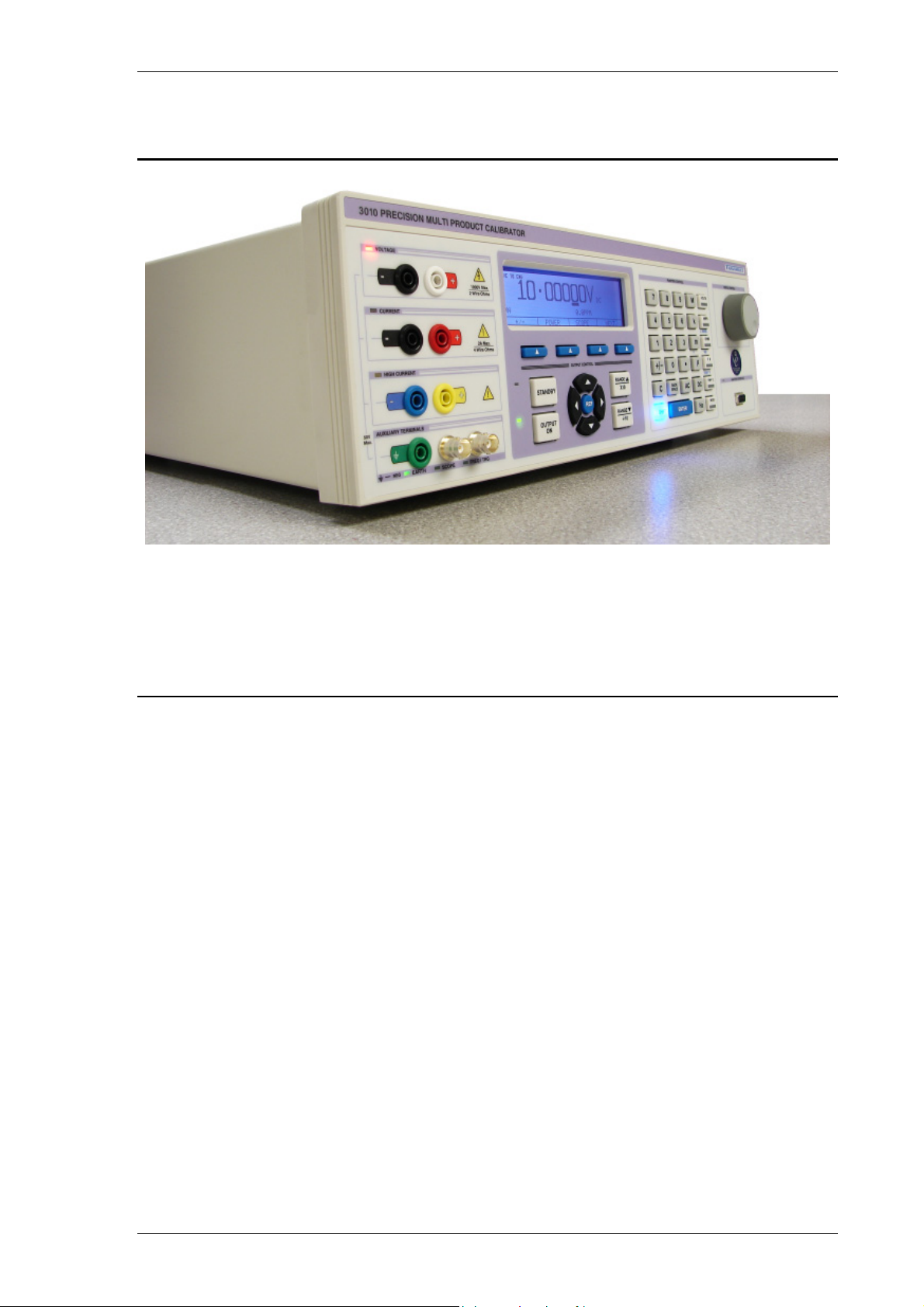
3000A Series Calibrator Introduction
The 3000A series of calibrators offer the smallest and by far the most portable multi
product multi-function calibrator in the world. The 3000A series calibrator provides a
fully functioned precision programmable calibration source.
Main Features
AC/DC Volts to 1025V
AC/DC Current to 30 Amps (20Amps for 3050A)
AC/DC Current to 1500 Amps with 50 Turn Clamp coil Adapter
2 and 4 Wire Resistance to 1GΩ (10 MΩ for 3050A)
Capacitance
Inductance (Option)
Logic Level Frequency
Mark Space Ratio
PT100 resistance Simulation (Option)
RTD Simulation active (Option)
Thermocouple Simulation (°C & °F)
DDS Power / Harmonics (Internal Option)
250/350/600MHz Oscilloscope Calibration (Internal Option)
RS232 Serial Interface GPIB (IEEE488) Interface Option
Extendable Range Of Adaptors via the Adapter Interface
TRANSMILLE LTD. Version 5.00: February 2011 Page 6
Page 7

3000A SERIES OPERATION MANUAL
Accuracy and Functionality
The 3000A Series calibrators are available in 3 accuracy grades, the 3010A basic
DC accuracy of 5ppm, the 3041A of 25ppm and the 3050A of 50ppm. The
appearance of the instruments is the same however the model type is indicated on
the front and rear panels and also shown on the display at switch on. The
calibrators are also available with reduced functions e.g. DC volts only etc.
True Multiproduct Calibration
From one instrument
Designed to provide an accurate cost effective portable instrument for the calibration
of multimeters, clamp meters, frequency meters, temperature meters, and
capacitance meters. Internal retro fit options allow the calibration of power meters,
oscilloscopes to 600MHz, inductance and LCR meters.
Designed for use in the laboratory or portable onsite calibration.
The 3000A series calibrator is suitable for use in the standards laboratory. The fast
warm up time combined with the small case and low weight make the 3000A series
calibrator also ideal for onsite calibration. The serial interface allows direct
connection to a PC/laptop.
Retro Fit Options
Allows additional functions to be added.
Several internal retro fit options including oscilloscope, power, inductance and PRT
allow the user to select the most cost effective solution for the calibration work with
the ability to add extra functions at a later date. External options for the calibration of
clamp meters, high accuracy thermocouple simulation with auto CJC (cold junction
compensation) built into the TC (thermocouple) connector, optical tachometers,
torque drivers etc. are also available via the front panel adapter interface.
TRANSMILLE LTD. Version 5.00: February 2011 Page 7
Page 8

3000A SERIES OPERATION MANUAL
Serial Line RS232 Interface
Fitted as standard.
All functions and outputs of the series 3000A calibrator are fully programmable over
the RS232 interface. The use of the RS232 interface saves the cost of fitting GPIB
cards to the PC, and also allows easy connection to portable PC’s, reducing the set
up time for on-site calibration.
Output Connection
The output terminal configuration is designed to match the majority of multimeter
input connections, e.g. volts/ohms, low current and high current eliminating the need
for lead changing during calibration. All outputs are isolated when not in use and an
L.E.D. indicator shows the active output(s).
TRANSMILLE LTD. Version 5.00: February 2011 Page 8
Page 9
3000A SERIES OPERATION MANUAL
Preparing The Calibrator For Use.
Initial inspection.
After shipment the calibrator should be inspected for any signs of external damage.
Should external damage be found contact the carrier immediately. Do not connect a
damaged instrument to the line power as this may result in internal damage. Please
retain the original packaging; this should be used when returning the calibrator for
service and recalibration.
Lifting and Carrying the Calibrator
The calibrator weighs 14.5kg with most of the weight at the right rear corner. The
calibrator can be carried by one person supporting the underneath (note: observe all
normal practices for health and safety when carrying). A custom carry case with
shoulder strap is available if the calibrator is to be regularly transported - see options
list. The calibrator should always be placed down on a firm flat surface on its base
feet. Avoid knocking or banging the calibrator and always place down smoothly.
Warning: DO NOT DROP THE CALIBRATOR
This may cause internal damage.
TRANSMILLE LTD. Version 5.00: February 2011 Page 9
Page 10
3000A SERIES OPERATION MANUAL
Positioning the Calibrator.
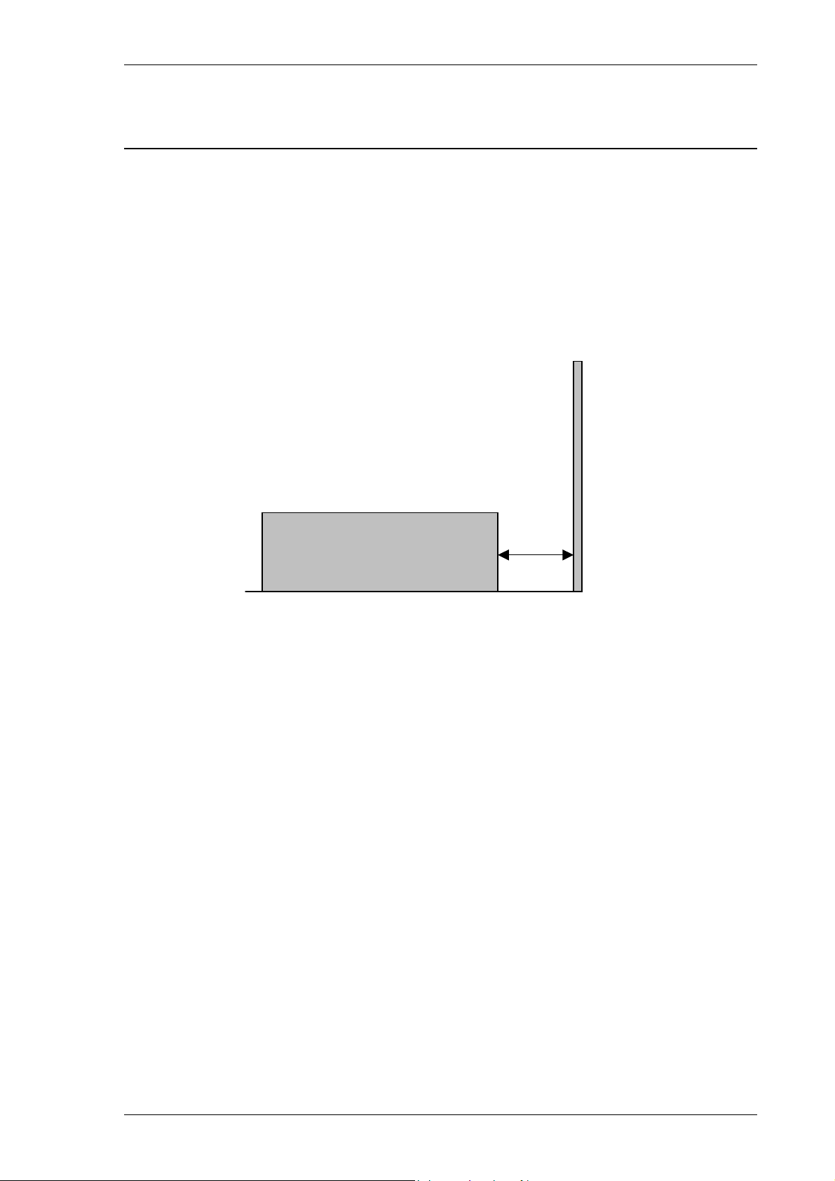
The calibrator can be used free standing on a bench or mounted in a standard 19”
rack enclosure. The calibrator can be operated at any angle; the two front feet have
tilt legs for bench operation. For all installations care must be taken not to cover the
ventilation slots underneath or block the fan. A 2” (5cm) space behind the instrument
is also required for line and interface connections.
Minimum 2” (5cm) Clearance
TRANSMILLE LTD. Version 5.00: February 2011 Page 10
Page 11
3000A SERIES OPERATION MANUAL
Rear Panel Connections and Controls
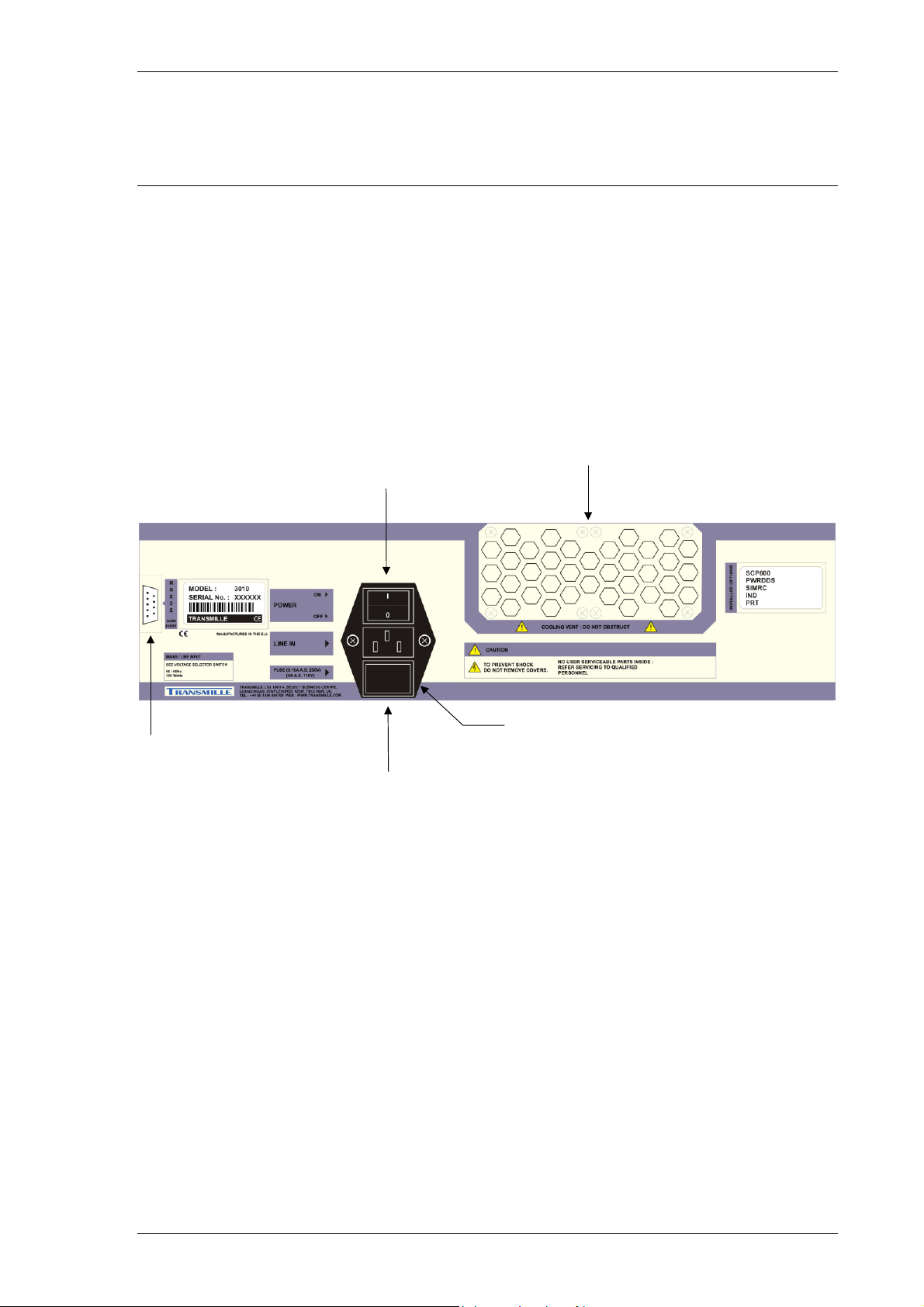
Connections on the rear panel are for Line Power via a 3 Pin IEC connector
incorporating the Line fuse and on-off switch; Note the mains inlet is filtered. A 9 Pin
Serial interface connector for the computer interface, this is optically isolated from
the calibrators output. On some models a third connector for the 10kV Extension
amplifier is also present.
Power
Switch
Cooling Fan Vent
(Keep Clear)
RS232 Connector
(COM Port)
Fuse Holder / Line Voltage Selector
Mains / Line Inlet
(IEC) Connector
TRANSMILLE LTD. Version 5.00: February 2011 Page 11
Page 12
3000A SERIES OPERATION MANUAL
Setting and checking the Line Voltage.
Warning: The line power cord must have an earth
conductor to avoid risk of shock.
This instrument must be correctly earthed.
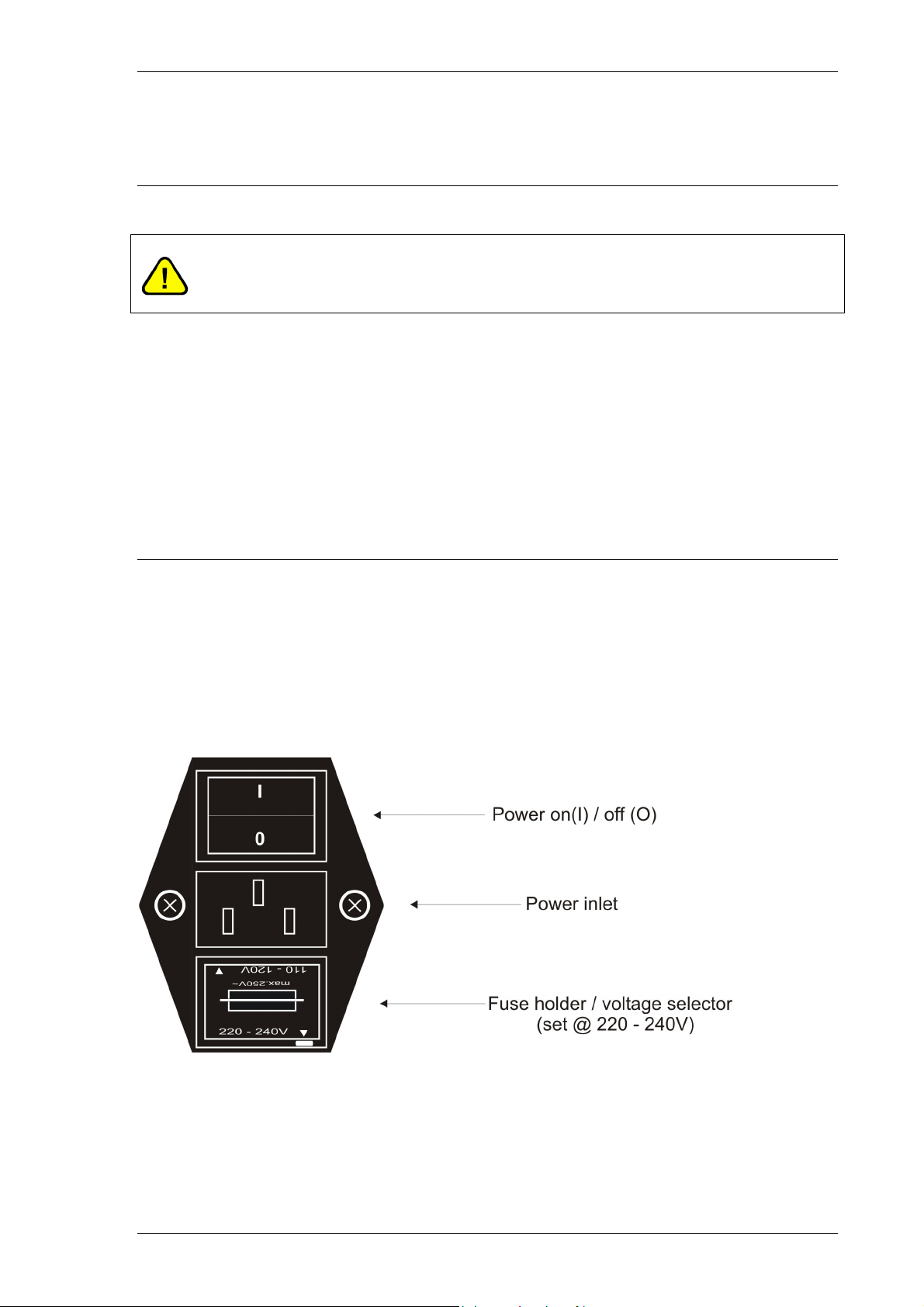
The calibrator has been designed to work from either 100-120 Volt line supply or
200 - 240 Volt line supply. Check that the voltage selector is set at the correct
voltage before connecting the power to the instrument. Connecting the calibrator to
the wrong supply will cause internal damage to the instrument. To change the line
voltage, remove the fuse / voltage selector housing, rotate through 180° and replace
with the required voltage setting at the bottom of the housing indicated by the arrow,
ensure that the correct fuse is fitted. The calibrator is set for 110V operation in the
USA, 230V operation in the UK and Europe.
Power Line Inlet Fuse and rating
The power line inlet fuse is located directly below the power inlet within the voltage
selector housing. The correct fuse rating is 3.15A anti-surge for 230V operation and
5A anti-surge for 110V operation.
TRANSMILLE LTD. Version 5.00: February 2011 Page 12
Page 13
3000A SERIES OPERATION MANUAL
Connecting to a computer
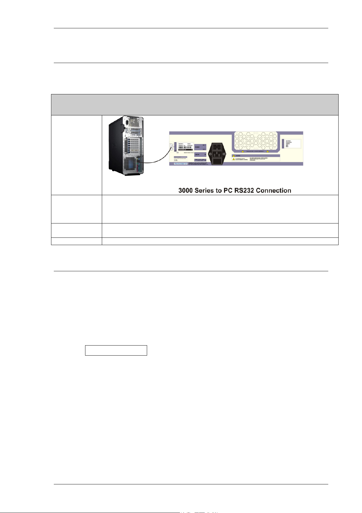
A standard serial 9 pin cable (supplied) should be used to connect the calibrator to a
COM port on the PC. A Null modem cable is not needed.
RS232 Interface
Connection
Configuration
Cable Type Male to Female Serial Cable
Driver N/A
BAUD RATE : 9600
PARITY : NONE
DATA BITS : 8
STOP BITS : 1
Straight Though Pin Connection (Not Null MODEM)
Powering up the calibrator
After connecting line power, the calibrator can be switched on with the line power
switch above the mains inlet socket on the rear panel.
The fan will start and the front panel display will illuminate indicating power. The
display will show a firmware version number and after a short delay, during which
time the processor performs a self-test of the instrument, the display will show an
output of 0.00000mV DC. Allow the calibrator to warm up for 30 minutes to
obtain full accuracy; the fast start feature of the calibrator will give approx. 90% of
full specifications within 10 minutes. The calibrator has been designed to be
powered up continuously, automatically switching to a standby mode after a pre-set
period of time from the last command. In standby mode the display back light will
turn off.
The control program can now be started on the computer, the program will establish
communication with the calibrator at which time the calibrator will download the
values of the internal standards.
TRANSMILLE LTD. Version 5.00: February 2011 Page 13
Page 14
3000A SERIES OPERATION MANUAL
Output Connections
Warning: Risk of shock.
High voltages may be present on the output sockets.
Output sockets are all 4mm safety type, the voltage pair contacts are low thermal
gold plated for minimum thermal EMF.
The 3000A series calibrator’s outputs have been designed to allow most multimeters
to be calibrated without changing connections. There are 3 separate pairs of
outputs:
1) Voltage, Resistance, Capacitance, Frequency & Inductance
2) Current and 4 Wire Resistance
3) High 30A Current.
When an output terminal pair is not active they are completely open circuit and
isolated from the other outputs. As only one pair is active at a time on (except on 4
wire ohms) they may be combined together if required to match the meters input
arrangement.
One example is the configuration of multimeters inputs with a single common low
and inputs with voltage, low and high current. To match this to the calibrator, simply
connect the 3 low outputs of the calibrator together and connect the voltage, low &
high current outputs to the appropriate meters inputs. Note that when outputting
resistance, the calibrator will use the voltage output terminals.
TRANSMILLE LTD. Version 5.00: February 2011 Page 14
Page 15
3000A SERIES OPERATION MANUAL
A second example is where the meter has separate voltage and current inputs, often
using four wire ohms on both pairs. In this case simply connect the voltage and
current outputs to the meter’s inputs, the calibrator will use both the voltage and
current pair on 4 wire ohms.
It is recommended that the voltage and low current leads be high quality screened
cable with gold plated 4mm plugs fitted. The cable must be able to withstand 1025
volts AC and have an insulation resistance greater than 1TΩ to avoid introducing
any shunting effect on the high resistance ranges.
Poor quality test leads will introduce noise, thermal e.m.f. and leakage errors on low
voltage & current ranges and also unstable readings on resistance and capacitance
outputs (see measurement techniques). Special test leads are available from
Transmille, see accessories.
Warning: Under no circumstances should any voltage
be connected to the calibrator outputs
The low output can be connected to line earth or allowed to float as selected - see
operation section of this manual. It is recommended that the low is earthed which
will help to reduce noise on high ohms and low current. If allowed to float with
respect to line earth the low must remain within 50 volts of line earth. Outputs are
optically isolated from the RS232 interface
Output Overloads
If the calibrator is unable to drive the load then the output will be turned off and the
calibrator returned to standby mode. The message Standby will be displayed on
the front panel. The output will be automatically reset on setting the output again.
TRANSMILLE LTD. Version 5.00: February 2011 Page 15
Page 16
3000A SERIES OPERATION MANUAL
Operation
Safety Warnings
WARNING: The information in this section is intended only
for qualified personnel. The user must at all times be
adequately protected from electric shock. Qualified
personnel must ensure that operators of the equipment are
adequately insulated from connection points.
WARNING: This instrument is capable of generating both
DC and AC high voltages.
A soft carry-case and a hard transit case are available for
regular transportation of the calibrator.
Introduction to Operation
All functions of the 3000A Series Calibrator can be controlled from the front panel, or
controlled remotely by a computer over the interface. The front panel controls are
‘locked out’, but local control may be resumed by selecting a soft key - it must be
remembered that this action may disrupt the computer program.
TRANSMILLE LTD. Version 5.00: February 2011 Page 16
Page 17
3000A SERIES OPERATION MANUAL
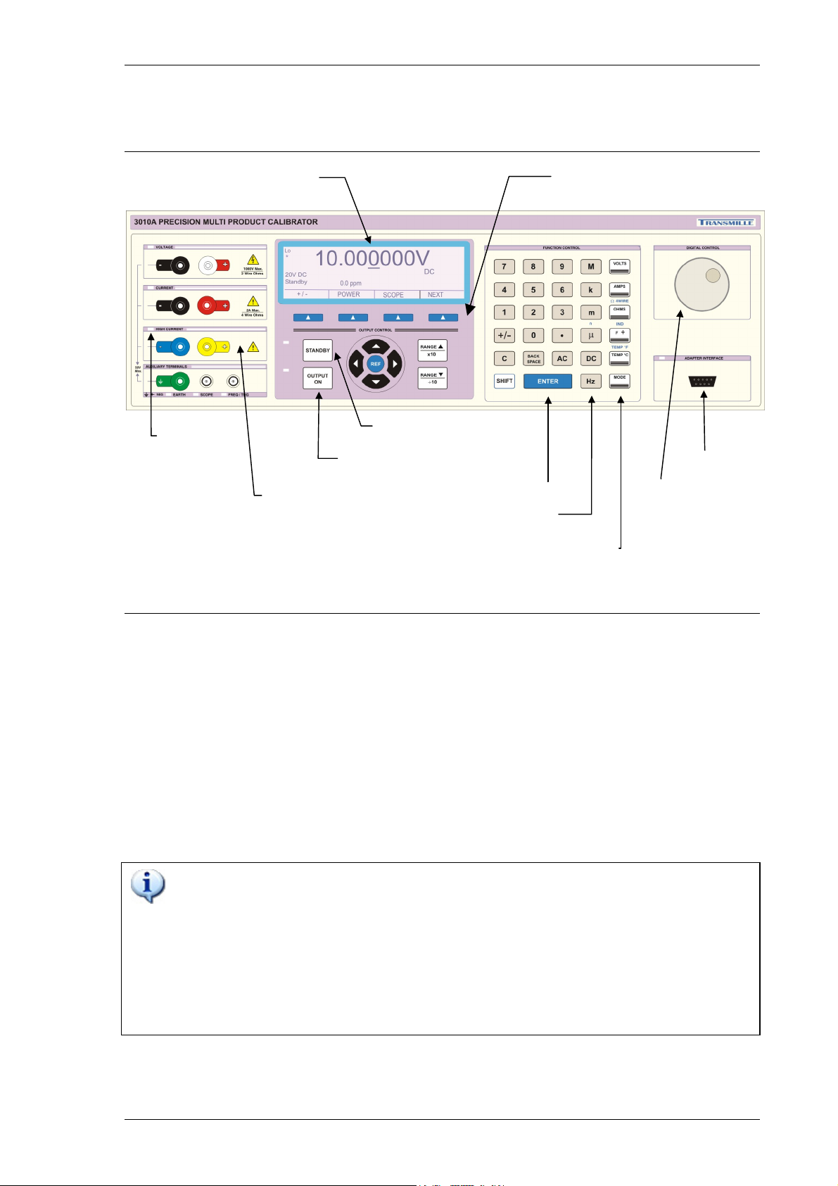
Front Panel Controls and Indicators
Active
Terminal
LEDs
LCD Display with
integral Backlight
Safety Output
Terminals
Standby Button
Output On Button
Numeric Keypad
Menu buttons
(Soft Keys)
Adapter Interface
Digital Control
Multiplier Keys
Function Keys
Front Panel Keyboard
The front panel of the 3000A Series Calibrator utilises a high quality custom rubber
keyboard with tactile feel buttons and integral display window. The front panel is
therefore sealed against the ingress of moisture and dirt enabling the calibrator to be
used in most working environments without risk of early failure of the operating
buttons. The front panel can easily be wiped clean with a soft cloth. Care should be
taken not scratch the display window. All graphics are ‘under printed’ making them
rugged and durable.
IMPORTANT NOTE
The front panel key buttons are for use with fingers only - do not press
the key with hard or sharp objects e.g. Ball-point pens, pencils,
screwdrivers etc. Repeated actions like this will almost certainly cause
the keyboard to fail. (This will not be covered under warranty). Care
should also be taken when transporting the instrument, do not place
test leads or other objects on top of the panel which may come into
contact with the display area and cause damage.
TRANSMILLE LTD. Version 5.00: February 2011 Page 17
Page 18
3000A SERIES OPERATION MANUAL
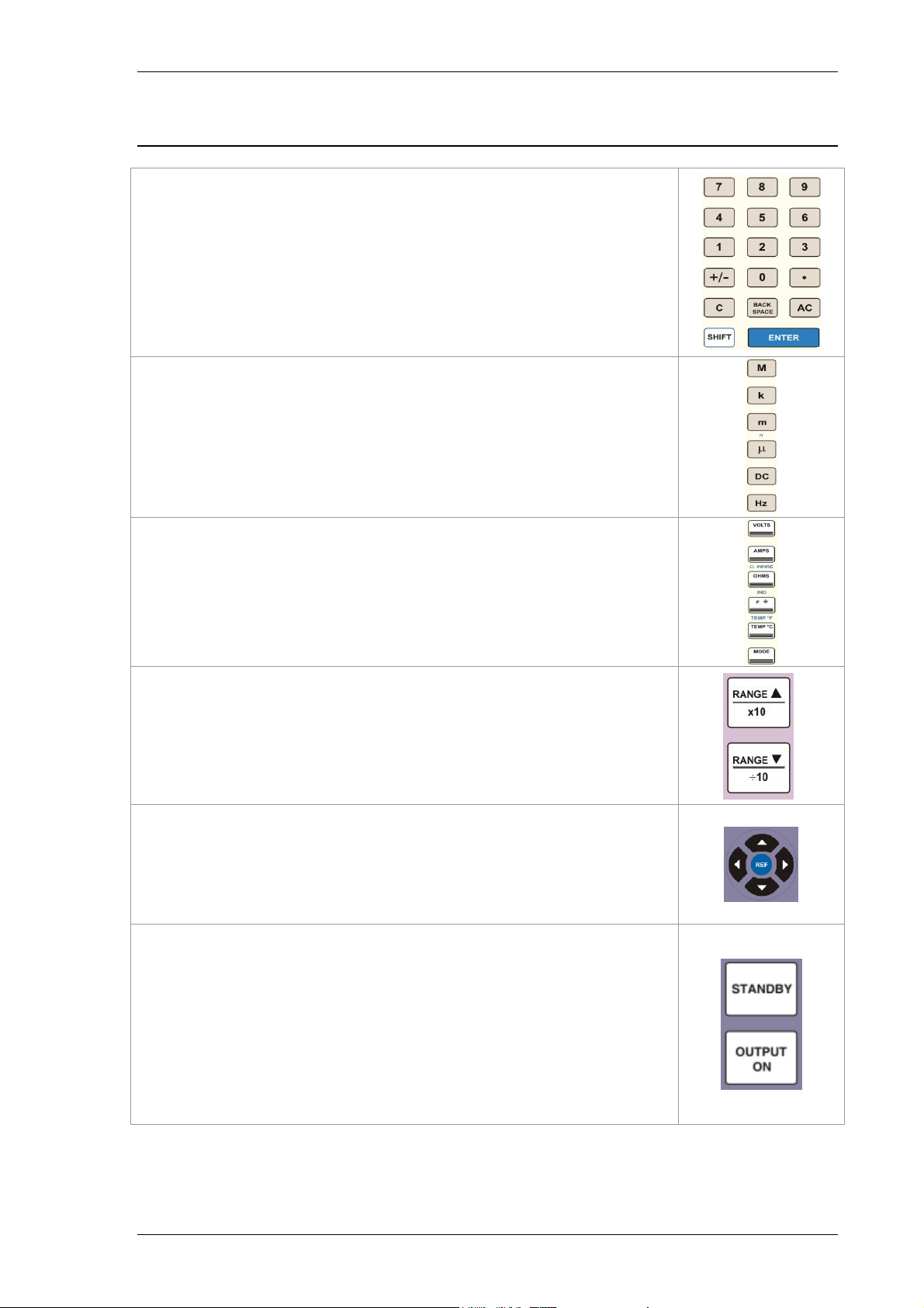
Front Panel Keyboard – Control Sections
The Keyboard is divided into sections to allow easy operation.
Numeric section
Allows numeric values to be entered
Multiplier section
Mega (M), kilo (k), milli (m), micro(u) or nano (n)
Function section
Volts (V), Amps(A), Ohms (2 & 4 Wire),
Farads(F), Celsius(C), & Frequency(Hz)
Range Up / Range Down
Allow the output to be multiplied / divided by 10.
Left / Right / Up / Down Arrow Keys
To select the digit to be controlled by the rotary control.
Output On / Standby keys
Allow the calibrators output to be disconnected from the
terminals. LED indicators are incorporated in these switches to
clearly show the output status.
TRANSMILLE LTD. Version 5.00: February 2011 Page 18
Page 19
3000A SERIES OPERATION MANUAL
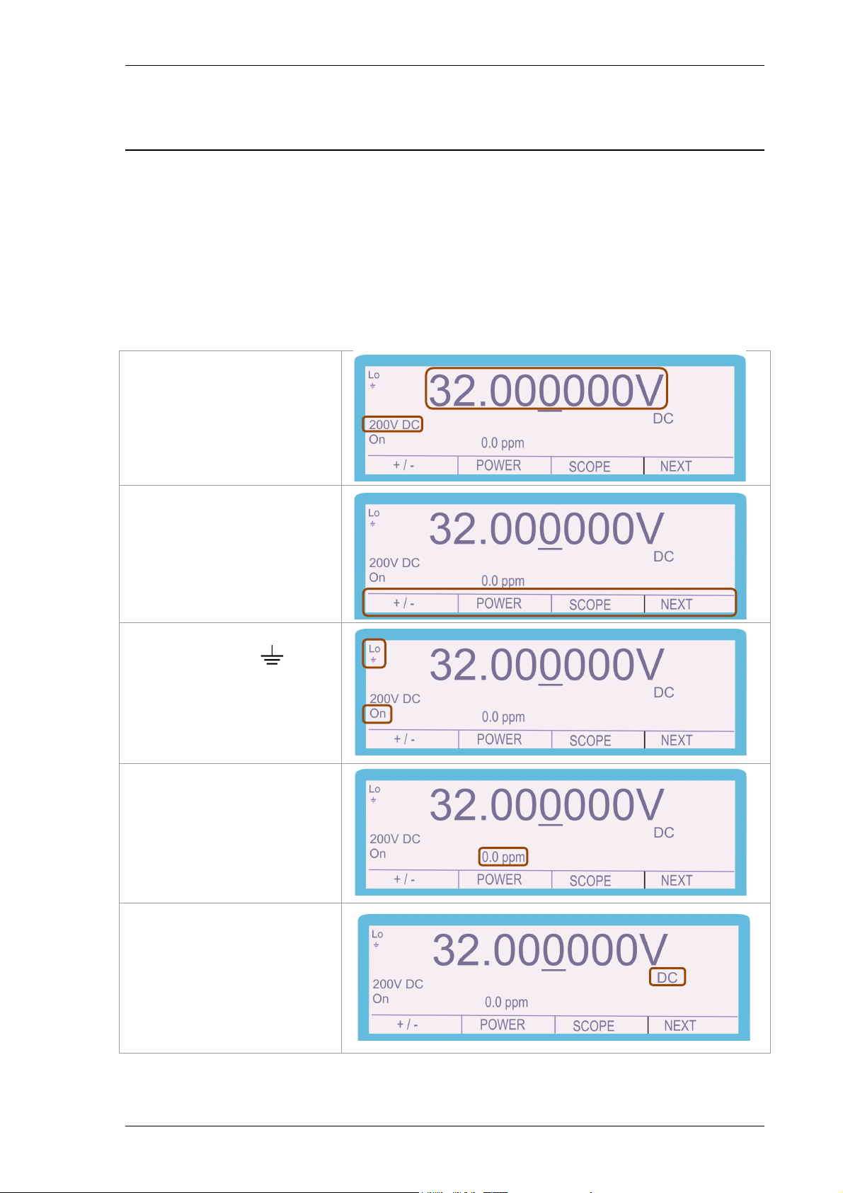
Graphic LCD Display
The graphic backlit LCD display shows the present output, instrument status, % or
ppm change from the entered value, and also the new value being entered. The
bottom portion of the display is used to assign the function of the four ‘soft (menu)
keys’. The display utilises a back light which automatically turns off if no activity
occurs either from the front panel keys or via a remote command.
Output Value &
Range
Dynamic
Soft key Menu
Lo to
Output On / Standby
Indicators
Deviation (ppm)
Function Specific
Configuration
Display
TRANSMILLE LTD. Version 5.00: February 2011 Page 19
Page 20
3000A SERIES OPERATION MANUAL
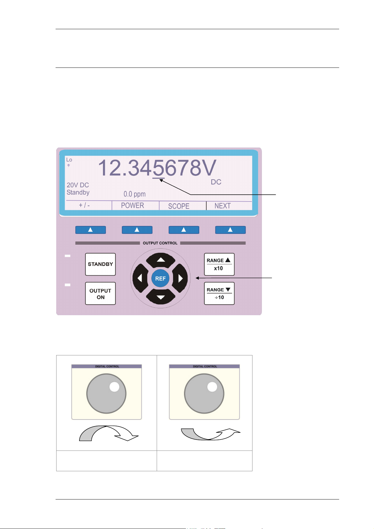
Digital Control
A digital potentiometer allows the ‘highlighted digit’ on the display to be incremented
(turning clockwise) or decrement (turning anti-clockwise). As an output is changed
the deviation from the original value entered on the keyboard is shown in either % or
ppm.
Selected digit marker.
Cursor Keys can be used to
move the position of the
digit marker, and increment /
decrement the digit.
Clockwise Rotation
(Increment Digit)
Anti-Clockwise Rotation
(Decrement Digit)
TRANSMILLE LTD. Version 5.00: February 2011 Page 20
Page 21
3000A SERIES OPERATION MANUAL
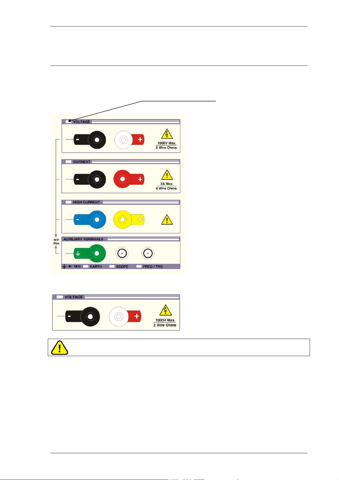
Terminal status LED’s
LED’s above the terminals indicate which pair is active. When terminals are not
active they are electrically isolated from each other, this enables terminals to be
linked together if required.
Active terminals
indicated by
illuminated LED
Voltage Output Terminal Pair (Black & White)
WARNING:
Dangerous voltage may be present on these terminals.
Low thermal 4mm safety terminals
Used for all voltage outputs up to 1025V, for 2 wire/4 wire resistance, capacitance
and inductance (optional). Note the low ‘black’ terminal can be internally switched to
line earth by a soft key function. When floating, the maximum voltage on this
terminal with respect to ground should not exceed 50 Volts peak.
TRANSMILLE LTD. Version 5.00: February 2011 Page 21
Page 22
3000A SERIES OPERATION MANUAL
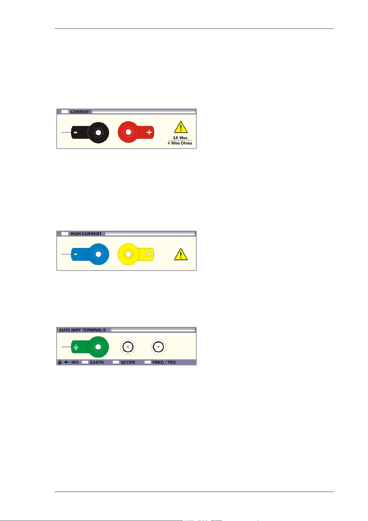
Current Output Terminals (Black & Red)
4mm safety terminals for all current outputs up to 2 Amps, TTL frequency and for
sense connection for 4 wire resistance.
Note the low ‘black’ terminal can be internally switched to line earth by a soft key
function. When floating, the maximum voltage on this terminal with respect to
ground should not exceed 50 Volts peak
30 Amps Output Terminals (Blue and Yellow)
4mm Safety terminals used for all currents above 2 Amps.
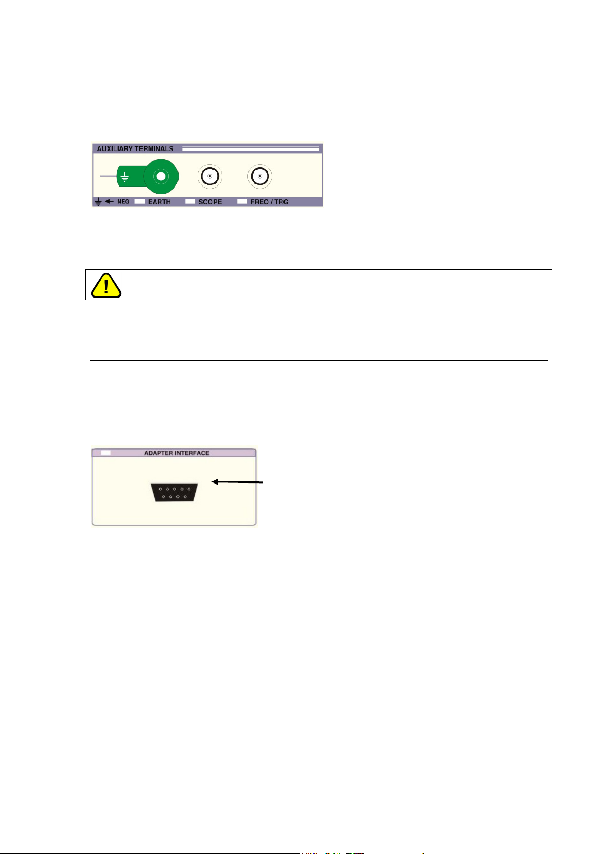
Earth Terminal (Green)
Connected directly to line earth and case. Incorporates green LED indication of
negative to earth (grounded or floating) selection
TRANSMILLE LTD. Version 5.00: February 2011 Page 22
Page 23
3000A SERIES OPERATION MANUAL
Scope & Freq/Trg BNC Connector Outputs
Isolated BNC sockets for frequency and oscilloscope function outputs. They
incorporate a green LED indicator to show when the terminal is active.
WARNING:
Dangerous voltages up to 400V may be present on these terminals.
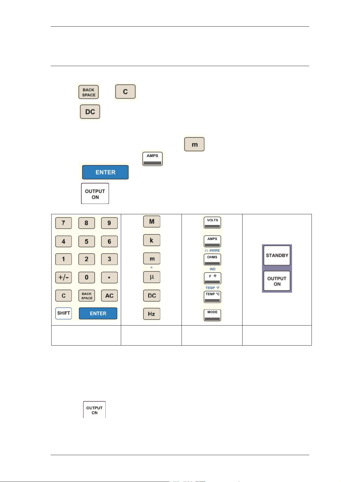
9 Pin Adapter Interface Connector.
Used for connection to external pods used for extending calibration capability, e.g.
Thermocouple simulation etc.
Adapter Interface 9 Way ‘D’ type
connector (Female)
Incorporates a green LED to indicate when the adapter interface is active.
The pins connections are as follows:
Pin 1 – +15V
Pin 2 – Digital ground
Pin 3 – Strobe
Pin 4 – Data
Pin 5 – Select
Pin 6 – -15V
Pin 7 – Analogue ground
Pin 8 – Output
Pin 9 – Input
TRANSMILLE LTD. Version 5.00: February 2011 Page 23
Page 24
3000A SERIES OPERATION MANUAL
Setting DC Voltage and Current Output
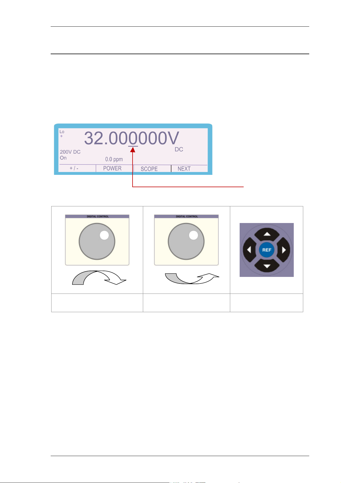
Complete the following procedure to set a dc voltage or current output.
Use the and (clear) keys to edit the entry.
1) Press
2) Press the numeric and decimal point keys to enter the required value, e.g. 12.345
3) Press the multiplier key (if required), e.g.
4) Press the function key e.g.
5) Press
6) Press to activate the calibrator output.
Key Digits
12.345
Press ‘m’
Multiplier
Press
Function Key
Select
Output On
The calibrator will now produce 12.345 mA D.C. at the appropriate terminals.
Once on a range, any new output within that range can be set without the calibrator
returning to standby. When a high voltage or high current values are entered the
calibrator will automatically go into standby mode. To output the voltage or current,
press the key. This safety feature stops the accidental selection of high
voltage or current.
TRANSMILLE LTD. Version 5.00: February 2011 Page 24
Page 25
3000A SERIES OPERATION MANUAL
Adjusting the set output using the digital control
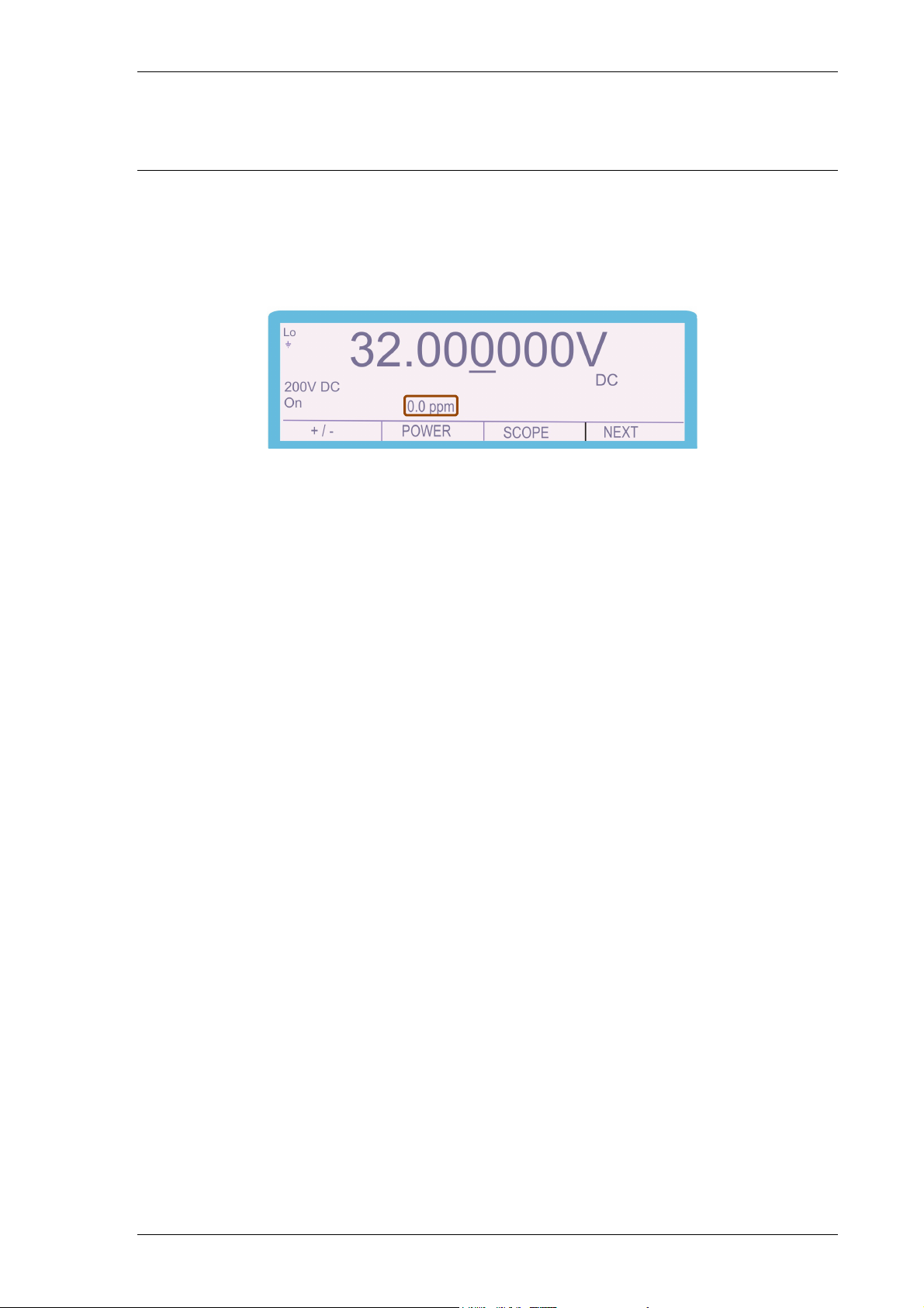
After the output has been set, any digit of the output display can be incremented or
decremented using either the digital control or the up and down arrow keys. The
digit selected is indicated by the cursor and can be changed by using the left and
right arrow keys.
Highlighted digit
Clockwise Rotation
(Increment Digit)
Anti-Clockwise Rotation
(Decrement Digit)
Up / Down
Cursor Buttons
TRANSMILLE LTD. Version 5.00: February 2011 Page 25
Page 26
3000A SERIES OPERATION MANUAL
Automatic Display of % or ppm Error and Ref. Key
When the output value is changed by the methods above, the display will show the
change in ppm or % from the original reference value entered from the keyboard. If
needed, the reference value can be reset to the present value on the display by the
REF key.
This feature is ideal for displaying the error in a meter under test by adjusting the
output from the calibrator to make the meter read the nominal value.
TRANSMILLE LTD. Version 5.00: February 2011 Page 26
Page 27
3000A SERIES OPERATION MANUAL
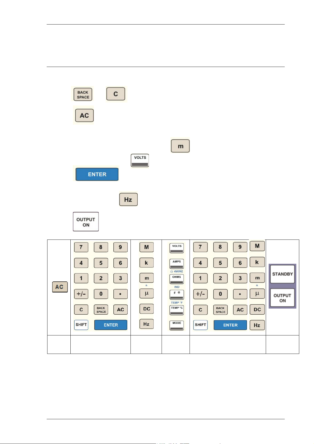
Setting AC Voltage and Current Output.
Complete the following procedure to set an ac voltage or current output.
Use the and (clear) keys to edit the entry.
1) Press
2) Press the numeric and decimal point keys to enter the required value, e.g. 16.789
3) Press the multiplier key (if required), e.g.
4) Press the function key e.g.
5) Press
6) Press the numeric and decimal point keys to enter the frequency value, e.g. 1000
7) Press the function key
8) Press to activate the calibrator output.
Select
AC
Key in Voltage /
Current Value
Select
Multiplier
Select
Function
Set Frequency Followed by
Hz Key
Select
Output On
The display will show the frequency in the bottom right hand corner of the display.
For safety, AC/DC changes will maintain the set output value; the output will switch
off and then back on again. The frequency can be adjusted using the digital control.
TRANSMILLE LTD. Version 5.00: February 2011 Page 27
Page 28
3000A SERIES OPERATION MANUAL
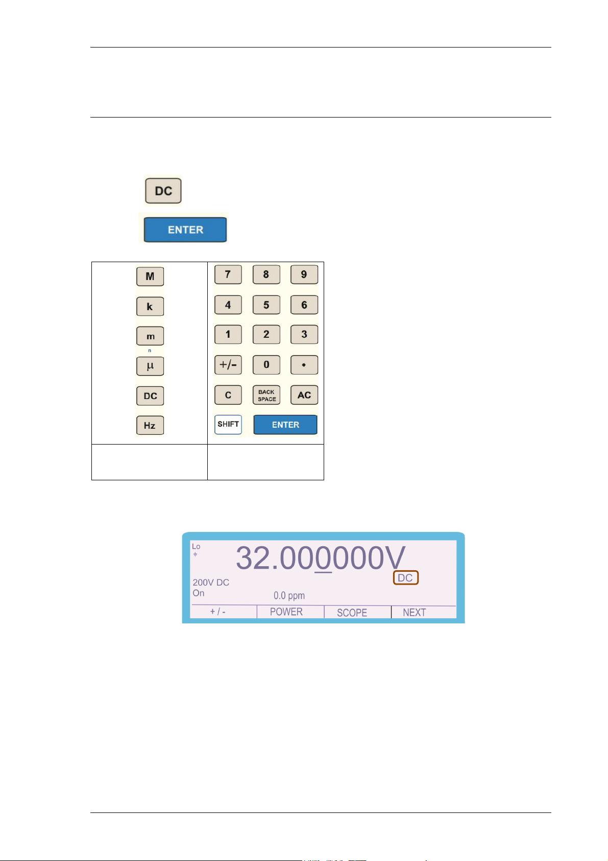
Returning the calibrator to DC
Complete the following procedure to return the output to DC:
1: Press
2: Press
Select DC
Key
Press
Enter
The display will indicate DC as shown above. The voltage or current setting will
remain as the previous setting.
TRANSMILLE LTD. Version 5.00: February 2011 Page 28
Page 29
3000A SERIES OPERATION MANUAL
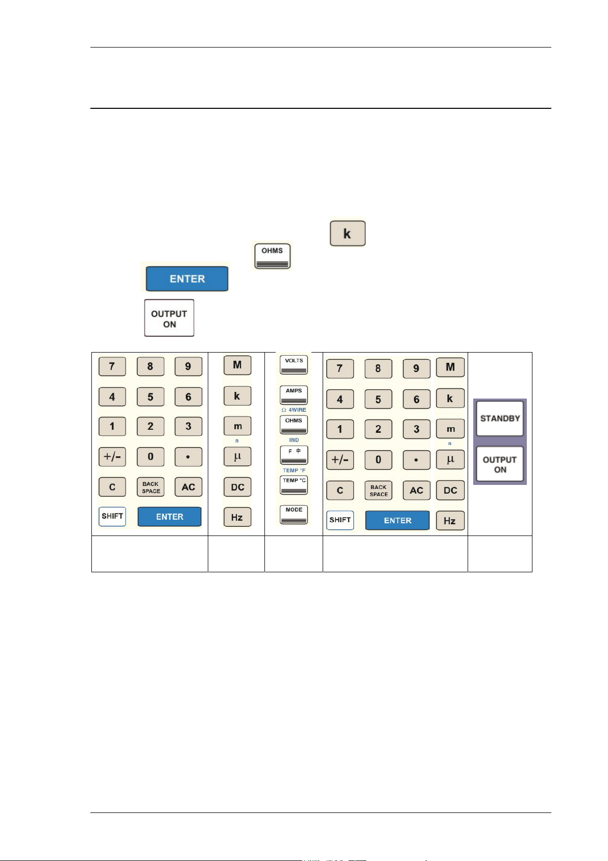
Setting 2 Wire Resistance Output.
Note: The calibrator uses standard resistors of fixed decade values. The nearest
available resistance to the entered value will be automatically selected. Complete
the following procedure to select 100kΩ in 2 wire mode.
1) Press the numeric keys to enter the required value, e.g. 100
2) Press the multiplier key (if required), e.g.
3) Press the function key e.g.
4) Press
5) Press
Key in
Resistance Value
Select
Multiplier
Select
Function
Press
Enter
Select
Output On
The resistance displayed will be the calibrated value held in the non-volatile
calibration memory for that standard. Note the values are different for two and four
wire ohms.
Nulling DMM
The calibrated values displayed for 2 wire ohms are the values present at the
terminals. Therefore the measuring instrument should be zeroed (Nulled) with the
leads shorted before connection to the calibrator.
TRANSMILLE LTD. Version 5.00: February 2011 Page 29
Page 30
3000A SERIES OPERATION MANUAL
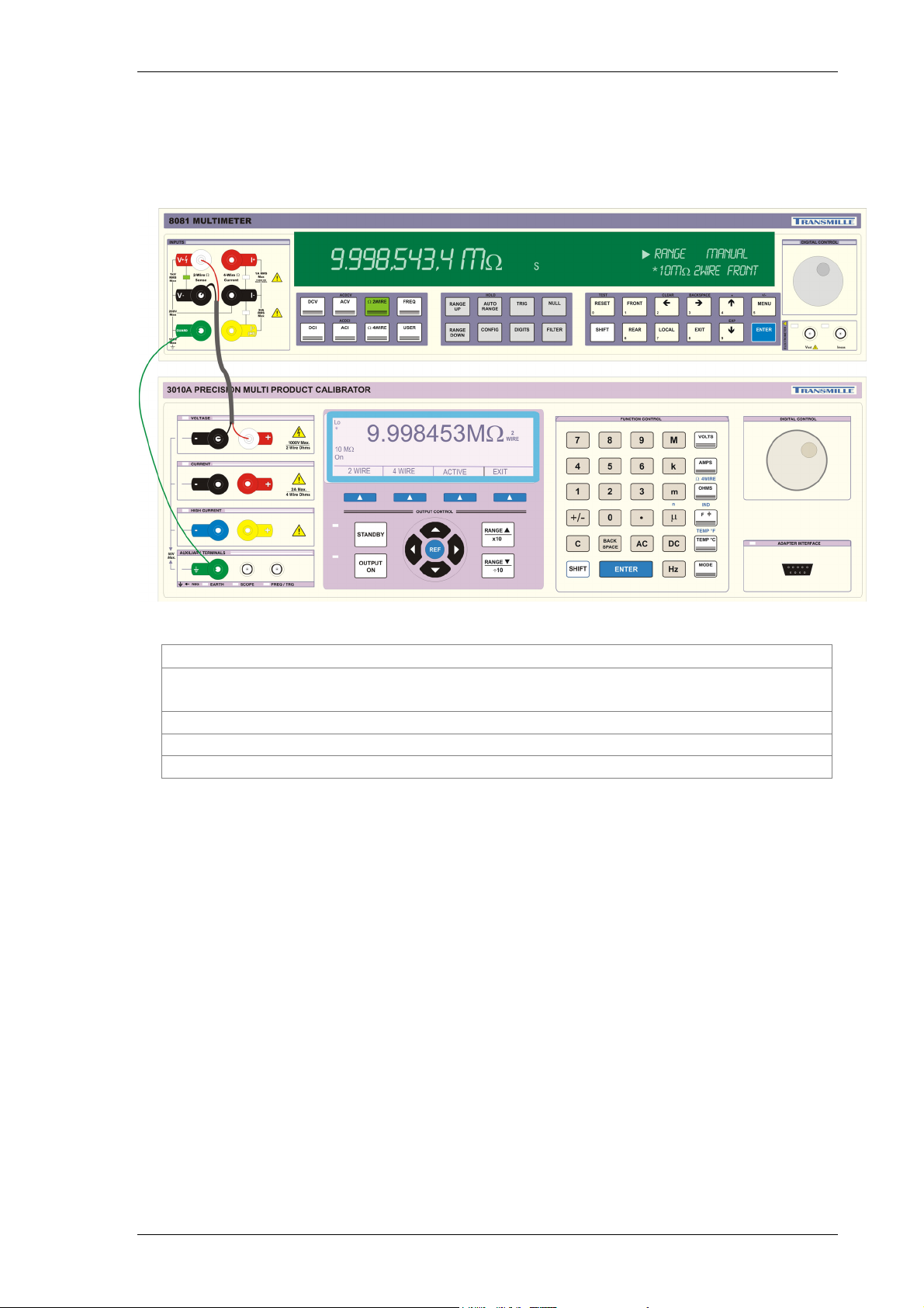
2 Wire Ohms Operation
Two wire ohms is output on the voltage terminals as indicated by the terminal LED’s.
2 Wire Ohms Connection
Connect the measuring instrument 2-Wire input to the calibrator
2-Wire resistance output.
Use shielded connection cables – 50 Ohm co-axial recommended
Connect Guard / Earth if required – see notes
Select 2 Wire resistance measurement mode on meter
TRANSMILLE LTD. Version 5.00: February 2011 Page 30
Page 31
3000A SERIES OPERATION MANUAL
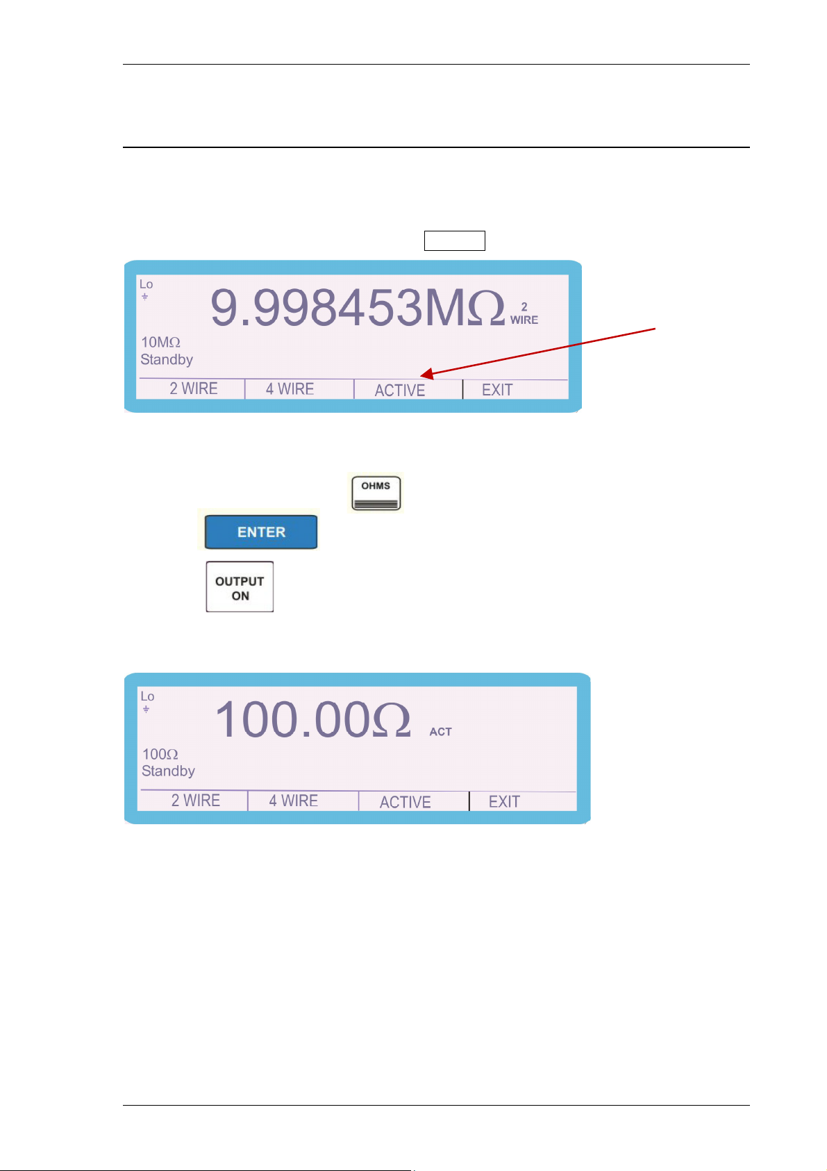
Setting 2 Wire Simulated Resistance (Option)
The calibrator can simulate (Active) 2 wire resistance vales in the range of 0Ω to
10MΩ
1) From the resistance screen press the ACTIVE soft key
Active Ω
2) Press the numeric keys to enter the required value, e.g. 100
3) Press the function key e.g.
4) Press
5) Press
Ω
TRANSMILLE LTD. Version 5.00: February 2011 Page 31
Page 32
3000A SERIES OPERATION MANUAL
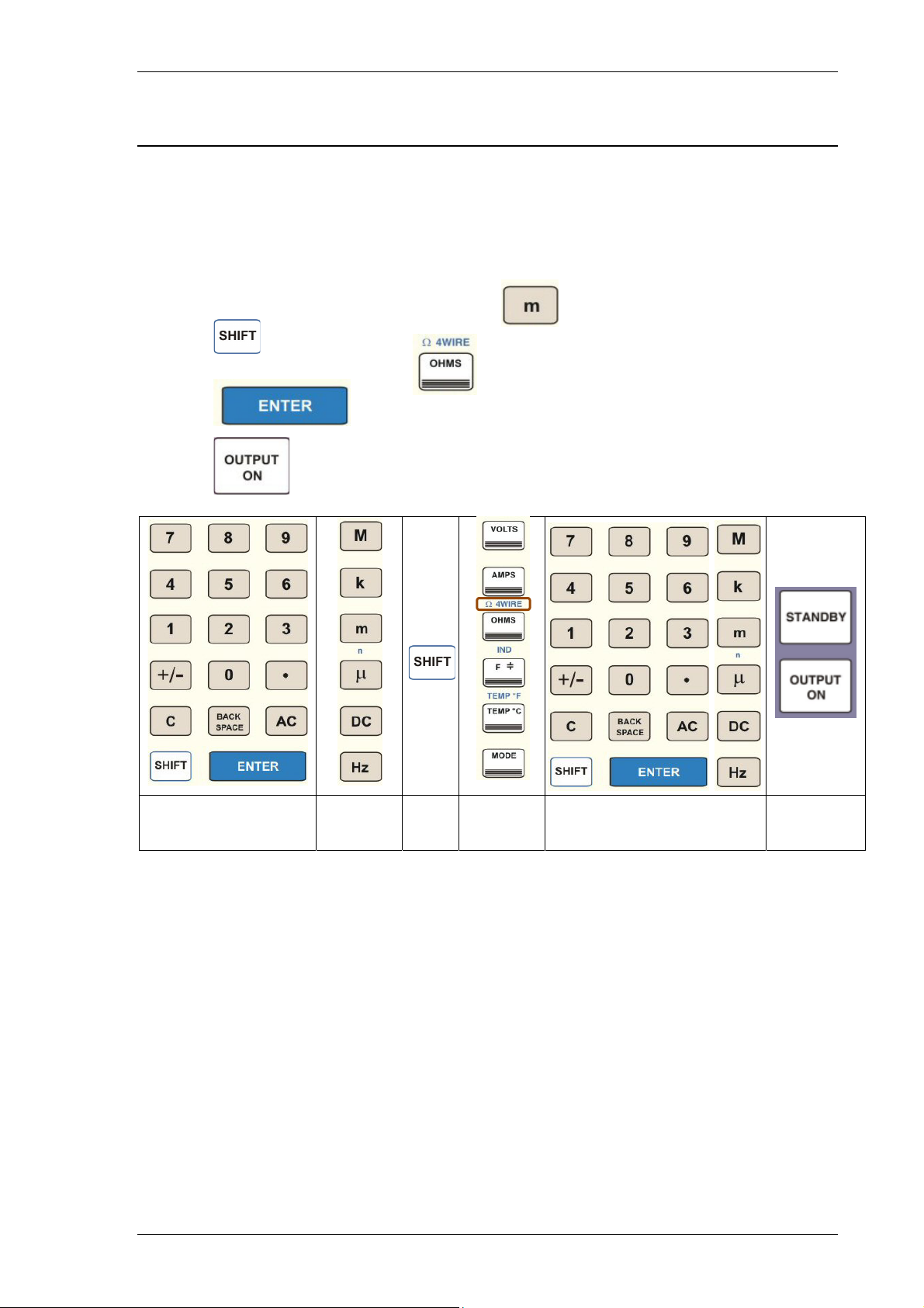
Setting 4 Wire Resistance Output.
Note: The calibrator uses standard resistors of fixed decade values. The nearest
available resistance to the entered value will be automatically selected. Complete
the following procedure to select 100mΩ in 4 wire mode.
1) Press the numeric keys to enter the required value, e.g. 100
2) Press the multiplier key (if required), e.g.
3) Press
4) Followed by the shift-function
5) Press
6) Press
Key in
Resistance Value
Select
Multiplier
Shift Select
Function
Press
Enter
Select
Output On
The resistance displayed will be the calibrated value held in the non-volatile
calibration memory for that standard. Note the values are different for two and four
wire ohms. Four wire ohms is indicated on the terminal LED’s by both the voltage
and current terminal LEDs illuminating.
Nulling DMM
The calibrated values displayed for 4 wire ohms are the values referenced to the
calibrator’s zero position. Therefore, the measuring instrument should be zeroed
(Nulled) with all 4 leads (top leads sense, lower leads current) connected to the
calibrator with the zero ohms selected.
TRANSMILLE LTD. Version 5.00: February 2011 Page 32
Page 33
3000A SERIES OPERATION MANUAL
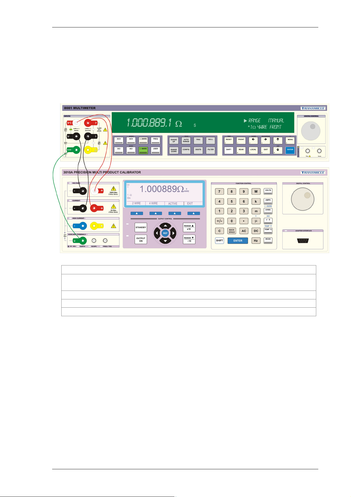
4 Wire Ohms Operation
Four wire ohms is output on the voltage and current terminals as indicated by the
terminal LED’s. Connect the ‘sense’ from the DMM to the voltage output on the
calibrator, and connect the ‘current’ from the DMM to the calibrator current
terminals.
4 Wire Ohms Connection
Connect the measuring instrument 4-Wire input to the calibrator
4-Wire resistance output.
Use low thermal leads and connections
Connect Guard / Earth if required – see notes
Select 4 Wire resistance measurement mode on meter
TRANSMILLE LTD. Version 5.00: February 2011 Page 33
Page 34
3000A SERIES OPERATION MANUAL
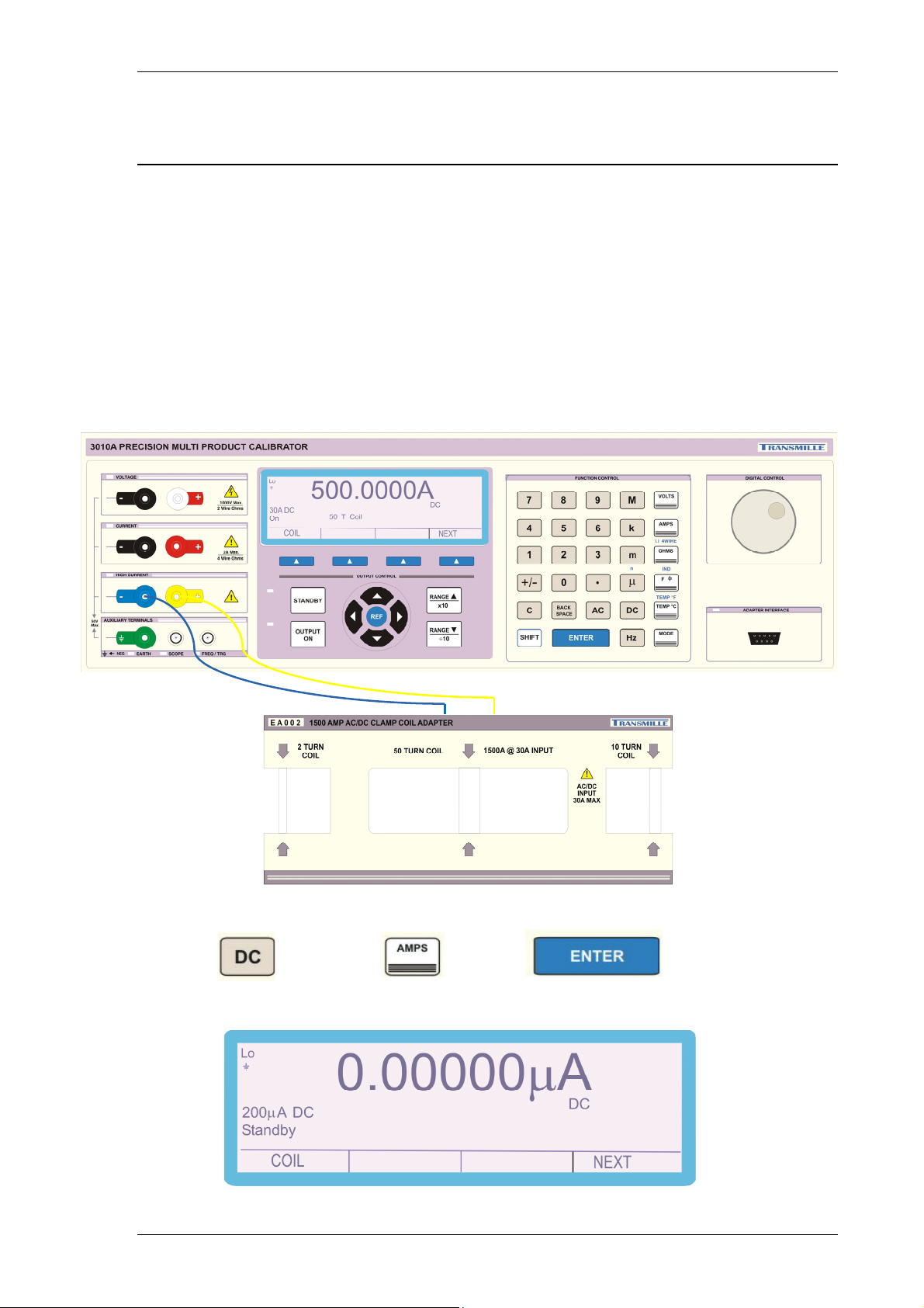
Using Current Coils (Option)
The 3000A Calibrators can be used with the optional current coil EA002 (2, 10 and
50 turn coil). This enables currents both DC and AC of up to 1500A with the 3041A
and 3010A Calibrators and 1000A with the 3050A Calibrator to be produced for the
calibration of current clamp meters.
The current from the calibrator is connected the appropriate coil connections. The
current output from the calibrator is then multiplied by the number of turns in that coil
producing a higher current for the clamp to measure.
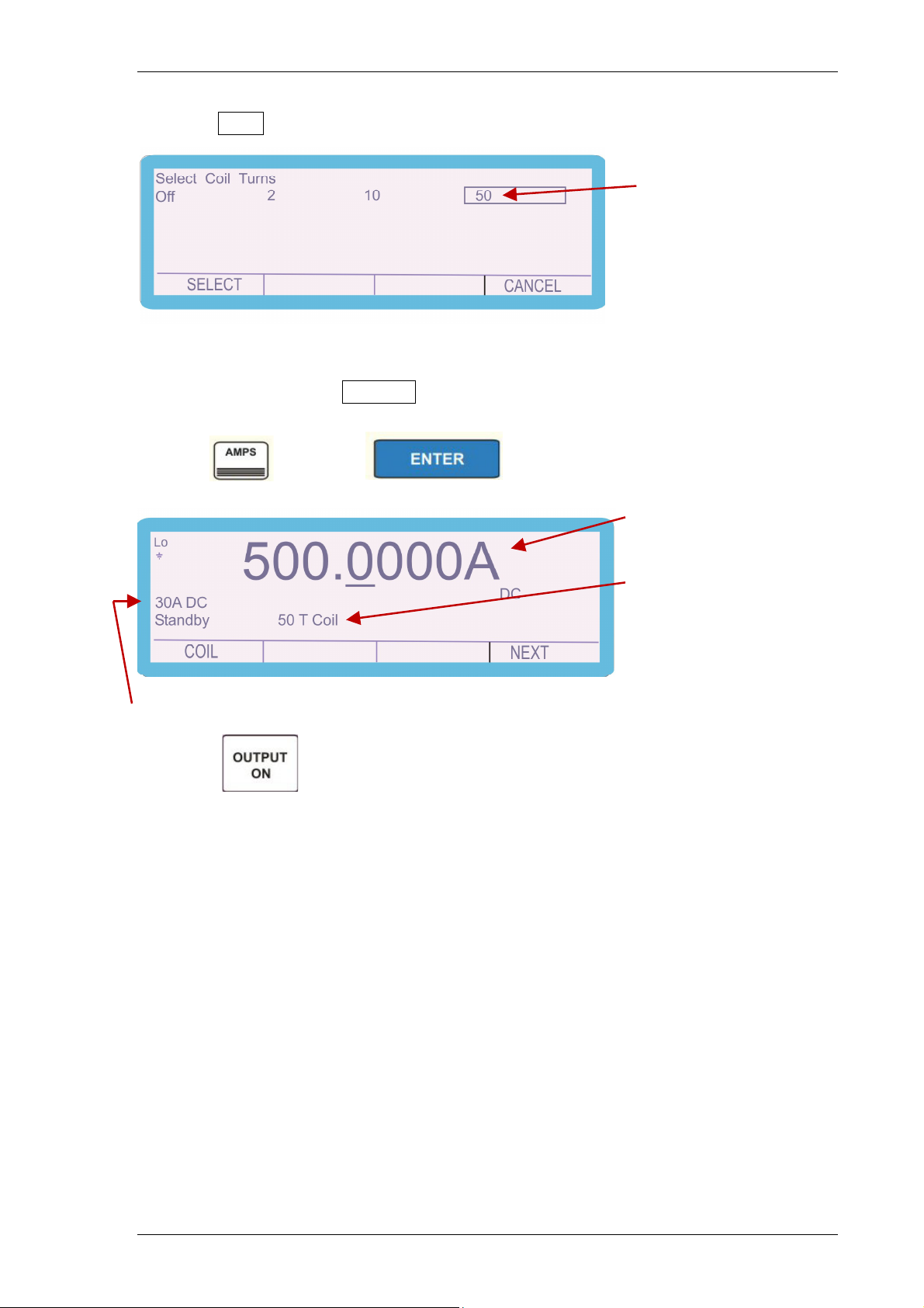
Complete the following procedure to select 500A DC using the 50 turn coil.
1) Press followed by and then to display the screen
below.
TRANSMILLE LTD. Version 5.00: February 2011 Page 34
Page 35
3000A SERIES OPERATION MANUAL
2) Select COIL using the soft key to enter the screen shown
Number of turns
Use the arrow keys, left and right to place the highlighted box over the coil type
required and then press SELECT
3) Press the numeric keys to enter the required value, e.g. 500
4) Press followed by to display screen below.
500A (50 turns x 10A)
50 turn coil selected
30A range output selected automatically as current output required >2A
5) Press
TRANSMILLE LTD. Version 5.00: February 2011 Page 35
Page 36
3000A SERIES OPERATION MANUAL
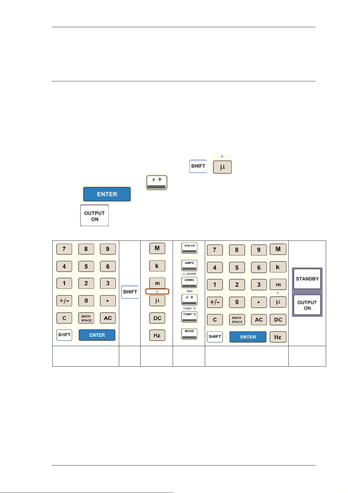
Setting Capacitance Output.
Note: The calibrator uses standard capacitors of fixed values. The nearest available
capacitance to the entered value will be automatically selected. Complete the
following procedure to select 100nF.
1) Press the numeric keys to enter the required value, e.g. 100
2) Press the multiplier key (if required), e.g.
3) Press the function key e.g.
4) Press
5) Press
Key in
Capacitance Value
Shift Select
Multiplier
Select
Function
Press
Enter
Select
Output On
Capacitance is available at the voltage terminals as indicated by the LED.
The capacitance displayed will be the calibrated value held in the non-volatile
calibration memory for that standard. Note this is the value measured with a 1 kHz
sine wave on a LCR bridge. When measuring capacitance, Cp (parallel) should be
selected for values up to and including 1uF and Cs (series) for values above.
TRANSMILLE LTD. Version 5.00: February 2011 Page 36
Page 37
3000A SERIES OPERATION MANUAL
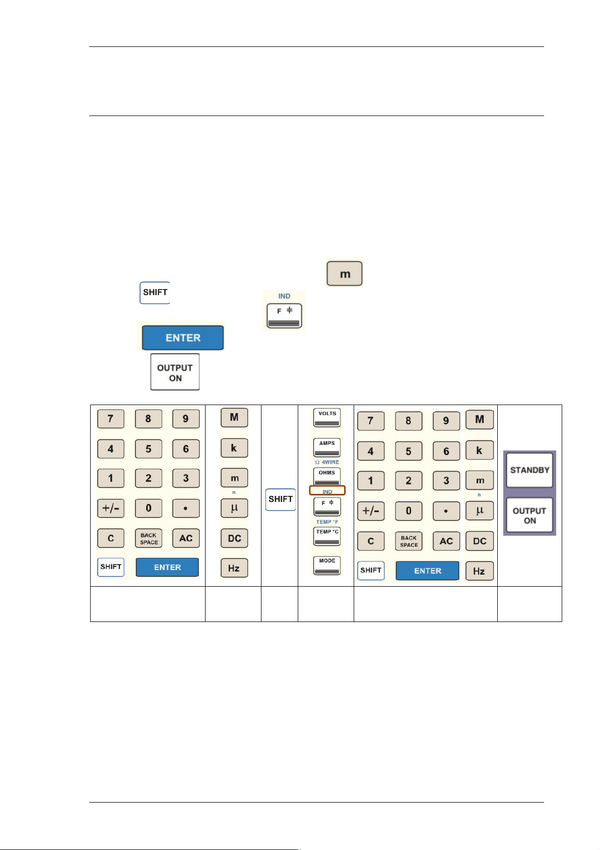
Setting Inductance Output (Option)
Note: The calibrator uses standard inductors of fixed values. The nearest available
inductance to the entered value will be automatically selected. Complete the
following procedure to select 10mH.
1) Press the numeric keys to enter the required value, e.g. 10
2) Press the multiplier key (if required), e.g.
3) Press
4) Followed by the shift-function
5) Press
6) Press
Key in
Inductance Value
Select
Multiplier
Shift Select
Function
Press
Enter
Select
Output On
Inductance is available at the voltage terminals as indicated by the LED. The
inductance displayed will be the calibrated value held in the non-volatile calibration
memory for that standard.
TRANSMILLE LTD. Version 5.00: February 2011 Page 37
Page 38
3000A SERIES OPERATION MANUAL
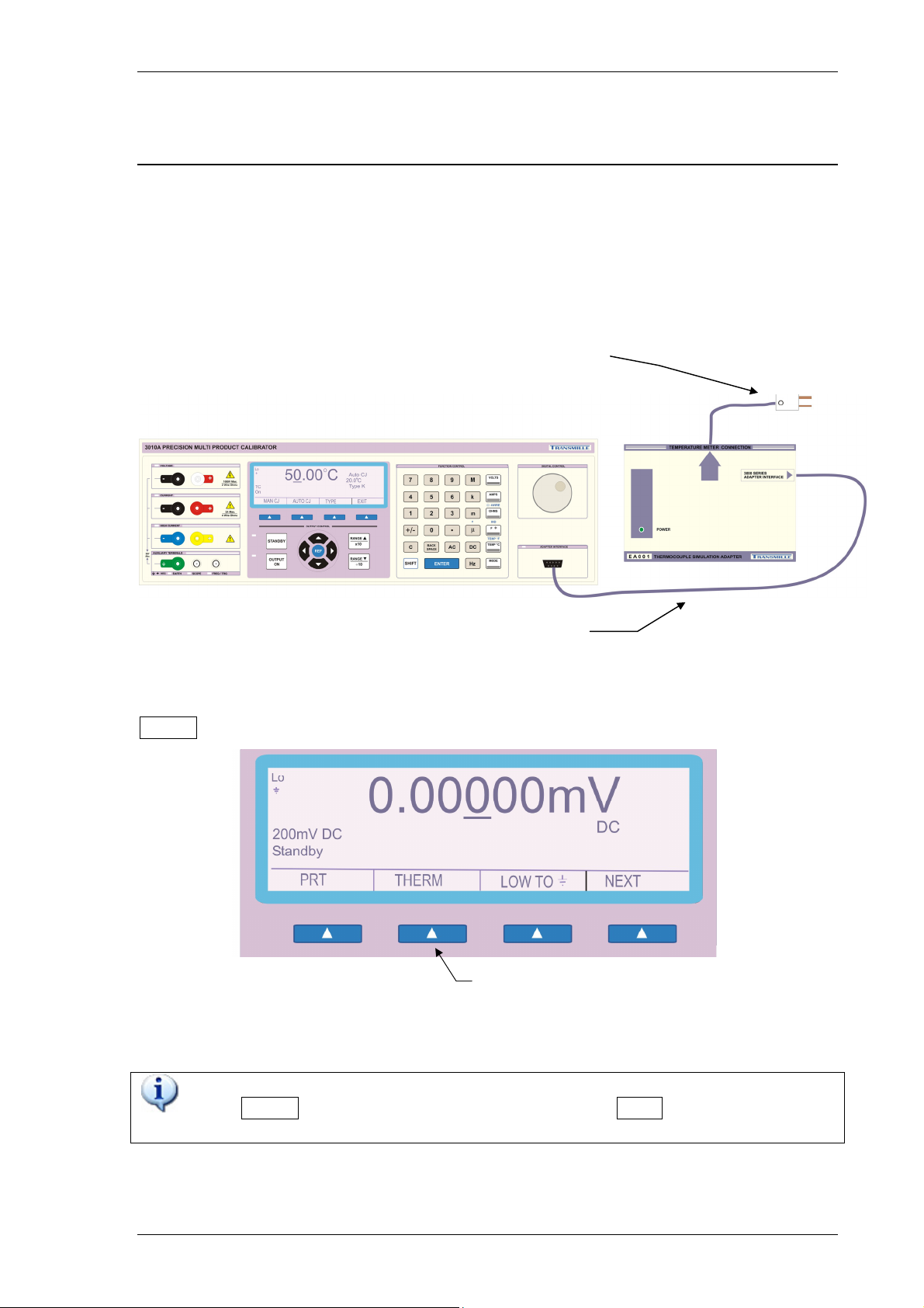
Thermocouple Simulation (Option).
Thermocouple Adapter Connection
Using the supplied adapter connection lead (9 way ‘D’ type to 9 way ‘D’ type),
connect the thermocouple adapter to the adapter interface connection on the front
panel of the 3000A series calibrator.
‘Neutral’ (Copper)
Thermocouple Plug Connects To UUT
9 way ‘D’ to 9 way
‘D’ connection
Starting the Thermocouple Simulation Option
To start the thermocouple simulation option, press the soft key below the
THERM menu item
Thermocouple Mode soft key
TIP
If the THERM menu item is not displayed, press the NEXT soft key
to go to the next menu level.
TRANSMILLE LTD. Version 5.00: February 2011 Page 38
Page 39
3000A SERIES OPERATION MANUAL
Thermocouple Simulation Option Operation
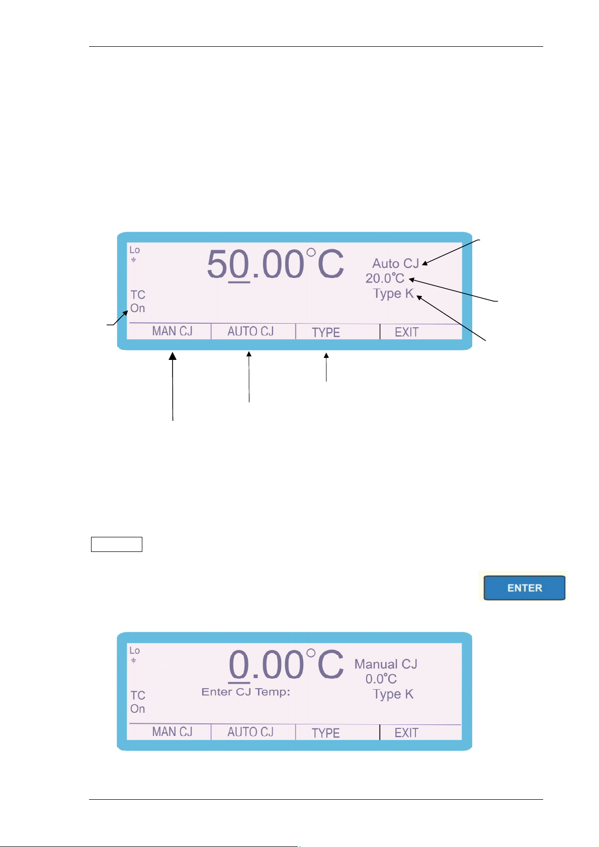
The thermocouple simulation option allows the user to enter a temperature in °C and
set the calibrator to the specific voltage output which corresponds to the
thermocouple type selected. On entering thermocouple simulation mode, type K will
be the default function. The display below will be shown indicating the currently
selected range and output status:
Output status
(On / Standby)
Once in thermocouple mode, the menus available at the bottom of the screen will
change to reflect the thermocouple mode options - the available functions are:
Cold junction
compensation type
AutoCJ = Automatic
ManualCJ = Manual
Cold junction
compensation
temperature
Thermocouple
Type
Change thermocouple type soft key
Auto Cold junction soft key
Manual Cold junction soft key
Selects the manual cold junction compensation mode.
MAN CJ
Press the key and ‘Enter CJ Temp:’ appears on the display as shown.
Input the required value via the numeric keypad and press
TRANSMILLE LTD. Version 5.00: February 2011 Page 39
Page 40
3000A SERIES OPERATION MANUAL
A
UTO CJ
Selects the automatic cold junction compensation mode
This allows the calibrator to use the built in temperature sensor within
the adapter’s thermocouple plug to compensate for the cold junction
measured between the adapter plug and the UUT socket.
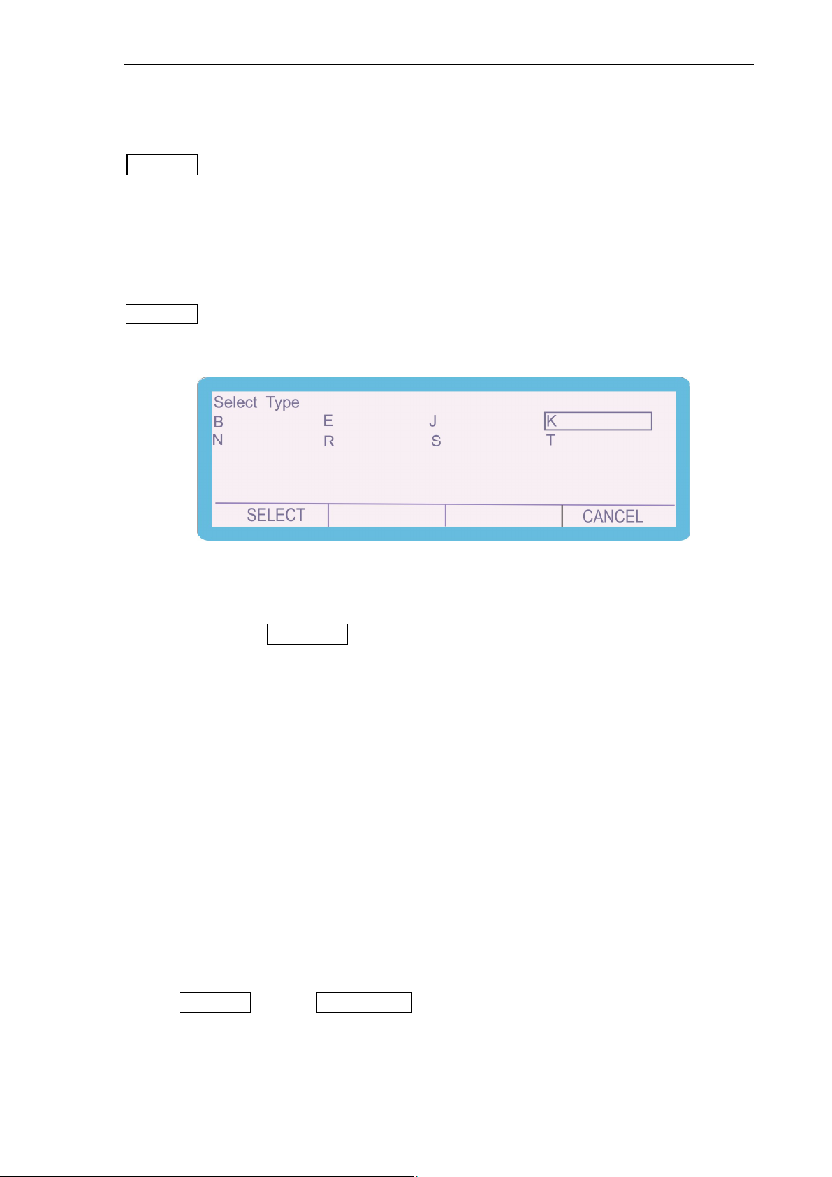
TYPE Selects the thermocouple currently being simulated.
Press the key and the screen changes to the display below.
Use the arrow keys, up and down, left and right to place the
highlighted box over the thermocouple type required and then
press SELECT
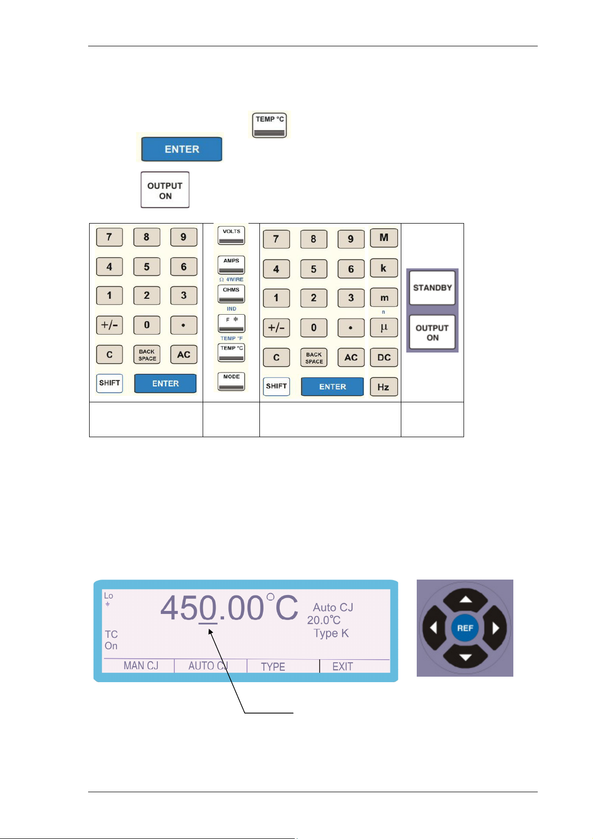
Complete the following procedure to select K type simulation equivalent to 450°C
1) Connect the thermocouple simulation adapter to the 3000A Series calibrator via
its feature connector using the supplied 9 way ‘D’ type to 9 way ‘D’ type lead.
Connect the UUT to the thermocouple plug extending from the opposite end of the
thermocouple simulation adapter. Set the UUT to the required range.
2) Select the thermocouple type to be simulated as described above in this case K
type.
3) Select the cold junction compensation options using the soft keys, either
or
MAN CJ AUTO CJ
TRANSMILLE LTD. Version 5.00: February 2011 Page 40
Page 41
3000A SERIES OPERATION MANUAL
4) Press the numeric keys to enter the required value, e.g. 450
5) Press the function key e.g.
6) Press
7) Press
Select
Output On
Key in
Temperature Value
Select
Function
Press
Enter
8) To change the temperature output from the nominal value, use the deviation
function. This is controlled by using the left and right arrow keys to select the digit
to be incremented.
Use the left right arrows to highlight the digit to
be adjusted (indicated by the underlined digit)
TRANSMILLE LTD. Version 5.00: February 2011 Page 41
Page 42
3000A SERIES OPERATION MANUAL
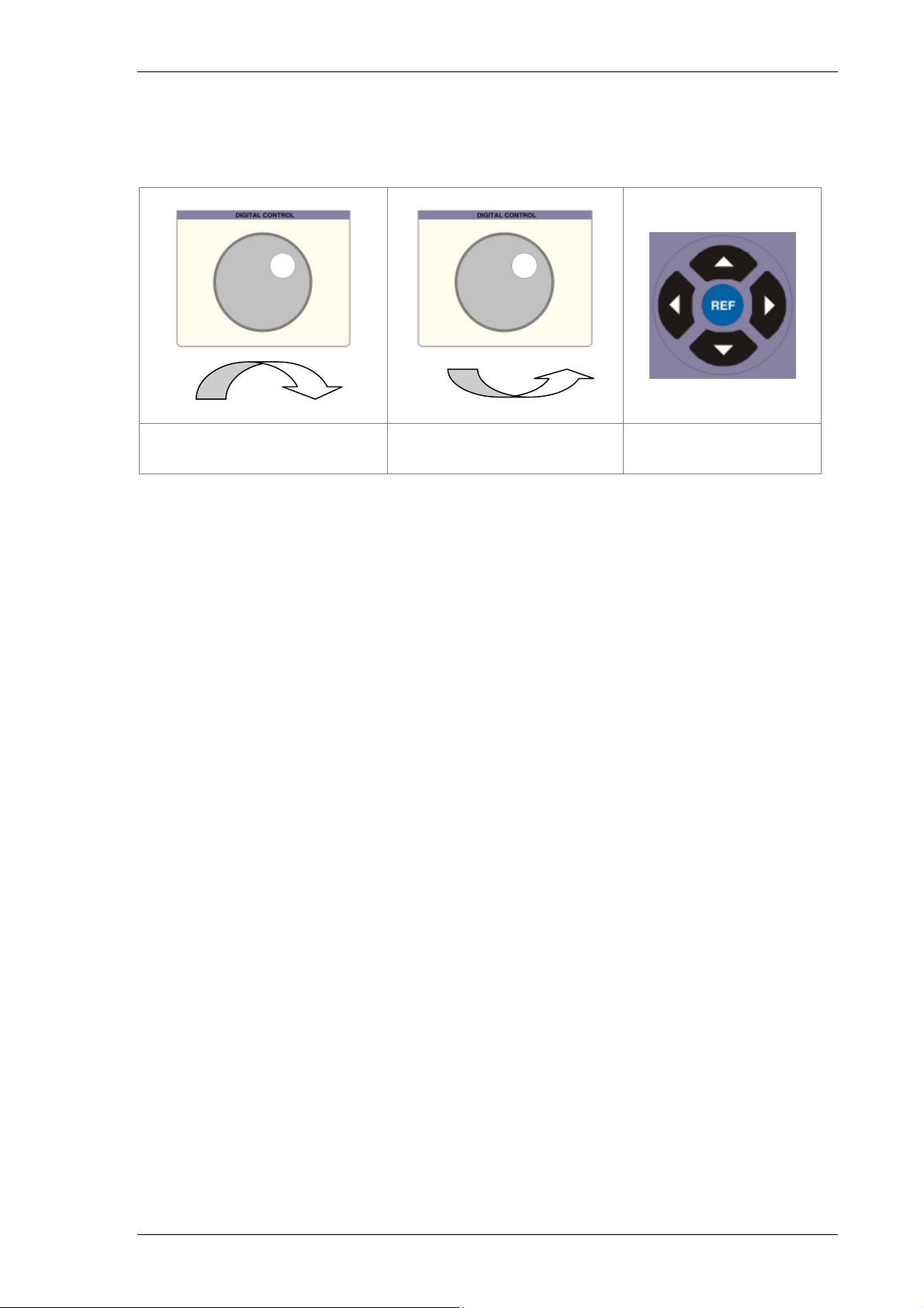
To increase or decrease the highlighted digit, use the up and down of the cursor
keys or use the digital potentiometer.
Clockwise Rotation
(Increment Digit)
Anti-Clockwise Rotation
(Decrement Digit)
Up / Down
Cursor Buttons
Note: The thermocouple type, temperature and cold junction compensation settings
can be changed at any time by re-entering / selecting the setting required
TRANSMILLE LTD. Version 5.00: February 2011 Page 42
Page 43
3000A SERIES OPERATION MANUAL
Special Functions Available using the ‘soft’ keys
The ‘soft’ keys are positioned directly under the display and the function of these
keys will change depending on the parameter of the calibrator. The calibrator’s
parameters can be accessed by scrolling through the menus by using the NEXT key
to go to the next level of functions and the EXIT key to return to the previous level.
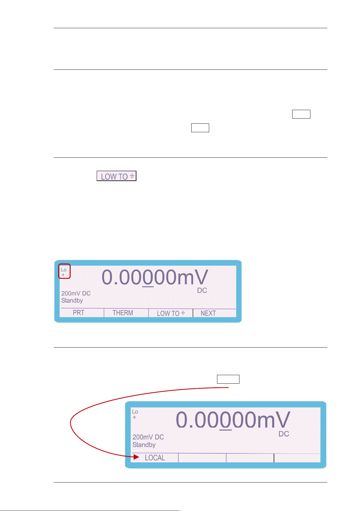
Connecting Output Negative to line earth (ground)
The soft key switches the output negative terminal from floating to
ground (line earth). The ‘on’ condition is shown at the top left of the display and also
by the front panel LED.
We recommend that the default condition of output connected to ground is used as
this reduces noise and pick up and decreases the risk of damage to the calibrator by
incorrect connection.
Selecting front panel control
When the calibrator has been controlled from the interface, the front panel controls
are disabled. To regain front panel control use the LOCAL soft key
TRANSMILLE LTD. Version 5.00: February 2011 Page 43
Page 44

3000A SERIES OPERATION MANUAL
Setting TTL Logic Frequency Output.
Note: The calibrator uses a precision Temperature Compensated Crystal Oscillator
(TCXO). Frequencies from 1Hz to 1MHz in 1Hz steps are available together with
the reference frequency of 10MHz.
1) Select FREQ using the soft key
2) Press the numeric keys to enter the required value, e.g. 123456
3) Press
4) Press
Frequency output from
FREQ/TRG BNC socket
To increase or decrease the highlighted digit, use the up and down of the cursor
keys or use the digital potentiometer.
Clockwise Rotation
(Increase Frequency )
TRANSMILLE LTD. Version 5.00: February 2011 Page 44
Anti-Clockwise Rotation
(Decrease Frequency)
Up / Down
Cursor Buttons
Page 45
3000A SERIES OPERATION MANUAL
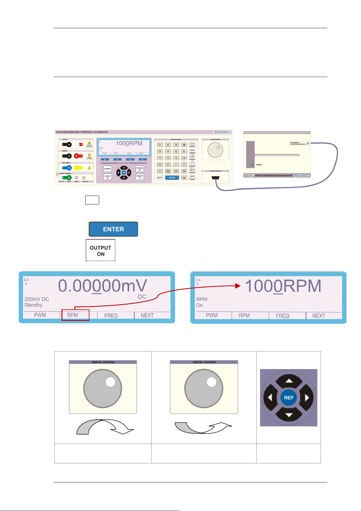
Setting RPM Output with EA003 Adaptor (Option)
Note: The calibrator uses a precision Temperature Compensated Crystal Oscillator
(TCXO). Using the EA003 Optical Tachometer Calibration Adaptor the RPM can be
set from 60 to 60000 RPM in 1 RPM steps.
1) Select RPM using the soft key
2) Press the numeric keys to enter the required value, e.g. 1000
3) Press
4) Press
To increase or decrease the highlighted digit, use the up and down of the cursor
keys or use the digital potentiometer.
Clockwise Rotation
(Increase RPM )
TRANSMILLE LTD. Version 5.00: February 2011 Page 45
Anti-Clockwise Rotation
(Decrease RPM)
Up / Down
Cursor Buttons
Page 46
3000A SERIES OPERATION MANUAL
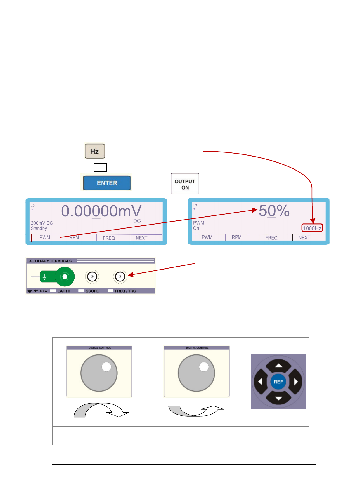
Setting PWM (Mark Space Ratio)
The calibrator can produce an accurate mark space ratio output within the frequency
range 100Hz to 10kHz. The width of the pulse can be adjusted from 1% to 99% in
1% steps.
1) Select PWM using the soft key
2) Press the numeric keys to enter the required value, e.g. 1000
3) Press to determine the frequency
4) Press PWM, use the numeric pad to enter the required %, e.g. 50
5) Press followed by
Pulse Width Modulated output from
FREQ/TRG BNC socket
To increase or decrease the highlighted digit, use the up and down of the cursor
keys or use the digital potentiometer.
Clockwise Rotation
( Increase pulse width)
TRANSMILLE LTD. Version 5.00: February 2011 Page 46
Anti-Clockwise Rotation
(Decrease pulse width)
Up / Down
Cursor Buttons
Page 47
3000A SERIES OPERATION MANUAL
V
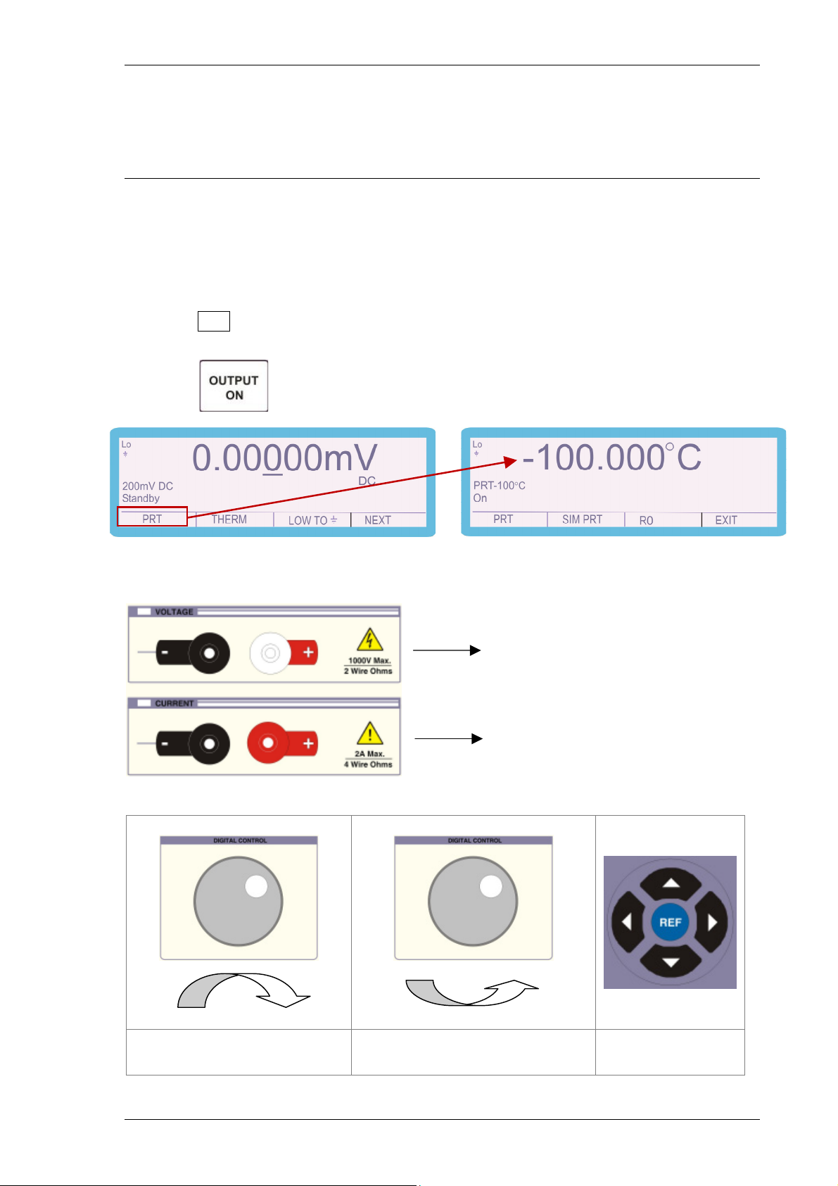
Selecting PRT (PT100) Resistance Output (Option)
The calibrator uses fixed value standard resistors. These resistors represent the
following temperatures: -100°C, 0°C, 30°C, 60°C, 100°C, 200°C, 300°C and 800°C.
The nearest available temperature to the entered value will be selected.
1) Select PRT using the soft key
2) Use up / down arrow keys or the rotary control to select the required temperature.
3) Press
4 Wire output is from the Voltage & Current terminals
oltage (Sense)
Current
Clockwise Rotation
(Next PRT Point)
TRANSMILLE LTD. Version 5.00: February 2011 Page 47
Anti-Clockwise Rotation
(Previous PRT Point)
Up / Down
Cursor Buttons
Page 48
3000A SERIES OPERATION MANUAL
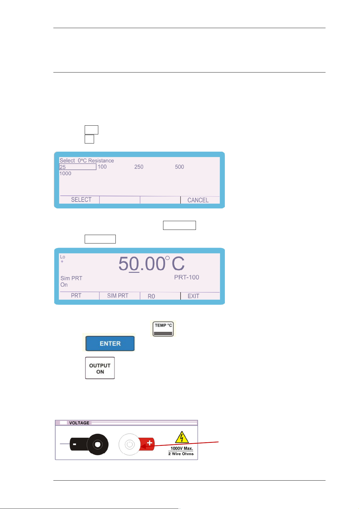
Selecting Simulated PRT (RO) Output (Option)
The calibrator can simulate PRT temperature values for RTD types 25Ω,100Ω,
250Ω, 500Ω and 1000Ω in the range -200°C to 800°C
1) Select PRT using the soft key
2) Select RO using the soft key, the following screen appears
Use the arrow keys, up and down, left and right to place the highlighted box over the
RTD type required and then press SELECT
3) Select SIM PRT using the soft key to display the screen below
4) Press the numeric keys to enter the required value, e.g. 50
5) Press the function key e.g.
6) Press
7) Press
Simulated PRT – 2 wire output via voltage terminals
Voltage output terminals
TRANSMILLE LTD. Version 5.00: February 2011 Page 48
Page 49
3000A SERIES OPERATION MANUAL
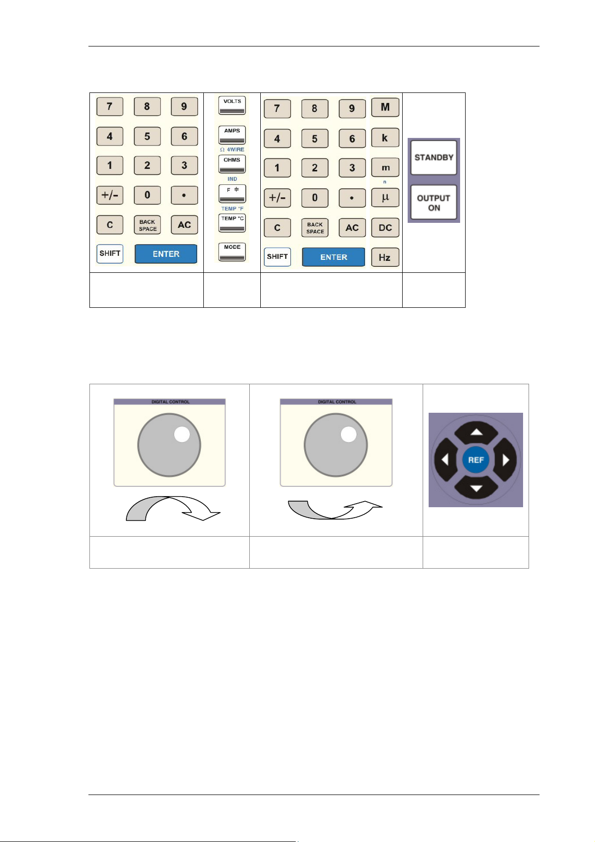
Select
Output On
Key in
Temperature Value
Select
Function
Press
Enter
To increase or decrease the highlighted digit, use the up and down of the cursor
keys or use the digital potentiometer.
Clockwise Rotation
(Increase temperature)
Anti-Clockwise Rotation
(decrease temperature)
Up / Down
Cursor Buttons
TRANSMILLE LTD. Version 5.00: February 2011 Page 49
Page 50
3000A SERIES OPERATION MANUAL
Selecting AC Power Calibration Output (Option)
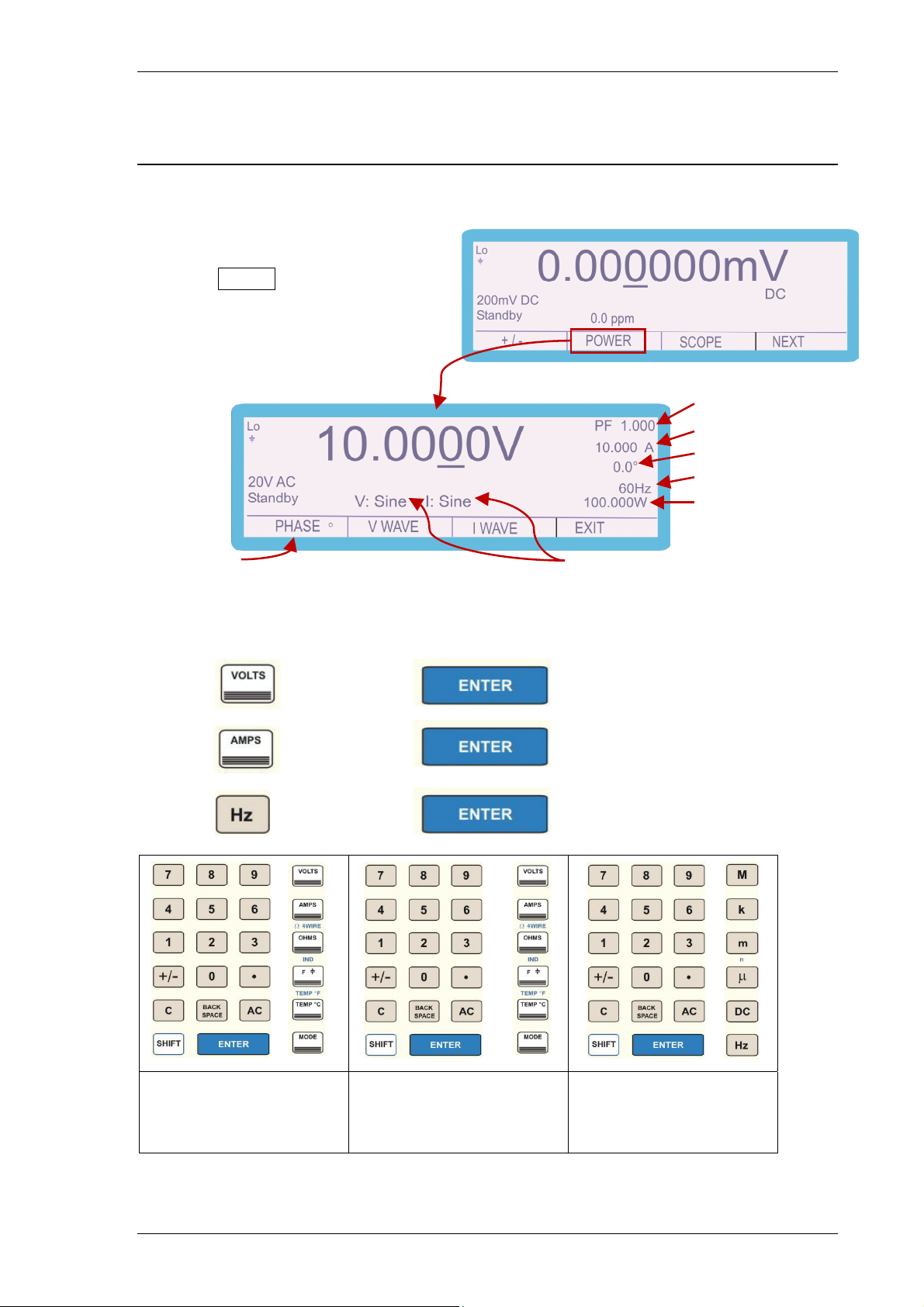
The Calibrator can simulate power by simultaneously supplying AC voltage and AC
current with a phase relationship.
1) Select POWER using the soft key
Power Factor
Current Output
Phase
Frequency
Power
Change Phase Waveform type (voltage and current)
(3041A & 3010A Power DSS option)
2) Press the numeric keys to enter the required value (voltage), e.g. 10
3) Press and then press
4) Press the numeric keys to enter the required value (current) e.g. 10
5) Press and then press
6) Press the numeric keys to enter the required value (frequency) e.g. 60
7) Press and then press
Enter Voltage value
followed by VOLTS
Press ENTER
TRANSMILLE LTD. Version 5.00: February 2011 Page 50
Enter Current value
Followed by AMPS
Press ENTER
Enter Frequency value
Followed by Hz
Press ENTER
Page 51
3000A SERIES OPERATION MANUAL
Note: Current output in power mode follows the same convention as normal
current operation –
Up to 2A is output from the low current terminals
2.02 – 30A (20A for 3050) output from the
high current terminals
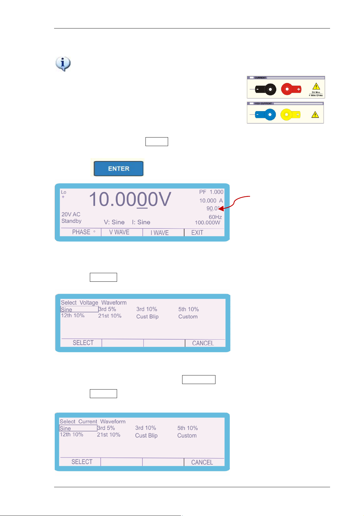
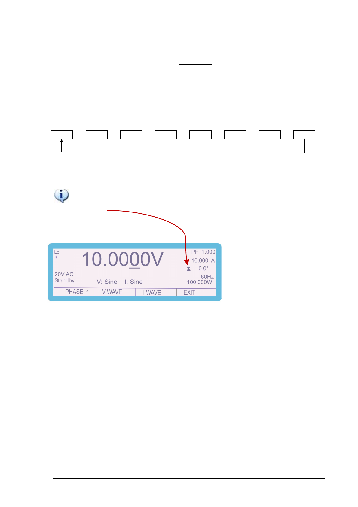
8) To change phase, select PHASE using the soft key
9) Press the numeric keys to enter the required value (voltage), e.g. 90
10) Press
Phase
For DDS Power Option ONLY
Select the voltage and current waveforms as follows:
11) Select V WAVE using the soft key and the screen below will appear
Use the arrow keys, up and down, left and right to place the highlighted box over the
waveform type required and then press SELECT
12) Select I WAVE using the soft key and the following screen will be displayed
TRANSMILLE LTD. Version 5.00: February 2011 Page 51
Page 52
3000A SERIES OPERATION MANUAL
3
5
2
Use the arrow keys, up and down, left and right to place the highlighted box over the
waveform type required and then press SELECT
The CUSTOM waveform item is user programmable using the ProWave software
supplied with the calibrator. See the ProWave documentation for more details on
setting the custom waveform.
SINE SQUARE
TRIANGLE
RD 10%
TH 10%
1ST 10% USER&SINE USER WAVE
Use the Output On / Standby buttons to control the output
Note: When the hourglass is shown in the calibrator display, phase
correction is in progress, and calibrator will not respond until completed and
the hourglass disappears.
TRANSMILLE LTD. Version 5.00: February 2011 Page 52
Page 53
3000A SERIES OPERATION MANUAL
Selecting DC Power Calibration Output (Option)
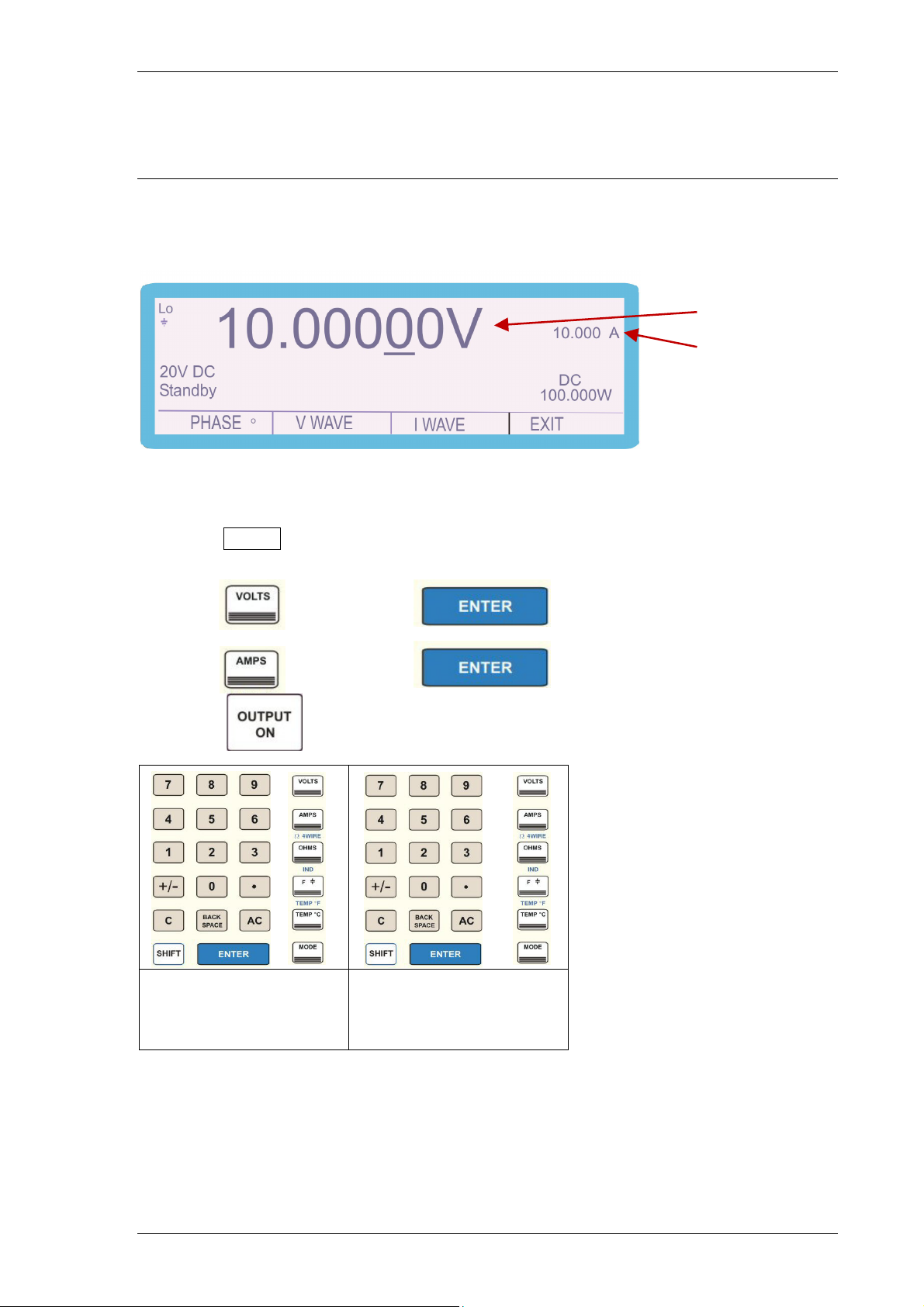
The calibrator can simulate DC power by simultaneously outputting DC voltage and
DC current.
Voltage display
Current display
To configure power calibration mode:
1) Select POWER using the soft key
2) Press the numeric keys to enter the required value (voltage), e.g. 10
3) Press and then press
4) Press the numeric keys to enter the required value (current) e.g. 10
5) Press and then press
6) Press
Enter Voltage value
Enter Current value
followed by VOLTS
Press ENTER
TRANSMILLE LTD. Version 5.00: February 2011 Page 53
Followed by AMPS
Press ENTER
Page 54
3000A SERIES OPERATION MANUAL
Selecting Oscilloscope Calibration Output (Option)
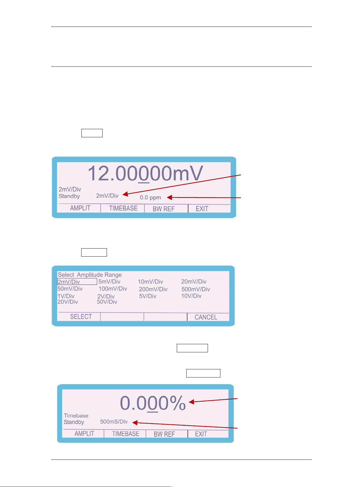
The calibrator provides Amplitude, Timebase and Bandwidth outputs for calibration
of oscilloscopes.
To configure oscilloscope calibration mode:
1) Select SCOPE using the soft key
2) Calibrator will select AMPLIT(UDE) mode.
Use the RANGE UP / RANGE
DOWN buttons to change range.
Use the digital control to alter the
deviation (clockwise to increase,
anti-clockwise to decrease).
3) Use the RANGE UP or RANGE DOWN buttons to change range or
4) Select AMPLIT using the soft key and the following screen will appear
Use the arrow keys, up and down, left and right to place the highlighted box over the
amplitude range required and then press SELECT
To alter the deviation, use the up / down arrow buttons or digital control.
5) To select Timebase mode press soft key TIMEBASE
Use the digital control to alter the
deviation (clockwise to increase,
anti-clockwise to decrease).
Use the RANGE UP / RANGE
DOWN buttons to change range.
TRANSMILLE LTD. Version 5.00: February 2011 Page 54
Page 55
3000A SERIES OPERATION MANUAL
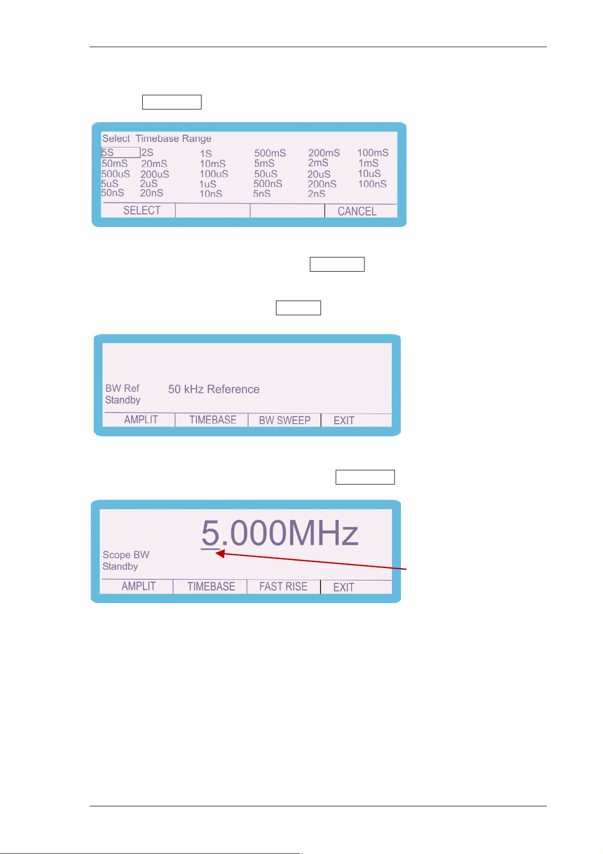
6) Use the RANGE UP or RANGE DOWN buttons to change range or
7) Select TIMEBASE using the soft key and the following screen will appear
Use the arrow keys, up and down, left and right to place the highlighted box over the
amplitude range required and then press SELECT
To alter the deviation, use the up / down arrow buttons or digital control.
8) For Bandwidth function use the BW REF soft key the following screen will appear.
50kHz reference output
is available.
9) To select Bandwidth Sweep mode use the BW SWEEP soft key.
Use the digital potentiometer to alter
the output (clockwise to increase,
anti-clockwise to decrease)
To select the highlighted digit, use the left/right arrow buttons. To change the output,
use the up / down arrow buttons or use the digital potentiometer.
Maximum frequency available depends on option fitted:
a) 250MHz (Option SCP250 – 3050A Calibrator)
b) 350MHz (Option SCP350 – 3041A and 3010A Calibrators)
c) 600MHz (Option SCP600 – 3041A and 3010A Calibrators)
TRANSMILLE LTD. Version 5.00: February 2011 Page 55
Page 56
3000A SERIES OPERATION MANUAL
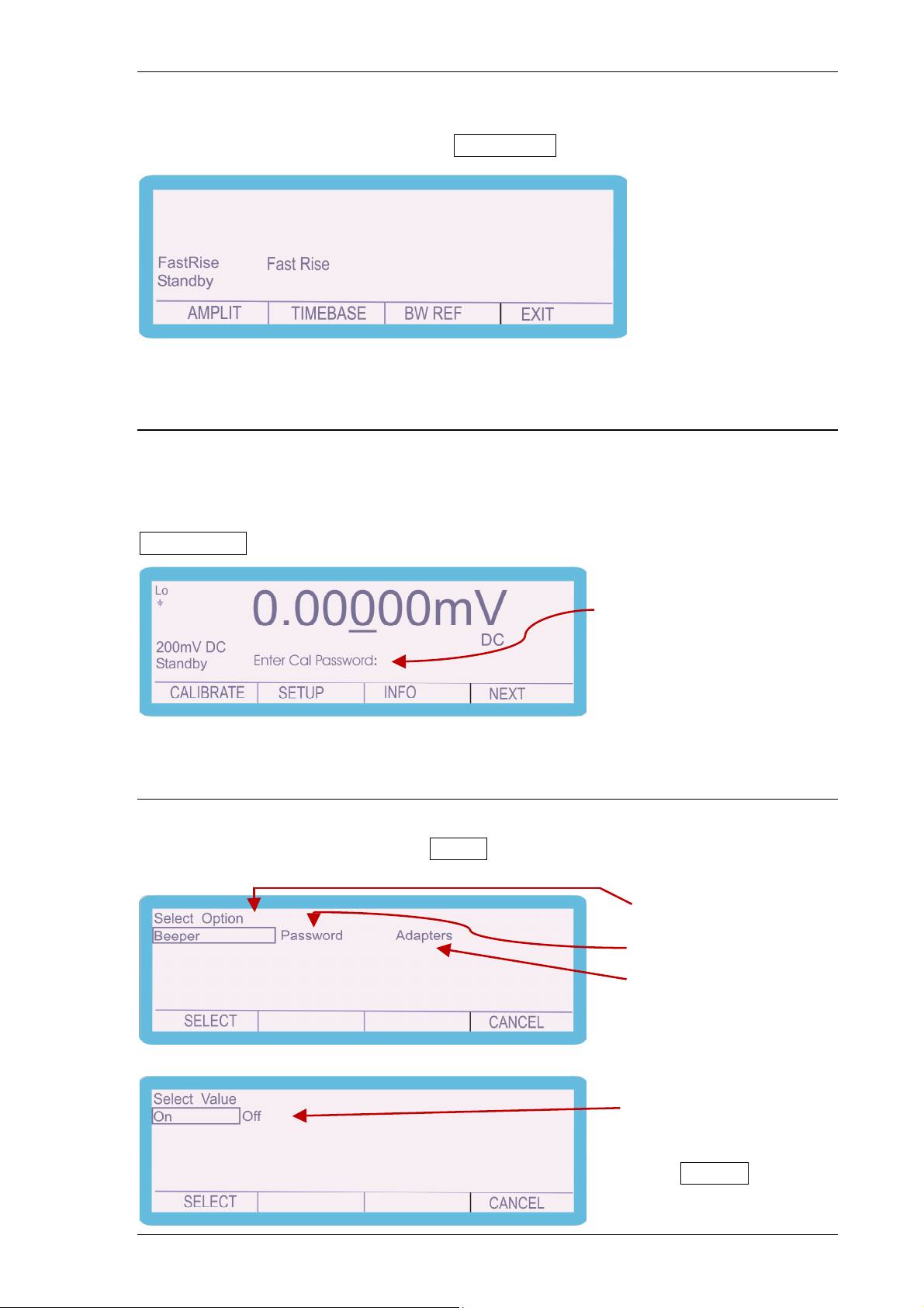
10) To select Fast Rise mode use the FAST RISE soft key.
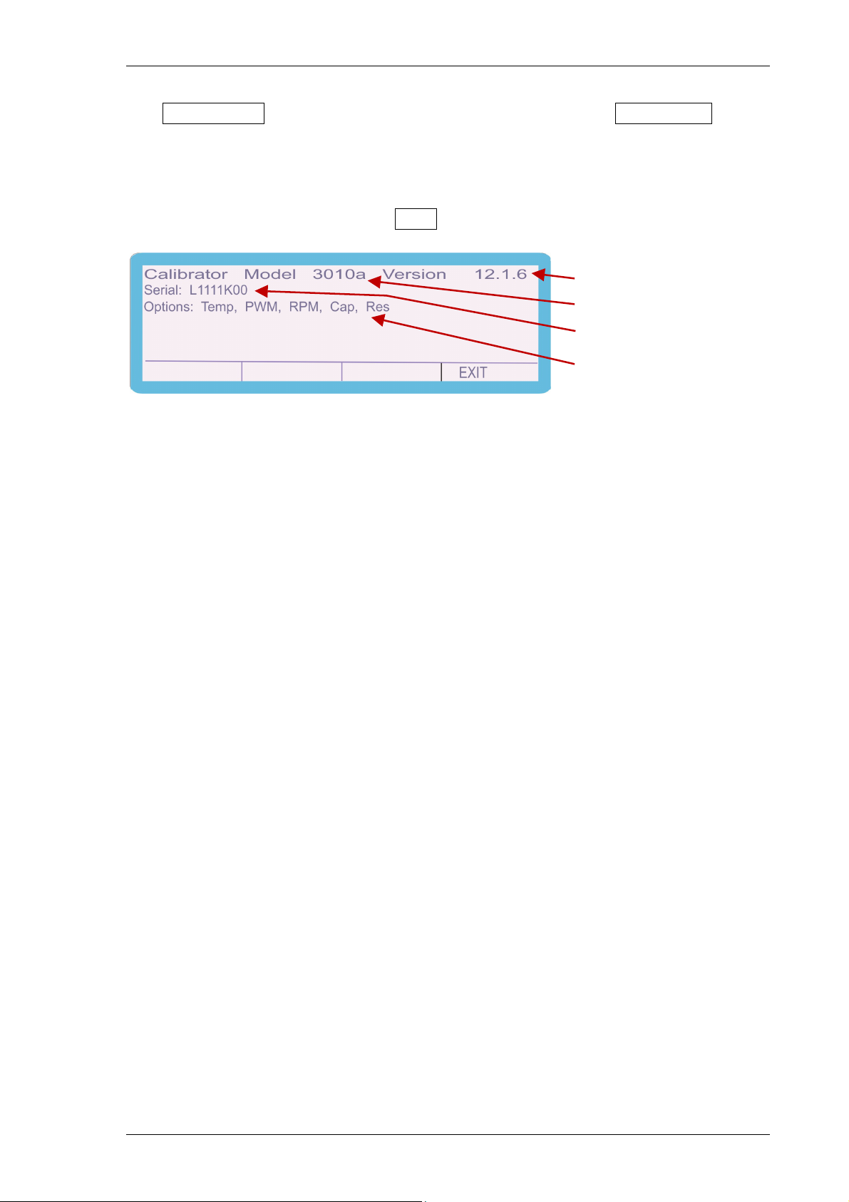
Calibrate
The calibrator can be calibrated via the front panel; further details of this function are
detailed in the service manual. To access to the calibration menu press the
CALIBRATE soft key and enter the password.
Enter password
Setup (Beeper / Password / Adapters)
Enter the setup menu by press the SETUP soft key, the following screen will appear.
Beeper on or off
Password
Configure Adaptors
Beeper screen, choose
On or Off using the left
& right arrow keys, then
press SELECT
TRANSMILLE LTD. Version 5.00: February 2011 Page 56
Page 57
3000A SERIES OPERATION MANUAL
The PASSWORD function is outlined in the service manual and ADAPTORS
function is detailed in the appropriate manual for each adaptor.
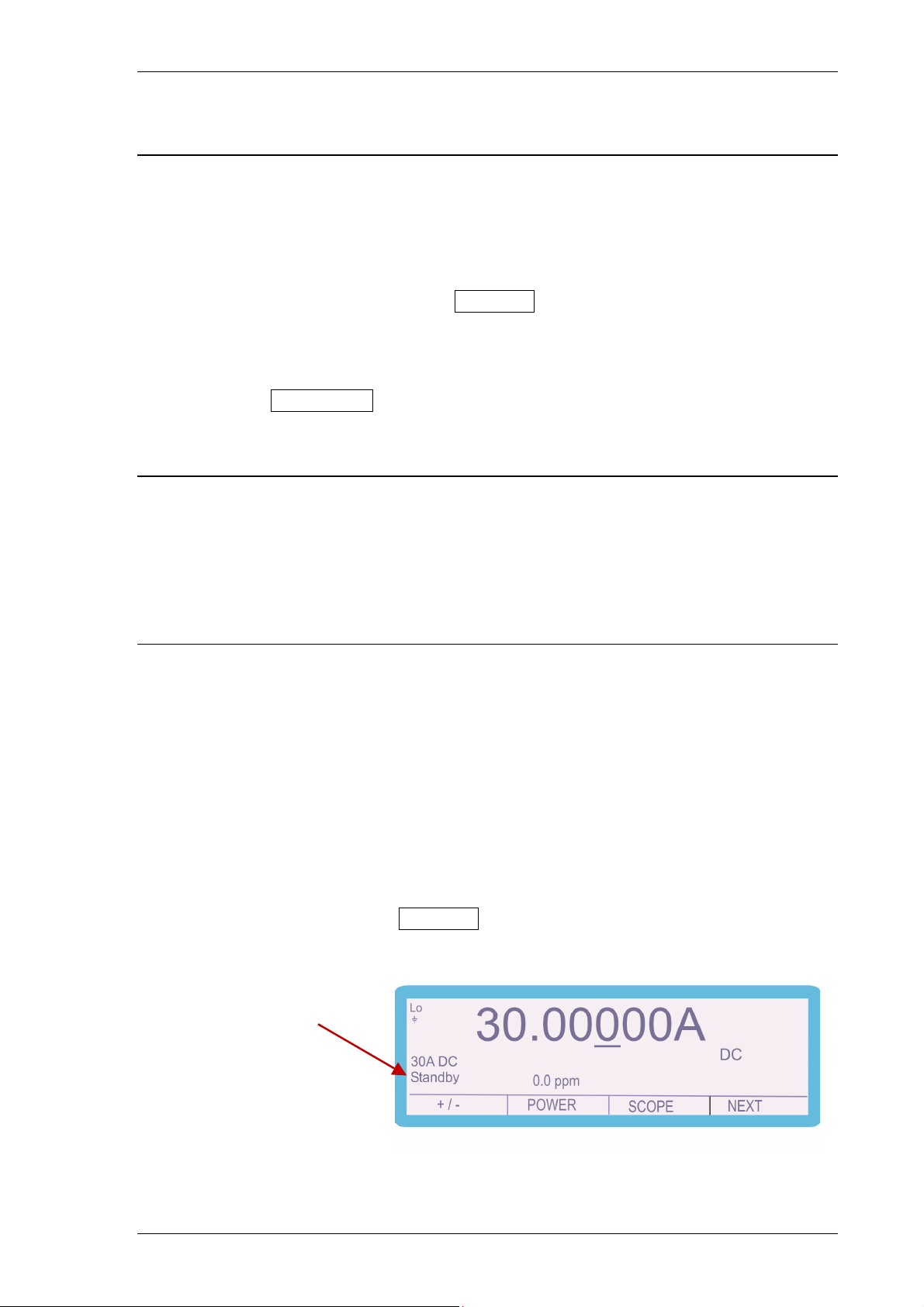
Info
Enter the setup menu by press the INFO soft key, the following screen will appear.
Firmware version
Model type
Instrument Serial No.
Options fitted
The info(rmation) screen shows the Calibrator type, Firmware version, Serial
number and Options fitted (this will vary depending on the model and additional
features).
TRANSMILLE LTD. Version 5.00: February 2011 Page 57
Page 58
3000A SERIES OPERATION MANUAL
Warning and output Overload indications.
The self-test function of the 3000A series calibrator continuously monitors the output
of the calibrator for overload or fault conditions.
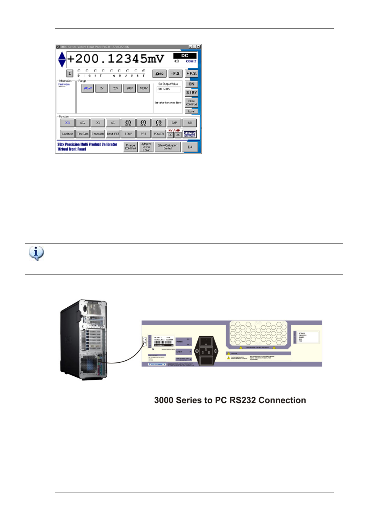
In the event of the calibrator not being able to drive the load, it will automatically trip
into standby and the display will show Standby. The ‘standby’ condition is caused
by the required drive current being too high on a voltage range or the required
compliance voltage being too high on a current range. The output can be restored
by pressing the Output On key after the load has been corrected.
High Voltage Timeout.
As an additional safety feature, the calibrator will automatically return to standby if
left on the 200V or 1kV ranges after a set time period. This is 20 minutes for DC and
AC frequencies of less than 5 kHz or 3 minutes for frequencies of 5 kHz and greater.
30 Amp Temperature Cut-out
The 3000A Series calibrators are capable of supplying high currents for a sustained
periods up to 30A (20A for 3050A) – above this value the calibrator will enter a
standby / cool-down period after a set amount of time depending on the output set.
The output amplifier operating temperature is monitored by the micro controller
which will shut down the output if required. The time before shut down occurs will
vary depending on the set output current and the load - see extended specifications.
During this shutdown period, the calibrator will be set to standby with a warning
message shown on the display Standby. It is safe to reselect the output at any time
as the microprocessor will automatically protect the output amplifier from damage.
Output to standby
TRANSMILLE LTD. Version 5.00: February 2011 Page 58
Page 59

3000A SERIES OPERATION MANUAL
Interface Types
Connection to the 3000A Series calibrators is achieved by the following interfaces:
RS232
9 Way ‘D’ type female connections
USB (included)
USB connection using COM to USB conversion using supplied adapter.
TRANSMILLE LTD. Version 5.00: February 2011 Page 59
Page 60

3000A SERIES OPERATION MANUAL
RS232 Interface
The calibrator can be fully controlled and calibrated via the bi-directional RS232
interface. The interface uses the standard 9 pin PC connector (or USB adaptor) and
a standard serial lead. The interface is optically isolated from the calibrator circuitry.
Baud rate is fixed at 9600 baud, no parity and one stop bit which allows a complete
output command to be sent in less than 20ms. The calibrator can send information
with reference to the output status, calibration factors and value of internal
standards together with other information. The internal processor decodes the
commands and returns control codes to verify the correct operation of that
command.
The calibrator can be sent individual commands directly from a Windows HYPER
TERMINAL program, any basic or high level program, the virtual front panel (VFP)
program, or from the ProCal Calibration System.
Configuring the COM port
To allow communication from PC based programs, these programs must be
configured to the following settings:
BAUD RATE : 9600
PARITY : NONE
DATA BITS : 8
STOP BITS : 1
TRANSMILLE LTD. Version 5.00: February 2011 Page 60
Page 61
3000A SERIES OPERATION MANUAL
The 3000A series Virtual Front Panel software (optional) from Transmille comes pre-
configured with these settings, however if you are using another program these
settings will need to be verified before proceeding to control the 3000A Series
calibrators.
The RS232 connection is made using a straight-through type cable - this is supplied
as standard with all 3000A Series calibrators.
DO NOT USE A NULL MODEM TYPE CABLE AS PINS 2 & 3 ARE REVERSED
AND THE CALIBRATOR WILL NOT RESPOND TO COMMANDS
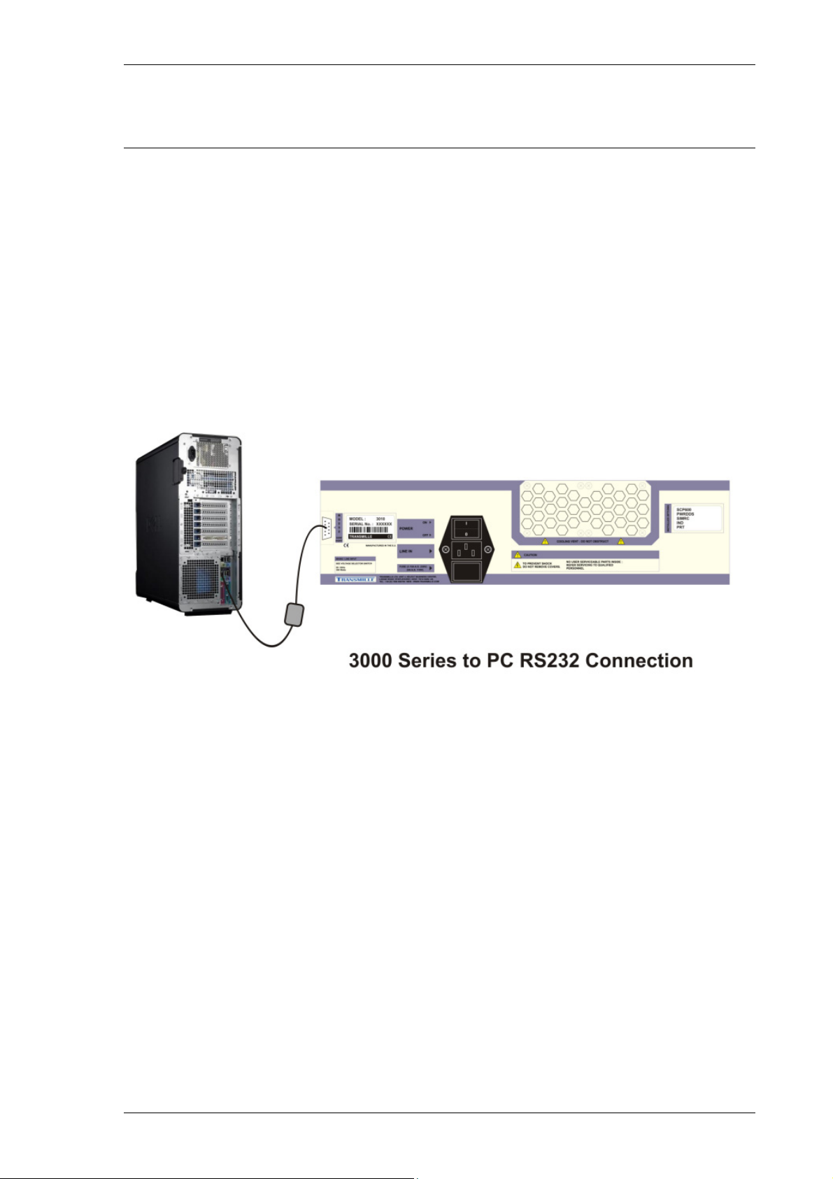
Connect the RS232 Interface from the 9 Way ‘D’ type connector on the
rear of the PC to the 9 Way ‘D’ type connector on the 3000A Series
calibrator.
TRANSMILLE LTD. Version 5.00: February 2011 Page 61
Page 62
3000A SERIES OPERATION MANUAL
USB Interface
By using an RS232 to USB converter, the 3000A Series calibrators
can be connected to the host PC via the USB port. This option will be
provided as an additional compact unit and software driver.
The RS232 to USB converter will simulate a normal COM port (the
next available free COM port number, usually COM3 upwards) - this is
especially useful for Laptop/Notebooks, where the traditional RS232
COM port has been replaced by one or more USB ports.
Connect the USB Interface from the USB type connector on the
rear of the PC to the 9 Way ‘D’ type connector on the 3000A
Series calibrator via the RS232 to USB converter.
TRANSMILLE LTD. Version 5.00: February 2011 Page 62
Page 63

3000A SERIES OPERATION MANUAL
Remote Programming
WARNING
The 3000A series calibrators can produce high voltages up to
1025V and must be programmed with due caution to prevent
dangerous voltages from being present at the output terminals
without warning to the operator.
Any programs should be extensively tested to maintain safe
operation and include safeguard’s such as error catchments and
handling to ensure that any commands sent to the calibrator
perform as expected and any that do not are safely handled to
ensure user safety.
Within the 3000A series command language, response codes are
included to determine the operational state of the calibrator. These
response codes can also be used to determine whether a
command was received correctly and thus ensuring safe operation
of the calibrator.
TRANSMILLE LTD. Version 5.00: February 2011 Page 63
Page 64

3000A SERIES OPERATION MANUAL
Programming Commands Overview
The 3000A Series calibrators are controlled by a set of simple high level commands
which can be used either individually or as part of a command sequence.
The commands can be joined together using the / (forward slash) character.
The required terminator for the commands to be detected by the calibrator is a
carriage return (ASCII character 13) and should be the last character sent on a
command line.
For Example:
Command1/Command2 <CR>
Where each command is represented as Commandx
(x being the command number)
and the carriage return (ASCII character 13) is represented by <CR>
TRANSMILLE LTD. Version 5.00: February 2011 Page 64
Page 65

3000A SERIES OPERATION MANUAL
RESPONSE CODES
The 3000A Series calibrators will respond to any command with a fixed code
beginning with an star (*) - the codes are listed below
Response Code Description
*0 OK
*1 ERROR IN COMMAND LINE
*2 ERROR IN RANGE COMMAND
*3 ERROR IN FREQUENCY COMMAND
*4 ERROR IN O/P COMMAND
*5 ERROR IN CAL FACTOR SENT
*6 ERROR IN CAL FACTOR COMPARE
*7 COMMAND OUT OF RANGE ( A1,A2 ETC ) OR
PASSWORD NOT SET
*8 30A/HV TIMEOUT or OVER TEMPERATURE
*9 OUTPUT ERROR
TRANSMILLE LTD. Version 5.00: February 2011 Page 65
Page 66
3000A SERIES OPERATION MANUAL
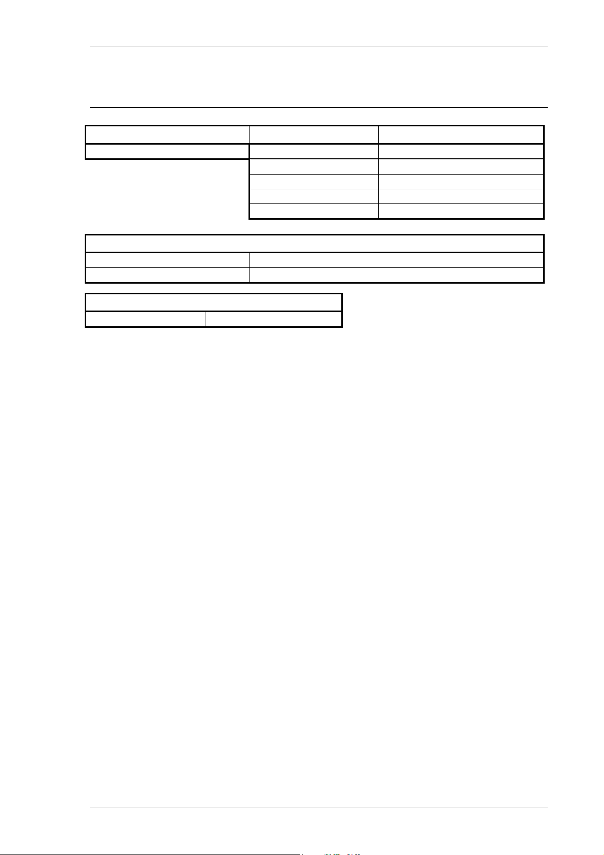
DC Voltage Commands
Function Range Command
DC Voltage 200mV R1
2V R2
20V R3
200V R4
1000V R5
Standby Mode
Standby ON S1
Standby OFF S0
Output
Set Output O (not zero)
The DC voltage section consists of a set of range commands which are used in
conjunction with the standby and output command. To enable a DC Voltage to be
set and an output assigned, the following command sequence should be used:
<RANGE>/<OUTPUT>/<STANDBY CONDITION><CR>
For example, to assign 2V D.C. with the output switched on, the command is:
R2/O2/S0<CR>
R2 = 2V Range (as detailed in the table above)
O2 = 2V Output
S0 = Standby OFF (i.e. output switched ON)
<CR> = Carriage Return (ASCII character 13)
TRANSMILLE LTD. Version 5.00: February 2011 Page 66
Page 67

3000A SERIES OPERATION MANUAL
Additional examples
150mV DC R1/O150/S0<CR> (sets 150mV output on the 200mV range)
22V DC R3/O22/S0<CR> (sets 22V output on the 200V range)
If a command includes a value which cannot be set due to, for example, the value
being higher than the range maximum, the calibrator will reject the command and
stay set as it is (the calibrator will also beep to signify a rejected command)
The calibrator will respond to the commands sent with the response codes as
detailed at the beginning of this section. These codes can be used to ensure that
hazardous output conditions are clearly indicated to the operator and to maintain
control of these outputs. This allows the calibrator to be returned to a safe state
once the testing required has been completed (e.g. setting the calibrator back to
standby once a test is complete and ensuring this has been successfully achieved
and no hazardous outputs remain on the terminals).
This functionality is employed within the ProCal calibration software from Transmille
to allow safe operation of the calibrator and to ensure the calibrator is returned to a
safe state in between test points and at the completion of a test sequence.
TRANSMILLE LTD. Version 5.00: February 2011 Page 67
Page 68
3000A SERIES OPERATION MANUAL
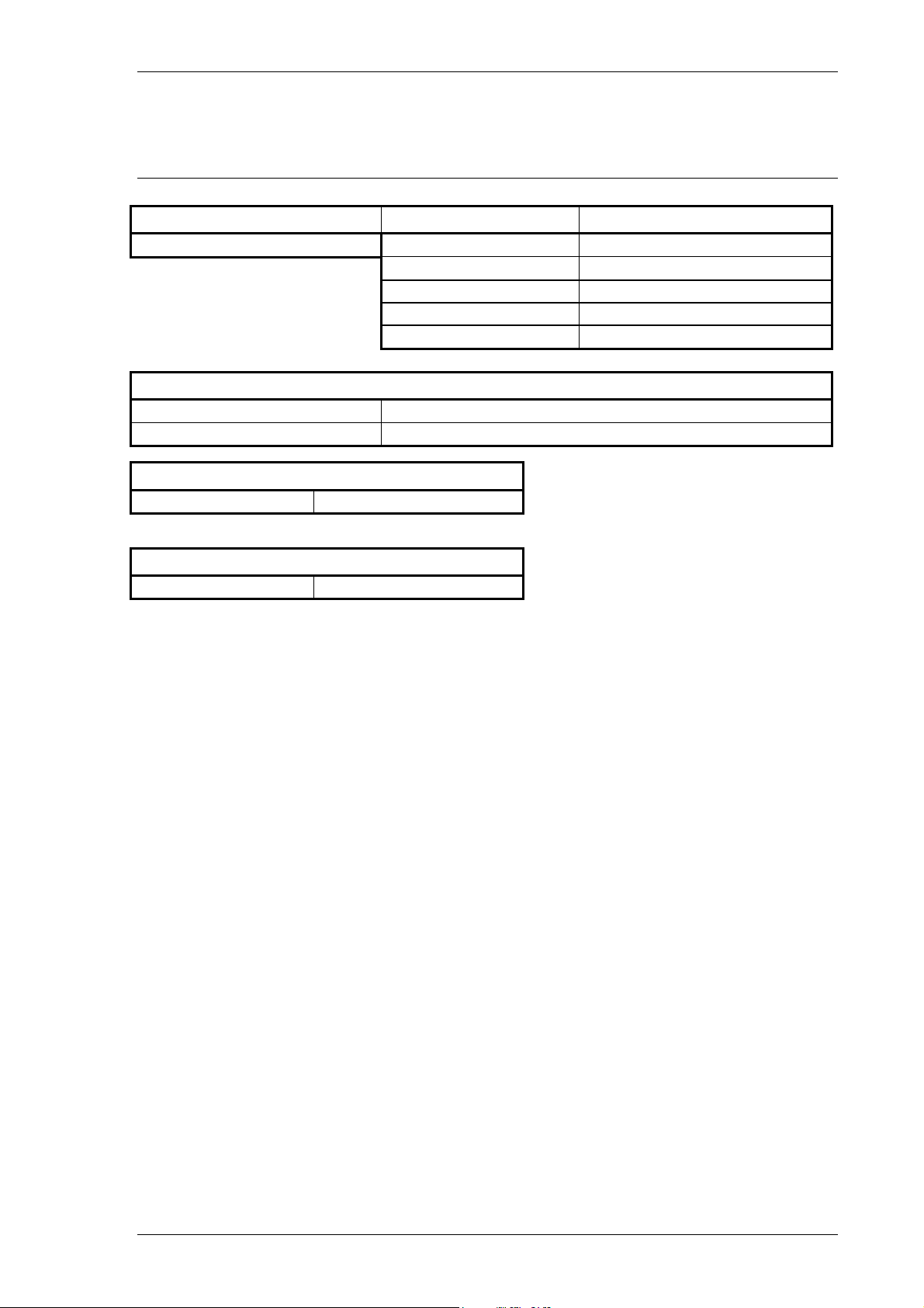
AC Voltage Commands
Function Range Command
AC Voltage 200mV R12
2V R13
20V R14
200V R15
1000V R16
Standby Mode
Standby ON S1
Standby OFF S0
Output
Set Output O (not zero)
AC Frequency
Fxxxxx E.G. 10kHz = F10000
The AC voltage section consists of a set of range commands which are used in
conjunction with the standby and output command. To enable an AC Voltage to be
set and an output assigned, the following command sequence should be used :
<RANGE>/<OUTPUT>/<FREQUENCY>/<STANDBY CONDITION><CR>
For example, to get 2V @ 200Hz AC with the output switched on, the command is:
R2/O2/F200/S0<CR>
R2 = 2V Range (as detailed in the table above)
O2 = 2V Output
F200 = 200Hz Frequency
S0 = Standby OFF (i.e. output switched ON)
<CR> = Carriage Return (ASCII character 13)
TRANSMILLE LTD. Version 5.00: February 2011 Page 68
Page 69

3000A SERIES OPERATION MANUAL
Additional examples
135mV @ 10kHz AC R1/O135/F10000/S0<CR>
(sets 135mV @ 10kHz output on the 200mV range)
255V @ 15kHz AC R3/O255/F15000/S0<CR>
(sets 255V @ 15kHz output on the 1000V range)
If a command includes a value which cannot be set due to, for example, the value
being higher than the range maximum, the calibrator will reject the command and
stay set as it is (the calibrator will also beep to signify a rejected command)
The calibrator will respond to the commands sent with the response codes as
detailed at the beginning of this section. These codes can be used to ensure that
hazardous output conditions are clearly indicated to the operator and to maintain
control of these outputs. This allows the calibrator to be returned to a safe state
once the testing required has been completed (e.g. Setting the calibrator back to
standby once a test is complete and ensuring this has been successfully achieved
and no hazardous outputs remain on the terminals).
This functionality is employed within the ProCal calibration software from Transmille
to allow safe operation of the calibrator and to ensure the calibrator is returned to a
safe state in between test points and at the completion of a test sequence.
TRANSMILLE LTD. Version 5.00: February 2011 Page 69
Page 70
3000A SERIES OPERATION MANUAL
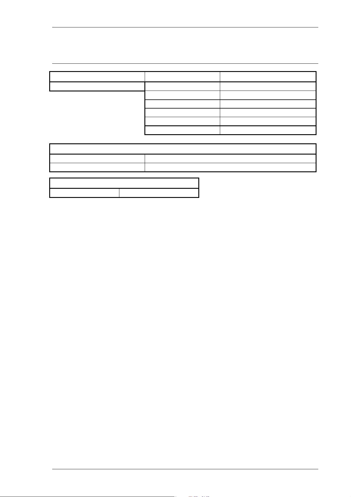
DC Current Commands
Function Range Command
DC Current 200uA R6
2mA R7
20mA R8
200mA R9
2A R10
20A R11
Standby Mode
Standby ON S1
Standby OFF S0
Output
Set Output O (not zero)
The DC current section consists of a set of range commands which are used in
conjunction with the standby and output command. To enable a DC current to be set
and an output assigned, the following command sequence should be used :
<RANGE>/<OUTPUT>/<STANDBY CONDITION><CR>
For example, to get 20mA DC with the output switched on, the command is :
R8/O20/S0<CR>
R8 = 20mA Range (as detailed in the table above)
O2 = 20mA Output
S0 = Standby OFF (i.e. output switched ON)
<CR> = Carriage Return (ASCII character 13)
TRANSMILLE LTD. Version 5.00: February 2011 Page 70
Page 71

3000A SERIES OPERATION MANUAL
Additional examples
25mA DC R9/O25/S0<CR> (sets 25mA output on the 200mA range)
12A DC R11/O12/S0<CR> (sets 12A output on the 20A range)
If a command includes a value which cannot be set due to, for example, the value
being higher than the range maximum, the calibrator will reject the command and
stay set as it is (the calibrator will also beep to signify a rejected command)
The calibrator will respond to the commands sent with the response codes as
detailed at the beginning of this section. These codes can be used to ensure that
hazardous output conditions are clearly indicated to the operator and to maintain
control of these outputs. This allows the calibrator to be returned to a safe state
once the testing required has been completed (e.g. Setting the calibrator back to
standby once a test is complete and ensuring this has been successfully achieved
and no hazardous outputs remain on the terminals).
This functionality is employed within the ProCal calibration software from Transmille
to allow safe operation of the calibrator and to ensure the calibrator is returned to a
safe state in between test points and at the completion of a test sequence.
TRANSMILLE LTD. Version 5.00: February 2011 Page 71
Page 72
3000A SERIES OPERATION MANUAL
AC Current Commands
Function Range Command
AC Current 200uA R17
2mA R18
20mA R19
200mA R20
2A R21
20A R22
Standby Mode
Standby ON S1
Standby OFF S0
Output
Set Output O (not zero)
AC Frequency
Fxxxxx E.G. 10kHz = F10000
The AC current section consists of a set of range commands which are used in
conjunction with the standby and output command. To enable a AC current to be set
and an output assigned, the following command sequence should be
used:
<RANGE>/<OUTPUT>/<FREQUENCY>/<STANDBY CONDITION><CR>
For example, to get 20mA @ 1 kHz AC with the output switched on, the command
is:
R19/O20/F1000/S0<CR>
R19 = 20mA Range (as detailed in the table above)
O2 = 20mA Output
F1000 = 1 kHz Frequency
S0 = Standby OFF (i.e. output switched ON)
<CR> = Carriage Return (ASCII character 13)
TRANSMILLE LTD. Version 5.00: February 2011 Page 72
Page 73

3000A SERIES OPERATION MANUAL
Additional examples
25mA @ 1.5 kHz AC R20/O25/F1500/S0<CR>
(sets 25mA @ 1.5kHz output on the 200mA range)
12A AC @ 300 Hz R22/O12/F300/S0<CR>
(Sets 12A @ 300Hz output on the 20A range)
If a command includes a value which cannot be set due to, for example, the value
being higher than the range maximum, the calibrator will reject the command and
stay set as it is (the calibrator will also beep to signify a rejected command)
The calibrator will respond to the commands sent with the response codes as
detailed at the beginning of this section. These codes can be used to ensure that
hazardous output conditions are clearly indicated to the operator and to maintain
control of these outputs. This allows the calibrator to be returned to a safe state
once the testing required has been completed (e.g. Setting the calibrator back to
standby once a test is complete and ensuring this has been successfully achieved
and no hazardous outputs remain on the terminals).
This functionality is employed within the ProCal calibration software from Transmille
to allow safe operation of the calibrator and to ensure the calibrator is returned to a
safe state in between test points and at the completion of a test sequence.
TRANSMILLE LTD. Version 5.00: February 2011 Page 73
Page 74
3000A SERIES OPERATION MANUAL
Resistance Commands
Function Range Command
Resistance 0 Ohms R23
0.1 Ohms R24
1 Ohms R25
10 Ohms R26
100 Ohms R27
1 kOhm R28
10 kOhms R29
100 kOhms R30
1 MOhms R31
10 MOhms R32
100 MOhms R33
1G Ohms R65
Standby Mode
Standby ON S1
Standby OFF S0
2 / 4 Wire Resistance
2 Wire I0
4 Wire I1
The resistance section consists of a set of range commands which are used in
conjunction with the 2 or 4 Wire mode and standby commands. To enable a DC
resistance to be set, the following command sequence should be used :
<RANGE>/<2 OR 4 WIRE MODE>/<STANDBY CONDITION><CR>
The use of the output (O) command is not necessary as the resistance ranges are
fixed ranges at decade points.
TRANSMILLE LTD. Version 5.00: February 2011 Page 74
Page 75

3000A SERIES OPERATION MANUAL
For example, to set the 1kOhm range 2-Wire output with the output switched on, the
command is:
R28/I0/S0<CR>
R28 = 1KOhm Range (as detailed in the table above)
I0 = 2 Wire mode
S0 = Standby OFF (i.e. output switched ON)
<CR> = Carriage Return (ASCII character 13)
Additional examples
1kOhm 4-Wire R28/I1/S0<CR>
10Mohm 2-Wire R32/I0/S0<CR>
The calibrator will respond to the commands sent with the response codes as
detailed at the beginning of this section. These codes can be used to ensure that
hazardous output conditions are clearly indicated to the operator and to maintain
control of these outputs. This allows the calibrator to be returned to a safe state
once the testing required has been completed (e.g. setting the calibrator back to
standby once a test is complete and ensuring this has been successfully achieved
and no hazardous outputs remain on the terminals).
This functionality is employed within the ProCal calibration software from Transmille
to allow safe operation of the calibrator and to ensure the calibrator is returned to a
safe state in between test points and at the completion of a test sequence.
TRANSMILLE LTD. Version 5.00: February 2011 Page 75
Page 76
3000A SERIES OPERATION MANUAL
Capacitance Commands
Function Range Command
Capacitance 1nF R34
10nF R35
20nF R36
50nF R37
100nF R38
1uF R39
10uF R40
Standby Mode
Standby ON S1
Standby OFF S0
The capacitance section consists of a set of range commands which are used in
conjunction with the standby command. To enable a capacitance to be set, the
following command sequence should be used:
<RANGE>/<STANDBY CONDITION><CR>
The use of the output (O) command is not necessary as the capacitance ranges are
fixed ranges at decade points.
For example, to set the 10nF output with the output switched on, the command is :
R35/S0<CR>
R28 = 10nF Range (as detailed in the table above)
S0 = Standby OFF (i.e. output switched ON)
<CR> = Carriage Return (ASCII character 13)
TRANSMILLE LTD. Version 5.00: February 2011 Page 76
Page 77
3000A SERIES OPERATION MANUAL
Simulated Resistance Commands (Option)
Function Mode Activation Command
Simulated Resistance
Range Command Output
10 Ohms – 99.9 Ohms R27 Ohms
100 Ohms – 999 Ohms R28 kOhms
1kOhms – 9.99kOhms R29 kOhms
10kOhms – 99.9kOhms R30 kOhms
100kOhms – 999kOhms R31 MOhms
1MOhms – 9.99MOhms R32 MOhms
Standby Mode
Standby ON S1
Standby OFF S0
I2
Output
Set Output O (not zero)
The resistance section consists of a set of range commands which are used in
conjunction with the standby command. To enable a capacitance to be set, the
following command sequence should be used :
<FUNCTION>/<RANGE>/<OUTPUT>/<STANDBY CONDITION><CR>
Examples :
8kOhms 5MOhms 60 Ohms
I2/R29/O8/S0<CR> I2/R33/O12/S0<CR> I2/R27/O60/S0<CR>
I2 = Simulated Resistance Function
R29 = 1kOhms – 9.99kOhms Range
O8 = 8 kohms Output
S0 = Standby OFF (i.e. output ON)
<CR> = Carriage Return (ASCII 13)
150Ohms 500kOhms
I2/R28/O0.15/S0<CR> I2/R31/O0.5/S0<CR>
I2 = Simulated Resistance Function
R28 = 100 Ohms – 999 Ohms Range
O0.15 = 0.15kOhms (150 Ohms) O/P
S0 = Standby OFF (i.e. output ON)
<CR> = Carriage Return (ASCII 13)
I2 = Simulated Resistance Function
R32 = 1MOhms – 9.99 MOhms Range
O5 = 5 MOhms Output
S0 = Standby OFF (i.e. output ON)
<CR> = Carriage Return (ASCII 13)
I2 = Simulated Resistance Function
R31 = 100kOhms – 999kOhms Range
O0.5 = 0.5MOhms (500kOhms) O/P
S0 = Standby OFF (i.e. output ON)
<CR> = Carriage Return (ASCII 13)
I2 = Simulated Resistance Function
R27 = 10 Ohms – 99.9 Ohms Range
O60 = 60 Ohms Output
S0 = Standby OFF (i.e. output ON)
<CR> = Carriage Return (ASCII 13)
TRANSMILLE LTD. Version 5.00: February 2011 Page 77
Page 78
3000A SERIES OPERATION MANUAL
Simulated Capacitance Commands (Option)
Function Range Command
Capacitance 100uF R41
1mF R67
10mF R68
Standby Mode
Standby ON S1
Standby OFF S0
The capacitance section consists of a set of range commands which are used in
conjunction with the standby command. To enable a capacitance to be set, the
following command sequence should be used :
<RANGE>/<STANDBY CONDITION><CR>
The use of the output (O) command is not necessary as the capacitance ranges are
fixed ranges at decade points.
For example, to set the 1mF output with the output switched on, the command is :
R41/S0<CR>
R41 = 100uF Range (as detailed in the table above)
S0 = Standby OFF (i.e. output switched ON)
<CR> = Carriage Return (ASCII character 13)
TRANSMILLE LTD. Version 5.00: February 2011 Page 78
Page 79

3000A SERIES OPERATION MANUAL
Additional examples
1mF R67/S0<CR>
10mF R68/S0<CR>
The calibrator will respond to the commands sent with the response codes as
detailed at the beginning of this section. These codes can be used to ensure that
hazardous output conditions are clearly indicated to the operator and to maintain
control of these outputs. This allows the calibrator to be returned to a safe state
once the testing required has been completed (e.g. setting the calibrator back to
standby once a test is complete and ensuring this has been successfully achieved
and no hazardous outputs remain on the terminals).
This functionality is employed within the ProCal calibration software from Transmille
to allow safe operation of the calibrator and to ensure the calibrator is returned to a
safe state in between test points and at the completion of a test sequence.
TRANSMILLE LTD. Version 5.00: February 2011 Page 79
Page 80
3000A SERIES OPERATION MANUAL
TTL Frequency Commands (Option)
Function Mode Activation Command
TTL Frequency R58
Preset Values Command
1Hz H0
10Hz H1
100Hz H2
1kHz H3
10kHz H4
20kHz H5
50kHz H6
100kHz H7
1MHz H8
10MHz H9
Standby Mode
Standby ON S1
Standby OFF S0
The TTL frequency section consists of a mode activation command followed by a
set of range commands which are used in conjunction with the standby command.
To enable a TTL frequency to be set, the following command sequence should be
used:
<MODE>/<PRESET OR (O) FREQUENCY>/<STANDBY CONDITION><CR>
The use of the output (O) command enables the frequency to be set from 1Hz to
1MHz in 1Hz steps.
TRANSMILLE LTD. Version 5.00: February 2011 Page 80
Page 81

3000A SERIES OPERATION MANUAL
For example, to set the 10 kHz output with the output switched on, the command
would be:
R58/H4/S0<CR>
R58 = TTL Frequency Mode Activation (as detailed in the table above)
H4 = 10 kHz output (as detailed in the table above)
S0 = Standby OFF (i.e. output switched ON)
<CR> = Carriage Return (ASCII character 13)
To set a frequency other than a preset the following command line would be used,
for example 15 kHz output with the output switched on:
R58/O15000/SO<CR>
R58 = TTL Frequency Mode Activation (as detailed in the table above)
O15000 = 15 kHz output
S0 = Standby OFF (i.e. output switched ON)
<CR> = Carriage Return (ASCII character 13)
Additional examples
1 Hz R58/H0/S0<CR>
100 kHz R58/H7/S0<CR>
The calibrator will respond to the commands sent with the response codes as
detailed at the beginning of this section. These codes can be used to ensure that
hazardous output conditions are clearly indicated to the operator and to maintain
control of these outputs. This allows the calibrator to be returned to a safe state
once the testing required has been completed (e.g. Setting the calibrator back to
standby once a test is complete and ensuring this has been successfully achieved
and no hazardous outputs remain on the terminals).
This functionality is employed within the ProCal calibration software from Transmille
to allow safe operation of the calibrator and to ensure the calibrator is returned to a
safe state in between test points and at the completion of a test sequence.
TRANSMILLE LTD. Version 5.00: February 2011 Page 81
Page 82
3000A SERIES OPERATION MANUAL
Pulse Width Modulation Commands (Option)
Function Mode Activation Command
Pulse Width Modulation R59
Preset Values Command
10% H0
20% H1
30% H2
40% H3
50% H4
60% H5
70% H6
80% H7
90% H8
Frequency
Fxxxxx e.g. 1kHz = F1000
Standby Mode
Standby ON S1
Standby OFF S0
The pulse width modulation section consists of a mode activation command followed
by a set of range commands which are used in conjunction with the standby
command. To enable a pulse width modulation to be set, the following command
sequence should be used:
<MODE>/<FREQUENCY>/<PRESET OR (O) PERCENTAGE>/<STANDBY
CONDITION><CR>
The frequency can be set from 100 Hz to 10 kHz in 1Hz steps. The use of the output
(O) command enables the pulse width modulation to be set from 1% to 99% in 1%
steps or the preset values can be used e.g. H0 = 10%
TRANSMILLE LTD. Version 5.00: February 2011 Page 82
Page 83

3000A SERIES OPERATION MANUAL
For example, to set the 10% output with the output switched on, the command is:
R59/F1000/H0/S0<CR>
R59 = Pulse width modulation Mode Activation (as detailed in the table above)
F1000 = Frequency 1 kHz (1000 Hz)
H0 = 10% output (as detailed in the table above)
S0 = Standby OFF (i.e. output switched ON)
<CR> = Carriage Return (ASCII character 13)
To set a pulse width other than a preset the following command line would be used,
for example 47% output at 7 kHz with the output switched on:
R59/F7000/O47/S0<CR>
R59 = Pulse width modulation Mode Activation (as detailed in the table above)
F7000 = Frequency 7 kHz (7000 Hz)
O47 = 47% output
S0 = Standby OFF (i.e. output switched ON)
<CR> = Carriage Return (ASCII character 13)
Additional example
100 Hz @ 40% R59/F100/H3/S0<CR>
The calibrator will respond to the commands sent with the response codes as
detailed at the beginning of this section. These codes can be used to ensure that
hazardous output conditions are clearly indicated to the operator and to maintain
control of these outputs. This allows the calibrator to be returned to a safe state
once the testing required has been completed (e.g. setting the calibrator back to
standby once a test is complete and ensuring this has been successfully achieved
and no hazardous outputs remain on the terminals).
This functionality is employed within the ProCal calibration software from Transmille
to allow safe operation of the calibrator and to ensure the calibrator is returned to a
safe state in between test points and at the completion of a test sequence.
TRANSMILLE LTD. Version 5.00: February 2011 Page 83
Page 84
3000A SERIES OPERATION MANUAL
Inductance Commands (Option)
Function Range Command
Inductance 1mH R42
10mH R43
19mH R44
29mH R45
50mH R46
100mH R47
1H R48
10H R49
Standby Mode
Standby ON S1
Standby OFF S0
The inductance section consists of a set of range commands which are used in
conjunction with the standby command. To enable a inductance to be set, the
following command sequence should be used:
<RANGE>/<STANDBY CONDITION><CR>
The use of the output (O) command is not necessary as the inductance ranges are
fixed ranges at decade points.
For example, to set the 29mH output with the output switched on, the command is :
R45/S0<CR>
R45 = 29mH Range (as detailed in the table above)
S0 = Standby OFF (i.e. output switched ON)
<CR> = Carriage Return (ASCII character 13)
TRANSMILLE LTD. Version 5.00: February 2011 Page 84
Page 85

3000A SERIES OPERATION MANUAL
Additional examples
10mH R43/S0<CR>
1H R48/S0<CR>
The calibrator will respond to the commands sent with the response codes as
detailed at the beginning of this section. These codes can be used to ensure that
hazardous output conditions are clearly indicated to the operator and to maintain
control of these outputs. This allows the calibrator to be returned to a safe state
once the testing required has been completed (e.g. Setting the calibrator back to
standby once a test is complete and ensuring this has been successfully achieved
and no hazardous outputs remain on the terminals).
This functionality is employed within the ProCal calibration software from Transmille
to allow safe operation of the calibrator and to ensure the calibrator is returned to a
safe state in between test points and at the completion of a test sequence.
TRANSMILLE LTD. Version 5.00: February 2011 Page 85
Page 86
3000A SERIES OPERATION MANUAL
PRT100 Commands (Option)
Function Range Command
PRT Value
Standby Mode
Standby ON S1
Standby OFF S0
-100°C
0°C
30°C
60°C
100°C
200°C
300°C
400°C
R50
R51
R52
R53
R54
R55
R56
R57
The PRT section consists of a set of range commands which are used in
conjunction with the standby command. To enable a PRT value to be set, the
following command sequence should be used:
<RANGE>/<STANDBY CONDITION><CR>
The use of the output (O) command is not necessary as the PRT ranges are fixed
output ranges.
TRANSMILLE LTD. Version 5.00: February 2011 Page 86
Page 87

3000A SERIES OPERATION MANUAL
For example, to set the 60°C output with the output switched on, the command is:
R53/S0<CR>
R53 = 60°C Range (as detailed in the table above)
S0 = Standby OFF (i.e. output switched ON)
<CR> = Carriage Return (ASCII character 13)
Additional examples
200°C R55/S0<CR>
400°C R57/S0<CR>
The calibrator will respond to the commands sent with the response codes as
detailed at the beginning of this section. These codes can be used to ensure that
hazardous output conditions are clearly indicated to the operator and to maintain
control of these outputs. This allows the calibrator to be returned to a safe state
once the testing required has been completed (e.g. Setting the calibrator back to
standby once a test is complete and ensuring this has been successfully achieved
and no hazardous outputs remain on the terminals).
This functionality is employed within the ProCal calibration software from Transmille
to allow safe operation of the calibrator and to ensure the calibrator is returned to a
safe state in between test points and at the completion of a test sequence.
TRANSMILLE LTD. Version 5.00: February 2011 Page 87
Page 88
3000A SERIES OPERATION MANUAL
Thermocouple Simulation Commands (Option)
This function requires the use of the optional Thermocouple simulation adapter. This
is used in conjunction with the feature connector on the 3000A Series to provide the
thermocouple simulation.
Function Mode Activation Command
Thermocouple Simulation R60
Range Command
Type K L1(K)
Type J L2(J)
Type T L3(T)
Type R L4(R)
Type S L5(S)
Type E L6(E)
Type N L7(N)
Type B L8(B)
Cold Junction
Manual Cold Junction (0°C)
Auto Cold Junction K1
Manual Cold Junction settable KT
K0
Output
Set Output O (not zero)
Standby Mode
Standby ON S1
Standby OFF S0
The thermocouple simulation function consists of the following commands:
• Thermocouple simulation mode activation
• Thermocouple cold junction type
• Thermocouple type command
• Thermocouple output value
• Standby mode command
TRANSMILLE LTD. Version 5.00: February 2011 Page 88
Page 89

3000A SERIES OPERATION MANUAL
To enable thermocouple simulation to be set up, the following command sequence
should be used:
<MODE>/<CJC TYPE>/<THERMO TYPE>/<TEMP VALUE>/
<STANDBY CONDITION><CR>
For example, to set the following configuration:
• AUTOMATIC COLD JUNCTION COMPENSATION
• TYPE R
• 250°C
• Output ON
Send the following command sequence:
R60/K1/L4/O250/S0<CR>
R60 = Thermocouple simulation mode activation
K1 = Automatic cold junction compensation (as detailed in the table above)
L4 = Type R thermocouple
O250 = 250°C output
S0 = Standby OFF (i.e. output switched ON)
<CR> = Carriage Return (ASCII character 13)
TRANSMILLE LTD. Version 5.00: February 2011 Page 89
Page 90

3000A SERIES OPERATION MANUAL
Additional examples
Type K: Auto CJC: 500°C = R60/K1/L1/O500/S0<CR>
Type K: Auto CJC: 1500°C = R60/K1/L1/O1500/S0<CR>
Type E: Manual CJC (0°C): 400°C = R60/K0/L6/O400/S0<CR>
Type N: Auto CJC: -100°C = R60/K1/L7/O-100/S0<CR>
Type K: Manual CJC (24.5°C): 200°C = R60/KT24.5/L1/O200/S0<CR>
If a command includes a value which cannot be set due to, for example, the value
being higher than the range maximum, the calibrator will reject the command and
stay set as it is (the calibrator will also beep to signify a rejected command)
The calibrator will respond to the commands sent with the response codes as
detailed at the beginning of this section. These codes can be used to ensure that
hazardous output conditions are clearly indicated to the operator and to maintain
control of these outputs. This allows the calibrator to be returned to a safe state
once the testing required has been completed (e.g. setting the calibrator back to
standby once a test is complete and ensuring this has been successfully achieved
and no hazardous outputs remain on the terminals).
This functionality is employed within the ProCal calibration software from Transmille
to allow safe operation of the calibrator and to ensure the calibrator is returned to a
safe state in between test points and at the completion of a test sequence.
TRANSMILLE LTD. Version 5.00: February 2011 Page 90
Page 91
3000A SERIES OPERATION MANUAL
Miscellaneous Commands
Earth Relay (Floating or Grounded negative terminals)
Earth Relay
J0 Earth Relay On
J1 Earth Relay Off
The earth relay command allows the negative terminals to either floating or
grounded, depending on the command set. This is also indicated in the display of
the calibrator by the -VE symbol (top left).
To set the negative terminals to floating, the command is:
J1<CR>
To set the negative terminals to grounded, the command is:
J0<CR>
<CR> = Carriage Return (ASCII character 13)
Display Modes
Display Commands
! Reverse Display Mode
b0 Set Backlight timeout to 5s
b1 Set Backlight timeout to 20 minutes
b2 Set Backlight timeout to 2 hours
Sending one of the above commands allow the display mode to be changed.
! = Toggles between White on Black display or Black on White display modes
TRANSMILLE LTD. Version 5.00: February 2011 Page 91
Page 92
3000A SERIES OPERATION MANUAL
Oscilloscope Calibration Commands (Option)
This function requires the oscilloscope calibration option to be installed in the 3000A
Series calibrator - the output via the BNC connector indicated by the green LED.
Amplitude
Function Mode Activation Command
Amplitude Mode A1 Amplitude Mode ON
A0 Amplitude Mode OFF
(returns to DCV mode)
Range Command
5mV/DIV H1
10mV/DIV H2
20mV/DIV H3
50mV/DIV H4
100mV/DIV H5
200mV/DIV H6
500mV/DIV H7
1V/DIV H8
2V/DIV H9
5V/DIV H10
10V/DIV H11
20V/DIV H12
50V/DIV H13
Amplitude Waveform
Square Wave G0
DC G1
The Amplitude function consists of the following commands:
• Amplitude mode activation
• Amplitude range
• Amplitude waveform
• Standby mode command
TRANSMILLE LTD. Version 5.00: February 2011 Page 92
Page 93

3000A SERIES OPERATION MANUAL
To enable an amplitude range to be set up, the following command sequence
should be used :
<MODE>/<RANGE>/<WAVEFORM>/<STANDBY CONDITION><CR>
For example, to set the following configuration:
• 1V/Div
• Square Wave
• Output ON
Send the following command sequence :
A1/H8/G0/S0<CR>
A1 = Oscilloscope amplitude mode activation
H8 = 1V/Div amplitude range
G0 = Square wave
S0 = Standby OFF (i.e. output switched ON)
<CR> = Carriage Return (ASCII character 13)
TRANSMILLE LTD. Version 5.00: February 2011 Page 93
Page 94

3000A SERIES OPERATION MANUAL
Additional examples
100mV/Div : Square Wave = A1/H5/G0/S0<CR>
10V/Div : DC = A1/H11/G1/S0<CR>
The calibrator will respond to the commands sent with the response codes as
detailed at the beginning of this section. These codes can be used to ensure that
hazardous output conditions are clearly indicated to the operator and to maintain
control of these outputs. This allows the calibrator to be returned to a safe state
once the testing required has been completed (e.g. setting the calibrator back to
standby once a test is complete and ensuring this has been successfully achieved
and no hazardous outputs remain on the terminals).
This functionality is employed within the ProCal calibration software from Transmille
to allow safe operation of the calibrator and to ensure the calibrator is returned to a
safe state in between test points and at the completion of a test sequence.
TRANSMILLE LTD. Version 5.00: February 2011 Page 94
Page 95

3000A SERIES OPERATION MANUAL
Timebase
Function Mode Activation Command
Timebase Mode R61
Range Command
5s/DIV H0
2s/DIV H1
1s/DIV H2
500ms/DIV H3
200ms/DIV H4
100ms/DIV H5
50ms/DIV H6
20ms/DIV H7
10ms/DIV H8
5ms/DIV H9
2ms/DIV H10
1ms/DIV H11
500us/DIV H12
200us/DIV H13
100us/DIV H14
50us/DIV H15
20us/DIV H16
10us/DIV H17
5us/DIV H18
2us/DIV H19
1us/DIV H20
500ns/DIV H21
200ns/DIV H22
100ns/DIV H23
50ns/DIV H24
20ns/DIV H25
The Timebase function consists of the following commands:
• Timebase mode activation
• Timebase range
• Standby mode command
TRANSMILLE LTD. Version 5.00: February 2011 Page 95
Page 96

3000A SERIES OPERATION MANUAL
To enable a timebase range to be set up, the following command sequence should
be used:
<MODE>/<RANGE>/<STANDBY CONDITION><CR>
For example, to set the following configuration:
• 1ms/Div
• Output ON
Send the following command sequence:
R61/H11/S0<CR>
R61 = Oscilloscope timebase mode activation
H11 = 1ms/Div timebase range
S0 = Standby OFF (i.e. output switched ON)
<CR> = Carriage Return (ASCII character 13)
TRANSMILLE LTD. Version 5.00: February 2011 Page 96
Page 97

3000A SERIES OPERATION MANUAL
Additional examples
1us/Div = A1/H20/S0<CR>
50ns/Div = A1/H24/S0<CR>
The calibrator will respond to the commands sent with the response codes as
detailed at the beginning of this section. These codes can be used to ensure that
hazardous output conditions are clearly indicated to the operator and to maintain
control of these outputs. This allows the calibrator to be returned to a safe state
once the testing required has been completed (eg. Setting the calibrator back to
standby once a test is complete and ensuring this has been successfully achieved
and no hazardous outputs remain on the terminals).
This functionality is employed within the ProCal calibration software from Transmille
to allow safe operation of the calibrator and to ensure the calibrator is returned to a
safe state in between test points and at the completion of a test sequence.
TRANSMILLE LTD. Version 5.00: February 2011 Page 97
Page 98
3000A SERIES OPERATION MANUAL
Bandwidth (Levelled) Sweep
Function Mode Activation Command
BW Sweep Mode R62
Output
Set Output O (not zero)
The bandwidth function consists of the following commands:
• Bandwidth mode activation
• Output value (MHz)
• Standby mode command
To enable a bandwidth to be set up, the following command sequence should be
used:
<MODE>/<OUTPUT VALUE>/<STANDBY CONDITION><CR>
For example, to set 400MHz output with the output switched on, the command is :
R62/O400/S0<CR>
R62 = Oscilloscope Bandwidth mode activation
O400 = 400MHZ output
S0 = Standby OFF (i.e. output switched ON)
<CR> = Carriage Return (ASCII character 13)
TRANSMILLE LTD. Version 5.00: February 2011 Page 98
Page 99

3000A SERIES OPERATION MANUAL
Additional examples
50MHz = R62/O50/S0<CR>
600MHz = R62/O600/S0<CR>
If a command includes a value which cannot be set due to, for example, the value
being higher than the range maximum, the calibrator will reject the command and
stay set as it is (the calibrator will also beep to signify a rejected command)
The calibrator will respond to the commands sent with the response codes as
detailed at the beginning of this section. These codes can be used to ensure that
hazardous output conditions are clearly indicated to the operator and to maintain
control of these outputs. This allows the calibrator to be returned to a safe state
once the testing required has been completed (eg. Setting the calibrator back to
standby once a test is complete and ensuring this has been successfully achieved
and no hazardous outputs remain on the terminals).
This functionality is employed within the ProCal calibration software from Transmille
to allow safe operation of the calibrator and to ensure the calibrator is returned to a
safe state in between test points and at the completion of a test sequence.
TRANSMILLE LTD. Version 5.00: February 2011 Page 99
Page 100

3000A SERIES OPERATION MANUAL
Bandwidth 50kHz Reference
Function Mode Activation Command
BW Ref (50kHz) R63
The bandwidth 50 kHz reference function consists of the following commands:
• Bandwidth 50 kHz mode activation
• Standby mode command
To select the 50 kHz reference to be selected, the following command sequence
should be used:
<MODE>/<STANDBY CONDITION><CR>
R63/S0<CR>
R63 = Oscilloscope Bandwidth 50 kHz reference mode activation
S0 = Standby OFF (i.e. output switched ON)
<CR> = Carriage Return (ASCII character 13)
The calibrator will respond to the commands sent with the response codes as
detailed at the beginning of this section. These codes can be used to ensure that
hazardous output conditions are clearly indicated to the operator and to maintain
control of these outputs. This allows the calibrator to be returned to a safe state
once the testing required has been completed (e.g. setting the calibrator back to
standby once a test is complete and ensuring this has been successfully achieved
and no hazardous outputs remain on the terminals).
This functionality is employed within the ProCal calibration software from Transmille
to allow safe operation of the calibrator and to ensure the calibrator is returned to a
safe state in between test points and at the completion of a test sequence.
TRANSMILLE LTD. Version 5.00: February 2011 Page 100
 Loading...