

TransMedics OCS Lung System Clinical User Manual
TransMedics® Organ Care System
Clinical User Guide: OCS™ Lung System
Software Version 3.1.2
PN 100004071 Rev 5
REF 2102
™
0086
© 2018 by TransMedics, Inc. All rights reserved. Printed in U.S.A.
PN 100004071, Rev 5 Page 1
Manufacturer’s Address:
Manual PN & Rev
PN 100004071, Rev 5
TransMedics, Inc.
200 Minuteman Rd., Suite 302 Andover, MA 01810, USA
Tel: +1 978 552 0999
Fax: +1 978 552 0978
Website: www.transmedics.com
This device complies with the Medical Device Directive 93/42 EEC.
Authorized EU Representative:
Healthlink Europe BV
De Tweeling 20-22
5215 MC’s Hertogenbosch
The Netherlands
Tel: +31-(0) 13-5479316
Patents:
U.S. Patents 6,046,046, 6,100,082; International Patents EU, UK, FR, ES, IT, BE, DK, FI, IE, LU, MC, NL, PT, CH, SE
1017274, DE 69819759.3-08, AU728233, ATE253819; Additional Patents Pending.
0086
CAUTION: United States federal law restricts this device to sale by or on the order of a
physician.
This document and the information contained in it is proprietary and confidential information of TransMedics and may
not be reproduced, copied in whole or in part, adapted, modified, disclosed to others, or disseminated without the prior
written permission of the TransMedics Legal Department. This document is intended to be used by customers and is
licensed to them as part of their TransMedics equipment purchase. Use of this document by unauthorized persons is
strictly prohibited.
TransMedics provides this document without warranty of any kind, implied or expressed, including, but not limited to,
the implied warranties of merchantability and fitness for a particular purpose.
TransMedics has taken care to ensure the accuracy of this document. However, TransMedics assumes no liability for
errors or omissions and reserves the right to make changes without further notice to any products herein to improve
reliability, function, or design. TransMedics may make improvements or changes in the products or programs described
in this document at any time.
This product may contain remanufactured parts equivalent to new in performance, or parts that have had incidental use.
TRANSMEDICS®, OCS™, and the TransMedics logo are trademarks of TransMedics, Inc., Andover, MA, USA. All rights
reserved. Non-TransMedics product names may be trademarks of their respective owners.
©2018 TransMedics, Inc. All rights reserved.
PN 100004071, Rev 5 Page 2

Table of Contents
Table of Contents
LIST OF SYMBOLS IN THIS GUIDE ......................................................................................... 5
GLOSSARY OF TERMS ............................................................................................................ 6
1. CHAPTER 1: READ THIS FIRST ...................................................................................... 9
1.1. Directions to User .................................................................................................... 9
1.2. User Training Requirements..................................................................................... 9
1.3. Patient Counseling ................................................................................................... 9
1.4. Indications for Use ................................................................................................... 9
1.5. Contraindications ..................................................................................................... 9
1.6. Warnings and Precautions ..................................................................................... 10
1.7. Conventions ........................................................................................................... 10
1.8. Supplies ................................................................................................................. 11
1.9. Contacting TransMedics ........................................................................................ 11
2. CHAPTER 2: OVERVIEW OF OCS™ LUNG SYSTEM ................................................... 12
2.1. System Components ............................................................................................. 12
2.2. Overview of OCS™ Lung System Preservation Process ........................................ 12
2.3. Overview of Perfusion and Ventilation.................................................................... 12
2.4. Clinical Study of the OCS
™
Lung System............................................................... 13
3. CHAPTER 3: ACTIVITIES PERFORMED BEFORE DEPARTURE TO DONOR SITE .... 14
3.1. Procedure Overview Checklist ............................................................................... 14
3.2. Checklists for OCS™ Lung Gas Cylinders ............................................................. 15
3.3. OCS™ Lung Solution & Additives Checklists......................................................... 16
3.4. Leukocyte Reduced Packed Red Blood Cells (pRBCs) Checklist .......................... 18
3.5. OCS™ Lung Perfusion Set Checklists ................................................................... 18
3.6. Run Bag Checklist and Contents ........................................................................... 19
3.7. Transport Considerations ...................................................................................... 19
4. CHAPTER 4: ACTIVITIES PERFORMED AT DONOR SITE .......................................... 21
4.1. Unpacking, Installation, and OCS™ Lung System Setup ....................................... 21
™
4.2. Installing the LPM on the OCS
Lung System ....................................................... 22
4.3. Attaching the Probes ............................................................................................. 25
™
4.4. Running the OCS
Lung System Self Test ............................................................ 27
4.5. Preparing the OCS™ Lung System for Lung Instrumentation ................................ 28
4.6. Harvesting Donor Lungs ........................................................................................ 33
4.7. Draping the Work Area in Preparation for Instrumentation ..................................... 37
4.8. Instrumenting Lungs on the OCS™ Lung System.................................................. 38
4.9. Initial (Baseline) Monitoring Overview .................................................................... 44
4.10. Continuous Monitoring Mode ................................................................................ 45
4.11. Preservation Mode ................................................................................................. 47
5. CHAPTER 5: ACTIVITIES PERFORMED DURING PRESERVATION AND TRANSPORT49
5.1. Preparing for Transport .......................................................................................... 49
5.2. Managing the Lung and OCS™ Lung System During Preservation and Transport 50
CHAPTER 6: ACTIVITIES PERFORMED AT RECIPIENT SITE ..................................... 52
6.
PN 100004071, Rev 5 Page 3

Table of Contents
6.1. Final Recruitment in Preservation Mode ................................................................ 52
6.2. Final Monitoring/Overview ..................................................................................... 52
6.3. Implantation Decision ............................................................................................ 55
6.4. Lung Preservation Termination .............................................................................. 55
6.5. Performing the Shut-Down Protocol ...................................................................... 60
6.6. Preparing the OCS™ Lung System for Shutdown ................................................. 60
6.7. Removing the Probes from Tubing ........................................................................ 60
6.8. Disconnecting the Ventilator Lines ......................................................................... 61
6.9. Turning Off the Lung Preservation Gas .................................................................. 61
6.10. Removing and Disposing of the LPM ..................................................................... 61
6.11. Preparing the OCS™ Lung System for Storage ..................................................... 62
™
6.12. Steps of Resetting the OCS
Lung System ........................................................... 62
7. CHAPTER 7: CRITICAL SCENARIOS AND TROUBLESHOOTING .............................. 63
7.1. If PEEP Can Not Be Maintained During Preservation Mode ................................... 63
7.2. If Mean PAP, VR, and/or PAWP is Rising at Same Ventilation and Perfusion Settings,
Manage as Follows: ........................................................................................ 64
™
APPENDIX A. OCS
LUNG SYSTEM INSPIRE STUDY ....................................................... 65
APPENDIX B. BODY WEIGHT FORMULA.......................................................................... 101
APPENDIX C. PRIMARY GRAFT DYSFUNCTION CLASSIFICATION USED IN INSPIRE TRIAL
102
PN 100004071, Rev 5 Page 4
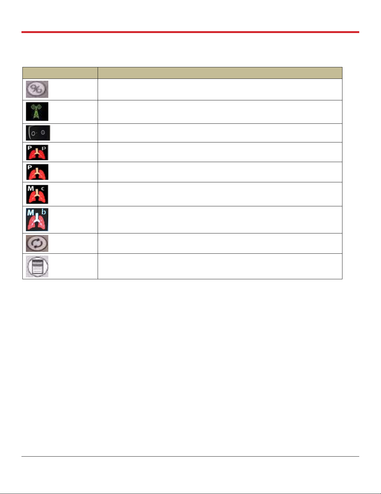
List of Symbols
Symbol
Meaning
Run/Standby button on Wireless Monitor
Wireless Bluetooth link between the Wireless Monitor and the OCS™ Lung Console
ON position for OCS™ Lung Console
Pause Preservation mode icon on the Wireless Monitor screen
Preservation mode icon on the Wireless Monitor screen
Continuous Monitoring mode icon on the Wireless Monitor screen
Bronchoscope Monitoring mode icon on the Wireless Monitor screen
Pump Adjust button on Wireless Monitor
Main configuration button on Wireless Monitor
LIST OF SYMBOLS IN THIS GUIDE
PN 100004071, Rev 5 Page 5

Glossary of Terms
Term
Meaning
ABG
Arterial Blood Gas
BPM
Breaths/minute
Bronchoscope
Mode
Ventilation of the lungs with ambient air, to allow endoscopic examination of lung’s airways
Bronchoscope
Port
Port on the Lung Perfusion Module through which a Bronchoscope probe may be inserted to inspect
the interior of the lung
Circuit
Refers to the perfusate loop in the Lung Perfusion Module
Continuous
Monitoring
Mode
The Ventilator Mode in which the OCS™ Lung System continuously deoxygenates the perfusate by
supplying Lung Monitoring Gas into the gas exchanger. At the same time, ambient air is used to
ventilate the lung. Medical professionals may evaluate the capabilities of the lungs according to their
clinical judgment by comparing the base O
2
saturation of the deoxygenated perfusate to the O2
saturation of the perfusate exiting the lung.
Cuvette
An adapter on the perfusion module used for an oxygen saturation measurement probe.
Data Card
A removable SD Data card used to store perfusion, ventilation, and monitoring parameters from the
current session, which can be downloaded and analyzed on a personal computer
FiO2
Fraction of inspired oxygen
HCT%
Hematocrit, expressed as a percentage by volume
LA
Left atrial
LGRSAE
Lung graft-related serious adverse event
L/min
Liters/minute
LPM
Lung Perfusion Module
MDI Port
Metered Dose Inhaler port on the Lung Perfusion Module through which MDI drugs may be injected
into the lungs
mL/hr
Milliliters per hour
mL/min
Milliliters per minute
mmHg
Millimeters of mercury
Mobile Base
The removable Mobile Base has four wheels, with brakes on the front wheels. The Mobile Base can
be installed as needed during system use. During transport, raise the two-position handle to push the
system. With the Mobile Base removed, you can set the system flat or carry it with the lift handles.
Organ Care
System
The Organ Care System (OCS™) houses the removable Wireless Monitor, circulatory pump driver,
multi- mode Ventilator, drive and control, batteries, data card, gas delivery subsystem, and reusable
flow and pulse oximeter probes. When in active use, it houses the disposable Lung Perfusion
Module.
PA
Pulmonary artery
PaO2
Partial pressure of oxygen in mmHg in arterial (oxygenated) perfusate.
PAP
Pulmonary Artery Pressure. The perfusate pressure in mmHg at the Pulmonary Artery cannula as the
perfusate flows into the lungs.
GLOSSARY OF TERMS
PN 100004071, Rev 5 Page 6

Glossary of Terms
Term
Meaning
Pause
Preservation
Mode
A Ventilator mode in which the bellows remain stationary and the OCS™ Lung System achieves a
static level of lung inflation. Pause Preservation enables oxygenation of perfusate prior to lung
instrumentation using the Lung Preservation Gas.
PAWP
Peak Air Way Pressure. The peak pressure in the lungs at the end of the inspiration. When the
measured PAWP reaches the user-set PAWP limit, the Ventilator will stop. PAWP corresponds to
Peak Inspiratory Pressure on mechanical Ventilators.
PEEP
Positive End Expiratory Pressure. The pressure maintained in the lungs by the Ventilator at the end of
the expiration phase
Perfusate
The fluid pumped through the lung that delivers dissolved gases and nutrients.
Power-cycle
To power-cycle the lung system, use the On/Off switch on the side of the OCS™ Lung Console to
turn the system OFF, wait 10 seconds, and then turn it ON.
Preservation
Mode
A Ventilator mode in which the OCS™ Lung System operates with the lung rebreathing the same
captive breath. A small percentage of fresh Lung Preservation Gas is injected into the ventilation
circuit to maintain the required gas concentration and to maintain Positive End Expiratory Pressure
(PEEP).
Priming Inlet
Port
Port on the Lung Perfusion Module through which priming solution and other large-volume perfusate
components flow into the reservoir
Priming Solution
The sterile OCS™ Lung Solution added to the reservoir through the priming inlet port to preserve the
lungs supplemented with other perfusate components.
Pump
Compliance
Chamber
It is located between the circulatory pump and the perfusate warmer. Its main function is to dampen
the pulsatile flow from the Pump.
Pump Flow
Probe
A probe that you attach to the Lung Perfusion Module. It is used to measure OCS™ Lung System
Pump flow.
PvO2
Partial pressure of oxygen gas in mmHg in venous (deoxygenated) perfusate.
RR
Respiration Rate. Number of respiration cycles per minute in units of breaths/minute
Run Mode
Power mode where the system is on, the Wireless Monitor is active, and the Pump and Ventilator can
operate
SaO2
Oxygen saturation of arterial (oxygenated) perfusate, expressed as a percentage and measured at
the outflow of the lung at the LA drain
SaO2/Hematocrit
Probe
An OCS™ Lung System probe that you attach to the Lung Perfusion Module. It is used to measure
the arterial oxygen saturation and the hematocrit of the perfusate leaving the lung through the LA.
Session
A session is created in internal system memory when the system is set to Run Mode. Every time Run
Mode is entered, you can choose whether to continue using the last session file or create a new one.
In ordinary circumstances, data from all procedures associated with an organ should be documented
in only one session. The system logs all system error events, all alarm events, trend data for each
parameter at 2-minute intervals, and all system operating events that occur in each session.
Standby-Cycle
To Standby-cycle the system, press the Standby button to switch from Run Mode to Standby Mode
and then back to Run Mode. The system will automatically run the Self Test.
Standby Mode
A power mode where the system is on but the Wireless Monitor is off and no ventilation or perfusion
may be performed. Standby Mode is the mode used during OCS™ Lung System storage; organs
cannot be preserved in this mode. The OCS™ must be plugged in to AC power to avoid battery
depletion when storing the lung system in this mode.
PN 100004071, Rev 5 Page 7

Glossary of Terms
Term
Meaning
SvO2
Oxygen saturation of venous (deoxygenated) perfusate, expressed as a percentage and measured at
the inflow to the lung on the PA line
SvO2/Hematocrit
Probe
An OCS™ Lung System probe that you attach to the Lung Perfusion Module. It is used to measure
the venous oxygen saturation and hematocrit of the perfusate entering the lung through the
pulmonary artery cannula.
Temp
Temperature of perfusate supplied to the lung, displayed on the Wireless Monitor in degrees Celsius
TV
Tidal Volume. The volume of air breathed in and out of the lungs during a respiration cycle.
VR
Vascular Resistance. This is a measure of the resistance to flow that must be overcome to push
perfusate through the vasculature of the lungs. It is calculated as (80* mean PAP)/(Pump Flow) and
displayed in units of (dyne*sec)/cm
5
.
Waveform
Real-time waveforms display continuously updated data. The waveforms are drawn from left to right
with the most current data. An update bar displays the oldest data first. If more than one graphic
frame is configured to show real-time waveforms, the update bars are automatically synchronized.
The airway pressure waveform is always displayed in the top-most frame on the Wireless Monitor.
Use the Configuration Menu to configure which of the following waveforms are displayed in the
middle and bottom frames on the Wireless Monitor.
Wireless Monitor
A small, dockable monitoring system with an LCD screen and controls for configuring system
functions and screen displays, and for adjusting system settings during preservation. When removed
from its docking station on the OCS™ Lung Console, the Wireless Monitor operates wirelessly,
powered by its own battery.
PN 100004071, Rev 5 Page 8

Chapter 1: Read this First
1. CHAPTER 1: READ THIS FIRST
This chapter contains important information about the documentation for your TransMedics® Organ
Care System (OCS™) and about contacting TransMedics.
1.1. Directions to User
This manual provides detailed instructions regarding clinical use of the OCS™ Lung System. For a
system overview, how to set up the system, and understanding the Wireless Monitor controls and
functions, see the TransMedics Technical User Guide: OCS™ Lung System. Both guides are to be
reviewed prior to using the system, noting the Warnings and Cautions throughout the guides.
The OCS™ Lung System can only be purchased upon order of a physician. A TransMedics
representative must install and activate each newly purchased system before a qualified health care
professional can use it.
1.2. User Training Requirements
The OCS™ Lung System enables medical professionals to monitor key parameters that may be
useful in assessing organ condition and function according to their clinical judgment. The system is
intended for use only by qualified healthcare professionals specializing in lung transplants and
trained in the use of the OCS™ Lung System.
Completion of the TransMedics training program is required for every new lung transplant center
prior to starting an OCS™ Lung System program at their institution. All team members who will be
using the OCS™ Lung System at an institution must be trained. The training consists of initial handson training and periodic refresher training as needed.
1.3. Patient Counseling
The patient should be instructed to review the Patient Brochure and discuss the warnings,
precautions, and complications. At the end of the Patient Brochure, there is a patient decision
checklist for the patient’s review and signature.
1.4. Indications for Use
The TransMedics® Organ Care System (OCS™) Lung System is a portable organ perfusion,
ventilation, and monitoring medical device indicated for the preservation of standard criteria donor
lungs in a near physiologic, ventilated, and perfused state for double lung transplantation.
1.5. Contraindications
Moderate to severe traumatic donor lung injury with air leak (as seen on radiological studies,
bronchial examination or final visual assessment in donor’s chest) to avoid:
• Perfusate leakage from injury site into the airways and potential edema formation
• Inability to recruit donor lungs due to air leak.
PN 100004071, Rev 5 Page 9

Chapter 1: Read this First
WARNING—Safety and effectiveness of the OCS™ Lung System for marginal/extended criteria
lungs, including donor lungs subjected to extended preservation times, have not been studied in the
1.6. Warnings and Precautions
WARNING— Only trained users are allowed to use the OCS™ Lung System.
PRECAUTIONS— The safety and effectiveness of the OCS™ Lung System has not been studied in
recipients with the following:
• Single lung transplant
• Prior solid organ or bone marrow transplant
• Multi-organ transplants
• Chronic use of hemodialysis or diagnosis of chronic renal failure requiring dialysis.
Safety and effectiveness of the OCS™ Lung System has not been studied for donor organs with
Hepatitis B and Hepatitis C.
A device malfunction or user error could lead to a potential loss of a donor organ.
1.7. Conventions
The system, OCS™ Lung System, the lung system, and OCS™ are used interchangeably throughout
this manual to refer to the TransMedics OCS™ Lung System.
The system uses consistent conventions throughout the interface and accompanying documentation
to make it easy for you to learn and use.
WARNING—A Warning alerts you to a potential serious outcome, adverse event or safety
hazard. Failure to observe a warning may result in loss of organ, death, or serious injury.
CAUTION—A Caution alerts you to situations where special care is necessary for the safe and
effective use of the product. Failure to observe a caution may result in minor or moderate personal
injury or damage to the product or other property, and possibly a risk of more serious injury.
NOTE—A Note brings your attention to important information that will help you operate the system
more effectively.
PN 100004071, Rev 5 Page 10

Chapter 1: Read this First
1.8. Supplies
The components, accessories, and supplies required when using the OCS™ Lung System must be
used in accordance with this user manual, associated documents, and accepted medical standards.
CAUTION—Only accessories and supplies purchased from or recommended by TransMedics, Inc. are to be used
with the TransMedics OCS™ Lung System. Use of accessories and supplies other than those supplied by or
recommended by TransMedics may cause system malfunction and invalidate the TransMedics warranty.
For details on what is included with your OCS™ Lung System, see the TransMedics Technical User
Guide: OCS™ Lung System.
To order additional parts and supplies, see Section 10 of the TransMedics Technical User Guide:
OCS™ Lung System. Other materials, not supplied by TransMedics, are required to operate the
OCS™ Lung System. See Section 3.
1.9. Contacting TransMedics
1—For Customer Clinical Support:
Please contact TransMedics prior to departure to donor site on one of the following numbers:
US/AUS/Canada: +1 978-222-3733
EUR: +31(0) 20-7084561
2—For Customer Service:
Please contact TransMedics at Tel: +1 978-552-0999
You can also contact one of the following offices for referral to a customer service representative, or
visit the TransMedics website: www.transmedics.com.
Corporate and North American Headquarters
TransMedics, Inc.
200 Minuteman Road, Suite 302
Andover, MA 01810, USA
Tel: +1 978-552-0999
Fax: +1 978-552-0978
Authorized EU Representative
Healthlink Europe
De Tweeling 20-22
5215 MC’s Hertogenbosch
The Netherlands
Telephone: +31(0) 13 547 9316
PN 100004071, Rev 5 Page 11
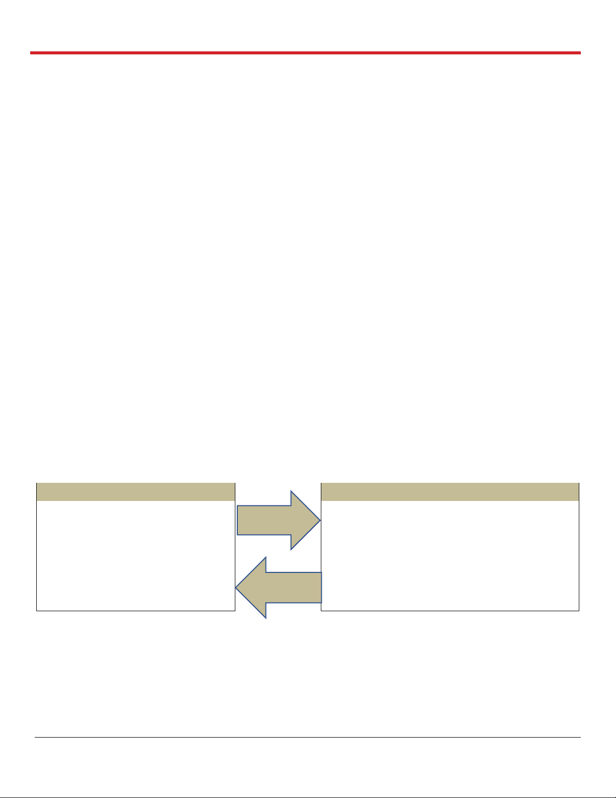
Chapter 2: Overview of OCS™ Lung System
Recipient Site
Donor Site
• OCS™ Lung System Procedure
Checklists
• Optional: Install the LPM, System
passes Self Test
• Final Continuous & Bronchoscope
Monitoring Modes
• Final lung flush and implantation
• Install the LPM (if not done at Recipient site)
• Prime the LPM
• Harvest the lungs
• Instrument lungs on OCS™ Lung System
• Perfusion and Ventilation
• Baseline Continuous Monitoring Mode
• Preservation Mode
Travel to
Donor Site
Preservation
& Transport
2. CHAPTER 2: OVERVIEW OF OCS™ LUNG SYSTEM
The TransMedics® Organ Care System (OCS™) Lung System is a portable organ perfusion,
ventilation and monitoring medical device intended to preserve donated lungs in a near physiologic,
ventilated, and perfused state for transplantation. The OCS™ Lung System enables medical
professionals to continuously monitor key parameters that may be useful in assessing organ
condition and function according to their clinical judgment.
2.1. System Components
The system consists of the following major components:
1. Lung Console: The Lung Console is a non-sterile, reusable, portable enclosure that houses
an electronic display and non-sterile mechanical and electrical elements required to warm,
pump, ventilate, and manage gas content of the perfusate.
2. Lung Perfusion Set: The Lung Perfusion Set (LPS) includes a sterile, single-use perfusion
module (Lung Perfusion Module or LPM) and various accessories. The perfusion module
consists of an organ chamber and a circulatory system to perfuse and ventilate the lung. The
supplied accessories connect the lung to the organ chamber and facilitate the management
of fluids within the perfusion module.
3. OCS™ Lung Solution: This is the high oncotic solution used for ex-vivo flush and perfusion of
donor lungs when combined with pRBCs.
2.2. Overview of OCS™ Lung System Preservation Process
Figure 2.1 illustrates the various activities performed at the donor site during preservation and at the
recipient hospital.
Figure 2.1: OCS™ Lung System Preservation Process Overview
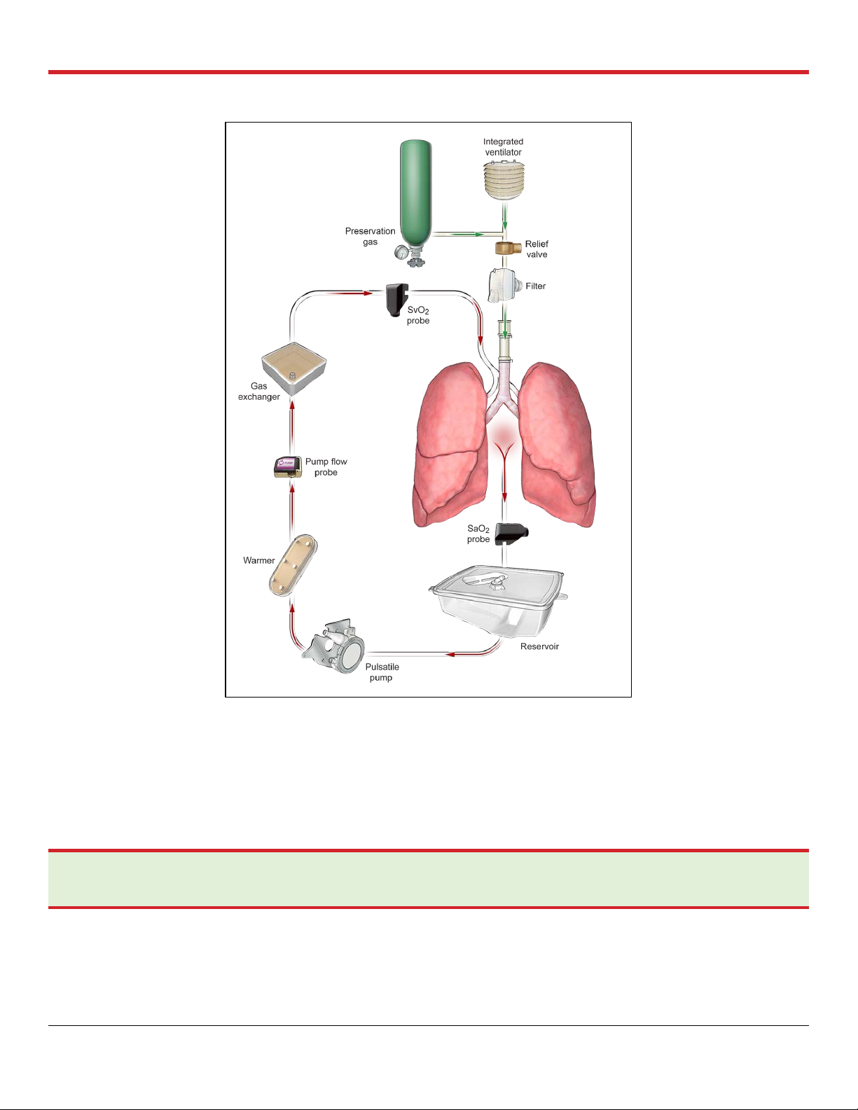
2.3. Overview of Perfusion and Ventilation
The OCS™ Lung System preserves ventilated lungs using warm oxygenated cellular perfusate. The
system supports several Ventilator modes to ensure both preservation and assessment of lung
function during retrieval. Ventilator modes of the lung system include the following: Pause
Preservation; Preservation; Continuous Monitoring; Bronchoscope Monitoring; and OFF Mode.
Figure 2.2 shows an overview of the circulation and ventilation.
PN 100004071, Rev 5 Page 12
Chapter 2: Overview of OCS™ Lung System
Figure 2.2: Circulation and Ventilation Overview
2.4. Clinical Study of the OCS™ Lung System
The safety and effectiveness of the OCS™ Lung System was studied in a large randomized,
controlled, multi-center study. A summary of the study and the results are provided in Appendix A of
this document.
NOTE—It is essential that you carefully review the study results in Appendix A: OCS
you have any questions about these results, please contact TransMedics.
PN 100004071, Rev 5 Page 13
™
Lung System INSPIRE Study. If

Chapter 3: Activities Performed Before Departure to Donor Site
3. CHAPTER 3: ACTIVITIES PERFORMED BEFORE DEPARTURE TO
DONOR SITE
Adequate preparation ensures the smoothest possible organ retrieval run with the OCS™ Lung
System. This chapter provides information on the checklists and tasks that are performed at the
recipient site prior departure to the donor site.
3.1. Procedure Overview Checklist
3.1.1. General Checklist
1. OCS™ Lung Console, removable cover, and 3 fully charged OCS™ Lung System batteries.
2. Lung Preservation Gas cylinder (>30% full) and Lung Monitoring Gas cylinder (>50% full). For
less gas, replace, or take a spare cylinder.
3. 2 L of OCS™ Lung Solution, medications, and additives needed for priming. Refer to Section
3.3.
4. OCS™ Lung Solution for donor lung flush with buffering additives.
5. 3 units of leukocyte reduced packed red blood cells (pRBCs) – ABO type-
matched/compatible to transplant recipient.
6. OCS™ Lung Perfusion Module (LPM) and Accessory Sets
a. OCS™ Lung Instrumentation Tool Set
b. OCS™ Lung Perfusion Initiation Set
c. OCS™ Lung Perfusion Termination Set.
7. OCS™ Run Bag and contents.
3.1.2. OCS™ Lung Console Checklist
1. Ensure the OCS™ Lung System passes Self Test and is set to Run Mode.
2. With the OCS™ Wireless Monitor correctly docked on the lung system and in Standby mode,
press the button on the Monitor to set the OCS™ Lung System to Run Mode.
3. Ensure Bluetooth is enabled on the Wireless Monitor .
4. Check the date and time, and adjust as needed.
5. The OCS™ Lung Preservation Gas cylinder is installed properly inside the gas compartment.
Open the cylinder to check the status of the Lung Preservation Gas on the Wireless Monitor.
6. Check the status of the 3 fully charged OCS™ Lung System batteries as follows:
a. Press the test button (located on the front of each battery) to check battery charge.
b. Battery status will be displayed on the Wireless Monitor once the Lung System is set to
Run Mode.
PN 100004071, Rev 5 Page 14

Chapter 3: Activities Performed Before Departure to Donor Site
c. For detailed instructions on checking the battery status and charging the batteries, see the
TransMedics Technical User Guide: OCS™ Lung System.
NOTE—Each fully charged battery provides a minimum of 80 minutes of power, totaling four hours of power
with three fully charged batteries under normal operating conditions. Additional batteries can be ordered from
TransMedics® as needed.
7. The OCS™ Lung System has a TransMedics approved Data Card.
8. After OCS™ Lung Console check, switch back to Standby Mode by pressing on the
Wireless Monitor until the LPM is installed.
3.2. Checklists for OCS™ Lung Gas Cylinders
3.2.1. Lung Preservation Gas Cylinder
The Lung Preservation Gas is composed of 12% Oxygen, 5.5 % CO
and 82.5 % Nitrogen balance.
2,
The Lung Preservation Gas is used by the system during Priming in the Pause Preservation Mode to
oxygenate the perfusate, as well as throughout transportation to ventilate the lungs in the
Preservation Mode. The Lung Preservation Gas cylinder needs to be installed inside the gas
compartment of the OCS™ Lung Console before using the system.
A full Lung Preservation Gas cylinder contains 3000 psi.
Lung Preservation Gas Cylinder checklist:
1. Ensure the Lung Preservation Gas cylinder is ≥ 30% full (at least 900 psi); otherwise, replace
or take a spare full cylinder and store in the Run Bag.
• Open the Lung Preservation Gas cylinder valve with the gas cylinder wrench, located in
the front of the gas compartment, and check the level on the gas gauge. To open the
valve, turn it in counter-clockwise direction.
• The Lung Preservation Gas level will be reflected, as well on the gas status icon, on the
Wireless Monitor screen after opening the cylinder’s valve and switching the Lung System
to Run Mode.
2. Close the cylinder’s valve (turn in clockwise direction) after check and until priming the LPM
at the donor’s site.
NOTE—For more information, see “Estimating the Remaining Preservation Gas Supply” in the TransMedics Technical
User Guide: OCS™ Lung System. Replace the cylinder if necessary. Close the gas valve after check and after use.
3.2.2. Lung Monitoring Gas Cylinder
The Lung Monitoring Gas is composed of 6% CO2 and 94% Nitrogen balance. Lung Monitoring Gas
is needed to assess oxygenation capacity of lungs preserved on the OCS™ Lung System in
Continuous Monitoring Mode. To use the Lung Monitoring Gas, the cylinder needs to be connected
to the lung system using the Monitoring Gas Regulator Kit.
A full Lung Monitoring Gas Cylinder contains 3000 psi.
PN 100004071, Rev 5 Page 15
Chapter 3: Activities Performed Before Departure to Donor Site
Lung Monitoring Gas Cylinder checklist:
1. Ensure the Lung Monitoring cylinder is ≥ 50% full (At least 1500 psi) before departure to
donor site. Otherwise, replace or take a spare.
2. Regulator and green line (Monitoring Regulator Kit) are attached to the cylinder before usage.
3. Connect the Lung Monitoring cylinder to the Monitoring port on the OCS™ Lung Console and
open its valve by turning it in counterclockwise position. Check the gauge reading on the
Regulator Kit.
4. Close the Monitoring Gas cylinder’s valve (turn in clockwise direction) and store the cylinder
in the retrieval Run Bag.
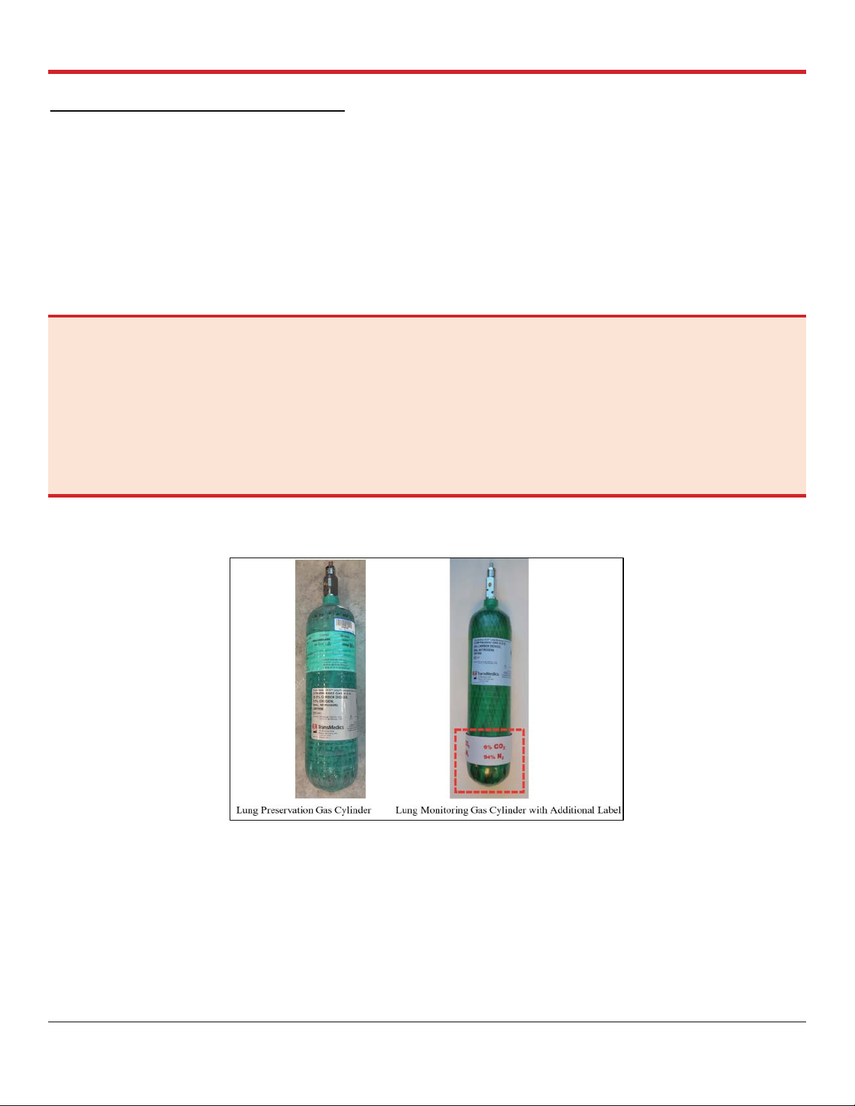
WARNINGS—
Please note the different colors of the labels on the Lung Monitoring and the Lung Preservation Gas cylinders, to ensure
installing the correct cylinder inside the OCS™ Lung Console.
To avoid the inadvertent insertion of the Lung Monitoring Gas cylinder into the OCS™ Lung Console, an additional label is
placed around the Lung Monitoring Gas Cylinder to prevent it from fitting into the Lung Console’s Preservation Gas
compartment.
NO attempts should be taken to remove this additional label at any time. See Figure 3.1.
Figure 3.1: Lung Monitoring Cylinder with Additional Differentiating Labels from Lung Preservation
Cylinder
3.3. OCS™ Lung Solution & Additives Checklists
3.3.1. Donor Lung Flush
• Use at least 3-5 L of cold buffered* OCS™ Lung Solution for antegrade flush
supplemented with 50 mg of nitroglycerin in the first flush bag.
• Use at least 1-2 L of cold buffered* OCS™ Lung Solution for retrograde flush.
• Deliver flush by gravity.
PN 100004071, Rev 5 Page 16
Chapter 3: Activities Performed Before Departure to Donor Site
Component
Concentration (g/L)
Dextran 40
50
Glucose Monohydrate
2
Magnesium Sulfate Heptahydrate
.201
Potassium Chloride
0.4
Sodium Chloride
8
Dibasic Sodium Phosphate Dihydrate
0.058
Monopotassium Phosphate
0.063
Water for Injection To 1000 mL
Hydrochloric Acid pH adjustment
Medication
Dose
Multivitamins
1 unit
Methylprednisolone
500 mg
Insulin
20 IU
Milrinone (Primacor®)
4 mg
NaHCO3
40 mEq
*Use 10 mEq of NaHCO3 or 1 mmol of THAM/L (tromethamine) to buffer the OCSTM Lung
Solution immediately before usage.
3.3.2. OCS™ Lung Perfusate & Additives
• 1.5-2 L of buffered* OCS™ Lung Solution is the only recommended solution for priming
the LPM in preparation for Lung perfusion on the OCSTM Lung System
* Use 10 mEq of NaHCO3 or 1 mmol of THAM/L to buffer the OCSTM Lung Solution
immediately before usage.
• 3 units of leukocyte reduced, CMV negative, ABO-typed/compatible pRBCs to the
transplant recipient ABO type
Table 3.1: OCS™ Lung Solution Composition
CAUTION—The OCS™ Lung Solution is ONLY intended for use with the OCS™ Lung System. The OCS™ Lung
Solution is NOT intended for intravenous injection.
Table 3.2: Perfusate Additives (added once at time of Priming)
PN 100004071, Rev 5 Page 17

Chapter 3: Activities Performed Before Departure to Donor Site
Medication
Dose
Cefazolin (or equivalent gram positive antibiotics in prophylactic
dose)
1 g
Ciprofloxacin (or equivalent gram negative antibiotics in
prophylactic dose)
200 mg
Voriconazole (or equivalent antimycotic in prophylactic dose) e.g.,
Caspofungin
200 mg
(or 70 mg of Caspofungin)
Table 3.3: Perfusate Prophylactic Medications (added once at time of Priming)
3.3.3. Perfusate Corrective Medications Checklist– (As needed & after every blood sample
check)
1. NaHCO3 for low bicarbonate (< 22 mmol/L)
2. Dextrose for low glucose (< 120 mg/dL)
3. Nitroglycerin for high pulmonary artery pressure (PAP) (Mean PAP >20 mmHg)
3.4. Leukocyte Reduced Packed Red Blood Cells (pRBCs) Checklist
1. 3 units are required to use with the OCS™ Lung System
2. ABO compatible (to transplant recipient)
3. Tested Cytomegalo Virus (CMV) Negative
4. Leukocyte reduced
5. Stored in a cooler during transport
3.5. OCS™ Lung Perfusion Set Checklists
1. Check the expiration date and check for any obvious shipping damage on the Lung Perfusion
Set (LPS).
2. If the date has expired or if any damage is found to a packaged LPS, do not use this LPS.
3. Installing the Lung Perfusion Module (LPM) prior departure to donor site is optional. For
details of installing the LPM, refer to Section 4.
4. If the LPM is installed before departure to donor site, Accessory Sets shipped with the
corresponding LPS should be stored in the OCS™ Run Bag to be used at the donor site.
5. Accessory Set packages should not be opened until just before use at the donor site.
6. Once the LPM is installed, switch the OCS™ Lung System to Run Mode and verify that the
lung system passes the Self Test.
a. If displayed errors indicate problems, refer to the Troubleshooting chapter in the
TransMedics Technical User Guide: OCS™ Lung System.
7. If no errors display, select “New Session File” and confirm the following:
a. Ventilator Mode is defaulted to Pause Preservation
PN 100004071, Rev 5 Page 18

Chapter 3: Activities Performed Before Departure to Donor Site
b. NO (+++) OR (- - -) values are displayed on the Monitor for Pulmonary Artery Pressure
(PAP) or the airway pressure readings.
WARNING—Abnormal values of either (+++) or (- - -) displayed on the Wireless Monitor as Mean PAP or if
airway pressure measurements indicate readings above or below (respectively) preset ranges as read by the
sensors in the installed LPM. If this abnormality is detected, DO NOT use the installed Module, and replace it
with a new one to ensure proper management of perfusion and ventilation parameters during lung preservation.
8. Switch back to Standby Mode until the module is ready for Priming at the donor site.
WARNING—Without a Sterile OCS
be used.
™
Lung Perfusion Set (LPM and Accessory Sets), the OCS® Lung System cannot
3.6. Run Bag Checklist and Contents
1. 2 L of OCS™ Lung Solution with buffering agents (THAM/NaHCO3) for LPM priming at donor
site
2. Perfusate additives and medications (prophylactic and corrective) listed in Section 3.3.
3. OCS™ Lung Monitoring Gas cylinder (≥ 50% full) & Monitoring Gas Regulator Kit
4. Sterile syringes, needles, gloves, alcohol wipes and petroleum jelly/Vaseline®
5. OCS™ Lung Accessory Sets (if the LPM is installed before departure to donor site):
a. OCS™ Lung Instrumentation Tool Set
b. OCS™ Lung Perfusion Initiation Set
c. OCS™ Lung Perfusion Termination Set
6. A sterile OCS™ Lung Manual Inflation Set/Ambu Bag
7. Spare gas wrench and tie-downs to secure the OCS™ Lung Console during transport
NOTE—When transporting the system prior to and during a preservation session, if necessary, bring along extra
charged batteries, extra gas cylinder(s), and country-specific power cords as required.
3.7. Transport Considerations
When selecting a transport vehicle, consider the following:
1. Identify a level area large enough to accommodate the OCS™ Lung Console (with its mobile
base removed), approximately 29” x 19” x 29” (72 cm x 46 cm x 72 cm).
2. Position the OCS™ Lung System for access to its gas and batteries, if possible.
3. Secure the OCS™ Lung Console to the vehicle to immobilize it during transport, using tiedowns.
4. Install the OCS™ Lung Console cover to avoid heat loss (particularly returning to the recipient
site).
5. Ensure the ambient temperature of the OCS™ in the vehicle is consistent with normal
passenger comfort, e.g. 20°C.
PN 100004071, Rev 5 Page 19
Chapter 3: Activities Performed Before Departure to Donor Site
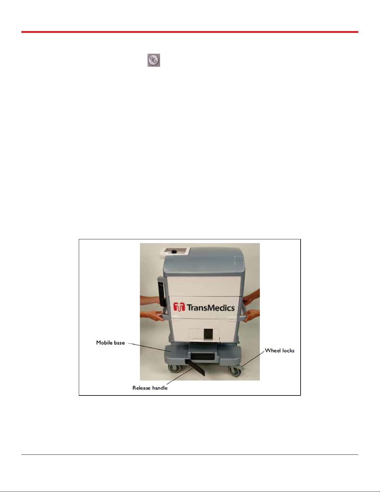
3.7.1. Preparing the OCS™ Lung System for Travel to Donor Site
1. Press the Run/Standby button on the docked Monitor to set the lung system back to
Standby Mode.
2. Unplug the OCS™ Lung Console from the AC receptacle and wind the power cord around the
power cord wrap.
3. With the Mobile Base installed, press the push handle release buttons, raise the handle and
push the Lung Console to the loading area.
4. Lock the Mobile Base wheels by pressing each wheel break down.
5. Disconnect the Mobile Base from the OCS™ Lung Console by pulling the release handle
outwards to release the Mobile base grips.
6. With two people using the right and left lift handles, lift the OCS™ Lung System into the
transport vehicle.
7. Position the OCS™ Lung Console level in the vehicle and secure it using tie-downs.
8. Remember to take the Mobile Base with you for use at the donor site.
For additional information on safely transporting the OCS™ Lung System, including temperature and
humidity limits, see the TransMedics Technical User Guide: OCS™ Lung System.
Figure 3.2: Lifting the OCS™ Lung Console off the Mobile Base
PN 100004071, Rev 5 Page 20

Chapter 4: Activities Performed at Donor Site
4. CHAPTER 4: ACTIVITIES PERFORMED AT DONOR SITE
This chapter provides instructions for the tasks that are performed at the donor site to retrieve,
preserve, monitor and assess the lungs’ function throughout transport.
NOTE—The LPM may be installed in the OCS™ Lung System before going to the donor site. At the donor site, allow at
least 30 minutes to prepare medications and prime the LPM with the perfusate before the lungs are instrumented on the
lung system.
CAUTION—Keep the OCS
continuously charging its batteries.
TM
Lung System connected to a live AC power at all times when available to ensure
4.1. Unpacking, Installation, and OCS™ Lung System Setup
This section provides instructions for unpacking the Lung Perfusion Set, installing the LPM,
attaching the probes, and running the system Self Test.
4.1.1. Unpacking and Inspecting the Lung Perfusion Set (LPS)
Accessories packaged and shipped with the LPS should be unpacked immediately before use.
For illustrations and descriptions of the components included in the LPS, see the TransMedics
Technical User Guide: OCS™ Lung System.
4.1.2. Unpacking and Inspecting the Sterile Components
1. Inspect the packaging of each sterilized component for tears or breaks in the seal that might
compromise sterility. If any tears or damage are found, do not use the damaged item.
CAUTION—Check the expiration date on each package. If the date has expired, do not use the item.
2. Unpack each sterilized component immediately before use.
3. Open the Lung Instrumentation Tool Set components in a sterile field, using a sterile
technique.
4.1.3. Opening the LPM Packaging
1. Check the expiration date and inspect for any obvious shipping damage. If the date has
expired or if any damage is found, do not use the LPM.
2. Partially lift the bagged LPM out of the box, supporting the bottom of the module on the foam
insert.
3. Open the bag by locating the blue notch at the bag’s corner and tearing straight across until
you reach the other notched corner.
4. Carefully remove the LPM from the bag and discard the bag.
PN 100004071, Rev 5 Page 21
Chapter 4: Activities Performed at Donor Site
5. Supporting the bottom of the LPM on the foam insert inside the box, grasp the corner of the
foam wrapped around the LPM and tear off the foam.
6. Remove the foam block from the rear of the LPM.
7. After removing the LPM from its box, regardless of whether the module is still in its sterile bag
or not, lay the LPM on its right side and on a flat surface. Laying the LPM on its back or front
may damage it.
WARNING—Inspect the bellows plate prior installing the LPM. If it is disengaged from all or some of the holding
clips, refer to the Troubleshooting chapter of the TransMedics Technical User Guide: OCS™ Lung System before
installing the module in the OCS™ Lung Console.
4.2. Installing the LPM on the OCS™ Lung System
For photos of the back and front of the LPM and its location inside the OCS™ Lung System, see the
TransMedics Technical User Guide: OCS™ Lung System.
1. Stabilize the OCS™ Lung Console by pressing the wheel brakes on the mobile base down.
2. Remove the OCS™ Lung Console cover and lower the front panel of the system.
3. Keep the system in STANDBY mode to ensure full retraction of the Ventilator’s Actuator (arm)
and thus facilitates installing and engaging the module to the OCS™ Lung Console.
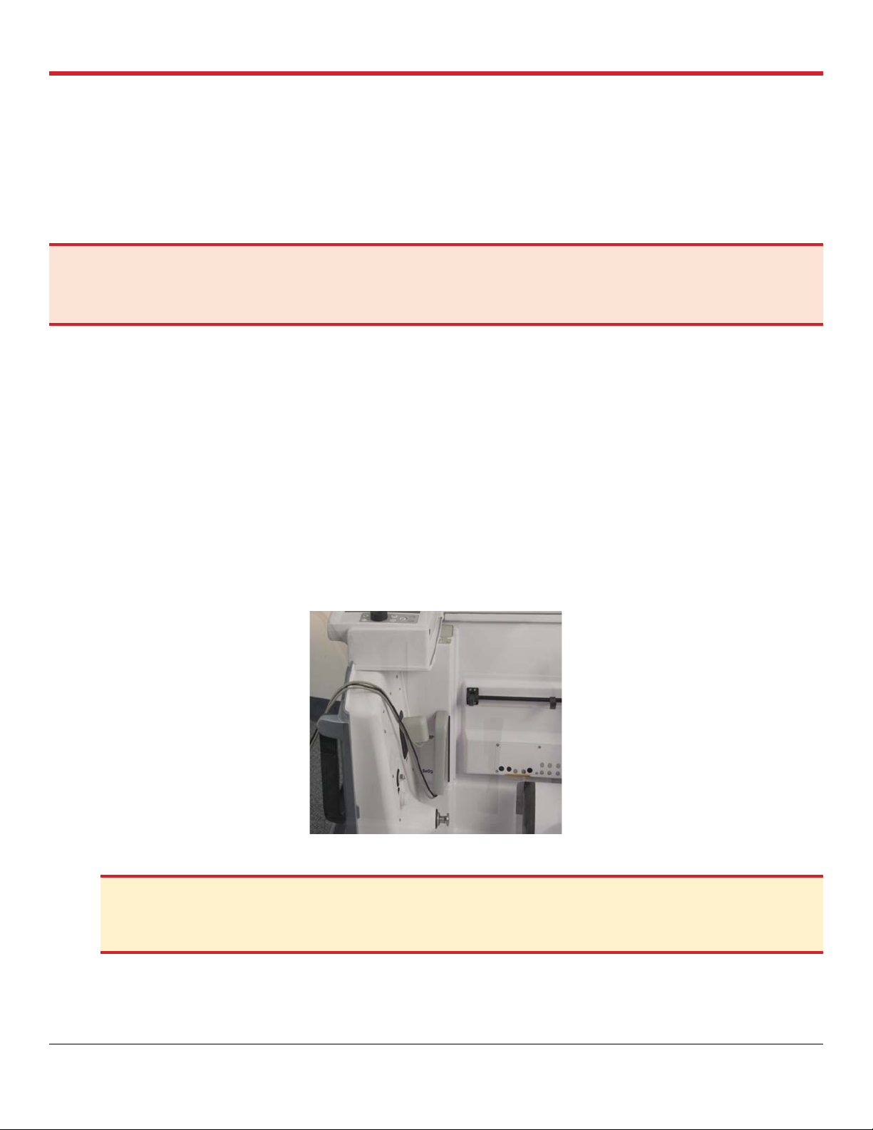
4. Pull the saturation and flow probes cables to the left to avoid getting them in the user’s way
while engaging the module to the Ventilator’s arm. See Figure 4.1.
Figure 4.1: OCS™ Lung System Probes Pulled to the Side of the LPM
CAUTION—Do not uninstall the LPM while the Pump or Ventilator is ON as doing so may cause the Pump or
Ventilator to jam. If this occurs, reset the system as described in the TransMedics Technical User Guide: OCS™
Lung System.
5. Hold the LPM from the front and back holding grips and tilt the module for 30 degrees to align
Pump head and Ventilator Actuator in the OCS™ Lung Console to engage with the Pump
dome interface and the Bellows plate hook of the module respectively. See Figure 4.2.
PN 100004071, Rev 5 Page 22

Chapter 4: Activities Performed at Donor Site
Figure 4.2: Pump Head, Ventilator Actuator of the OCS™ Lung Console (A) and the Bellows Plate of
the LPM (B)
6. Push the LPM backwards after ensuring proper alignment of the OCS™ Lung System holding
clips with the LPM’s recesses to keep it in place. See Figure 4.3. Press the release metal
handle of the OCS™ Lung Console DOWN to ensure the LPM is well seated and held by the
holding clips.
NOTE—If a resistance is faced or misalignment is detected need during installation of the LPM with the OCS
Lung Console, DO NOT proceed to avoid damaging the LPM. Disconnect the LPM by pushing the release
handle up and start all over again with Steps 5 and 6.
Figure 4.3: Holding Clips Engaging with the LPM (A) and Ventilator Actuator Engaged with the
Bellows Plate of the LPM (B)
7. Confirm proper engagement of the Ventilator Actuator with the hook on the Bellows plate as
seen in Figure 4.3B above.
™
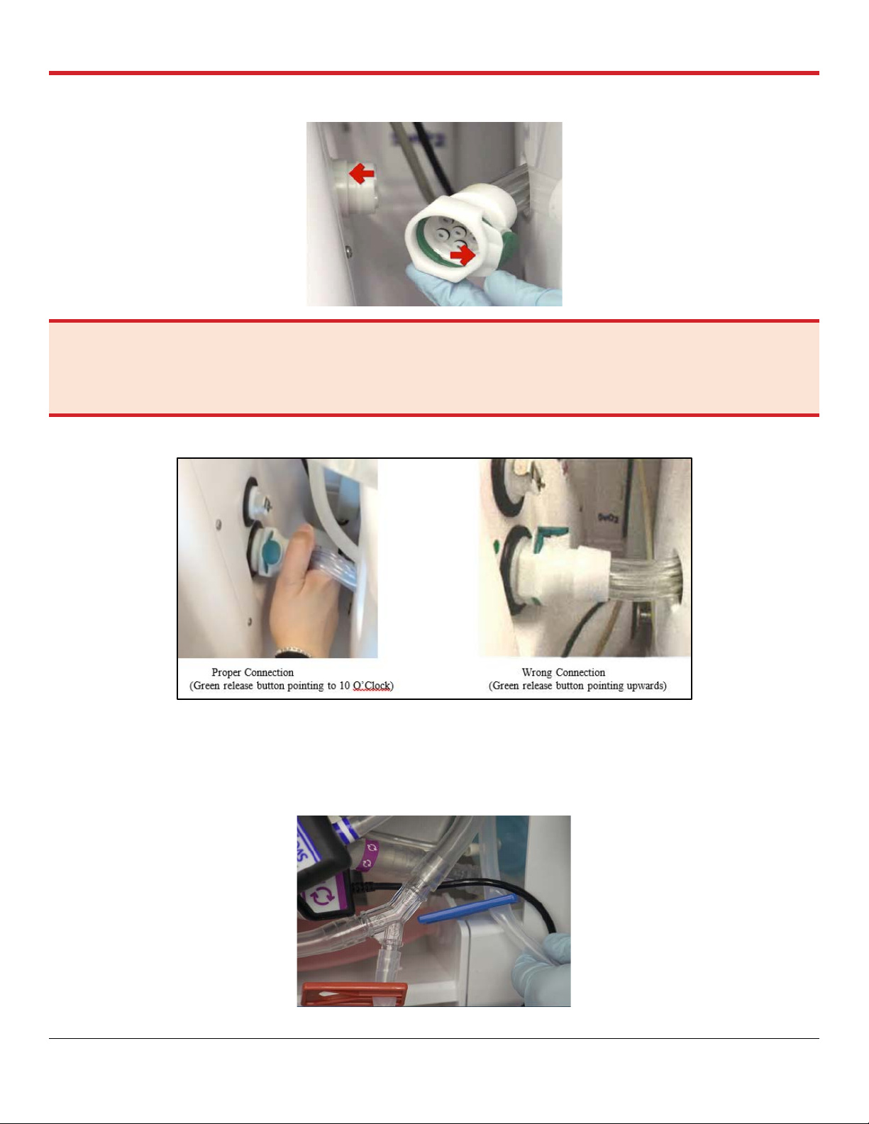
8. Hold the Ventilator lines connector of the LPM and align its inner recessed notch with the
raised tab on the Ventilator lines connection port on the OCS™ Lung Console. Once aligned,
avoid pressing the green release button on the connector while pushing it to the port until a
click is heard, which indicates a proper and secured connection. See Figure 4.4.
PN 100004071, Rev 5 Page 23
Chapter 4: Activities Performed at Donor Site
Figure 4.4: Ventilator Lines Connection Port
WARNING—When connecting the Ventilator lines, ensure that the recessed notch on the LPM Ventilator lines
connector aligns with the corresponding raised tab on the OCS™ Lung Console Ventilator lines connection port in the
Lung Console (Figure 4.4). Malconnected Ventilator lines to the connection port should be avoided to ensure proper
operation of all different Ventilator Modes (Figure 4.5).
Figure 4.5: Proper Connection vs. Wrong Correction of Ventilator Lines
9. Expose the Oxygenator recirculation line of the module and release its clamps to be opened.
Push the blue and the red clamps all the way up on the recirculation line and store in clamped
on position. See Figure 4.6.
Figure 4.6: Clamp onto the Oxygenator Recirculation Line
PN 100004071, Rev 5 Page 24
Chapter 4: Activities Performed at Donor Site
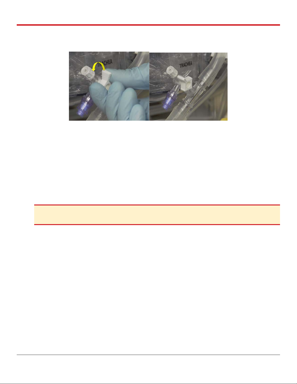
10. Close the pulmonary artery flush port as seen in Figure 4.7.
Figure 4.7: Closing the PA Flush Port
4.3. Attaching the Probes
This section provides detailed instructions on attaching the Pump flow probe, the SaO2/Hematocrit
probe, and the SvO2/Hematocrit sensor/probe to the tubing on the LPM.
4.3.1. Attaching the Pump Flow Probe
The Pump flow probe is installed between the purple bands (between the perfusate warmer and the
gas exchanger).
1. Apply a small amount of petroleum jelly to the inside of the probe.
2. Locate the color-coded bands on the LPM that match the color of the probe label.
CAUTION—Apply ONLY petroleum jelly/Vaseline
gel, such as silicone grease or ultrasound gel, may damage the Pump flow probe.
®
to the inside of the flow probe. Using any other coupling
3. Align the probe between the bands so that the double lines on the probe label are next to the
band with double lines on the tubing (Figure 4.8).
4. Insert the tubing into the sensing cavity and close the lid.
5. Make sure the lid is completely closed and the latch is secure. The fit should be tight, with the
full tubing cross-section contacting all inner surfaces of the sensing window. The tubing will
be slightly compressed into a rectangular shape.
6. Once fluid is flowing through the tubing during priming, check the Wireless Monitor display to
make sure that the desired flow parameters are being displayed.
PN 100004071, Rev 5 Page 25
Chapter 4: Activities Performed at Donor Site
Figure 4.8: Pump Flow Position
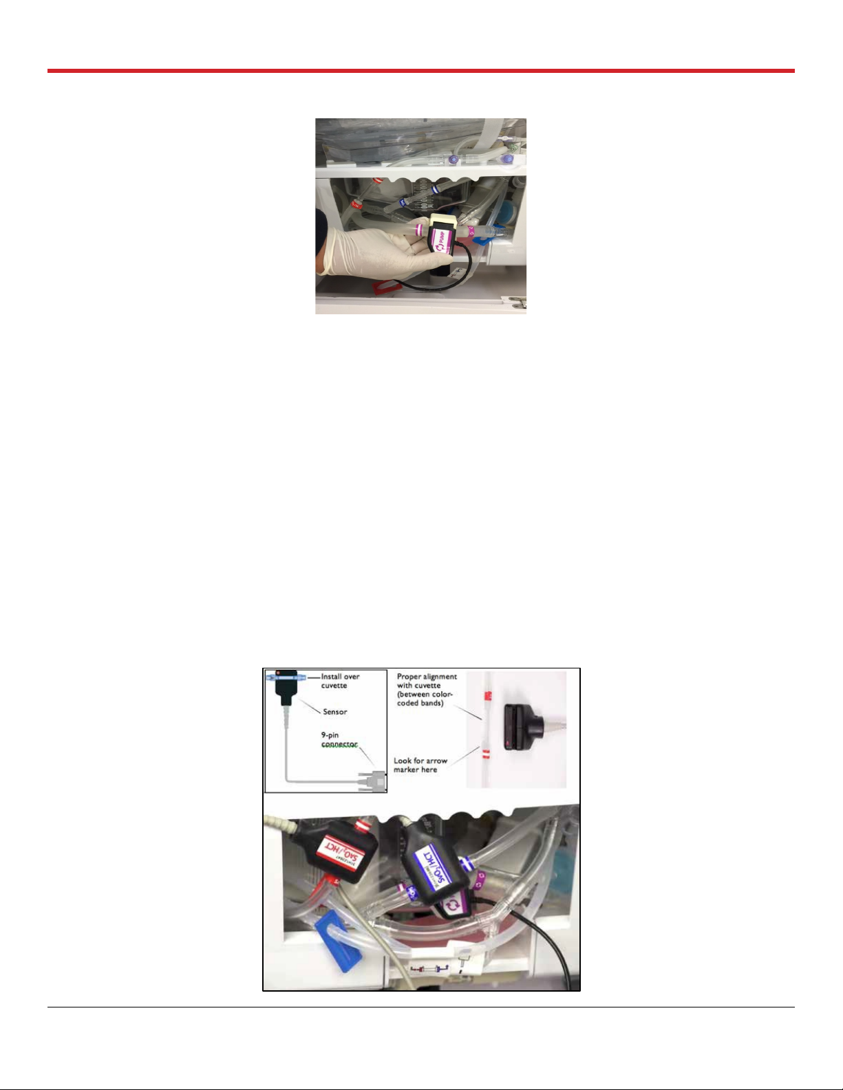
4.3.2. Attaching the SaO2/Hematocrit and SvO2/Hematocrit Probes
The SaO2/Hematocrit and SvO2/Hematocrit optical probes are designed to be clipped onto cuvettes
that are incorporated into the LPM’s tubing. The cuvette is marked with colored bands at each end.
The color of the bands should match the color of the label on the corresponding probe. Align the
probe between the bands so that the double lines on the probe label are next to the band with
double lines on the tubing.
The probes are attached to the following locations:
1. Clip the SvO2/Hematocrit probe to the cuvette between the blue bands on the line between
the gas exchanger and the pulmonary artery (PA) inflow.
2. Clip the SaO2/Hematocrit probe to the cuvette between the red bands between the left atrial
(LA) drain and the reservoir.
Figure 4.9 shows the SvO2/Hematocrit and SaO2/Hematocrit probe components and the probes
attached to the tubing.
Figure 4.9: SaO2/HCT and SvO2/HCT Probes
PN 100004071, Rev 5 Page 26
Chapter 4: Activities Performed at Donor Site
CAUTION—Ensure the saturation probes are securely connected to the cuvette.
4.4. Running the OCS™ Lung System Self Test
After the LPM is fully installed, run the system Self Test again to make sure that the system is
operating properly.
CAUTION—To ensure proper system operation, install the LPM in the OCS
Test.
™
Lung Console before running the Self
To run the system Self Test:
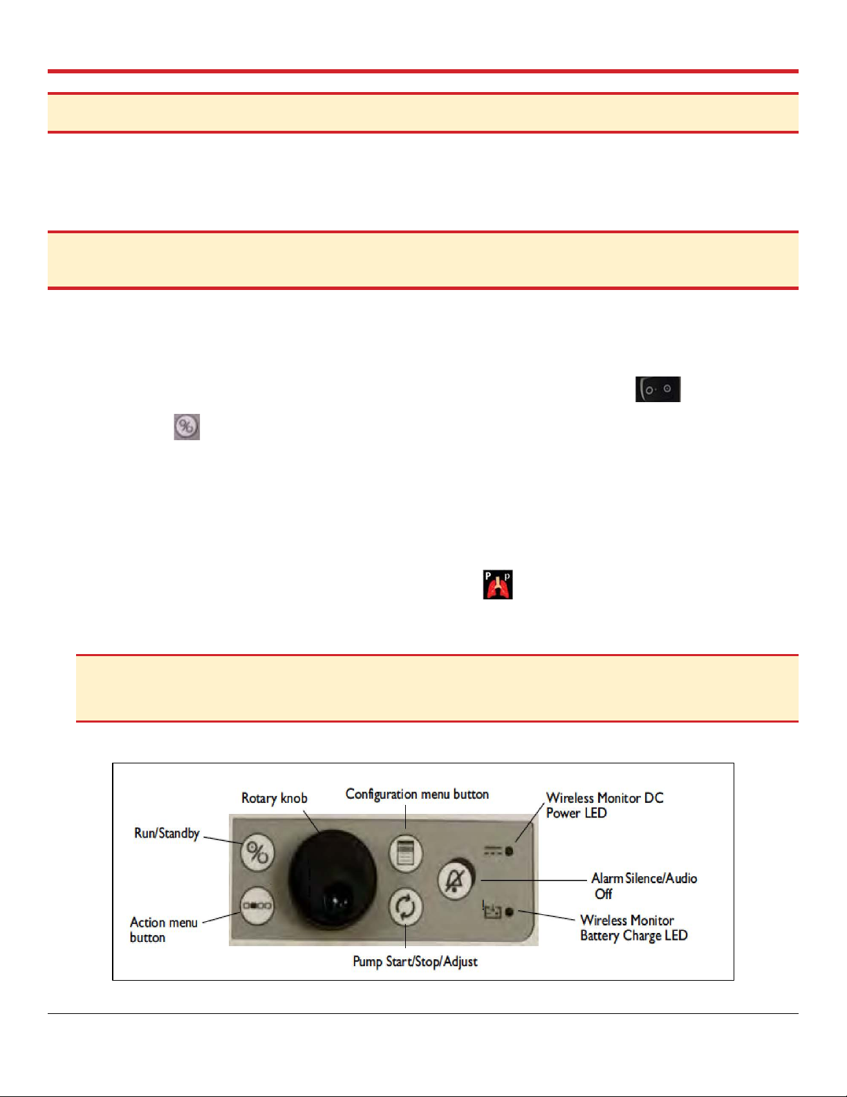
1. Make sure the Wireless Monitor is docked to the OCS™ Lung Console and the lung system is
in Standby Mode. Figure 4.10 shows the controls of the Wireless Monitor.
2. Make sure the ON/OFF switch on the OCS™ Lung Console is in the ‘ON’ position.
3. Press the button on the Wireless Monitor. The system performs a Self Test and displays
system transitional status messages. If errors are encountered, error messages are displayed.
4. If displayed errors indicate problems, refer to the Troubleshooting chapter in the TransMedics
Technical User Guide: OCS™ Lung System.
5. If no errors display, select “New Session File” to proceed.
6. Start a “New Session File” and confirm the following:
• Ventilator Mode is defaulted to Pause Preservation.
• NO (+++) OR (- - -) are displayed on the Wireless Monitor for Mean PAP or airway
pressure readings.
CAUTION—If the system detects an issue during the Self Test, a message is displayed with information about
the issue until it is resolved. To resolve the issue, follow the steps in the troubleshooting section of the TransMedics
Technical User Guide: OCS™ Lung System.
Figure 4.10: Wireless Monitor Controls
PN 100004071, Rev 5 Page 27
Chapter 4: Activities Performed at Donor Site
NOTES—
The Run/Standby button on the Wireless Monitor will NOT FUNCTION unless the Wireless Monitor is DOCKED on
the OCS™ Lung System.
At the beginning of the session, the system may display messages and sound alarms related to sensor probes. These
messages and alarms can be disregarded. For details of system initialization and messages, see the TransMedics
Technical User Guide: OCS™ Lung System.
4.5. Preparing the OCS™ Lung System for Lung Instrumentation
This section provides instructions for preparing the lung system for lung instrumentation.
4.5.1. Priming the OCS™ LPM
Priming overview settings are listed in Table 4.1. After the LPM and the probes are installed and the
Self Test is complete, the lung system will default to Pause Preservation Ventilation Mode, and the
module will be ready to be primed.
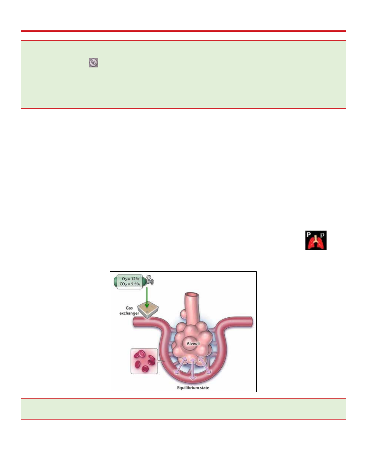
4.5.2. Pause Preservation Mode
In Pause Preservation Mode, the bellows remain stationary and the OCS™ Lung System achieves a
static level of lung inflation. Pause Preservation enables oxygenation of the perfusate prior to lung
instrumentation using the Lung Preservation Gas. As the lung is perfused, the dissolved gas in the
perfusate is exchanged across the alveoli (Figure 4.11) with the gas in the static
breath. The Wireless Monitor icon for Pause Preservation Mode is shown here at the
right:
Figure 4.11: Pause Preservation Mode
NOTE—Use aseptic technique when performing the following priming procedure.
PN 100004071, Rev 5 Page 28

Chapter 4: Activities Performed at Donor Site
Settings
OCS™ Lung System Recommendations
Priming
• 1.5-2 L of buffered* OCS™ Lung Solution
• +3 units of pRBCs
• Medications (additives & prophylactic medications)
*Use 10 mEq of NaHCO3 or 1 mmol of THAM/L (tromethamine) to buffer the
OCS
TM
Lung Solution immediately before usage.
Temperature
• Set to 32°C in Preservation settings
Pump Flow
• Increase to 3 L/min to de-air & mix perfusate
• After de-airing, lower to 1 L/min until temperature reaches 32°C
• Lower Pump flow to 0.5 L/min before lungs are instrumented
Preservation Gas Flow
Open the Lung Preservation Gas cylinder & set flow to 300 ml/min
Ventilation
Pause Preservation
Recommended Ventilation Settings
Preservation Mode
Monitoring Mode
Tidal Volume (TV)
6 ml/kg (ideal body weight) #
Positive End Expiratory Pressure
(PEEP)
7 cmH2O
5 cmH2O
Respiratory Rate (RR)
12 BPM
# Devine’s Ideal Body Weight Formula (see Appendix B)
Table 4.1: Priming Overview
#NOTE—For a suggested ideal body weight formula, see Appendix B: Body Weight Formula (Devine’s Formula for
donor’s height above 150 cm (5 feet).
4.5.3. Priming the LPM
For priming the LPM, the Lung Perfusion Initiation Set needs to be used to deliver the lung perfusate
(OCS™ Lung Solution and RBCs) to the LPM as follows:
1. Open one of the packaged Dual Vented Prime Lines in the Lung Perfusion Initiation Set.
2. Close the clamps on the Dual Vented Prime Line.
3. Insert the piercing spike of the Dual Vented prime line into the buffered OCS™ Lung Solution
bags, using a twisting motion until the set is firmly seated.
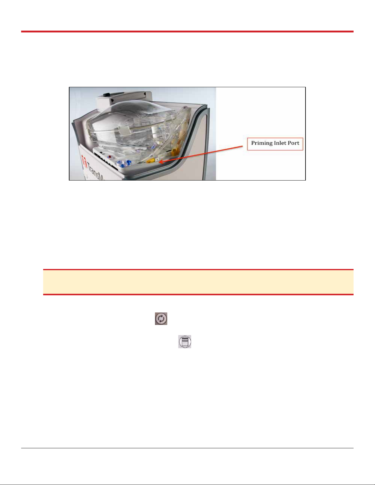
4. Remove the yellow protective cap from the LPM’s Priming Inlet Port (Figure 4.12).
5. Uncover and connect the outlet from the Dual Vented Prime line to the Priming Inlet Port.
6. When ready to prime the LPM, open the Dual Vented Prime Line’s clamp and add 1.5-2 L of
buffered OCS™ Lung Solution to the reservoir.
7. Add the 3 units of ABO-compatible (to the recipient) leukocyte-reduced pRBCs after adding
the OCS™ Lung Solution using a set of the Dual Vented Prime Lines.
PN 100004071, Rev 5 Page 29
Chapter 4: Activities Performed at Donor Site
8. Clamp and cover the Priming Inlet Port of the LPM with one of the provided spare covers on
the modules. Reposition the covered Priming Inlet Port back in its recess.
9. Turn on the Pump to start circulating, mixing, and warming the perfusate.
Figure 4.12: LPM Priming Inlet Port
4.5.4. Start of Perfusate Circulation
1. Make sure the gas exchanger vent on the LPM remains open.
2. Ensure that the Termination Flush Stopcock is closed.
3. Open the Preservation Gas cylinder by turning its valve 180 degrees in a counter-clockwise
direction.
4. Always keep the OCS™ Lung System connected to AC power while at the donor site and
during system priming.
CAUTION—Ensure that the Flush stopcock is closed before turning the Pump on to avoid pumping the
perfusate out of the module if the cap on the Termination Flush Port is removed.
5. Start circulation with the following settings:
a. Press the Pump adjust button on the Wireless Monitor and adjust Pump flow to 3.0
L/min for few minutes to de-air the module, mix and warm the perfusate.
b. Press the Configuration menu button , highlight and select the Preservation tab using
the rotary knob. Adjust the settings as follows for the Preservation settings:
- Ensure that the temperature is set to 32°C.
- Ensure that the gas flow rate is set to 300 mL/min (Lung Preservation Gas flow rate).
- Set the ventilation setting, as listed in Table 4.1, using the rotary knob to highlight,
select, and adjust all settings.
- Ensure that you confirm your settings by highlighting and pressing “accept” displayed
at the bottom of each menu using the rotary knob.
PN 100004071, Rev 5 Page 30
 Loading...