

Page 1
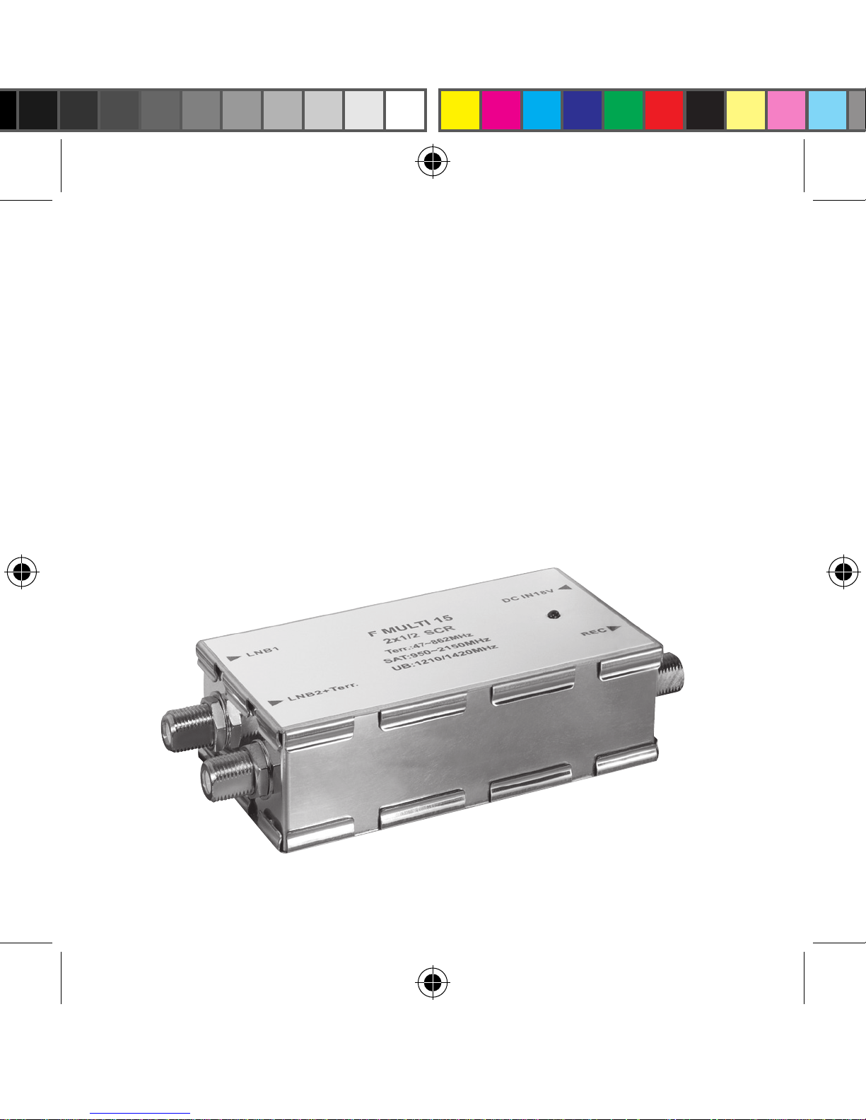
SATELLITE MULTISWITCH
User`s manual
F MULTI 15
FMULTI5_Manual-en_99.indd 1
08.11.2013 12:02:17
Page 2
!
Attention! Read the instructions carefully and completely.
It is part of the product and contain important information
for the proper installation and use. Keep these operating
instructions in conjunction with the product.
Contents: Site
1. Introduction 3
2. Product Features 3
3. Installation diagram 4
4. Installation 6
5. Safety instruction 7
6. Trouble shooting and maintenance 9
7. Technical data 9
2
FMULTI5_Manual-en_99.indd 2
08.11.2013 12:02:17
Page 3

1. Introduction
Relaying satellite signals from the rooftop dish to multiple recei-
vers around the home, Digital Video Recorders (DVR) or throug-
hout an apartment block is an expensive proposition for system
installers. The Unicable multiswitch F MULTI 15 addresses this
problem by combining up to two input signals onto a single cable.
These signals are then decoded by a corresponding number of
tuners, potentially distributed across many set-top boxes.
3
2. Product Features
1. • Two sattelite signal inputs
• One sattelite / terrestrial input
2. One common Unicable-Output for
Sat / terrestrial signal
3. Supports the following connection options:
• Multiswitch • Quad LNB • Quattro LNB
4. Each SAT input supports 13/18 V DC, 0/22 KHz
and DiSEqC (A/B)
5. The product is supplied by an external 18 V / 1.2 A
power supply.
6. Max. 2 user bands for 2 subscriber / receivers.
FMULTI5_Manual-en_99.indd 3
08.11.2013 12:02:17
Page 4
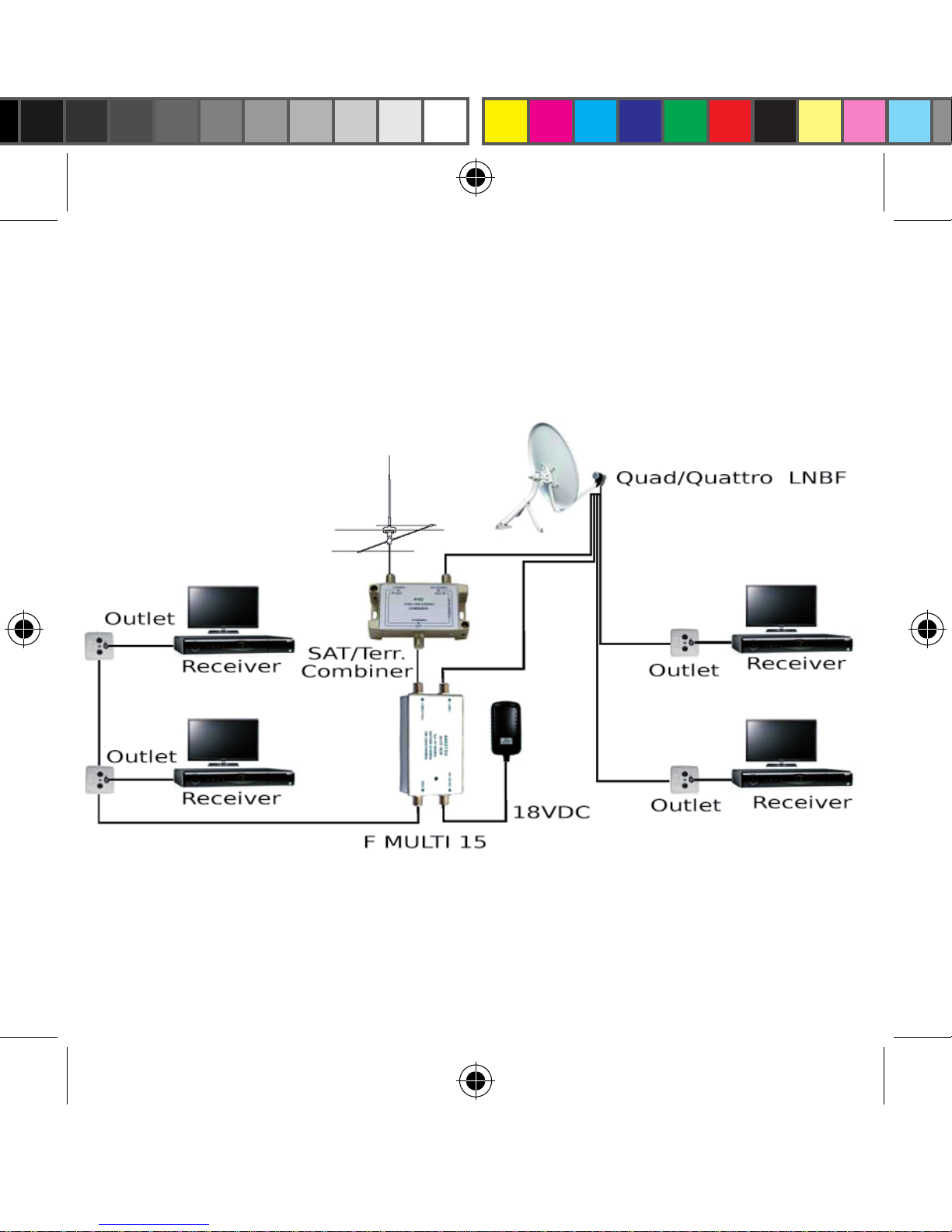
3. Installation diagram
1. F MULTI 15 with LNB
4
FMULTI5_Manual-en_99.indd 4
08.11.2013 12:02:17
Page 5
!
Attention! Receiver work with F MULTI 15 must with
Unicable function. It must be DC-Pass between IN and
OUT, also IN and SAT for all Outlets to work with
F MULTI 15. SAT/Terr.
Combiner should be DC-Pass between SAT port and
Common port.
2. F MULTI 15 with multiswitch
5
FMULTI5_Manual-en_99.indd 5
08.11.2013 12:02:18
Page 6
4. Installation
1. Please refer above installation diagram in selection 3 to
install your system.
2. Power on all receivers and 18 V DC power adapter.
3. If power from receivers and 18 V DC power adapter exist,
green LED on multiswitch should be turn on.
4. Any DiSEqC commands between receivers and multiswitch,
greenLEDwillbeashing.
5. If no power from receivers, multiswitch will be turn off.
Green LED will be turn off and it means F MULTI 15 is
turned off to power-saving mode.
6. No matter how the power is, the terrestrial signal is passive
and always working.
7. Setup in receiver menu:
Please refer to the manual of your receiver to enter the settings..
• Select the satellite you wish to receive.
• Select the LNB type as Unicable LNB or Unicable Multiswitch.
• Select for the rst receiver the following settings User ID:
0, User Band: 1210 MHz
• for the second receiver User ID: 1, User Band: 1420 MHz
• Start the search. After completion, save all program locations.
6
FMULTI5_Manual-en_99.indd 6
08.11.2013 12:02:18
Page 7
5. Safety instruction
1. Please separate the product before any operation from
stream.
2. Verify that the wall or the support to which the device will
bexedisstrongenoughtoendureitsweight.
3. Always connect the device to a proper socket.
Please refer to the technical data for more details.
4. The product is exclusively for indoor use, therefor it dosen´t
protect against any contact with water or steam.
5. Please note when installing:
• It is not exposed directly to the sunlight, since an excessive heating
could be detrimental to its normal operation.
• It is not close to any direct source of heat like heaters, fireplaces or
similar equipment. (please refer to the operating temperature for
more information)
• It is at a proper distance from other electrical equipment to avoid
possible electrical interference.
• There is adequate ventilation to guarantee the correct exhaust of the
heat during the normal operation. No ignitable material is on or close
to the product to avoid the danger of fire.
• Any direct or indirect contact with any kind of liquid substances is
prohibited to prevent short circuit, discharge or electrical leakage.
7
FMULTI5_Manual-en_99.indd 7
08.11.2013 12:02:18
Page 8
6. Onlyoperatethedevicewiththespeciedmainsvoltage.
Do not connect the device to the power socket before all the
installation procedures have been completed.
7. Before connecting the product to the power supply, verify
that the external case is perfect and the connecting cable
does not show any damage or defect.
8. In order to avoid detrimental attenuations that could
compromisetheefciencyoftheequipment,route
cables along the shortest way and avoid sharp bends.
9. For the installation of the product, it is recommended to
contactaeldservicequaliedtoreleasetheproper
system’s declaration of conformity.
10. If the equipment is not in use, please unplug.
8
FMULTI5_Manual-en_99.indd 8
08.11.2013 12:02:18
Page 9
6. Trouble shooting and maintenance
7. Technical data
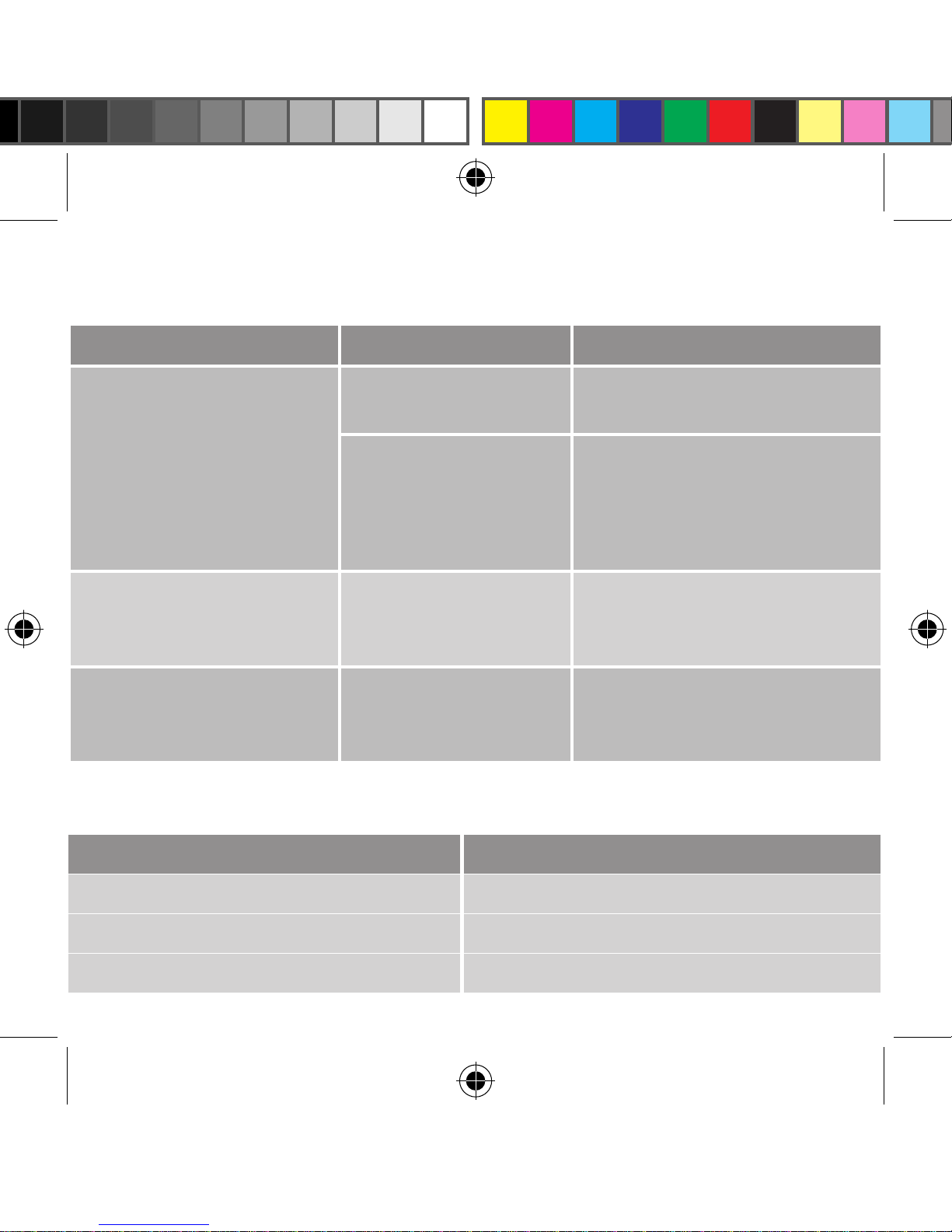
Failure Possible causes Solution
No image, no sound
or no signal
No Power Supply
Please check all power on
each cable.
Defective or missing
cables.
Please connect required
cables or replace by good
cables.
Unsatble image, sound
or signal
Signal too weak or
noise
Please use shorter cables,
or replace defective cables
and connectors.
Program channel
interference by another
receiver
Wrong setting for
User ID and User
Band
Please follow installation
instruction to check the
setting.
Item / Specication Typical Value
Dimension without PSU 110 mm (L) x 52 mm (W) x 30 mm (H)
Weight 120 g
Working Temperature -20 ~ +55 °C
9
FMULTI5_Manual-en_99.indd 9
08.11.2013 12:02:18
Page 10
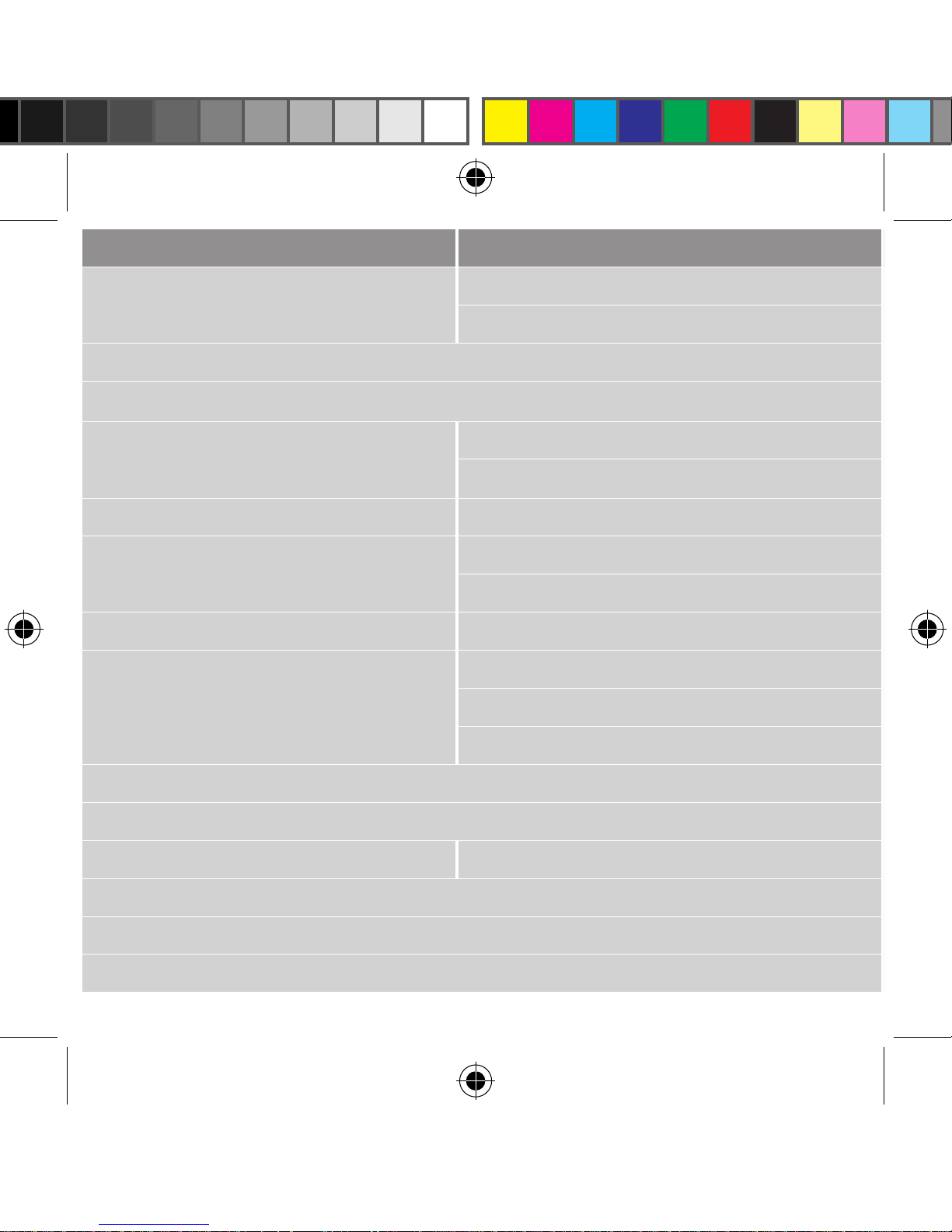
Item Specication
Typical Value Max. Value Remark
Frequency Range
Terrestial (TER)
Satellite (SAT)
Input Ports
LNB 1, LNB 2 + TER, DC_IN 18 V
Output Ports
1 Unicable Output / 2 Users
Gain
TER
- 5 dB ≥-7dB Passive
SAT
5 ± 2 dB 5 ± 3 dB
Isolation LNB 1 / LNB 2
40 dB 35 dB
Return loss
Input
8 dB 6 dB
Output
8 dB 6 dB
Max. O/P Level SAT
93 dBµV 90 dBµV 35 dB IMA
TrafcIndicator
(ᵩ3mmGreenLED)
ON
Flash
DiSEqC command received
OFF
Passive terrestrial signal working only
DC support to LNB inputs
13/18 V DC, 0/22 KHz, DiSEqC (A/B)
Command from Subscriber
EN 50494 (Extension DiSEqC 1 Standard)
User Band 0 / 1 F MULTI 15
PIN Code for MDU Installation
Power consumtion without LNB
External Switching Mode Power Supply
100 ~ 240 VAC / 47 ~ 63 Hz, 18 V / 1.2 A Wall mount
10
FMULTI5_Manual-en_99.indd 10
08.11.2013 12:02:18
Page 11
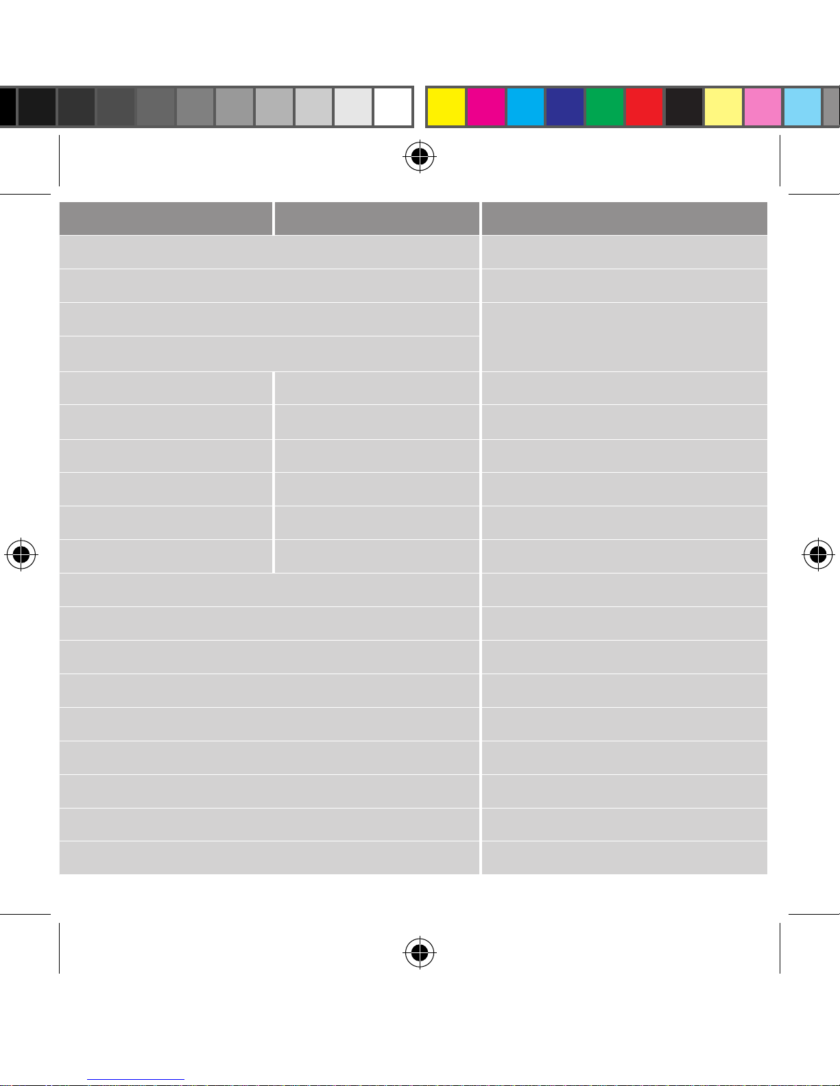
Typical Value Max. Value Remark
5 ~ 862 MHz
950 ~ 2150 MHz
LNB 1, LNB 2 + TER, DC_IN 18 V
F-Type female connector
1 Unicable Output / 2 Users
- 5 dB ≥-7dB Passive
5 ± 2 dB 5 ± 3 dB
40 dB 35 dB
8 dB 6 dB
8 dB 6 dB
93 dBµV 90 dBµV 35 dB IMA3 @ 50083-3
Normal State Powwered by PSU & Receiver
DiSEqC command received
Passive terrestrial signal working only
13/18 V DC, 0/22 KHz, DiSEqC (A/B)
EN 50494 (Extension DiSEqC 1 Standard)
1210 MHz / 1420 MHz
6F / DE
85 mA Max. @ 18 V Ext. PSU
100 ~ 240 VAC / 47 ~ 63 Hz, 18 V / 1.2 A Wall mount
11
FMULTI5_Manual-en_99.indd 11
08.11.2013 12:02:18
 Loading...