

Transition Networks TNIC-1500-AF, TNIC-1500TA2, TNIC-1500-TF, TNIC-PCI-T, TNIC-1500T User Manual
Page 1

For assistance in installing, using, or
maintaining the TRANSITION Networks
TNIC Adapter Card, contact
TRANSITION Networks Technical
Support
at:
(800) 260-1312
or contact your local distributor.
7355.B
(TNIC-1500T, TNIC-1500TA2, TNIC-1500-TF,
TNIC-1500-AF, TNIC-PCI-T)
TNIC Adapter Card
TNIC ADAPTER CARD
SPECIFICATIONS
Standards
IEEE 802.2, 802.3
Physical
Dimensions
4.80" X 2.77" X 0.95" (122mm x 70mm x 24mm)
MTBF
TNIC-1500T 2,300,000 hours
TNIC-1500TA2 1,660,000 hours
TNIC-1500-TF 762,000 hours
TNIC-1500- AF 762,000 hours
TNIC-1500-PCI-T 1,179,000 hours
Environment
Temperature: 0-50°C (32° to 122° F )
Humidity 10-90%, non condensing
Altitude 0-10,000 feet
Warranty
2 years
Page 2

TNIC Adapter Card
28
10Base2 Cable Specifications
The physical characteristics of the 10Base2 cable must meet or exceed IEEE 802.3
10Base2 specifications.
Cable Characteristics:
Cable type: Stranded Coaxial RG58 (ThinNet)
Impedance: 50 Ω @ 10 MHz
Mutual Capacitance: 24 pF/ft ±20% @ 10 MHz
Maximum Cable Length
: 185 meters (610 feet)
Maximum number network connections:30
Minimum distance between connections: 0.5 meters (1.6 feet)
Terminate 10Base2 cable at one end using a 50 ohm terminator and at the
other end using a 50 ohm terminator grounded to earth ground.
10BaseT Cable and Connector Specifications
The physical characteristics of the 10BaseT cable must meet or exceed IEEE 802.3
10BaseT specifications.
10BaseT Cable Characteristics:
Category 3 wire or better is required; category 5 wire is recommended. Either
shielded twisted pair (STP) or unshielded twisted pair (UTP) can be used. DO
NOT USE FLAT OR SILVER SATIN WIRE.
Category 3:
Gauge 24 to 22 AWG
Attenuation 28 dB/1000’ @ 10 MHz
Differential Characteristic Impedance 100 Ω ±10% @ 10 MHz
Category 5:
Gauge 24 to 22 AWG
Attenuation 20 dB/1000’ @ 10 MHz
Differential Characteristic Impedance 100 Ω ±10% @ 10 MHz
Maximum Cable Length: 100 meters (330 feet)
10BaseT Connector Characteristics:
The two active pairs in a 10BaseT network are pins 1 & 2 and pins 3 & 6. Use
only dedicated wire pairs (such as blue/white & white/blue, orange/white &
white/orange) for the active pins. 10BaseT cable for unlike devices (such as
hub to terminal device) must be configured as straight through; 10BaseT cable
for like devices (such as hub to hub or terminal device to terminal device) must
be configured as crossover.
Twisted
Pair #1
Twisted
Pair #2
Crossover Cable
1
2
3
6
1
2
3
6
1
2
3
6
Twisted
Pair #1
Twisted
Pair #2
Straight Through Cable
1
2
3
6
CAUTION: RJ connectors are NOT INTENDED FOR
CONNECTION TO THE PUBLIC TELEPHONE
NETWORK. Failure to observe this caution could result
in damage to the public telephone network.
Compliance Information
UL Listed
C-UL Listed (Canada)
CISPR/EN55022 Class A
FCC Regulations
This equipment has been tested and found to comply with the limits for a class
A digital device, pursuant to part 15 of the FCC rules. These limits are
designed to provide reasonable protection against harmful interference when
the equipment is operated in a commercial environment. This equipment
generates, uses, and can radiate radio frequency energy and, if not installed
and used in accordance with the instruction manual, may cause harmful
interference to radio communications. Operation of this equipment in a
residential area is likely to cause harmful interference, in which case the user
will be required to correct the interference at the user’s own expense.
Canadian Regulations
This digital apparatus does not exceed the Class A limits for radio noise for
digital apparatus set out on the radio interference regulations of the Canadian
Department of Communications.
European Regulations
Warning
This is a Class A product. In a domestic environment this product may cause
radio interference in which case the user may be required to take adequate
measures.
Copyright Restrictions
© 1995, 1996 TRANSITION Networks Inc.
All rights reserved. No part of this work may be reproduced or used in any
form or by any means – graphic, electronic, or mechanical – without written
permission from TRANSITION Networks Inc.
Trademark Notice
All registered trademarks and trademarks are the property of their respective
owners.
Der Anschluss dieses Gerätes an ein öffentlickes
Telekommunikationsnetz in den EG-Mitgliedstaaten verstösst gegen die
jeweligen einzelstaatlichen Gesetze zur Anwendung der Richtlinie
91/263/EWG zur Angleichung der Rechtsvorschriften der
Mitgliedstaaten über Telekommunikationsendeinrichtungen
einschliesslich der gegenseitigen Anerkennung ihrer Konformität.
Page 3

Table of Contents
1 INTRODUCTION . . . . . . . . . . . . . . . . . . . . . . . . . 1
TNIC Adapter Cards/Software . . . . . . . . . . . . . . . . . . . . . . . .1
The TNIC Family of Adapter Cards . . . . . . . . . . . . . . . . . . . .2
LED Status Indicators . . . . . . . . . . . . . . . . . . . . . . . . . . . . . . .3
TNIC Adapter Cards INSTALL Software . . . . . . . . . . . . . . . . .4
INSTALL Main Window . . . . . . . . . . . . . . . . . . . . . . . . . . . . . .5
INSTALL Automatic Card Configuration Window . . . . . . . . . . .7
INSTALLCustom Card Configuration Window . . . . . . . . . . . . . .8
INSTALL TNIC Driver Installation Window . . . . . . . . . . . . . . . .9
INSTALL Diagnostics Window . . . . . . . . . . . . . . . . . . . . . . . .10
2 SITE CONSIDERATIONS. . . . . . . . . . . . . . . . . . . 11
3 INSTALLATION. . . . . . . . . . . . . . . . . . . . . . . . . . 12
Unpacking TNIC Adapter Card . . . . . . . . . . . . . . . . . . . . . .12
Setting Jumpers on 1500-x . . . . . . . . . . . . . . . . . . . . . . . . . .13
Installing TNIC Adapter Card in PC . . . . . . . . . . . . . . . . . . .16
Installing Configuration and Driver Software in PC . . . . . . .17
Connecting Cable to TNIC Adapter Card . . . . . . . . . . . . . . .18
4 OPERATION. . . . . . . . . . . . . . . . . . . . . . . . . . . . 22
5 MAINTENANCE . . . . . . . . . . . . . . . . . . . . . . . . . 24
Fault Isolation . . . . . . . . . . . . . . . . . . . . . . . . . . . . . . . . . . .24
Technical Support Contact . . . . . . . . . . . . . . . . . . . . . . . . .24
POLICY AND PROCEDURE . . . . . . . . . . . . . . . . . . . . . . . . . 25
ETHERNET CABLE SPECIFICATIONS. . . . . . . . . . . . . . . . . . 27
TNIC ADAPTER CARD SPECIFICATIONS. . . . . . . . . . . . . . 29
TNIC
i
27
Adapter Card
ETHERNET CABLE SPECIFICATIONS
AUI Cable and Connector Specifications
The cable is a special 4-pair individually shielded with an overall braided
shield.
Maximum AUI Cable Length: 50 meters (165 feet)
AUI Connector Characteristics:
AUI Port: Male DB-15 with locking posts.
AUI Connection: Cable shell must be grounded.
Connector Legend: 1 Logic Ref. 6 Power Return 11 Logic Ref
2 Collision+ 7 N/C 12 Receive
3 Transmit+ 8 Logic Ref. 13 Power
4 Logic Ref. 9 Collision-- 14 Logic Ref.
5 Receive+ 10 Transmit- 15 N/C
10BaseFL Cable and Connector Specifications
The physical characteristics of the 10BaseFL cable must meet or exceed IEEE
802.3 10BaseFL specifications.
10BaseFL Cable Characteristics:
Fiber Optic Cable Recommended: 62.5/125 µm multimode fiber
Optional: 100/140 µm multimode fiber
85/125 µm multimode fiber
50/125 µm multimode fiber
Fiber Optic Transmitter Power: Average power: -15.0 dBm
Peak power:-12.0 dBm ±1dBm
Fiber Optic Receiver Sensitivity: Average sensitivity: -27.4 dBm
Bit error rate: ≤10
-10
Maximum Cable Length: 2000 meters (6500 feet)
10BaseFL Connector Characteristics:
ST type connectors (SMA type available upon request)
10Base5 Cable and Connector Specifications
The physical characteristics of the 10Base5 cable must meet or exceed IEEE 802.3
10Base5 specifications.
10Base5 Cable Characteristics:
Cable type: RG8 Solid Coaxial (ThickNet)
Impedance: 50 Ω @ 10 MHz
Capacitance: 26pF/ft
Maximum Cable Length: 500 meters (1650 feet)
Maximum number network connections: 100
Minimum distance between connections: 2.5 meters (8.2 feet)
Terminate 10Base5 cable at one end using a 50 ohm terminator and at the
other end using a 50 ohm terminator grounded to earth ground.
Maximum number of terminal devices on Ethernet network: 1024
Page 4

TNIC
26
1
Adapter Card
1. INTRODUCTION
This guide is intended for the system or network administrator
responsible for installing and monitoring a TRANSITION Networks
TNIC Adapter Card. A working knowledge of local area network (LAN)
operations, including familiarity with communications protocols used
on interconnected LANs, is assumed.
TNIC Adapter Cards/Software
The TRANSITION Networks TNIC Family of Adapter Cards (TNIC1500T, TNIC-1500TA2, TNIC-1500-TF, TNIC-1500-AF, TNIC-PCI-T),
provides an integrated hardware/software interface between a PC and
various 802.3 Ethernet compliant media.
Driven by software installed in the PC in which the adapter card is
installed, the TNIC Adapter Card provides connection to the following
Ethernet media:
• 10BaseT
• 10Base2
• 10Base5
• 10BaseFL
TN’s total liability in connection with the products and installation thereof to
all persons and from all causes in the aggregate whether in contract, tort, or
strict liability shall not exceed the amount paid to TN for the product directly
related to the alleged damage. However, in no event shall TN have any
liability to a customer or any third party with respect to a product
manufactured in accordance with customer’s specifications.
C. Return Procedure
Before TN item(s) can be returned, a Credit Return Authorization (CRA),
Return Material Authorization (RMA), or Material Repair Authorization
(MRA)number must be obtained from TRANSITION Networks (TN) or the
distributor of origin.
Locate the serial number(s) of the item(s) to be returned. From the item serial
number, TN or the distributor will verify the return status and provide the
appropriate number to the End User. The three types of return numbers are
listed below:
• A Credit Return Authorization (CRA) number can only be requested from
your distributor. This CRA number will only be issued to distributors for
item(s) within 90 days from the original ship date. Under no
circumstances will a CRA number be issued directly to the End User. The
return item(s) must be shipped freight prepaid, by the End User or the
Distributor to TN.
• A Return Material Authorization (RMA) number can be requested from TN
or your distributor. This RMA number is only issued for item(s) after 90
days from the original ship date but prior to the expiration of the warranty
period. The return item(s) must be shipped freight prepaid, by the End
User or Distributor, to the TN address below:
TRANSITION Networks Inc.
6475 City West Parkway
Eden Prairie, MN 55344 USA
TRANSITION Networks will repair or replace the unit, at its discretion,
and cover the cost of the return freight to the distributor or End User who
was issued the RMA number.
• A Material Repair Authorization (MRA) number can be requested from TN
or your distributor. This MRA number is only issued for out-of-warranty
item(s). The return item(s) must be shipped freight prepaid, by the End
User, to the TN address above. The sender will be contacted by TN after
the item(s) have been received, inspected, and a cost estimate of the
repair has been determined. The repair charges may be billed, with
approval, through your distributor or prepaid/C.O.D. basis through the
End User. In either case, charges will include freight, both ways, and
repair charges.
The return authorization number is only valid for 60 days from the date of
issuance. Please list this number on the outside of the carton and/or packing
list. Include a copy of the original invoice or packing slip to expedite
processing.
D. Restocking Fee
All returns for credit must be received in the same condition as originally
shipped. If TN determines that a returned product is damaged due to improper
packaging or if the item is functional and returned because of customer error,
inability to use, etc., TN reserves the right to charge a minimum 15% ($10.00
minimum per item) restocking fee, the payment of which is a condition
precedent to the repair and/or return of the product.
Page 5
TNIC
2
25
Adapter Card
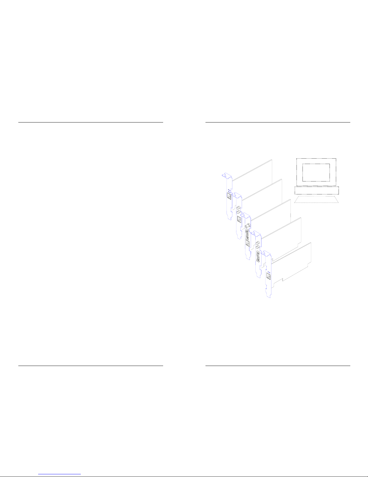
The TNIC Family of Adapter Cards
The naming convention for the TRANSITION Networks TNIC Series
1500 Adapter Cards identifies the connectors:
T = twisted pair (10BaseT) 2 = thinet (10Base2)
A = AUI (connects to 10Base5) F = fiber (10BaseFL)
In installations of TNIC Adapter Cards with more than one media
connector, only one connector (site-selectable using jumpers) can be
active at a time.
TNIC-PCI-T
TNIC-1500-AF
TNIC-1500-TF
TNIC-1500TA2
TNIC-1500T
Policy And Procedure
A. Limited Warranty
TRANSITION Networks (TN) warrants, for a period of two years (with the
exclusion of five years for passive balun products) from the date of shipment to
the original purchaser and at the original point of installation, that products of
TN’s design will be free from defects in materials and workmanship and in
conformity with TN’s specifications. TN’s sole warranty with respect to products
manufactured or assembled by TN in accordance with a customer’s
specifications is a two year warranty that such goods conform to such
specifications. These warranties do not extend to goods that have been subject
to alterations, misuse, accident, tampering, improper maintenance, improper
installation or abuse.
THE ABOVE WARRANTY IS EXCLUSIVE AND EXTENDS ONLY TO PRODUCTS
ASSEMBLED BY TN, AND TO THE EXTENT PERMITTED BY LAW, TN DOES NOT
MAKE AND DISCLAIMS ALL OTHER WARRANTIES (EXCEPT TITLE), EXPRESSED
OR IMPLIED, INCLUDING BUT LIMITED TO ANY WARRANTY OF
DESCRIPTION, MERCHANTABILITY, FITNESS FOR A PARTICULAR PURPOSE
OR NON-INFRINGEMENT AND ANY WARRANTY BASED UPON PRIOR
WRITTEN OR ORAL REPRESENTATIONS REGARDING SUCH PRODUCTS
MADE BY TN, ITS EMPLOYEES, AGENTS, OR REPRESENTATIVES.
B. Limitations and Exclusions
If customer believes any goods sold hereunder are defective pursuant to the
warranty and within the warranty period set forth above, the customer must
notify TN within such period. TN will promptly issue a return form for such
goods. Upon receipt of the form, customer is to promptly return the allegedly
defective goods at customer’s expense and shipped prepaid to your distributor or
TN (refer to the next subsection C, Return Procedure).
No goods will be accepted for return unless a prior return form is obtained from
TN, freight charges have been prepaid by customer. TN or the distributor shall,
at its option, either (i) repair such goods free of charge if warranty within two
years, (ii) repair such goods at a minimum of $200 (Two Hundred dollars) per
item if warranty expired, (iii) replace such goods free of charge, or (iv) accept
the return of such goods and credit current price therefore to the customer.
THIS IS THE EXCLUSIVE REMEDY FOR ANY BREACH OF WARRANTY. IN NO
EVENT SHALL TN BE LIABLE FOR SPECIAL, INDIRECT, INCIDENTAL OR
CONSEQUENTIAL DAMAGES OF ANY KIND, WHETHER FOR BREACH OF ANY
WARRANTY, FOR BREACH OR REPUDIATION OF ANY OTHER TERM OR
CONDITION OF SALE, FOR NEGLIGENCE , ON THE BASIS OF STRICT
LIABILITY, CONTRACT, OR OTHERWISE AND IRRESPECTIVE OF WHETHER TN
IS INFORMED BY CUSTOMER OF THE POSSIBILITY OF SUCH DAMAGES IN
ADVANCE OF THIS SALE.
The sole purpose of this remedy shall be to provide the customer with the
replacement or repair of non-conforming goods in the manner provided here-in.
This exclusive remedy shall not be deemed to have failed of its essential purpose
so long as TN is willing and able to repair or replace the non-conforming goods
or refund the purchase price therefore in the manner provided herein.
TN reserves the right to inspect products claimed to be defective under warranty
either at the customer’s location or at TN's plant. TN assumes no liability for
labor charges incidental to the adjustment, service, repairing, removal or
replacement of the product or other costs, or the expense of repairs made
outside of its factory except when made pursuant to TN's prior written consent.
All returns must be received in the same condition as the original shipment.
Page 6

TNIC
24
3
Adapter Card
5. MAINTENANCE
WARNING: DO NOT, UNDER ANY CIRCUMSTANCES,
attempt to repair the TNIC Adapter Card. Failure to observe
this warning could result in personal injury or death from
electrical shock.
NOTE: Failure to observe the above warning will immediately void
the warranty.
Fault Isolation
If two network devices fail to communicate through the TNIC
Adapter Card, consider the following:
• Are the LEDs described in the previous section functioning
properly?
• Do network devices have Link Integrity enabled?
• Do network devices communicate when the TNIC Adapter
Card is not installed between them?
• Is flat or “silver satin” wire used in site internal wiring?
• Are internal wiring patch cords, punch down blocks, and
wall jacks properly pinned or configured?
• Is the AUI cable unbroken and properly connected?
• Are network interface cards properly configured?
Technical Support Contact
For assistance in fault isolation and in maintaining the TNIC Adapter
Card, contact:
Technical Support (800) 260-1312
or your local distributor.
LED Status Indicators
TNIC PCI Card
LINK Illuminated when link is
established.
Active Flashes during data transmission
and reception.
TNIC 1500T Card
LINK Illuminated when link is
established.
Transmit Flashes during data
transmission.
Receive Flashes during data
reception.
Polarity OK Illuminated when
10BaseT connection is
established.
TNIC 1500n Cards
UTPD ENABLE Illuminated when AUI
connection is
established.
XMIT Flashes during data
transmission.
POL OK Illuminated when
10BaseT connection is
established.
RCV Flashes during data
reception.
LINK Illuminated when link
is established.
Active
LINK
LINK
Polarity OK
Receive
Transmit
UTPD ENABLE
XMIT
POL OK
RCV
LINK
UTPD ENABLE
XMIT
POL OK
RCV
LINK
Page 7

TNIC 1500n Cards
UTPD ENABLE Illuminated when
AUI connection is
established.
XMIT Flashes during data
transmission.
POL OK Illuminated when
10BaseT connection
is established.
RCV Flashes during data
reception.
LINK Illuminated when
link is established.
TNIC
4
23
Adapter Card
TNIC Adapter Card INSTALL Software
TRANSITION Networks’
INSTALL software, shipped
as a set of two Universal
TNIC Driver Disks (#7210),
provides a graphical
interface for configuring the
TNIC Adapter Card and for
installing a software driver.
(Disk 2 also provides
detailed documentation that
may be required for complex
driver installations.)
The INSTALL utility
automatically scans the
system bus (ISA, VL, or PCI)
to identify which TNIC
adapter card is present, then configures the adapter card and
installs driver software on the system hard drive.
The following drivers can be installed using the INSTALL utility:
• Novell NetWare DOS ODI client driver
• NDIS 2.01 driver
• Packet driver
For other environments, see the appropriate driver installation
instructions in the MS-Word file: TNIC.DOC on Disk 2 of the
Universal TNIC Driver Disk. Using the instructions provided, the
following drivers can be installed through the INSTALL utility or
can be installed manually at the command-line prompt:
• NDIS 3.x driver
• SCO Unix LLI driver
• Novell UnixWare DLPI driver
• SunSoft Solaris driver
UTPD ENABLE
XMIT
POL OK
RCV
LINK
UTPD ENABLE
XMIT
POL OK
RCV
LINK
Page 8

TNIC
22
5
INSTALL Main Window
Before the Main window appears, the utility searches for a TNIC
adapter card in the system. If one is not found, an error screen is
displayed telling the user to install the adapter card before using the
utility. If only one Ethernet card is found and a conflict-free
configuration is determined, the Automatic, Custom, and Drivers
buttons are enabled. If more than one card is found or if the
configuration has conflicts, only the Custom and Drivers buttons are
enabled.
Depending on the TNIC adapter card (and the configuration buttons
enabled), the utility allows the user to view and modify the I/O
Address, IRQ Level, and DMA Channel settings and determines
settings that will configure the TNIC card to be compatible with other
card settings in the system.
If multiple adapter cards are present, the INSTALL utility permits the
user to select each adapter card in turn and to modify the adapter
card configuration settings as needed.
X
TRANSITION
networks
TNIC Family Installation Main Window
4. OPERATION
The TNIC Adapter Card requires no intervention beyond occasionally
monitoring the Power and Link/Transmit LEDs.
TNIC PCI Card
LINK Illuminated when link is
established.
Active Flashes during data transmission
and reception.
TNIC 1500 T Card
LINK Illuminated when link is
established.
Transmit Flashes during data
transmission.
Receive Flashes during data
reception.
Polarity OK Illuminated when
10BaseT connection is
established.
Active
LINK
LINK
Polarity OK
Receive
Transmit
Page 9

TNIC
6
21
Adapter Card
Twisted Pair Connector/10BaseT Connection
To connect 10BaseT Cable to TNIC Adapter Card RJ-45 connectors:
1. Locate or build 10BaseT cables with the following
characteristics:
• 803.2 compliant (See page 14)
• correct (straight through) cable configuration for site
installation (See page 6)
• male RJ-45 plug connectors installed at both cable ends.
2. Connect male RJ-45 plug connector at one end of 10BaseT
cable to TNIC Adapter Card RJ-45 jack connector.
3. Connect male RJ-45 plug connector at other end of 10BaseT
cable to DCE hub RJ-45 jack connector (using straight through
cable orientation)
Straight-through 10BaseT
Automatic The Automatic selection displays system compatible
settings.
Custom The Custom selection displays the current TNIC card’s settings
and allows the user to choose system compatible settings.
Drivers The Drivers selection of the INSTALL utility is used to install
the software drivers. Depending on the operating system, the utility
allows the user to select a default path or specify the destination.
Diagnostics The Diagnostics selection of the INSTALL utility is used to
determine TNIC adapter card installation failures. The utility will
determine: (1) if the system conflicts with the TNIC adapter card’s
settings and (2) if the TNIC adapter card is connected to the Local Area
Network (LAN).
Exit The Exit selection of the INSTALL utility quits the program.
Help The Help selection of the INSTALL utility displays screen specific
information to aid in making selections. The following three help levels
are always available:
Button Help Displays button and field description text
F1 Help Displays information about a selected field.
Dynamic Help Displays a one-line message at the bottom
of the screen when the mouse cursor passes
over the selectable item.
Although the INSTALL utility supports a mouse, a key map is provided
below to navigate through the utility without a mouse.
Key Function
ESC Exit the configuration or help screen
F1 Help
Tab Move the cursor to the next position
Left/Right arrows Move the cursor left or right
<Shift> Tab Move the cursor to the previous position
Up/Down arrows Move the cursor up or down
ENTER Select (Highlight)
Space bar Select (Highlight)
<Alt> Hot Keys Select (Functions)
Page 10

TNIC
20
7
Adapter Card
Fiber Optic Connector/10BaseFL Connection
The fiber optic adapter cards provides one set of transmit (TX) and
receive (RX) ST connectors to fiber optic cable.
Ensure that cable installed at transmit (TX) connector of adapter card is
installed at receive (RX) connector of device at other end of fiber cable;
ensure that cable installed at receive (RX) connector of adapter card is
installed at transmit (TX) connector of device at other end of fiber cable.
up to 2000 meters
INSTALL Automatic Card Configuration Window
The INSTALL utility detects and displays the following information in
the Automatic Card Configuration Window:
• Card Name
• Bus Type
• Ethernet Address
• DMA Channel (default)
• IRQ Level (default)
• Boot ROM Address
• I/O Address
The TNIC-PCI Adapter Card values are displayed at the Automatic
Card Configuration Window.
Selecting Configure allows the system to accept proposed values and
configure card
Drivers
Configure
Main
X
Exit
?
Help
I/O Address
Automatic Card Configuration Window
Card Name Bus Type Ethernet Address
DMA Channel
IRQ Level
Boot ROM Address
Configure - To Accept Proposed Values and Configure Card
Drivers - To Select and Install Drivers
Main - To Return to TNIC Family Installation Main Window
Selections
Page 11

TNIC Adapter Card
8
19
Female AUI Connector/10Base5 or Transceiver
Connection
The female AUI connector attaches to 10Base5 through an AUI drop
cable or to 10Base2, 10BaseT, or10BaseFL through a transceiver.
Connecting 10Base5 Using AUI
Drop Cable
To connect 10Base5 Cable to female
AUI connector:
1. Locate or build IEEE 802.3
compliant AUI drop cable.
2. Connect AUI drop cable
male DB-15 connector to the AUI connector.
3. Connect AUI drop cable female DB-15 connector to AUI port
on a transceiver or media attachment unit (MAU).
INSTALL Custom Card Configuration Window
The INSTALL utility detects and displays the following information in
the Custom Card Configuration Window:
• Card Name
• Bus Type
• Ethernet Address
• Card Configuration
• Port Mode
• I/O Address
• DMA Channel (default)
• IRQ Level (default)
• Boot ROM Address
The TNIC-1500x adapter cards require the user to set the appropriate
jumpers on the adapter card. After setting the jumpers and inserting the
card, the user must enter the I/O address, DMA Channel, and IRQ
Level in the Custom Card Configuration Window. The INSTALL utility
will not determine the actual settings for the adapter card but instead
will display the default values. The displayed values and the actual
values must match.
Drivers
Configure
Main
X
Exit
?
Help
I/O Address
DMA Channel
IRQ Level
Boot ROM Address
I* 0x0320
* 5
* 3
* DISABLE
Custom Card Configuration Window
Card Name Bus Type Ethernet Address
Select Card and Fill in Desired Configuration Values
Green Values are recommended; Red's unavailable; Blue's Available. Current has *.
Select Configure to Accept Current Values and Configure Card
Instructions
TNIC-1500x BISA/EISA 00:00:00:00:00:00
Card Configurations
Automatic Port Selection
10Base2 (BNC)
PnP Configuration
Manual Configuration
Port Modes
Connecting to Network Using Transceiver
To connect to network using transceiver:
1. Locate IEEE 802.3 compliant transceiver with male AUI DB-15
connector and correct network media connector.
2. Connect transceiver male AUI DB-15 connector to the 8-Port
10BaseT female AUI connector.
3. Connect transceiver network media connector to the network
media.
TO FIBER, COAX,
O
R TWISTED PAIR
Page 12

TNIC Adapter Card
18
9
Connecting Cable to TNIC Adapter Card
Connections between installed TNIC Adapter Card and hub include:
• BNC Connector/10Base2
• Female AUI Connector/10Base5 or transceiver
• RJ Connector/10BaseT
• ST TX/RX Connectors/10BaseFL
BNC Connector/10Base2 Connection
Verify that coax cables are terminated properly at both ends. (In a coax
thinnet installation, the first and last device in a daisy-chain must be
terminated with a 50 ohm terminator.)
Verify that the 10Base2 segment is grounded to “earth ground”.
50 ohm terminator
50 ohm terminator
INSTALL TNIC Driver Installation Window
The TNIC Driver Installation Window can be used to install the
following drivers:
• Novell NetWare DOS ODI client driver
• NDIS 2.01 driver
• Packet driver
NOTE: Some drivers must be installed using the Network Operating
System’s OEM installation guidelines.
A driver may be installed by selecting the driver and specifying the
destination directory. Select "Install" to copy the driver to the system
hard drive.
NOTE: When INSTALL installs a device driver, sample CONFIG.NET,
AUTOEXEC.NET, and PROTOCOL.INI or NET.CFG filesare created.
The user may use these files as examples to modify the system's
CONFIG.SYS and AUTOEXEC.BAT files.
Install
Main
X
Exit
?
Help
TNIC Driver Installation Window
Card Name Bus Type Ethernet Address
2. Select the Device Driver from the Device Driver Selection
3. Modify the Driver Paths as needed.
4. Select Install to accept the selections and install the driver.
Instructions
*TNIC-PCI PCI 00:00:00:00:00:00
Device Driver Selection
1. Select the TNIC Card from Card List.
Automatic Port Selection
Automatic Port Selection
Novell DOS ODI Client Driver
A:\NOVELL\WKSTN\DOSODI
C:\Netware
Page 13

TNIC Adapter Card
10
17
INSTALL Diagnostics Window
The Diagnostics Window is used to test the TNIC adapter card
configuration.
The I/O Address, DMA Channel, and IRQ Level are configuration
settings. A “PASS” test result means the system does not have other
cards in the system set to the TNIC card’s settings. A “FAIL” result
means the failed setting conflicts with another card in the system.
Either the TNIC adapter card’s or the conflicting card’s settings should
be changed. Non-conflicting settings are indicated in the Automatic
and Custom configuration windows as blue. A “N/A” result means the
setting does not apply to the TNIC adapter card.
The loopback test determines if the computer system is able to
communicate with the TNIC adapter card. A “PASS” test result means
the system could write and read to the adapter card. A “FAIL” result
means the system could not write and read to the adapter card.
Main
X
Exit
?
Help
Diagnostics Window
Card Name Bus Type Ethernet Address
2. Select the Diagnostics Button.
Instructions
1. Select Card from Card List.
*TNIC-PCI PCI 00:00:00:00:00:00
Device Driver Selection
Diagnostics
Installing Configuration and Driver Software
To install the card configuration and driver software:
1. Make sure HIMEM.SYS is present in the CONFIG.SYS file.
2. Insert Disk 1 of the TRANSITION Networks Universal TNIC
Driver Disk into the floppy drive.
NOTE: To run INSTALL faster, copy the disk contents to a
temporary directory on the system hard drive.
3. Change the directory to the drive and path where the INSTALL
utility is located. At the prompt, type:
install.exe
Then press <Enter>.
If the pcnet.txt file is corrupt, the following error message will
be displayed:
“The tnic.txt file is an incompatible
version. Please contact a TRANSITION
Networks sales representative to receive
the correct version.”
4. Follow the direction on the INSTALL screens to complete the
card configuration and driver installation for the TNIC adapter
card.
NOTE: Depending on which TNIC adapter card is being
configured, the INSTALL utility may not allow certain fields to
be modified.
Page 14

TNIC Adapter Card
16
11
2. SITE CONSIDERATIONS
The site for the TNIC Adapter Card must provide:
• Personal Computer (PC) with Microsoft DOS 3.3 or higher
• AC power outlet for PC
• Adequate ventilation
• Standard environmental conditions
• Isolation from electrical noise, including radio transmitters
and broadband amplifiers, motors, high power electrical
lines, or fluorescent light fixtures.
Additionally:
• The twisted pair cables should not run in the same conduit
with power line cables.
• Phone lines should be separated from data cables.
• Flat or “silver satin” wires should not be used.
And:
• The entire installation should comply with the IEEE Ethernet
802.3 specification.
• RJ-45 connected cables should be configured as straight
through according to installation requirements.
Ensuring Straight Through 10BaseT Configuration
ALL 10BaseT cable and RJ-45 connectors on the TNIC Adapter Card are
Hub to Terminal and must be configured as straight through.
The two active pairs in a 10BaseT
network are pins 1 & 2 and pins 3 & 6.
Use only dedicated wire pairs (such as
blue/white & white/blue, orange/white
& white/orange) for the active pins.
1
8
RJ-45 PLUG
RJ-45 JACK
18234
5
6
7
Straight Through Cable at RJ-45 Plug
Hub . . . . . . . . . . . . . . . .Terminal
RJ-45 Male . . . . . . . . . . . . . . .RJ-45 Male
1 . . . . . . . . . . . . . . . . . . .1
2 . . . . . . . . . . . . . . . . . .2
3 . . . . . . . . . . . . . . . . . .3
6 . . . . . . . . . . . . . . . . . . .6
Installing the TNIC Adapter Card
WARNING: DISCONNECT THE POWER CORD from the PC before
installing the TNIC Adapter Card. Failure to observe this warning
could result in personal injury or death from electrical shock.
CAUTION: Wear a grounding device and observe electrostatic
discharge precautions when installing the TNIC Adapter Card. Failure
to observe this caution could result in circuit board failure.
To install the Adapter Card:
1. Place PC on table or other stable surface.
2. Remove top cover from the PC.
3. Locate card installation slot and PC bus connector.
4. From inside PC, carefully slide TNIC Adapter Card connectors
through card intallation slot.
5. Carefully seat TNIC Adapter Card connector in PC bus
connector.
Page 15

TNIC Adapter Card
12
15
3. INSTALLATION
To install the TNIC Adapter Card:
• Unpack the TNIC Adapter Card.
• Set the TNIC Adapter Card jumpers, if required.
• Install the TNIC Adapter Card in the PC.
• Install Configuration and Driver Software.
• Connect Cable to the TNIC Adapter Card.
• Connect Power to the TNIC Adapter Card.
Direction is provided in the pages that follow.
Unpacking the TNIC Adapter Card
The TNIC Adapter Card packing contents should include the following:
Item Part Number
TNIC Adapter Card TNIC-1500T
TNIC-1500TA2
TNIC-1500-TF
TNIC-1500-AF
TNIC-PCI-T
Universal TNIC Driver Disk (set of 2) 7210
User’s Guide 7355
Setting Port Selection Jumpers
PCI Card does NOT require setting port jumpers.
Select 10BaseT, AUI, 10BaseFL, and 10Base2 ports by setting the
jumpers at the adapter card upper right.
AUI/Coax
10BaseT
Coax AUI
AUI/Coax
10BaseT
Coax AUI
AUI/Coax
10BaseT
Coax AUI
AUI/Coax
10BaseT
Coax AUI
J4
Verify that jumpers on
TNIC-1500TA2 or TNIC1500AF are set as shown:
J4
AUI/Fiber
10BaseT
Fiber AUI
AUI/Fiber
10BaseT
Fiber AUI
Verify that jumpers on
TNIC-1500TF or TNIC1500AF are set as shown:
10BaseFL
AUI/Coax
10BaseT
Coax AUI
AUI/Coax
10BaseT
Coax AUI
J4
Verify that jumpers on
TNIC-1500T, TNIC1500TF, or TNIC1500TA2 are set as
shown:
10Base2
AUI
10BaseT
Verify that jumpers on
TNIC-1500T2, TNIC1500TA2, or TNIC1500A2 are set as shown:
Page 16

TNIC Adapter Card
14
13
JUMPERS ADDRESSES
Boot I/O SEL Address RDP & Reset IDP Boot ROM
PROM 1 0 PROM RAP
ON ON ON 300h-30Fh 310h-313h 314h-315h 316h-317h C8000h-CBFFFh
ON ON OFF 320h-32Fh 330h-333h 334h-335h 336h-337h CC000h-CFFFFh
ON OFF ON 340h-34Fh 350h-353h 354h-355h 356h-357h D0000h-D3FFFh
ON OFF OFF 360h-36F 370h-373h 374h-375h 376h-377h D4000h-D7FFFh
OFF ON ON 300h-30Fh 310h-313h 314h-315h 316h-317h NONE
OFF ON OFF 320h-32Fh 330h-333h 334h-335h 336h-337h NONE
OFF OFF ON 340h-34Fh 350h-353h 354h-355h 356h-357h NONE
OFF OFF OFF 360h-36Fh 370h-373h 374h-375h 376h-377h NONE
I/O Address Selection
DACK 7 6 5 3
DACK7 ON OFF OFF OFF
DACK6 OFF ON OFF OFF
DACK5 OFF OFF ON OFF
DACK3 OFF OFF OFF ON
DACK
DMA Channel Selection
DRQ 7 6 5 3
DRQ7 ON OFF OFF OFF
DRQ6 OFF ON OFF OFF
DRQ5 OFF OFF ON OFF
DRQ3 OFF OFF OFF ON
DRQ
BOOT
PROM
SIZE
1
IRQ
DRQ
DACK
I/O
SEL
1
0
IN OUT
BOOT
PROM
ENABLE
7
6
5
3
2
7
6
5
3
34
5
910111215
NOTE: TNIC-1500T IRQ has only jumpers 3, 4, 5 & 9.
SIZE 1 2
64K/128K ON OFF
256K OFF ON
Boot PROM Size
NOTE: DACK and DRQ
jumper settings must match.
IRQ 3 4 5 9 10 11 12 15
IRQ3 ON OFF OFF OFF OFF OFF OFF OFF
IRQ4 OFF ON OFF OFF OFF OFF OFF OFF
IRQ5 OFF OFF ON OFF OFF OFF OFF OFF
IRQ9 OFF OFF OFF ON OFF OFF OFF OFF
IRQ10 OFF OFF OFF OFF ON OFF OFF OFF
IRQ11 OFF OFF OFF OFF OFF ON OFF OFF
IRQ12 OFF OFF OFF OFF OFF OFF ON OFF
IRQ15 OFF OFF OFF OFF OFF OFF OFF ON
Interrupt Request Selection
Setting TNIC Adapter Card Jumpers
NOTE: TNIC PCI Adapter Cards do NOT requre setting jumpers.
Setting Card Configuration Jumpers
TNIC Adapter Cards are shipped with the following default setttings:
DMA Channel Selection 5
Interrupt Request Selection 5
I/O Address Selection 300h
Boot PROM DISABLED
(TNIC PROMS are ON at the position where the jumper is installed.)
PCs normally set COM2 at IRQ3. Change the COM2 port to a different
IRQ number to avoid conflict with the TNIC Adapter Card.
NOTE: BOOT PROM SIZE and BOOT PROM ENABLE are required
only for diskless workstations initialized remotely by file servers.
 Loading...