

Page 1

SwitchMaster
™
or
SwitchMasterFL
™
Eight Segment Bridge
(MSB-E6/X2 or MSB-EFL6/X2)
7341.D
For assistance in installing, using, or
maintaining the TRANSITION Networks
SwitchMaster™ Eight Segment Bridge,
contact TRANSITION Networks Technical
Support at:
(800) 260-1312
or contact your local distributor.
Page 2

CAUTION: RJ connectors are NOT INTENDED FOR
CONNECTION TO THE PUBLIC TELEPHONE NETWORK.
Failure to observe this caution could result in damage to the
public telephone network.
Compliance Information
UL Listed
C-UL Listed (Canada)
CISPR/EN55022 Class A
FCC Regulations
This equipment has been tested and found to comply with the limits for a class
A digital device, pursuant to part 15 of the FCC rules. These limits are
designed to provide reasonable protection against harmful interference when
the equipment is operated in a commercial environment. This equipment
generates, uses, and can radiate radio frequency energy and, if not installed
and used in accordance with the instruction manual, may cause harmful
interference to radio communications. Operation of this equipment in a
residential area is likely to cause harmful interference, in which case the user
will be required to correct the interference at the user’s own expense.
Canadian Regulations
This digital apparatus does not exceed the Class A limits for radio noise for
digital apparatus set out on the radio interference regulations of the Canadian
Department of Communications.
European Regulations
Warning
This is a Class A product. In a domestic environment this product may cause
radio interference in which case the user may be required to take adequate
measures.
Copyright Restrictions
© 1995, 1997 TRANSITION Networks.
All rights reserved. No part of this work may be reproduced or used in any
form or by any means – graphic, electronic, or mechanical – without written
permission from TRANSITION Networks.
Trademark Notice
All registered trademarks and trademarks are the property of their respective
owners.
Der Anschluss dieses Gerätes an ein öffentlickes
Telekommunikationsnetz in den EG-Mitgliedstaaten verstösst gegen die
jeweligen einzelstaatlichen Gesetze zur Anwendung der Richtlinie
91/263/EWG zur Angleichung der Rechtsvorschriften der
Mitgliedstaaten über Telekommunikationsendeinrichtungen
einschliesslich der gegenseitigen Anerkennung ihrer Konformität.
Page 3

Table of Contents
Preface . . . . . . . . . . . . . . . . . . . . . . . . . . . . . . . . . . . . . . . . . . . . . . . . . . . . iii
1. INTRODUCTION . . . . . . . . . . . . . . . . . . . . . . . . . . . . . . . . . . . . . . . . . . . . 1–1
1.1 About Bridges. . . . . . . . . . . . . . . . . . . . . . . . . . . . . . . . . . . . . . . . . . . 1–2
Store and Forward . . . . . . . . . . . . . . . . . . . . . . . . . . . . . . . . . . . . 1–4
Learn Addresses. . . . . . . . . . . . . . . . . . . . . . . . . . . . . . . . . . . . . . 1–6
Age Addresses . . . . . . . . . . . . . . . . . . . . . . . . . . . . . . . . . . . . . . . 1–8
Participate in “Spanning Tree” . . . . . . . . . . . . . . . . . . . . . . . . . . 1–10
1.2 The SwitchMaster™ Eight Segment Bridge. . . . . . . . . . . . . . . . . . . . 1–12
1.3 SwitchMasterFL Eight Segment Bridges . . . . . . . . . . . . . . . . . . . . . . 1–16
1.3 SwitchMaster™ Bridge X Slot Cards. . . . . . . . . . . . . . . . . . . . . . . . . 1–18
Full Duplex Ethernet X Slot Card . . . . . . . . . . . . . . . . . . . . . . . . 1–18
100BaseT X Slot Card. . . . . . . . . . . . . . . . . . . . . . . . . . . . . . . . . 1–19
2. SITE PLANNING . . . . . . . . . . . . . . . . . . . . . . . . . . . . . . . . . . . . . . . . . . . . . 2–1
2.1 Site Considerations. . . . . . . . . . . . . . . . . . . . . . . . . . . . . . . . . . . . . . . 2–1
2.2 Ethernet Network Considerations . . . . . . . . . . . . . . . . . . . . . . . . . . . .2–1
3. INSTALLATION . . . . . . . . . . . . . . . . . . . . . . . . . . . . . . . . . . . . . . . . . . . . .3–1
3.1 Unpacking the SwitchMaster™ Bridge . . . . . . . . . . . . . . . . . . . . . . . .3-1
3.2 Installing in Rack or on Table . . . . . . . . . . . . . . . . . . . . . . . . . . . . . . .3-2
Standard 19-Inch Rack Installation . . . . . . . . . . . . . . . . . . . . . . . . 3-2
Table-Top Installation. . . . . . . . . . . . . . . . . . . . . . . . . . . . . . . . . . 3-3
3.3 Connecting to Network . . . . . . . . . . . . . . . . . . . . . . . . . . . . . . . . . . . .3-4
Connecting to 10BaseT at RJ-45 Connectors. . . . . . . . . . . . . . . . . 3-4
Optionally Connecting the AUI . . . . . . . . . . . . . . . . . . . . . . . . . . 3-6
3.4 Connecting to Power . . . . . . . . . . . . . . . . . . . . . . . . . . . . . . . . . . . . . .3-7
4. OPERATION . . . . . . . . . . . . . . . . . . . . . . . . . . . . . . . . . . . . . . . . . . . . . . . .4–1
4.1 Power On/Power Off . . . . . . . . . . . . . . . . . . . . . . . . . . . . . . . . . . . . .4–1
4.2 Monitoring SwitchMaster™ Bridge Operation . . . . . . . . . . . . . . . . . .4-2
Monitoring Bridge Status LEDs during Operation . . . . . . . . . . . . . 4-2
Monitoring Segment Status LEDs. . . . . . . . . . . . . . . . . . . . . . . . . . 4-5
5. MAINTENANCE . . . . . . . . . . . . . . . . . . . . . . . . . . . . . . . . . . . . . . . . . . . . .5–1
i
EIGHT SEGMENT BRIDGE
Page 4

5.1 SwitchMaster™ BridgeFault Isolation Table . . . . . . . . . . . . . . . . . . . .5–2
5.2 Recovery Procedures . . . . . . . . . . . . . . . . . . . . . . . . . . . . . . . . . . . . .5–4
5.3 SwitchMaster™ Bridge Replacement Procedures . . . . . . . . . . . . . . .5–11
Replacing SwitchMaster™ Bridge Fuses. . . . . . . . . . . . . . . . . . . 5–11
5.4 SwitchMaster™ Field Upgrades . . . . . . . . . . . . . . . . . . . . . . . . . . . .5–12
Downloading Updated Software . . . . . . . . . . . . . . . . . . . . . . . . 5–12
Installing X Slot Card in SwitchMaster™ Bridge . . . . . . . . . . . . . 5-15
Appendix A. Technical Specifications . . . . . . . . . . . . . . . . . . . . . . . . . . . . . . .A–1
Appendix B. Cable Specifications . . . . . . . . . . . . . . . . . . . . . . . . . . . . . . . . . .B–1
Appendix C. Segment Distance . . . . . . . . . . . . . . . . . . . . . . . . . . . . . . . . . . . .C–1
Appendix D. Approved European Power Cord Set . . . . . . . . . . . . . . . . . . . . .D–1
Appendix E. Policy and Procedure . . . . . . . . . . . . . . . . . . . . . . . . . . . . . . . . .E–1
ii
SwitchMaster™/SwitchMasterFL™
Page 5

Preface
This guide is intended for the system or network administrator responsible
for installing, configuring, using, and maintaining a Transition Networks
SwitchMaster™ Eight Segment Bridge. A working knowledge of local area
network (LAN) operations, including familiarity with communications
protocols used on interconnected LANs, is assumed.
iii
EIGHT SEGMENT BRIDGE
Page 6

Page 7
EIGHT SEGMENT BRIDGE
1. INTRODUCTION
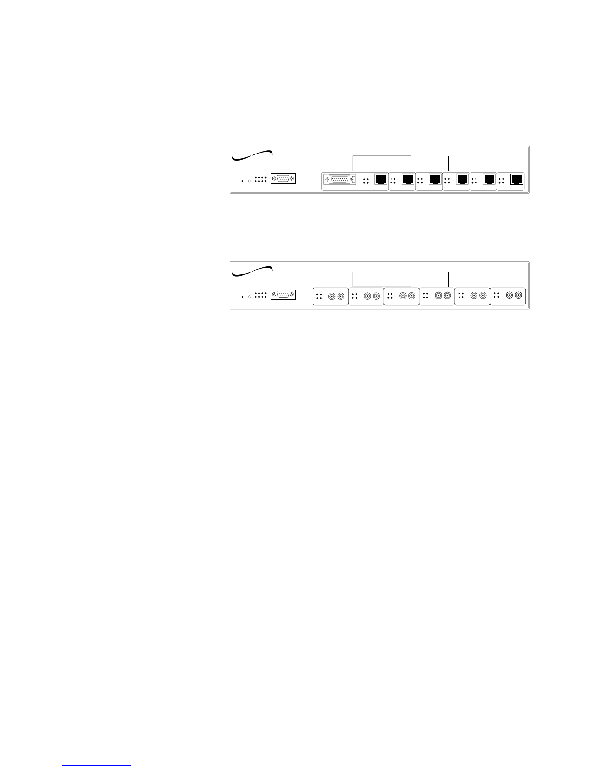
The SwitchMaster™ Eight Segment Bridge is a multi-segment Ethernet
bridge that provides six RJ-45 ports (with one alternate AUI connector)
with installation space for two additional X Slot multi-media connections.
The SwitchMasterFL™ Eight Segment Bridge is a multi-segment Ethernet
bridge that provides six (6) pairs of fiber transmit (TX) and receive (RX)
data connectors with installation space for two additional X Slot multimedia connections.
As shipped, either the SwitchMaster™ or the SwitchMasterFL™ Eight
Segment Bridge is a fully functional bridge that can be used for connecting
and/or for isolating Ethernet networks. Bridge ports can be set individually
to full or half duplex.
The optional X Slot cards , if installed, provide either an AUI transceiver
network connection or an RJ-45 connection to 10BaseT and/or an RJ-45
connection to 100BaseTX.
1-1
Status
Power
X Slot 2
™
Eight Segment Bridge
Serial
Reset
X Slot 1
networks
TRANSITION
SwitchMaster
Segment 1 Segment 2
Segment 3 Segment 4 Segment 5
Segment 6
AUI
RX
COL
LINK
TX
RX
COL
LINK
TX
RX
COL
LINK
TX
RX
COL
LINK
TX
RX
COL
LINK
TX
RX
COL
LINK
TX
SwitchMaster FL
Status
RX
COL
LINK
TX
RX TX
Segment 1
Power
X Slot 2
™
Eight Segment Bridge
Serial
Reset
X Slot 1
networks
TRANSITION
RX
RX
COL
LINK
TX
RX TX
Segment 2
RX
COL
LINK
TX
RX TX
Segment 3
RX
COL
LINK
TX
RX TX
Segment 4
RX
COL
LINK
TX
RX TX
Segment 5
RX
COL
LINK
TX
RX TX
Segment 6
Page 8
SwitchMaster™/SwitchMasterFL™
1.1 About Bridges
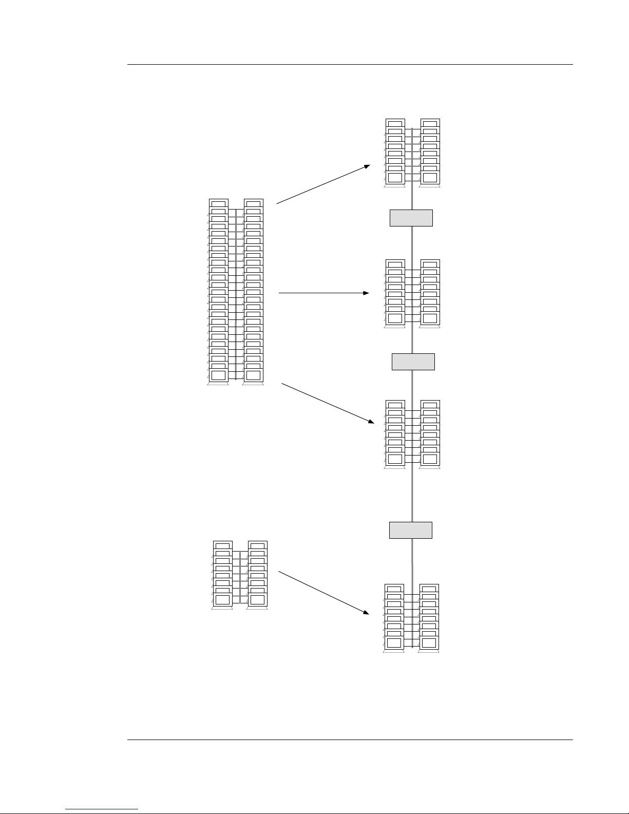
A bridge is a network device that can be used to merge two or more Local
Area Networks (LANs) into a single functional LAN or, alternatively, to
separate a single LAN into two or more functional LANs.
The bridge is used to merge two or more LANs into a single functional
LAN for:
• increasing reliable distances between stations, particularly in Ethernet
environments
• connecting different media types.
The bridge is used to separate one LAN into two or more functional LANs
for:
• increasing available bandwidth by decreasing station contention
• decreasing delays caused by multiple stations
• isolating LAN failures.
These contradictory objectives are achieved because the bridge receives
and stores data packets from all stations on attached LANs, then forwards
the data packets to all other stations on all other attached LANs. Because
the bridge forwards data packets from one LAN to another, stations on the
sending LAN can communicate with receiving stations on other LANs,
merging the LANs into one functional LAN. Because the bridge stores
received data packets, transmission of data packets from one LAN to
another is not controlled by the sending or receiving LAN, functionally
separating the LANs.
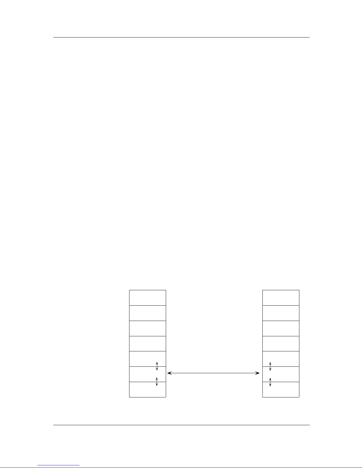
A bridge is an ISO/OSI Model Layer 2 Data Link relay. The ISO/OSI Data
Link layer transmits data packets from a source across a link to a peer
destination. The data link layer transmits data across the link by
interfacing with the physical layer (the transmission line and connectors)
at each end of the link.
1-2
LAYER 7
LAYER 6
LAYER 5
LAYER 4
LAYER 3
LAYER 2
LAYER 1
Data Link
Network
Physical
LAYER 7
LAYER 6
LAYER 5
LAYER 4
LAYER 3
LAYER 2
LAYER 1
Data Link
Network
Physical
BRIDGE CONNECTION
Page 9
EIGHT SEGMENT BRIDGE
1. INTRODUCTION
1-3
Remote, unattached LAN
Large, slow LAN
Smaller, faster LAN #2
BRIDGE #1
Smaller, faster LAN #3
Smaller, faster LAN #1
Attached LAN
BRIDGE #2
BRIDGE #3
Page 10

SwitchMaster™/SwitchMasterFL™
According to the IEEE 802.1d specification, bridges must:
• Store and Forward
• Learn Addresses
• Age Addresses
• Participate in “Spanning Tree”
Store and Forward
A data packet sent out on a LAN is received by the bridge, which stores
the data packet exactly as received. Later, when there is no traffic on the
LAN, the bridge sends the data packet out, either on the destination LAN
or on all LANs other than the LAN on which the data packet was received.
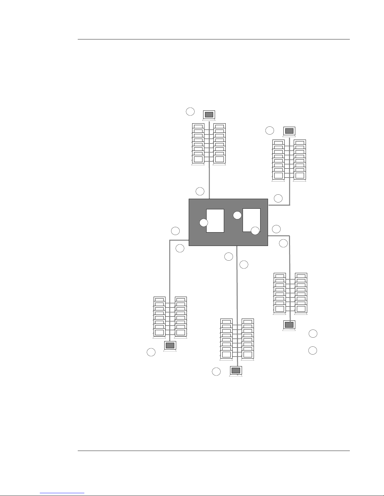
A possible sequence of events is:
1. Source #1 sends data packet intended for destination #1.
2. Bridge copies data packet #1 and waits.
3. Source #2 sends data packet intended for destination #2.
4. Bridge copies data packet #2 and waits.
5. Source #3 sends data packet intended for destination #3 on same
LAN.
6. Destination #3 receives data packet #3.
7. Bridge discards (filters) data packet #3.
8. Bridge sends data packet #1 for unknown destination #1 over all
LANs except LAN from which data packet # was received.
9. Bridge sends data packet #2 for unknown destination #2 over all
LANs except LAN from which data packet #2 was received.
10. Destination #1 receives data packet #1.
11. Destination #2 receives data packet #2.
1-4
Page 11
1. INTRODUCTION
1-5
EIGHT SEGMENT BRIDGE
Destination #2
Destination #1
Source #2
1
Source #1
Packet #1
Packet #1
Bridge
Source #3
Destination #3
5
3
2
4
6
11
10
9
78
8
8
8
9
9
9
Page 12

SwitchMaster™/SwitchMasterFL™
Learn Addresses
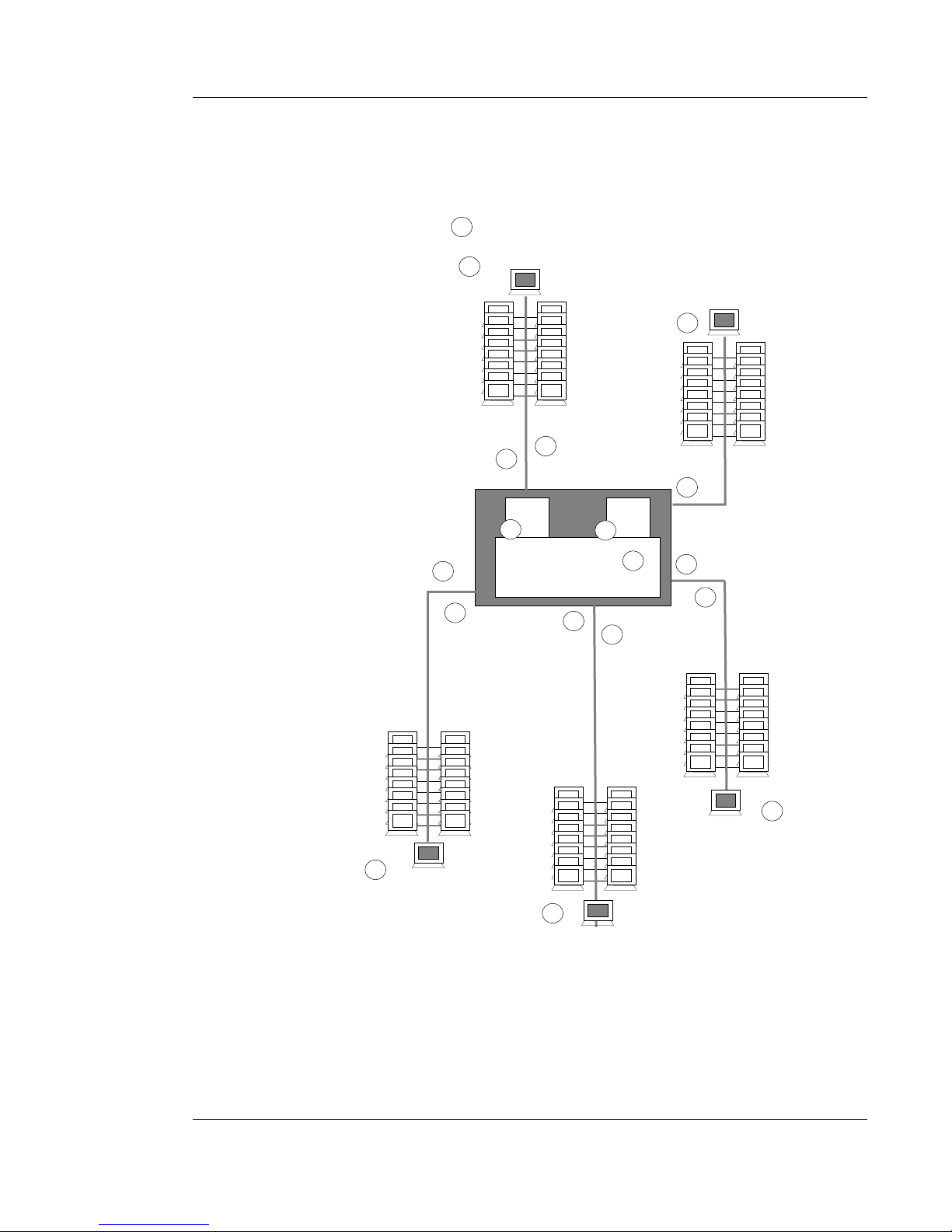
When a data packet is received by the bridge, the source identifier and
LAN are copied from the packet header and stored in the address cache.
Then, when later packets are received, the bridge compares the
destination identifier of the received packet with cache addresses. If a
match is found, the bridge “knows” the destination LAN and sends the
data packet out only on the known destination LAN.
A possible sequence of events is:
1. Source #1 sends data packet intended for destination #1.
2. Bridge copies data packet #1 with source identifier and LAN into
cache, then waits.
3. Source #2 sends data packet intended for destination #2.
4. Bridge copies data packet #2 with source identifier and LAN into
cache, then waits.
5. Source #3 sends data packet intended for destination #3.
6. Bridge copies data packet #3 with source identifier and LAN into
cache, then “knows” destination #3 as source #1.
7. Bridge sends data packet #1 for unknown destination #1 over all
LANs except LAN from which data packet #1 was received.
8. Bridge sends data packet #2 for unknown destination #2 over all
LANs except LAN from which data packet #2 was received.
9. Bridge sends data packet #3 for destination #3 (also source #1)
over destination #3 /source #1 LAN.
10. Destination #1 receives data packet #1.
11. Destination #2 receives data packet #2.
12. Destination #3 receives data packet #3.
1-6
Page 13
1. INTRODUCTION
1-7
EIGHT SEGMENT BRIDGE
Bridge
Destination #2
Destination #1
Source #2
Source #1
Source #3
Destination #2
1
5
3
11
7
8
9
7
7
7
12
10
8
8
8
Packet #1
Packet #1
Address Cache
source 1
source 2
source 3
source 4
source 5
LAN 1
LAN 2
LAN 3
LAN 4
LAN 5
2
6
4
Page 14

SwitchMaster™/SwitchMasterFL™
Age Addresses
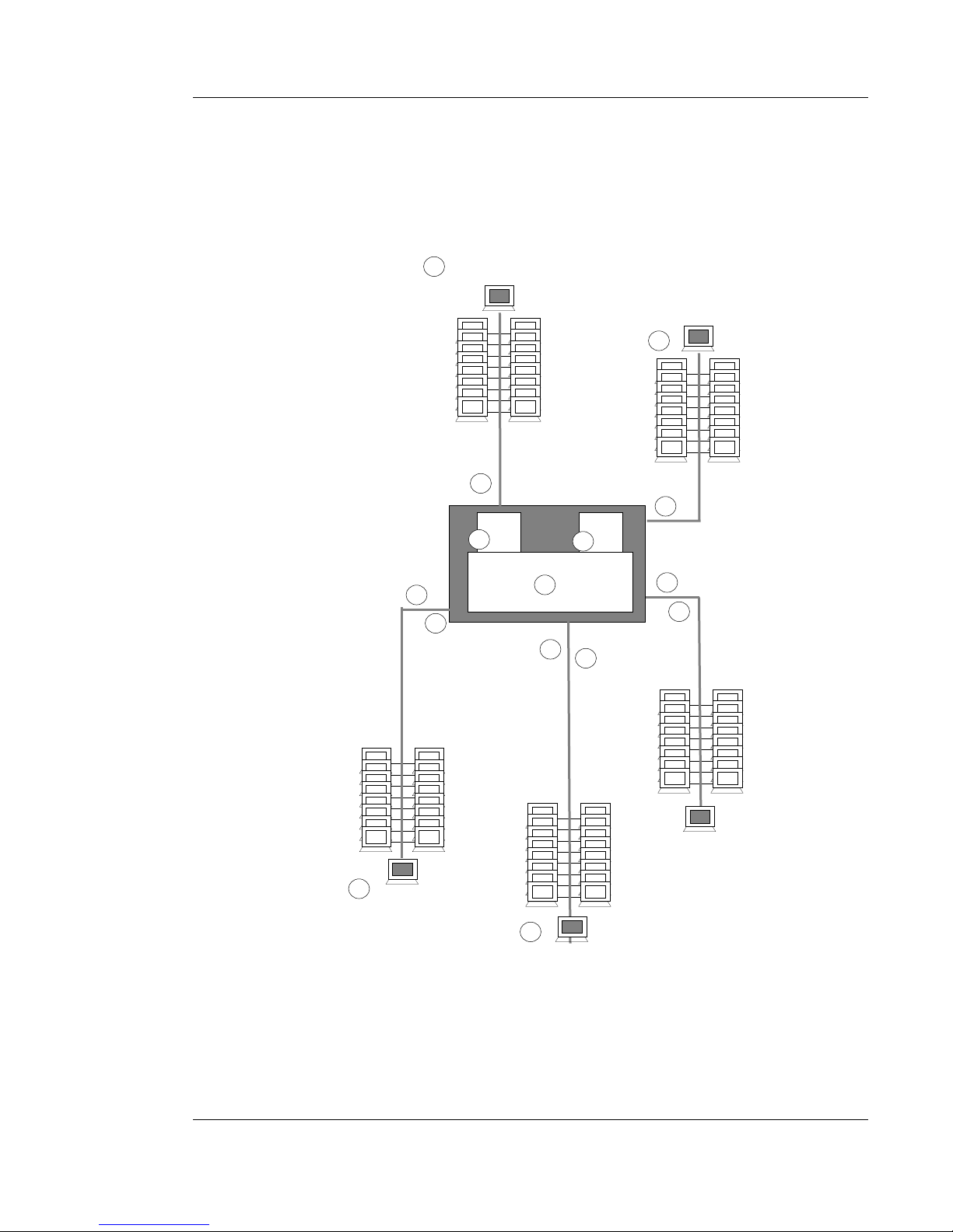
When a data source identifier is copied from a packet header into the
address cache, the bridge compares the destination identifier of the
received packet with cache addresses. If a match is found, the bridge
“knows” the destination LAN and sends the data packet only on the
known destination LAN. LANs which neither send nor receive data
packets for a defined period of time are “aged”, or eliminated from cache
memory.
A possible sequence of events, as shown, is:
1. Source #1 sends data packet intended for destination #1.
2. Bridge copies data packet #1 with source identifier and LAN into
cache.
3. Bridge deletes oldest source identifier #2 and LAN from cache,
then waits.
4. Source #2 sends data packet intended for destination #2.
5. Bridge copies data packet #2 with newest source identifier and
LAN into cache.
6. Bridge sends data packet #1 for unknown destination #1 over all
LANs except LAN from which data packet #1 was received.
7. Bridge sends data packet #2 for unknown destination #2 over all
LANs except LAN from which data packet #2 was received.
8. Destination #1 receives data packet #1.
9. Destination #2 receives data packet #2.
1-8
Page 15
1. INTRODUCTION
1-9
EIGHT SEGMENT BRIDGE
Bridge
Destination #1
Source #2
Source #1
Packet #1
Packet #1
Address Cache
Source #3
Destination #2
1
3
2
4
6
7
8
9
7
source 1
source 2
source 3
source 4
source 5
LAN 1
LAN 2
LAN 3
LAN 4
LAN 5
5
6
6
6
7
7
Page 16

SwitchMaster™/SwitchMasterFL™
1-10
Participate In “Spanning Tree”
The spanning tree algorithm is intended to prevent LAN failure caused by
the unintended generation of infinite broadcast loops.
Infinite Loops
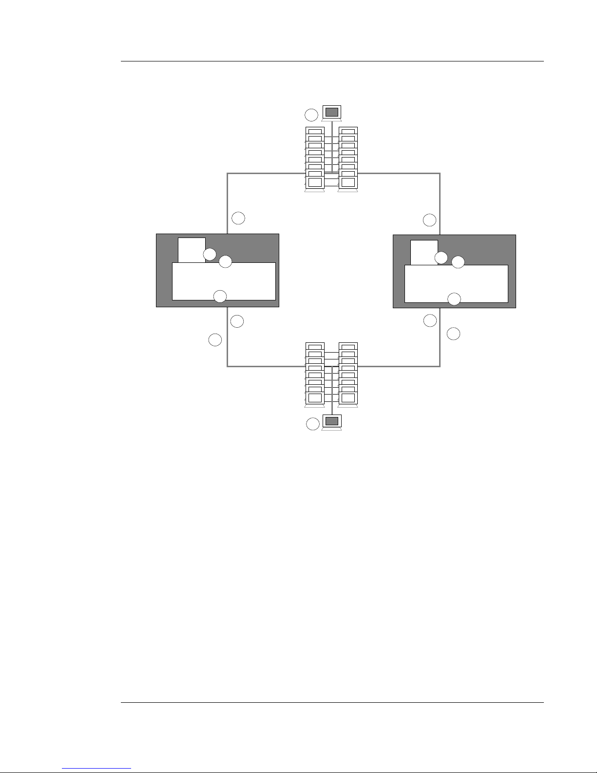
Since bridges forward data packets across all LANs except the LAN from
which the data packet is received, and since bridges are transparent to all
other bridges, when multiple bridges connect multiple LANs, infinite
loops can be generated by situations such as the following:
1. Source #1 sends data packet intended for destination #1 on LAN
#1.
2. Bridge #1 and Bridge #2 copy data packet #1, with LAN #1
identifier, into cache.
3. Randomly, Bridge #1 responds before Bridge #2. Bridge #1 sends
data packet #1 out onto LAN #2.
4. Destination #1 receives data packet #1.
5. Bridge #2 sends data packet #1 on LAN #2.
6. Bridge #2 receives data packet #1 on LAN #2 and copies data
packet #1, with LAN #2 identifier, into cache.
7. Bridge #1 receives data packet #1on LAN #2 and copies data
packet #1, with LAN #2 identifier, into cache.
8. Bridge #2 sends data packet #1 on LAN #1.
9. Bridge #1 sends data packet #1 on LAN #1.
10. Bridge #2 receives data packet #1 on LAN #1 and copies data
packet #1, with LAN #1 identifier, into cache.
11. Bridge #1 receives data packet #1on LAN #1 and copies data
packet #1, with LAN #1 identifier, into cache.
12. Bridge #1 sends data packet #1 out on LAN #2.
13. Bridge #2 sends data packet #1 on LAN #2.
AND SO ON. . . .
Page 17
1. INTRODUCTION
1-11
EIGHT SEGMENT BRIDGE
The “Spanning Tree” Algorithm
The “Spanning Tree” algorithm avoids the generation of infinite loops by
dynamically defining one and only one direct logical path between any
two bridged LANs.
The spanning tree algorithm uses the fields:
root identifier
cost to root
transmitter
to dynamically identify one “root” bridge for each network and one
designated LAN bridge for each LAN on the network.
LAN #2
Destination #1
LAN #1
Source #1
1
4
Bridge #1
Bridge #2
Packet #1
Address Cache
source 1
source 1
source 1
source 1
LAN 1
LAN 2
LAN 1
LAN 2
Packet #1
Address Cache
source 1
source 1
source 1
source 1
LAN 1
LAN 2
LAN 1
LAN 2
9
2
7
12
5
3
2
6
11
10
8
13
Page 18
1.2 The SwitchMaster™ Eight Segment Bridge
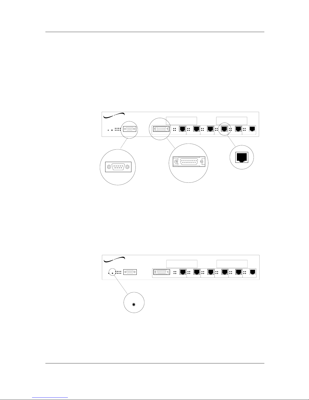
The SwitchMaster™ Eight Segment Bridge provides six RJ-45 port
connectors (with one alternate AUI connector), a DB9 serial port
connector, LED status indicators, and a reset switch.
Connectors
Six (6) RJ-45 connectors, a DB9 serial port connector, and an AUI port
connector are provided at the front of the SwitchMaster™ Eight Segment
Bridge.
Two additional spaces are provided at the front of the SwitchMaster™
Eight Segment Bridge for installation of “X” Slot cards.
NOTE: A power connector is provided at the back of the SwitchMaster™
Bridge.
Switches
The reset switch reinitializes the SwitchMaster™ Eight Segment Bridge.
1-12
SwitchMaster™/SwitchMasterFL™
TM
SwitchMaster
Eight Segment Bridge
Reset
Power
Status
Serial
Segment 1 Segment 2
Segment 3 Segment 4 Segment 5
Segment 6
RX RX
RX
RX RX
RX
TX
TX
TX TX
TX
TX
COL
LINK
COL
LINK
COL
LINK
COL
LINK
COL
LINK
COL
LINK
X Slot 2 X Slot 1
AUI
AUI
Serial
networks
TRANSITION
TM
SwitchMaster
Eight Segment Bridge
Reset
Power
Status
Serial
Segment 1 Segment 2
Segment 3 Segment 4 Segment 5
Segment 6
RX RX
RX
RX RX
RX
TX
TX
TX TX
TX
TX
COL
LINK
COL
LINK
COL
LINK
COL
LINK
COL
LINK
COL
LINK
X Slot 2 X Slot 1
AUI
Reset
networks
TRANSITION
Page 19
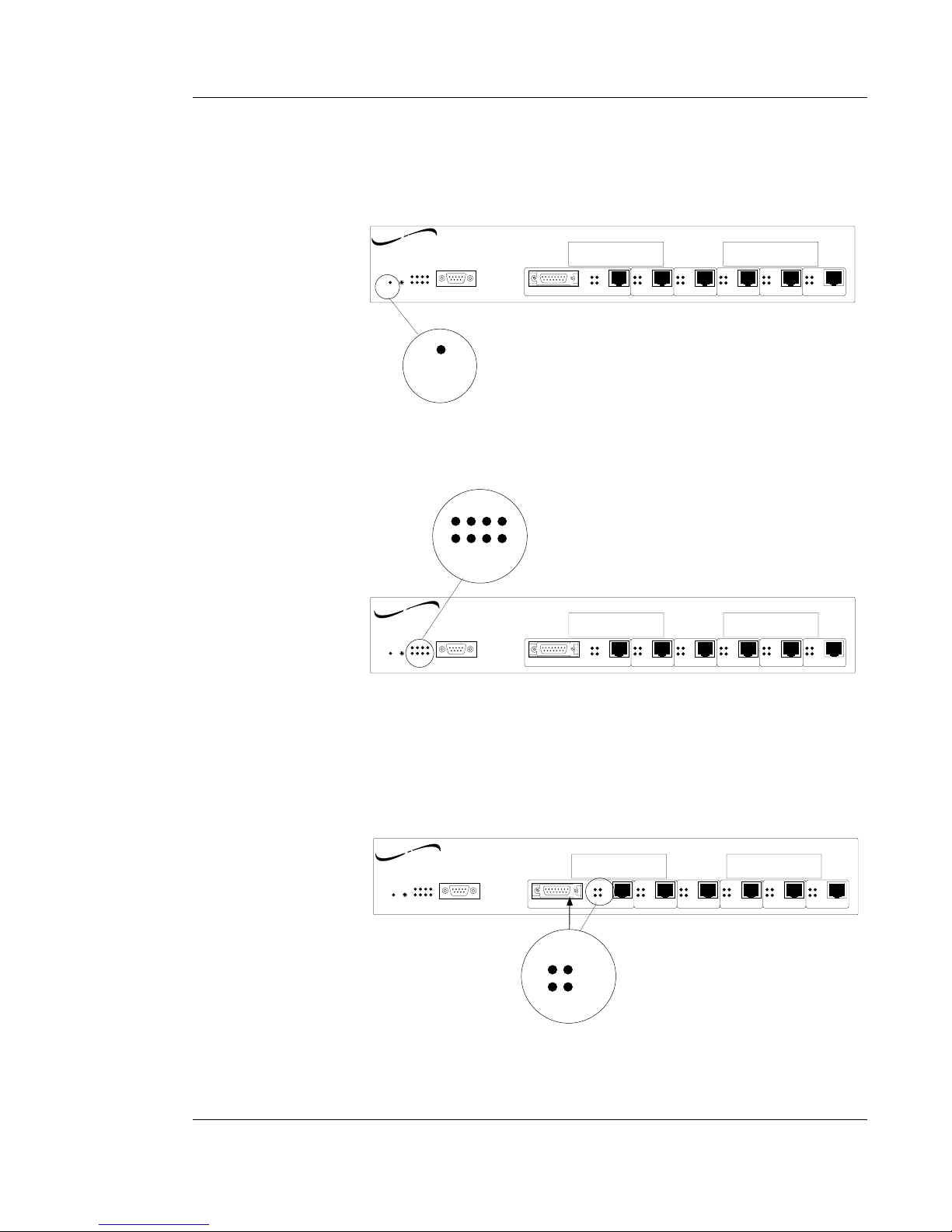
Indicators
SWITCHMASTER™ POWER INDICATOR
When the SwitchMaster Eight Segment Bridge is powered, the Power
indicator is illuminated.
SWITCHMASTER™ STATUS INDICATORS
When the SwitchMaster™ Eight Segment Bridge is functioning normally,
the eight Status indicators cycle in a steady roll.
NOTE: During power on, the eight Status indicators cycle through a
predefined diagnostic pattern.
SEGMENT 1 AUI STATUS INDICATORS
WhenSegment 1 is connected through the AUI connector, the Segment 1
status LEDs indicate AUI network activity.
1. INTRODUCTION
1-13
EIGHT SEGMENT BRIDGE
TM
SwitchMaster
Eight Segment Bridge
Reset
Power
Status
Serial
Segment 1 Segment 2
Segment 3 Segment 4 Segment 5
Segment 6
RX RX
RX
RX RX
RX
TX
TX
TX TX
TX
TX
COL
LINK
COL
LINK
COL
LINK
COL
LINK
COL
LINK
COL
LINK
X Slot 2 X Slot 1
AUI
Status
networks
TRANSITION
TM
SwitchMaster
Eight Segment Bridge
Reset
Power
Status
Serial
Segment 1 Segment 2
Segment 3 Segment 4 Segment 5
Segment 6
RX RX
RX
RX RX
RX
TX
TX
TX TX
TX
TX
COL
LINK
COL
LINK
COL
LINK
COL
LINK
COL
LINK
COL
LINK
X Slot 2 X Slot 1
AUI
RX
TX
COL
LINK
networks
TRANSITION
TM
SwitchMaster
Eight Segment Bridge
Reset
Power
Status
Serial
Segment 1 Segment 2
Segment 3 Segment 4 Segment 5
Segment 6
RX RX
RX
RX RX
RX
TX
TX
TX TX
TX
TX
COL
LINK
COL
LINK
COL
LINK
COL
LINK
COL
LINK
COL
LINK
X Slot 2 X Slot 1
AUI
Power
networks
TRANSITION
Page 20
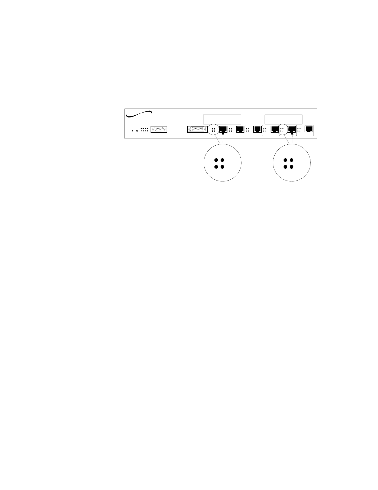
SEGMENT 1 RJ-45 STATUS INDICATORS
WhenSegment 1 is connected through the RJ-45 connector, the Segment 1
status LEDs indicate RJ-45 connection status.
SEGMENT 2-SEGMENT 6 RJ-45 STATUS INDICATORS
When Segment 2 through Segment 6 RJ-45 are connected, the Segment
status LEDs indicate RJ-45 connection status.
1-14
SwitchMaster™/SwitchMasterFL™
TM
SwitchMaster
Eight Segment Bridge
Reset
Power
Status
Serial
Segment 1 Segment 2
Segment 3 Segment 4 Segment 5
Segment 6
RX RX
RX
RX RX
RX
TX
TX
TX TX
TX
TX
COL
LINK
COL
LINK
COL
LINK
COL
LINK
COL
LINK
COL
LINK
X Slot 2 X Slot 1
AUI
RX
TX
COL
LINK
networks
TRANSITION
RX
TX
COL
LINK
Page 21
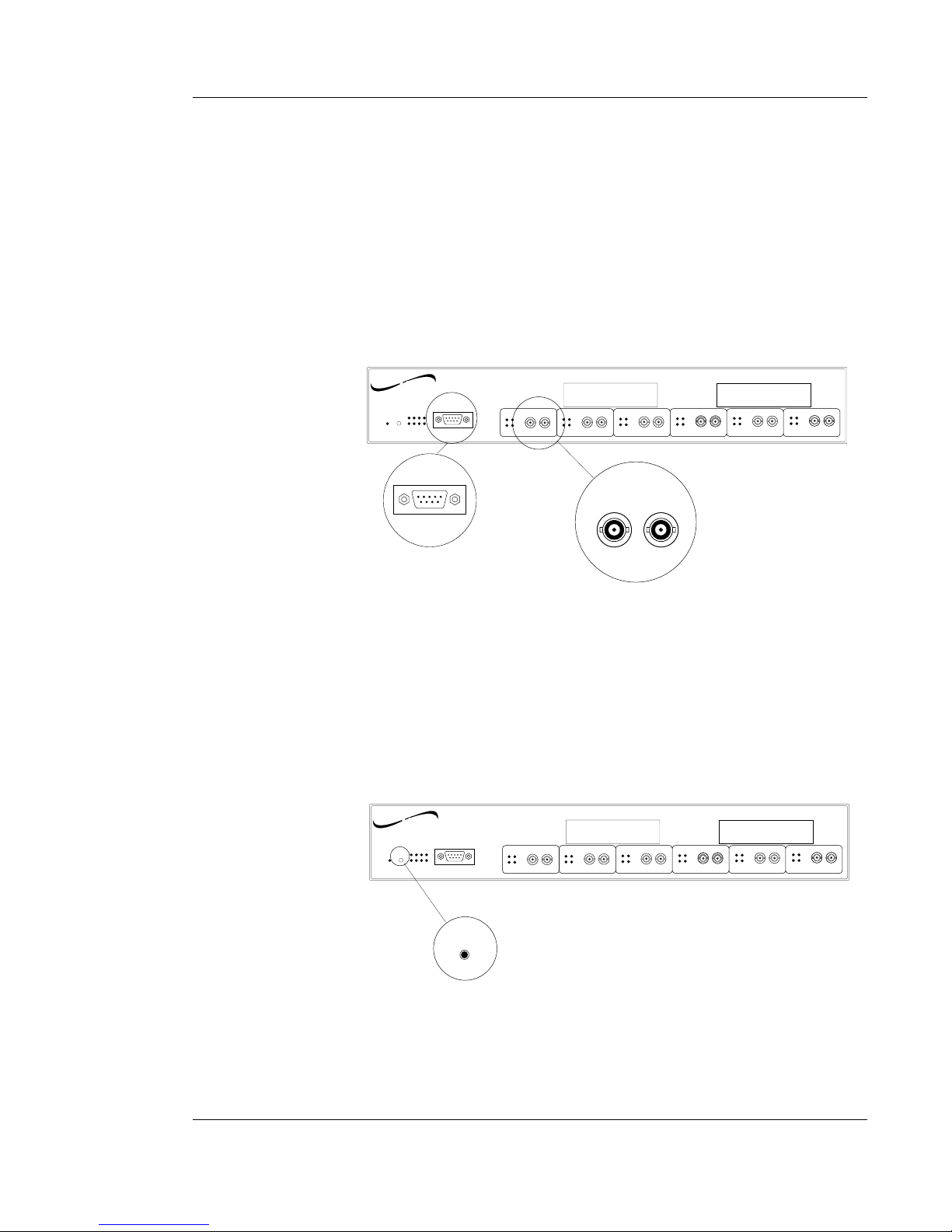
1. INTRODUCTION
1-15
EIGHT SEGMENT BRIDGE
1.3 The SwitchMasterFL™ Eight Segment Bridge
The SwitchMasterFL™ Eight Segment Bridge provides six (6) pairs of fiber
transmit (TX) and receive (RX) data connectors, a DB9 serial port
connector, LED status indicators, and a reset switch.
Connectors
Six (6) sets of fiber (TX and RX) connectors and a DB9 serial port
connector are provided at the front of the SwitchMasterFL™ Eight Segment
Bridge.
Two additional spaces are provided at the front of the SwitchMasterFL™
Eight Segment Bridge for installation of “X” Slot cards.
NOTE: A power connector is provided at the back of the
SwitchMasterFL™ Bridge.
Switches
The reset switch reinitializes the SwitchMasterFL™ Eight Segment Bridge.
SwitchMaster FL
Status
RX
COL
LINK
TX
RX TX
Segment 1
Power
X Slot 2
™
Eight Segment Bridge
Serial
Reset
X Slot 1
networks
TRANSITION
RX
RX
COL
LINK
TX
RX TX
Segment 2
RX
COL
LINK
TX
RX TX
Segment 3
RX
COL
LINK
TX
RX TX
Segment 4
RX
COL
LINK
TX
RX TX
Segment 5
RX
COL
LINK
TX
RX TX
Segment 6
RX TX
Serial
SwitchMaster FL
Status
RX
COL
LINK
TX
RX TX
Segment 1
Power
X Slot 2
™
Eight Segment Bridge
Serial
Reset
X Slot 1
networks
TRANSITION
RX
RX
COL
LINK
TX
RX TX
Segment 2
RX
COL
LINK
TX
RX TX
Segment 3
RX
COL
LINK
TX
RX TX
Segment 4
RX
COL
LINK
TX
RX TX
Segment 5
RX
COL
LINK
TX
RX TX
Segment 6
Reset
Page 22
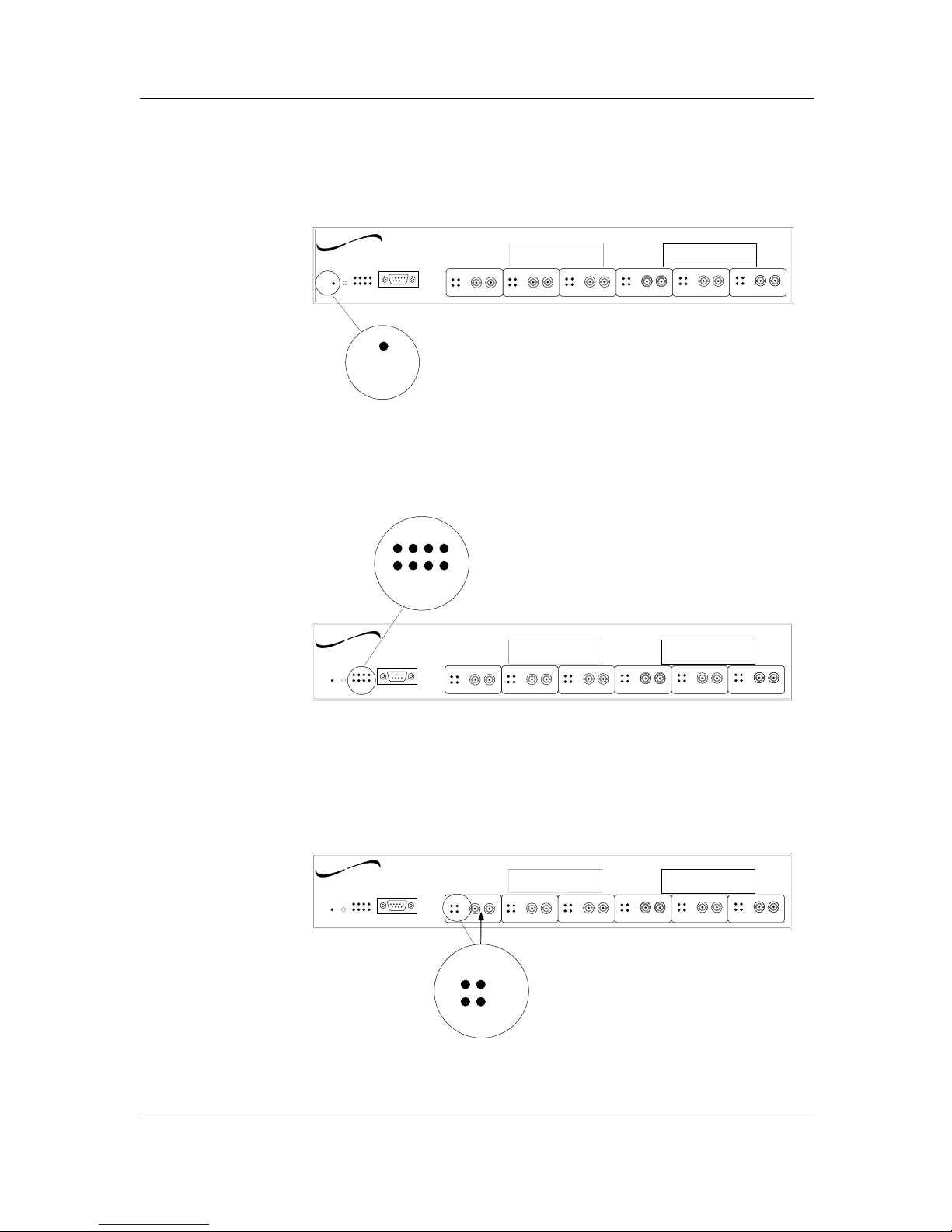
Indicators
SWITCHMASTER™ POWER INDICATOR
When the SwitchMasterFL™ Eight Segment Bridge is powered, the Power
indicator is illuminated.
SWITCHMASTER™ STATUS INDICATORS
When the SwitchMasterFL™ Eight Segment Bridge is functioning
normally, the eight Status indicators cycle in a steady roll.
NOTE: During power on, the eight Status indicators cycle through a
predefined diagnostic pattern.
SEGMENT 1-SEGMENT 6 STATUS INDICATORS
When Segment 2 through Segment 6 RJ-45 are connected, the Segment
status LEDs indicate RJ-45 connection status.
1-16
SwitchMaster™/SwitchMasterFL™
SwitchMaster FL
Status
RX
COL
LINK
TX
RX TX
Segment 1
Power
X Slot 2
™
Eight Segment Bridge
Serial
Reset
X Slot 1
networks
TRANSITION
RX
RX
COL
LINK
TX
RX TX
Segment 2
RX
COL
LINK
TX
RX TX
Segment 3
RX
COL
LINK
TX
RX TX
Segment 4
RX
COL
LINK
TX
RX TX
Segment 5
RX
COL
LINK
TX
RX TX
Segment 6
Power
SwitchMaster FL
Status
RX
COL
LINK
TX
RX TX
Segment 1
Power
X Slot 2
™
Eight Segment Bridge
Serial
Reset
X Slot 1
networks
TRANSITION
RX
RX
COL
LINK
TX
RX TX
Segment 2
RX
COL
LINK
TX
RX TX
Segment 3
RX
COL
LINK
TX
RX TX
Segment 4
RX
COL
LINK
TX
RX TX
Segment 5
RX
COL
LINK
TX
RX TX
Segment 6
Status
SwitchMaster FL
Status
RX
COL
LINK
TX
RX TX
Segment 1
Power
X Slot 2
™
Eight Segment Bridge
Serial
Reset
X Slot 1
networks
TRANSITION
RX
RX
COL
LINK
TX
RX TX
Segment 2
RX
COL
LINK
TX
RX TX
Segment 3
RX
COL
LINK
TX
RX TX
Segment 4
RX
COL
LINK
TX
RX TX
Segment 5
RX
COL
LINK
TX
RX TX
Segment 6
RX
TX
COL
LINK
Page 23
1. INTRODUCTION
1-17
EIGHT SEGMENT BRIDGE
1.4 SwitchMaster™ Bridge X Slot Cards
X Slot Cards allow the SwitchMaster™ Bridge to provide additional
segments, including wide area network (WAN) connections.
NOTE: X Slot cards can be installed in the field.
Full Duplex Ethernet X Slot Card
The Full Duplex Ethernet X Slot Card, which provides the functionality of
a redundant Segment 1, is installed at either of the two SwitchMaster™
Bridge X Slot locations.
Connectors
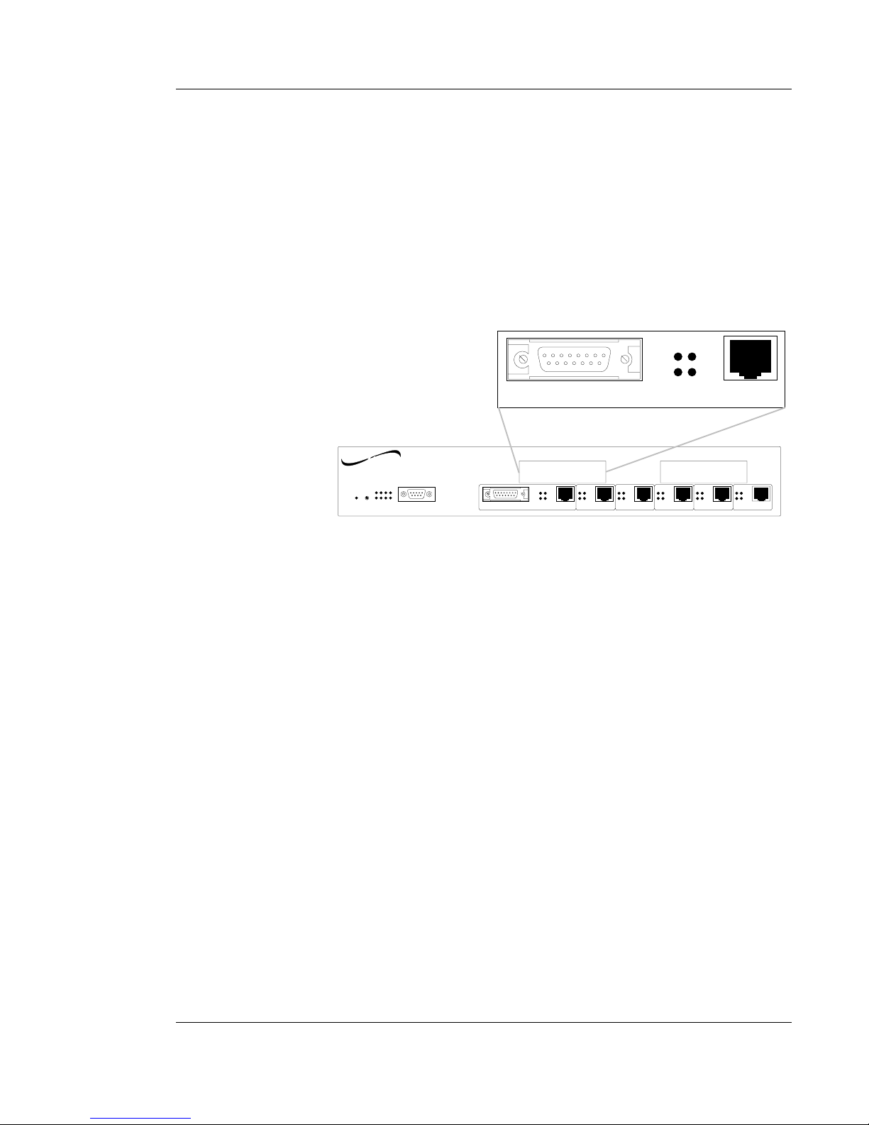
One (1) RJ-45 connector, and one (1) AUI port connector are provided at
the front of the installed Full Duplex Ethernet X Slot Card.
Indicators
When the RJ-45 is connected and the SwitchMaster™ is powered, the Full
Duplex Ethernet X Slot Card status LEDs indicate the RJ-45 connection
status.
When the AUI is connected, the Full Duplex Ethernet X Slot Card status
LEDs indicate AUI network activity.
When the connection over the media is good, the LINK status LED
is illuminated.
When the link is transmitting data, the TX (transmit) status LED is
illuminated.
When the link is receiving data, the RX (receive) status LED is
illuminated.
AUI
RX
COL
LINK
TX
TM
SwitchMaster
Eight Segment Bridge
Reset
Power
Status
Serial
Segment 1 Segment 2
Segment 3 Segment 4 Segment 5
Segment 6
RX RX
RX
RX RX
RX
TX
TX
TX TX
TX
TX
COL
LINK
COL
LINK
COL
LINK
COL
LINK
COL
LINK
COL
LINK
X Slot 2 X Slot 1
AUI
networks
TRANSITION
Page 24
1-18
SwitchMaster™/SwitchMasterFL™
100BaseT X Slot Card
The 100BaseT Slot Card, which provides connection to 100BaseT media,
is installed at either of the two SwitchMaster™ Bridge X Slot locations.
Connectors
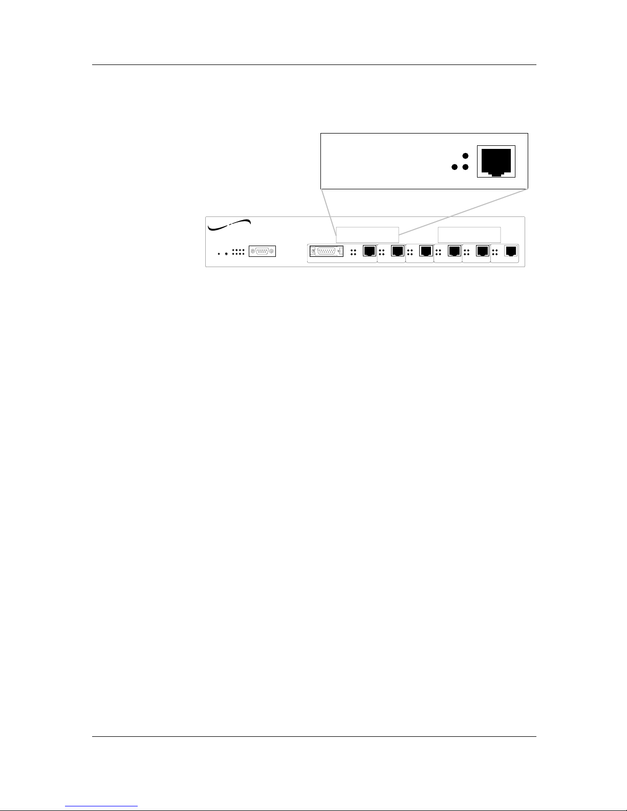
One (1) RJ-45 connector is provided at the front of the installed 100BaseT
X Slot Card.
Indicators
When the RJ-45 is connected and the SwitchMaster™ is powered, the
100BaseT X Slot Card status LEDs indicate the RJ-45 connection status.
When the connection over 100BaseT media is good, the
100BaseT X Slot Card LINK status LED is illuminated.
When the 100BaseT link is transmitting data, the TX (transmit)
status LED is illuminated.
When the 100BaseT link is receiving data, the RX (receive) status
LED is illuminated.
TX
RX
LINK
TM
SwitchMaster
Eight Segment Bridge
Reset
Power
Status
Serial
Segment 1 Segment 2
Segment 3 Segment 4 Segment 5
Segment 6
RX RX
RX
RX RX
RX
TX
TX
TX TX
TX
TX
COL
LINK
COL
LINK
COL
LINK
COL
LINK
COL
LINK
COL
LINK
X Slot 2 X Slot 1
AUI
networks
TRANSITION
Page 25

2-1
EIGHT SEGMENT BRIDGE
2. SITE PLANNING
Site planning for the SwitchMaster Eight Segment Bridge requires
consideration both of site conditions and of the Ethernet IEEE 802.3
standards to which the SwitchMaster Bridge conforms.
2.1 Site Considerations
The site for the SwitchMaster Bridge must provide the following:
• AC power outlet for each SwitchMaster Bridge Unit
• Adequate ventilation
• Standard environmental conditions
• Isolation from electrical noise, including radio transmitters and
broadbank amplifiers, motors, high power electrical lines, or
fluorescent light fixtures
Additionally:
• The twisted pair cables should not run in the same conduit with
power line cables.
• Phone lines should be separated from data cables.
• Flat or “silver satin” wires should not be used.
2.2 Ethernet Network Considerations
NOTE: A segment is the cable connection, including connectors, between
cable interfaces in an Ethernet LAN.
For 10BaseT and mixed media networks containing 10BaseT segments:
• Repeater sets are required for all segment interconnections
• A Media Access Unit (MAU) is part of the repeater set and counts
toward the maximum number of transceiver devices on a segment
• The transmission path between any data source and destination can
consist of no more than five segments.
Page 26

Page 27

3-1
EIGHT SEGMENT BRIDGE
3. INSTALLATION
The SwitchMaster™ Eight Segment Bridge can be installed as a passive
plug-and-play device. .
To install the SwitchMaster™ Bridge:
• Unpack the SwitchMaster™ Bridge
• Install in rack or on table
• Connect to network
• Connect to power.
Direction is provided in the pages that follow.
3.1 Unpacking the SwitchMaster™ Bridge
Use the following packing contents lists to verify the shipment.
Item Part Number
SwitchMaster™ Bridge MSB-E6/X2 or MSB-E6/E2
Power Cord 3344, 3347, 3348, 3349, or 3523,
(depending upon power configuration in
country where installed)
User’s Guide 7341
Additionally, the SwitchMaster™ Bridge packing contents may include the
following:
Item Part Number
Full Duplex Ethernet
X Slot Card FDE-XSLOT
100BaseTX
X Slot Card 100BTX-XSLOT
Page 28
3.2 Installing in Rack or on Table
Depending upon site conditions, the SwitchMaster™ Bridge can be
installed in a standard 19-inch rack or on an open shelf or table.
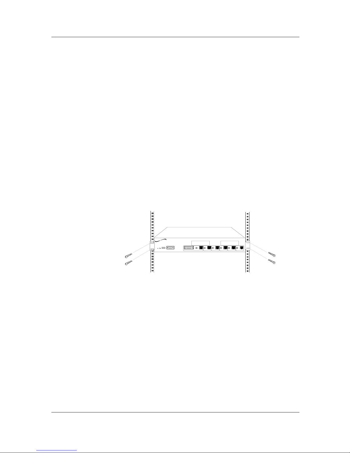
Standard 19-Inch Rack Installation
NOTE: SwitchMaster™ Bridges are shipped with attached brackets for
standard 19-inch rack installation. Rackmount screws and clip nuts are
NOT provided with the SwitchMaster™ Bridges.
To install the SwitchMaster™ Bridge in a standard 19-inch rack:
1. Locate four (4) screws (and clip nuts, if necessary) for each
SwitchMaster™ Bridge to be installed.
2. Carefully align the SwitchMaster™ Bridge between the 19-inch rack
mounting rails at the installation position.
3. Install two screws through right front bracket and two screws through
left front bracket, using clip nuts if necessary.
3-2
SwitchMaster™/SwitchMasterFL™
TM
SwitchMaster
Eight Segment Bridge
Segment 1
Segment 2
Segment 3 Segment 4 Segment 5
Segment 6
X Slot 2 X Slot 1
networks
TRANSITION
Page 29

Table-Top Installation
NOTE: SwitchMaster™ Bridges are shipped with a separate, unattached
set of adhesive-backed rubber feet for table-top installation.
CAUTION: The rubber feet MUST BE INSTALLED on the SwitchMaster™
Bridge if a SwitchMaster™ Bridge is installed on a table-top or other flat
surface. Failure to observe this caution could cause the SwitchMaster™
Bridge to overheat, resulting in data transmission failure and/or
equipment damage.
To install the SwitchMaster™ Bridge on table or other flat surface:
1. Carefully turn SwitchMaster™ Bridge to side and install four (4) rubber
feet:
• Remove protective paper from adhesive surface of rubber
foot.
• Position rubber foot at bottom corner of SwitchMaster™
Bridge
• Secure rubber foot to SwitchMaster™ Bridge.
• Repeat for remaining rubber feet.
2. Return SwitchMaster™ Bridge to upright position.
NOTE: The mounting brackets that come installed on the SwitchMaster™
Bridge can be removed and saved for later use.
3-3
EIGHT SEGMENT BRIDGE
3. INSTALLATION
Page 30
3.3 Connecting to Network
Network connections are made at:
• RJ-45 connectors
• AUI connectors
• optional X Slot Card connectors
Connecting to 10BaseT at RJ-45 Connectors
CAUTION: The RJ-45 connectors on the SwitchMaster™ Bridge are
NOT INTENDED FOR CONNECTION TO THE PUBLIC TELEPHONE
NETWORK. Failure to observe this caution could result in damage to the
public telephone network.
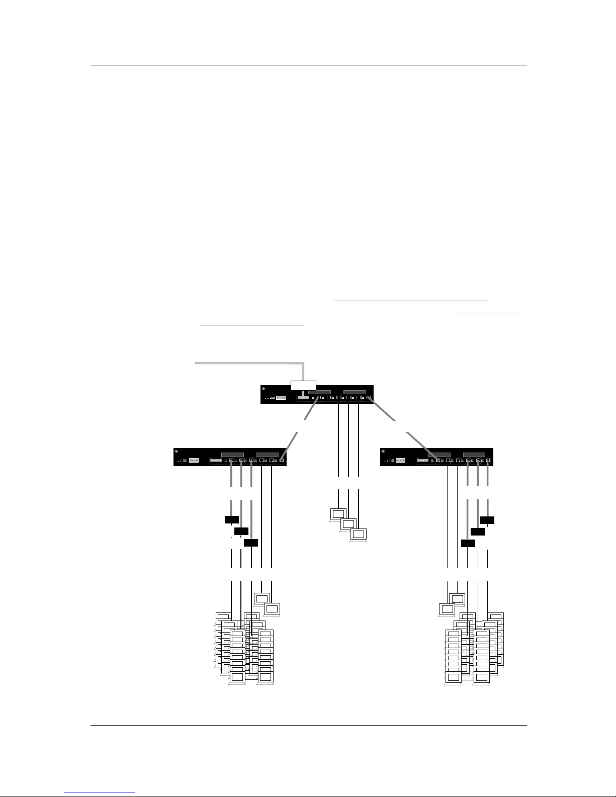
10BaseT Cable Configurations
Identify the 10BaseT network cabling requirements before connecting the
cables. 10BaseT cables for the SwitchMaster™ Bridge to terminal
must
be configured as straight through. 10BaseT cables for the SwitchMaster™
Bridge to switch or hub must be configured as crossover.
3-4
SwitchMaster™/SwitchMasterFL™
Crossover Cable
Straight Through Cable
Hub
Hub
Hub
Ethernet Network
Transceiver
Crossover Cable
Straight Through Cable
Hub
Hub
Hub
Straight Through Cable
Crossover CableCrossover Cable
Page 31
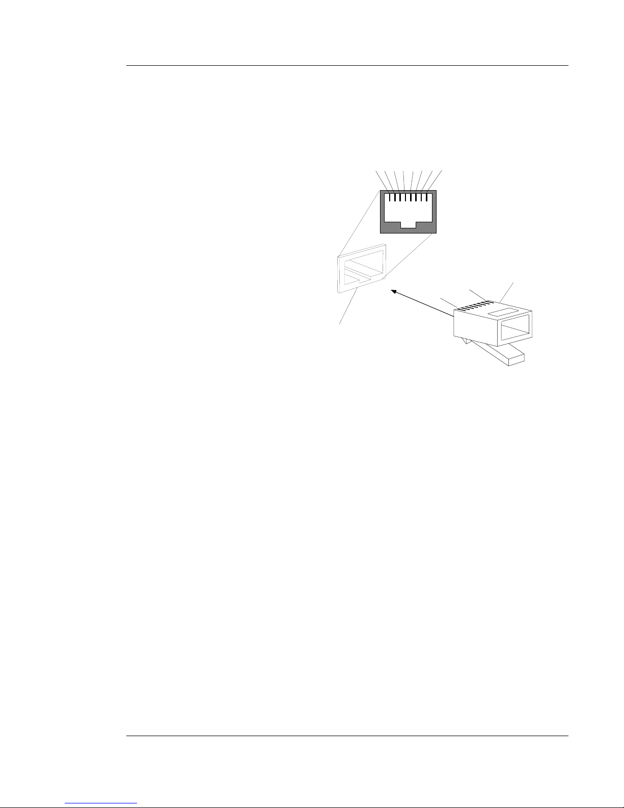
To connect RJ-45 port:
1. Locate correct cable with male RJ-45 connector at both ends.
2. Attach male RJ-45 cable connector to female RJ-45 port on
SwitchMaster™ Bridge.
3. Attach other male RJ-45 cable connector to female RJ-45 port on
terminal, hub, or other SwitchMaster™ Bridge.
1
8
RJ-45 Plug
Pin Assignments
1 2 3 4 5 6 7 8
RJ-45 Jack Pin Assignments
RJ-45 Jack
3-5
EIGHT SEGMENT BRIDGE
3. INSTALLATION
Straight Through/Crossover Pin Specifications
Straight through and crossover configurations are made at the RJ-45
connector. The two active pairs in a 10BaseT network are pins 1 & 2 and
pins 3 & 6. Use only dedicated wire pairs (such as blue/white &
white/blue, orange/white & white/orange) for the active pins.
Straight Through Cable at RJ-45 Plug
Switch Terminal
RJ-45 Male RJ-45 Male
1 . . . . . . . . . . . . . . . . . . . . . . . . 1
2 . . . . . . . . . . . . . . . . . . . . . . . 2
3 . . . . . . . . . . . . . . . . . . . . . . . 3
6 . . . . . . . . . . . . . . . . . . . . . . . . 6
Crossover Cable at RJ-45 Plug
Switch to Switch
Terminal to Terminal
RJ-45 Male RJ-45 Male
1 . . . . . . . . . . . . . . . . . . . . . . . 3
2 . . . . . . . . . . . . . . . . . . . . . . . . 6
3 . . . . . . . . . . . . . . . . . . . . . . . 1
6 . . . . . . . . . . . . . . . . . . . . . . . 2
Page 32

Connecting to Network through AUI
The AUI is connected to a transceiver which is connected to the network.
The AUI port (on Segment 1 and/or on the optional Full Duplex Ethernet X
Slot card) is always enabled.
NOTE: On the Segment 1 connection and also on the Full Duplex
Ethernet X Slot Card, only one LAN port (EITHER the AUI port OR the RJ-
45) can be used.
When connecting a transceiver to the SwitchMaster™ Bridge, the
transceiver must be configured (as when connecting to a hub or to a
repeater) with SQE OFF.
3-6
SwitchMaster™/SwitchMasterFL™
Page 33
3-7
EIGHT SEGMENT BRIDGE
3. INSTALLATION
3.4 Connecting to Power
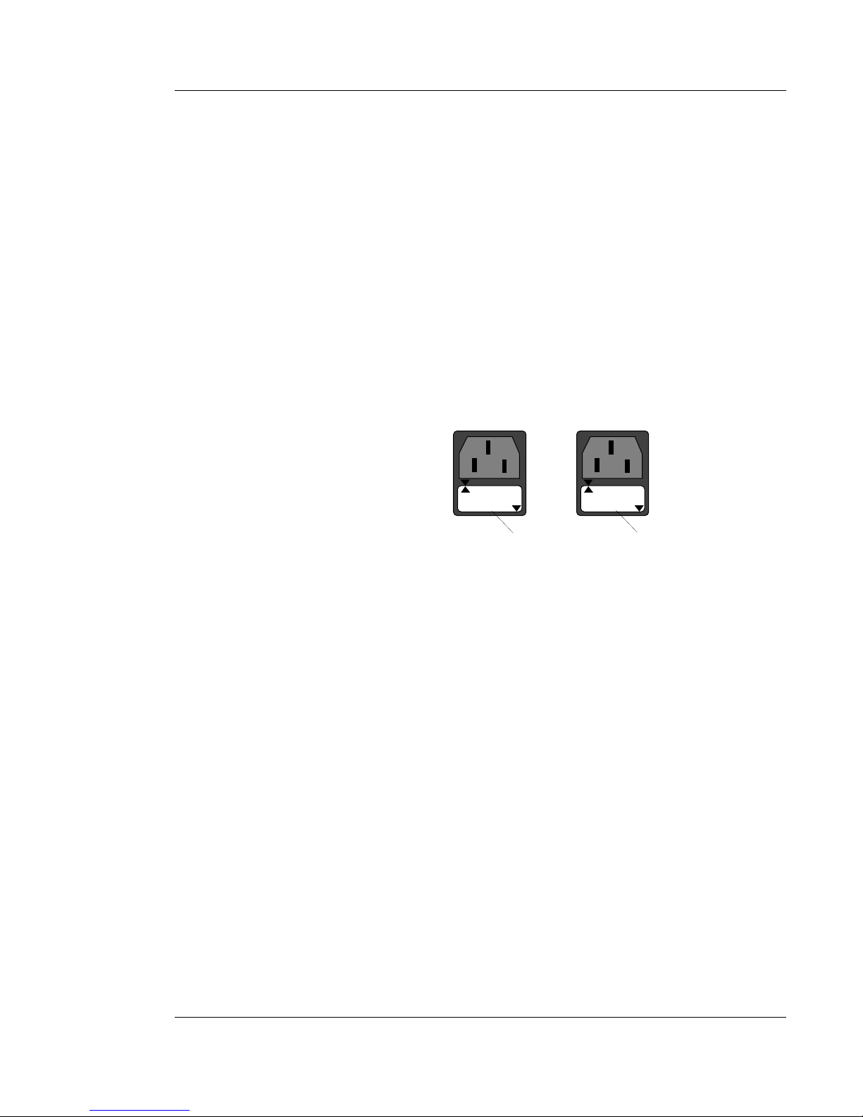
To connect the SwitchMaster™ Bridge to power:
1. At SwitchMaster™ Bridge back, locate the power receptacle and
associated fuse.
CAUTION: Fuse must be installed at correct setting for power source
voltage before connecting to AC voltage. Failure to observe this caution
could result in equipment damage.
2. Verify that the fuse is installed at the correct setting for power source
voltage.
NOTE: Installed fuse rating orientation is indicated by reading in lower
right corner of fuse holder.
If not installed at correct setting:
• Carefully open fuse receptacle, using small flat blade
screwdriver.
• Rotate fuse 180º to correct rating orientation.
• Install fuse holder in correct rating orientation.
• Close fuse receptacle.
3. Plug female unit end of power cord into SwitchMaster™ Bridge power
receptacle.
4. Plug male outlet end of power cord into correct voltage AC wall
socket.
5. At SwitchMaster™ Bridge front, verify that the POWER LED is
illuminated.
When the SwitchMaster™ Bridge is powered, Status LEDs at the
SwitchMaster™ Bridge front cycle during internal SwitchMaster™ Bridge
diagnostic testing. The Status LEDs cycle in a steady roll when the
SwitchMaster™ Bridge is fully operational.
110-120
110-120
220-240
220-240
110-120 Orientation 220-240 Orientation
Fuse Holder Fuse Holder
Page 34

Page 35
4-1
EIGHT SEGMENT BRIDGE
4. OPERATION
Operating the SwitchMaster™ Eight Segment Bridge may require:
• Power On/Power Off
• Monitoring SwitchMaster™ Bridge Operation
4.1 Power On/Power Off
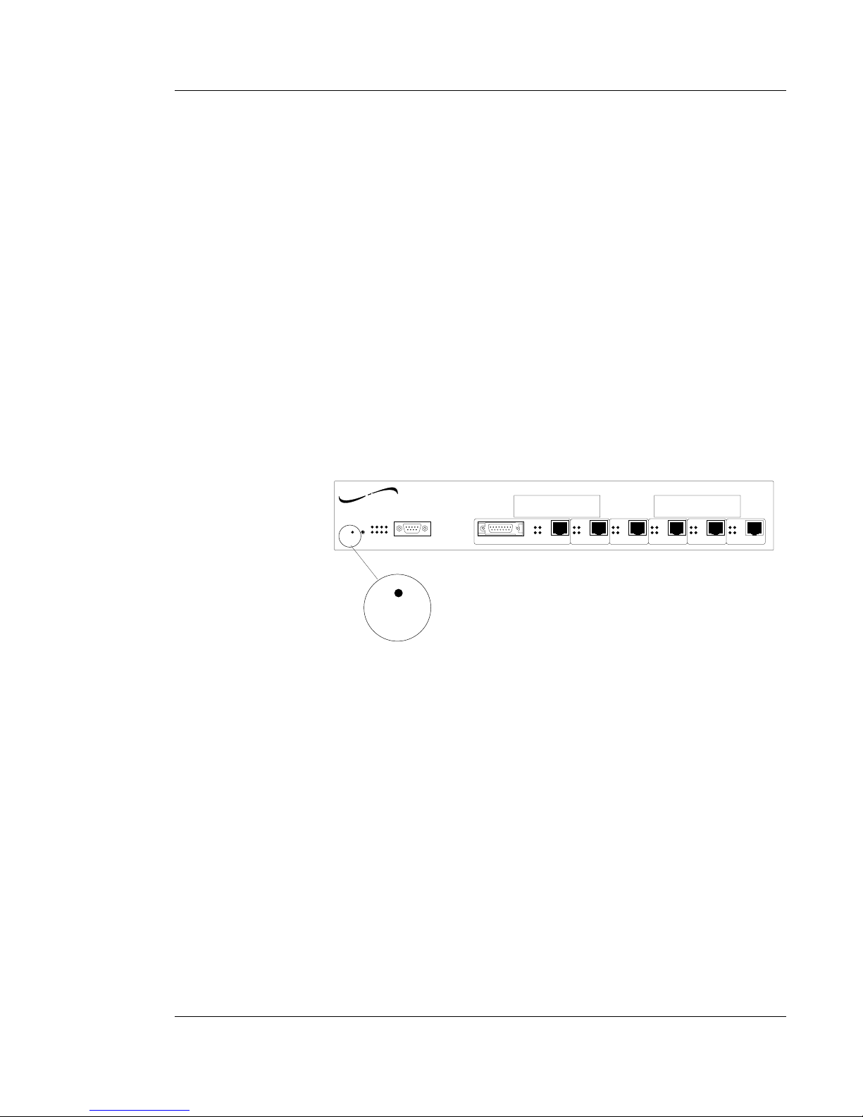
The SwitchMaster™ Eight Segment Bridge is powered ON when the power
cord is connected between the SwitchMaster™ Bridge and an AC outlet
during installation.
NOTE: When the SwitchMaster™ Eight Segment Bridge is powered, the
POWER LED on the SwitchMaster™ Bridge is illuminated.
The SwitchMaster™ Eight Segment Bridge is powered OFF when the
power cord is disconnected from the SwitchMaster™ Bridge and/or from
the AC outlet.
TM
SwitchMaster
Eight Segment Bridge
Reset
Power
Status
Serial
Segment 1 Segment 2
Segment 3 Segment 4 Segment 5
Segment 6
RX RX
RX
RX RX
RX
TX
TX
TX TX
TX
TX
COL
LINK
COL
LINK
COL
LINK
COL
LINK
COL
LINK
COL
LINK
X Slot 2 X Slot 1
AUI
Power
networks
TRANSITION
Page 36
4.2 Monitoring SwitchMaster™ Bridge Operation
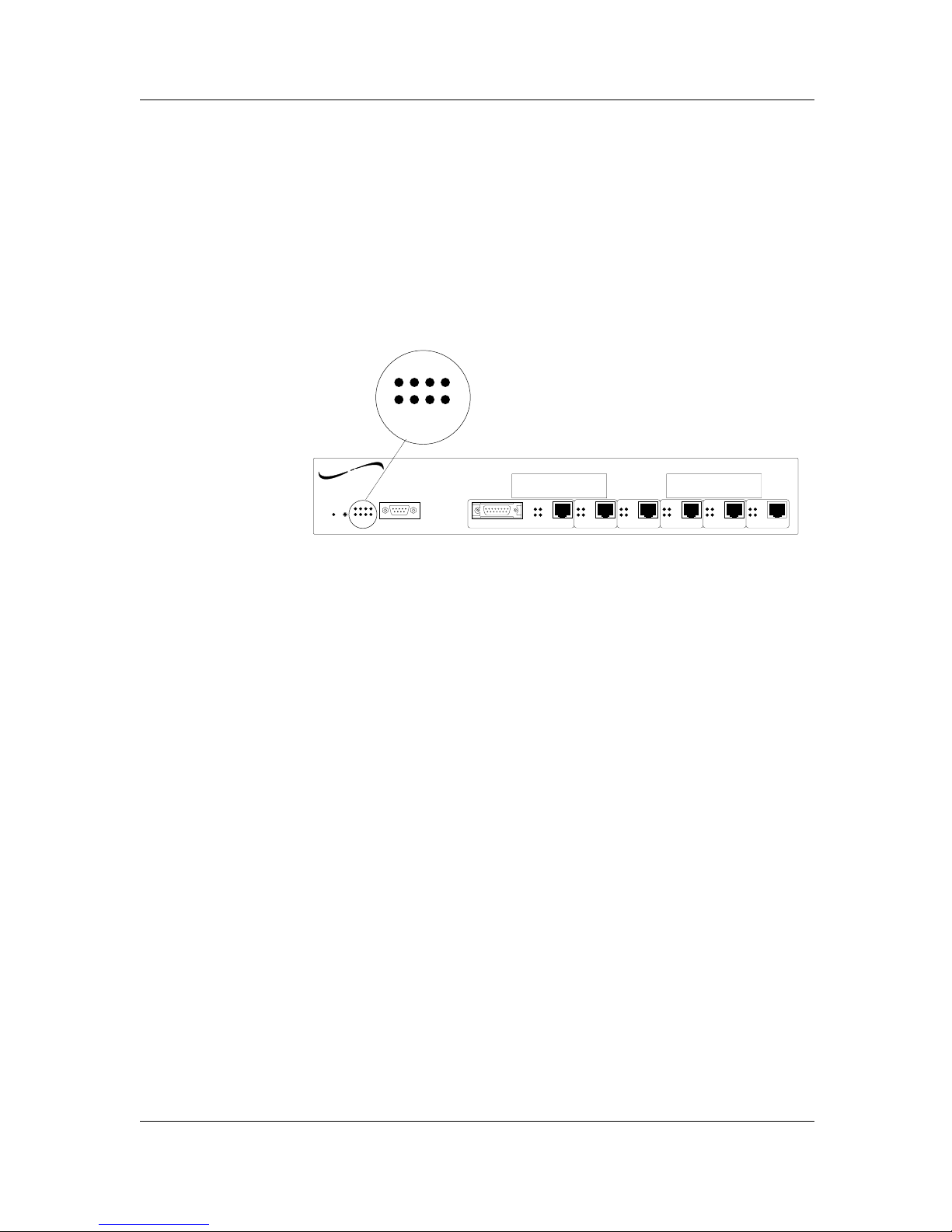
SwitchMaster™ Eight Segment Bridge operation is monitored by observing
Bridge Status and Segment Status LEDs on the SwitchMaster™ Bridge front
panel.
Monitoring Bridge Status LEDs during Operation
SwitchMaster™ Bridge Status LEDs are located on the SwitchMaster™
Bridge front panel.
NOTE: When the SwitchMaster™ Eight Segment Bridge is functioning
normally, the eight Status indicators cycle in a steady roll. STATIC Bridge
Status LED displays, whether illuminated or not illuminated, indicate
critical SwitchMaster™ Bridge error for which Transition Engineering
Technical Support should be contacted.
At power on or reset, the SwitchMaster™ Eight Segment Bridge cycles
through three distinct operational phases. The operational phase, and the
transitions between operational phases, are monitored by the Bridge Status
LEDs.
Patterns observable in the Bridge Status LEDs include:
• Power on diagnostic test patterns (phase 0)
• Software loading pattern (phase 1)
• Operation pattern (phase 2)
Phase Transitions
The SwitchMaster™ Bridge Status LEDs flash for twenty seconds, indicating
transition from phase 0 to phase 1 and then from phase 1 to phase 2.
4-2
SwitchMaster™/SwitchMasterFL™
TM
SwitchMaster
Eight Segment Bridge
Reset
Power
Status
Serial
Segment 1 Segment 2
Segment 3 Segment 4 Segment 5
Segment 6
RX RX
RX
RX RX
RX
TX
TX
TX TX
TX
TX
COL
LINK
COL
LINK
COL
LINK
COL
LINK
COL
LINK
COL
LINK
X Slot 2 X Slot 1
AUI
Status
networks
TRANSITION
Page 37
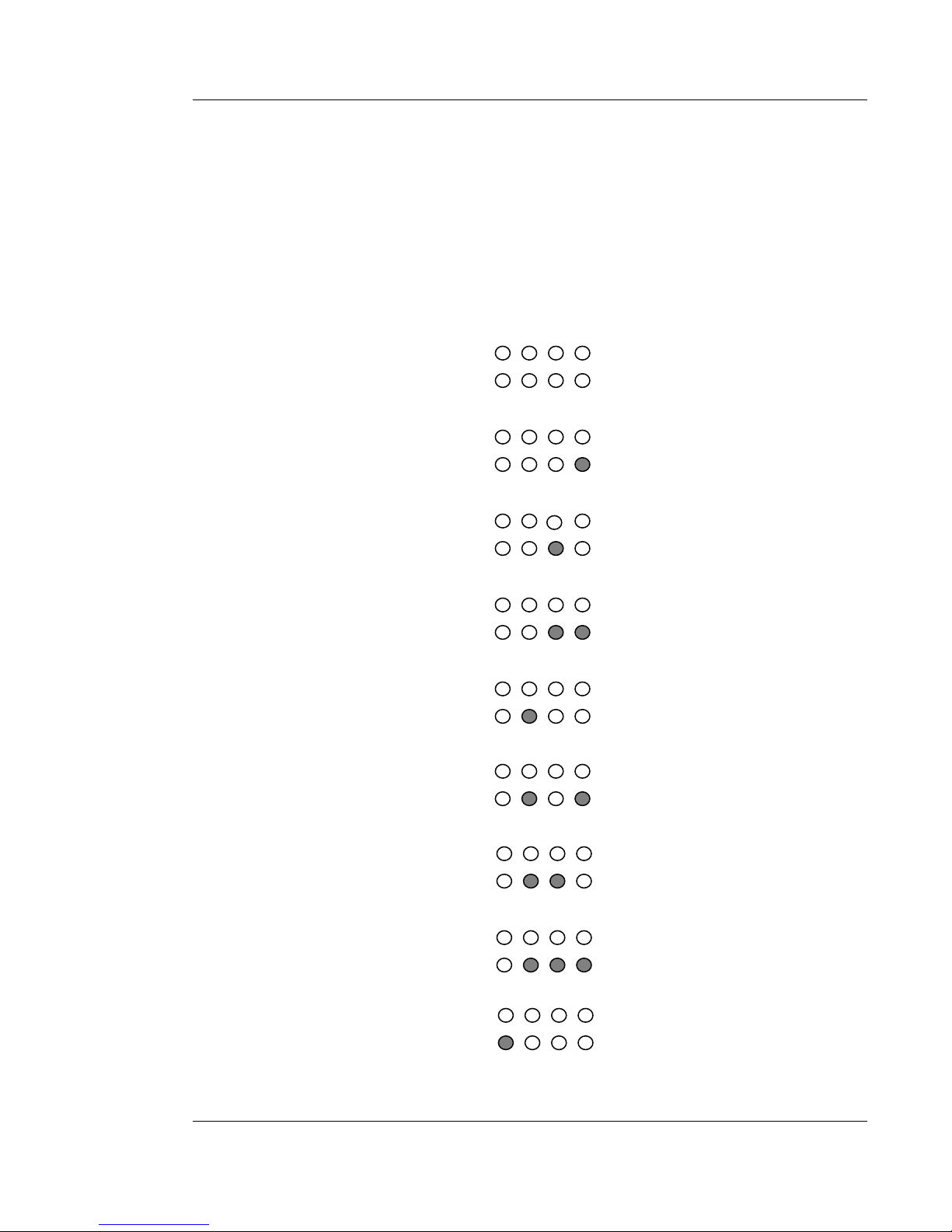
Phase 0 Power On Diagnostic Tests
At power on, the Status LEDs cycle through diagnostic test patterns as
internal SwitchMaster™ Bridge software tests: Flash, serial port, dynamic
RAM, static RAM, dual port memory, and each of the Ethernet ports.
During each of the diagnostic tests, the four Bridge Status LEDs at the top
of the Status LEDs cycle in a steady right to left pattern to indicate test
progress. The pattern of the four LEDs at the bottom of the Status LEDs
indicates the hardware being tested.
4-3
EIGHT SEGMENT BRIDGE
4. OPERATION
Flash Test
Serial Port Test
Dynamic RAM Test
Dynamic RAM Test
Static RAM Test
Static RAMTest
Dual Port Test
Dual Port Test
Ethernet Port 1 Test
Page 38
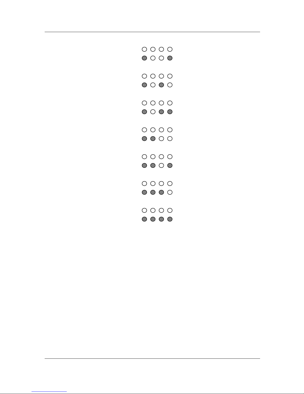
Phase 1 Software Loading
SwitchMaster™ Bridge phase 1 operation loads configuration software. The
default is loading configuration software from the SwitchMaster™
EEPROM.
Optionally, during phase 1 operation, configuration software can be
loaded from a network server using the bootp function. During power on,
at some point in the reset, the top row of Status LEDs flashes continuously
while the bottom row of Status LEDs are steadily illuminated, indicating
that the SwitchMaster™ Bridge software can be interrupted by an optional
user input. During this period, at the attached terminal, press the space bar
to load the configuration software from the attached terminal or other
network server.
Phase 2 Normal Operation
SwitchMaster™ Bridge phase 2 operation is the normal operating mode.
During phase 2 operation, configuration software can be displayed and/or
modified at an attached ASCII terminal.
4-4
SwitchMaster™/SwitchMasterFL™
Ethernet Port 2 Test
Ethernet Port 3 Test
Ethernet Port 4 Test
Ethernet Port 5 Test
Ethernet Port 6 Test
Ethernet Port 7 Test
Ethernet Port 8 Test
Page 39
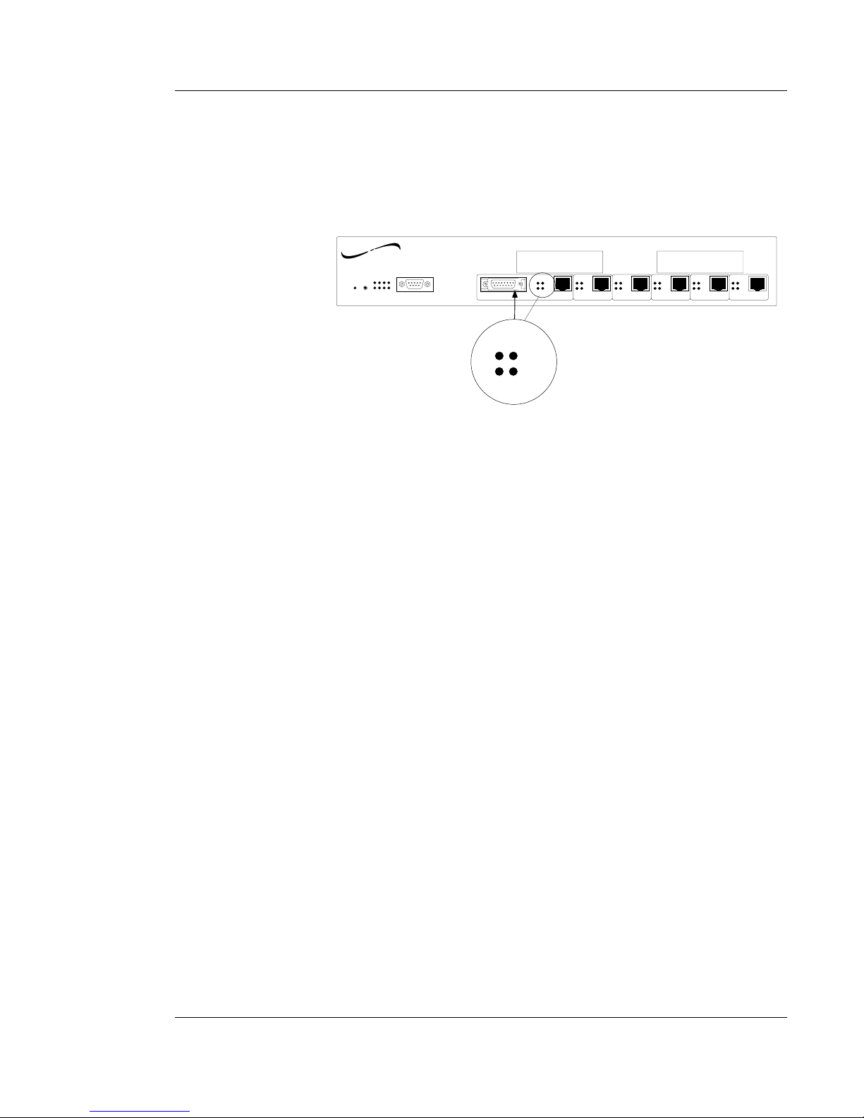
Monitoring Segment Status LEDs
SEGMENT 1 AUI STATUS INDICATORS
WhenSegment 1 is connected through the AUI connector, the Segment 1
status LEDs indicate AUI network activity.
When a SwitchMaster™ AUI is actively connected to normal mode (half
duplex) Ethernet, the Segment LEDs indicate the following AUI conditions:
Tx illuminated during TRANSMIT
Rx illuminated during RECEIVE
COL illuminated during COLLISION
LINK NOT ILLUMINATED (disabled)
When a SwitchMaster™ AUI is actively connected to full duplex Ethernet,
the Segment AUI LEDs indicate the following.
Tx illuminated during TRANSMIT
Rx NOT ILLUMINATED (disabled)
COL NOT ILLUMINATED (disabled)
LINK NOT ILLUMINATED (disabled)
NOTE: When neither the Segment 1AUI port nor the Segment 1 RJ-45 port
is used, the Segment 1 LEDs indicate the following.
Tx illuminated during any network activity
Rx NOT ILLUMINATED (disabled)
COL NOT ILLUMINATED (disabled)
LINK NOT ILLUMINATED (disabled)
4-5
EIGHT SEGMENT BRIDGE
4. OPERATION
TM
SwitchMaster
Eight Segment Bridge
Reset
Power
Status
Serial
Segment 1 Segment 2
Segment 3 Segment 4 Segment 5
Segment 6
RX RX
RX
RX RX
RX
TX
TX
TX TX
TX
TX
COL
LINK
COL
LINK
COL
LINK
COL
LINK
COL
LINK
COL
LINK
X Slot 2 X Slot 1
AUI
RX
TX
COL
LINK
networks
TRANSITION
Page 40
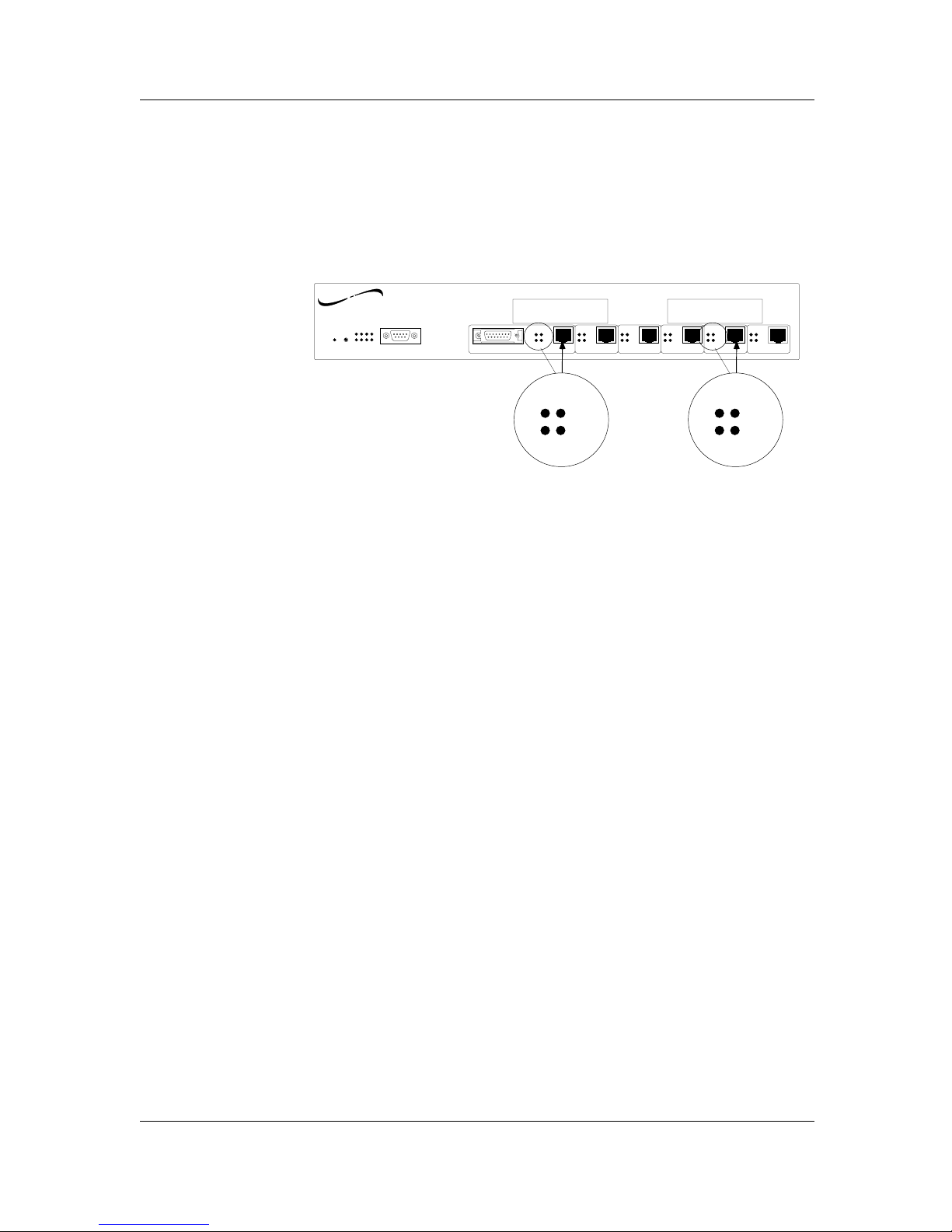
SEGMENT 1 RJ-45 STATUS INDICATORS
WhenSegment 1 is connected through the RJ-45 connector, the Segment 1
status LEDs indicate RJ-45 connection status.
SEGMENT 2-SEGMENT 6 RJ-45 STATUS INDICATORS
When Segment 2 through Segment 6 RJ-45 are connected, the Segment
status LEDs indicate RJ-45 connection status.
When a SwitchMaster™ RJ-45 is actively connected to normal mode
Ethernet, the Segment RJ-45 LEDs indicate the following.
Tx illuminated during TRANSMIT
Rx illuminated during RECEIVE
COL illuminated during COLLISION
LINK illuminated when LINK connection is active
When a SwitchMaster™ RJ-45 is actively connected to full duplex Ethernet,
the Segment RJ-45 LEDs indicate the following.
Tx illuminated during TRANSMIT
Rx illuminated during RECEIVE
COL NOT ILLUMINATED (disabled)
LINK illuminated when LINK connection is active
4-6
SwitchMaster™/SwitchMasterFL™
TM
SwitchMaster
Eight Segment Bridge
Reset
Power
Status
Serial
Segment 1 Segment 2
Segment 3 Segment 4 Segment 5
Segment 6
RX RX
RX
RX RX
RX
TX
TX
TX TX
TX
TX
COL
LINK
COL
LINK
COL
LINK
COL
LINK
COL
LINK
COL
LINK
X Slot 2 X Slot 1
AUI
RX
TX
COL
LINK
RX
TX
COL
LINK
networks
TRANSITION
Page 41
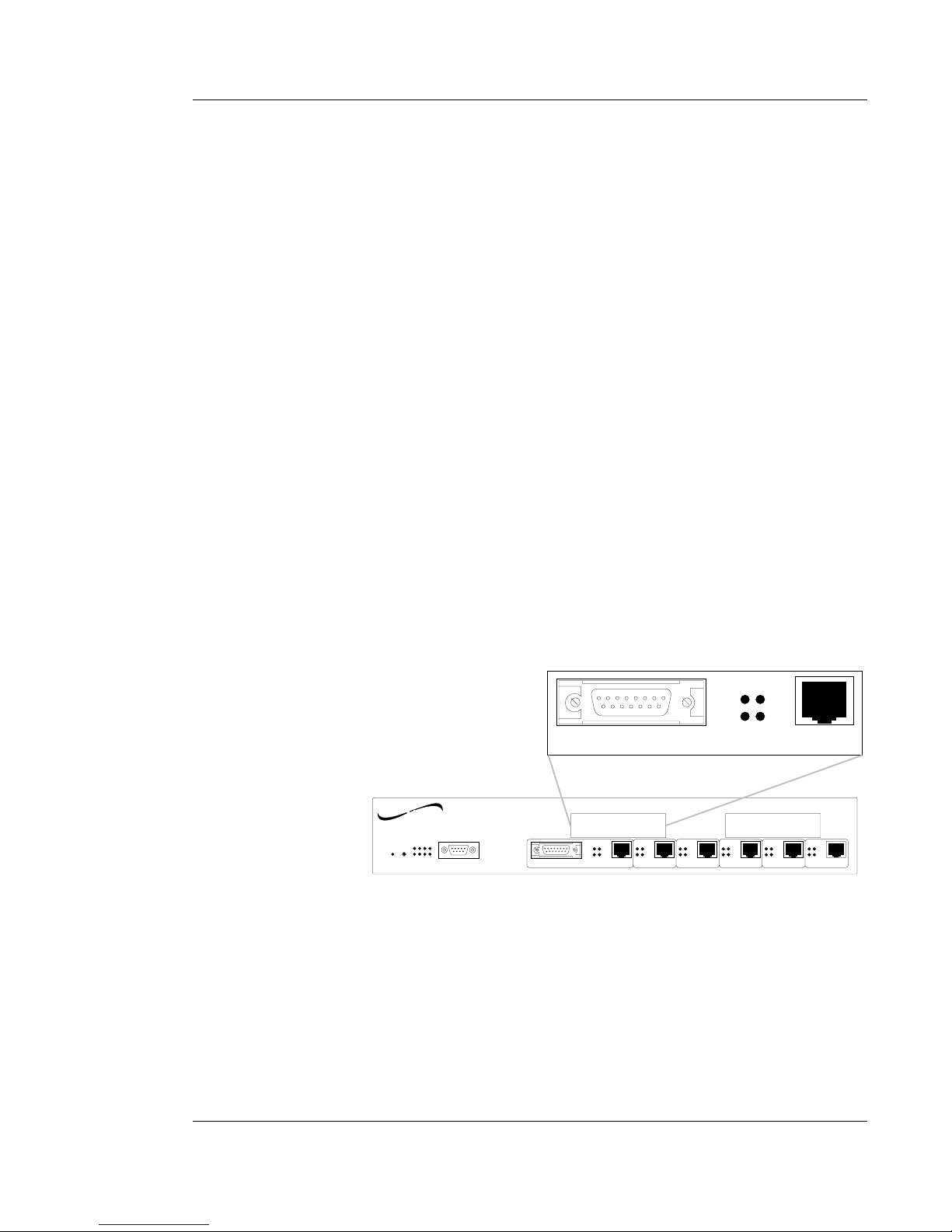
4-7
EIGHT SEGMENT BRIDGE
Monitoring X Slot Card Status Indicators
Full Duplex Ethernet
The Full Duplex Ethernet X Slot Card Status indicators are the same as
Segment 1 Status indicators.
When a SwitchMaster™ AUI is actively connected to normal mode (half
duplex) Ethernet, the Segment LEDs indicate the following AUI conditions:
Tx illuminated during TRANSMIT
Rx illuminated during RECEIVE
COL illuminated during COLLISION
LINK NOT ILLUMINATED (disabled)
When a SwitchMaster™ AUI is actively connected to full duplex Ethernet,
the Segment AUI LEDs indicate the following.
Tx illuminated during TRANSMIT
Rx NOT ILLUMINATED (disabled)
COL NOT ILLUMINATED (disabled)
LINK NOT ILLUMINATED (disabled)
NOTE: When neither the AUI port nor the RJ-45 port is used, the Segment
1 LEDs indicate the following.
Tx illuminated during any network activity
Rx NOT ILLUMINATED (disabled)
COL NOT ILLUMINATED (disabled)
LINK NOT ILLUMINATED (disabled)
4. OPERATION
AUI
RX
COL
LINK
TX
TM
SwitchMaster
Eight Segment Bridge
Reset
Power
Status
Serial
Segment 1 Segment 2
Segment 3 Segment 4 Segment 5
Segment 6
RX RX
RX
RX RX
RX
TX
TX
TX TX
TX
TX
COL
LINK
COL
LINK
COL
LINK
COL
LINK
COL
LINK
COL
LINK
X Slot 2 X Slot 1
AUI
networks
TRANSITION
Page 42
4-8
SwitchMaster™/SwitchMasterFL™
Monitoring X Slot Card Status Indicators
(continued)
100BaseTX Ethernet
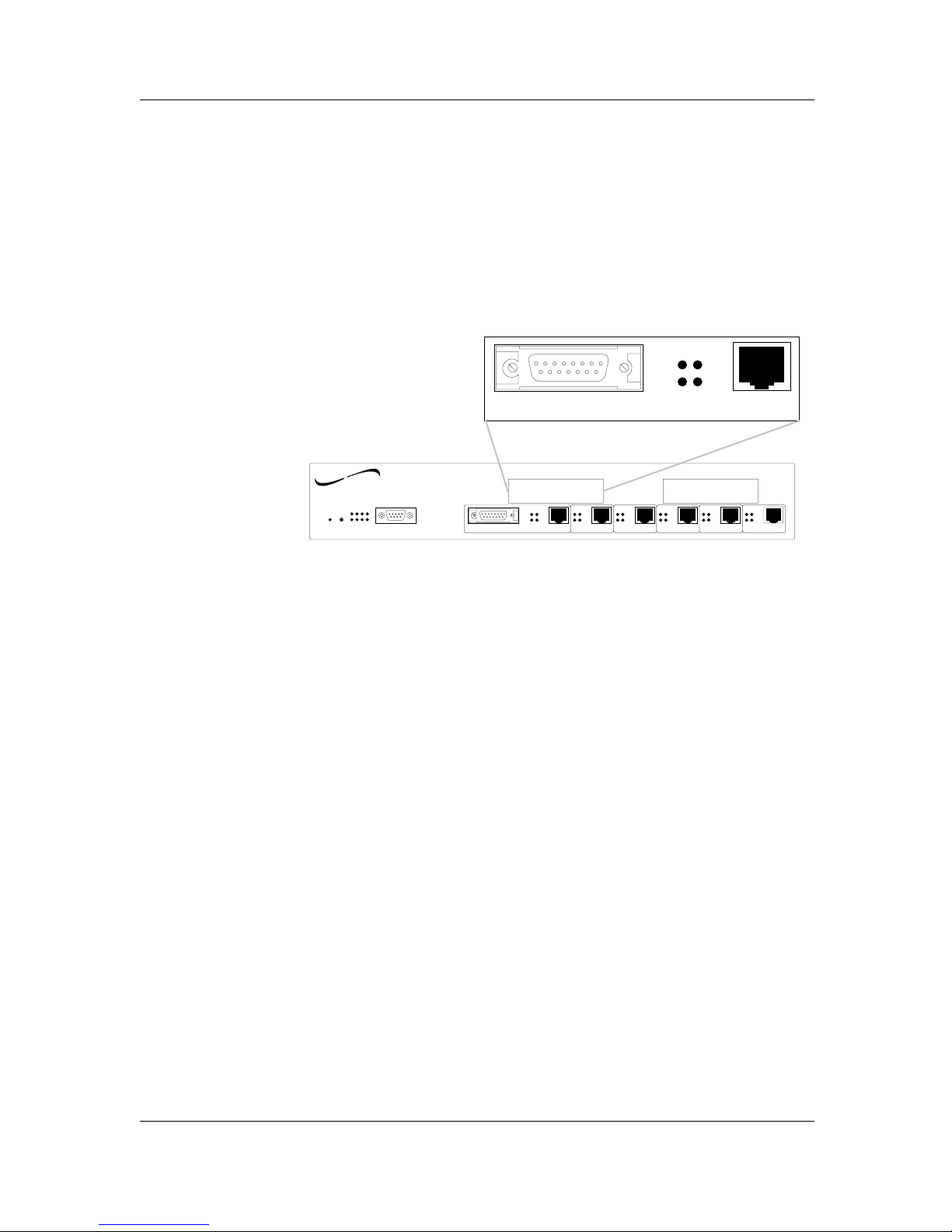
When a SwitchMaster™ 100BaseT X Slot card is installed at either of the
two X Slot locations, the Segment LEDs indicate the following conditions:
Tx illuminated during TRANSMIT
Rx illuminated during RECEIVE
LINK illuminated when connection over 100BaseT media
is good.
AUI
RX
COL
LINK
TX
TM
SwitchMaster
Eight Segment Bridge
Reset
Power
Status
Serial
Segment 1 Segment 2
Segment 3 Segment 4 Segment 5
Segment 6
RX RX
RX
RX RX
RX
TX
TX
TX TX
TX
TX
COL
LINK
COL
LINK
COL
LINK
COL
LINK
COL
LINK
COL
LINK
X Slot 2 X Slot 1
AUI
networks
TRANSITION
Page 43

5-1
EIGHT SEGMENT BRIDGE
5. MAINTENANCE
To assist in SwitchMaster™ Bridge maintenance, this section provides:
• SwitchMaster™ Bridge Fault Isolation Table
• Directions for enabling SwitchMaster™ Bridge recovery by
resetting the SwitchMaster™ Bridge
• Directions for replacing SwitchMaster™ Bridge fuse
• Directions for installing field upgrades by downloading software
updates or installing X-Slot cards.
NOTE: Recovery of a failed SwitchMaster™ Bridge may require the
assistance of TRANSITION Networks Technical Support.
Page 44

5-2
SwitchMaster™/SwitchMasterFL™
5.1 SwitchMaster™ Bridge Fault Isolation Table
Use Table 5-1 for troubleshooting the SwitchMaster™ Bridge. Table 5-1
presents a list of faults and probable causes, presented in the order of
increasing probability, with suggested remedial action.
To use Table 5-1, locate the problem in the FAULT column. In the
PROBABLE CAUSE box next to the fault, find one or more probable
cause(s) associated with the fault. Examine each probable cause in turn,
beginning at the top. When the probable cause is identified, take the
associated corrective action in the CORRECTIVE ACTION column.
FAULT PROBABLE CAUSE CORRECTIVE ACTION
Unit POWER LED Disconnected Connect power cord.
not illuminated power cord.
Improperly For 110-120V use,
installed fuse. fuse should read 110-
120V in upright position;
for 210-240V use, fuse
should read 210-240V in
upright position.
Fuse failure. Replace fuse. (See 5.3.1.)
Power supply Contact TN Technical
failure. Support.
1-800-260-1312
Link LED not Disconnected RJ45 Connect RJ45 cable.
illuminated on cable.
10BaseT port
RJ45 cable failure. Replace RJ45 cable.
Cable failure Check cable assembly or
(open/short). tester or swap cable with
known good cable.
Incorrect RJ45 cable See 3.5.2 for straight-
installed. through/crossover
specifications.
Invalid cable pin- See 3.5.2 for cable
outs. pin-outs
Workstation or Check NIC
server NIC failure. configuration/setup with
manufacturer.
RJ45 connection Contact TN Technical
failure. Support.
Page 45

5-3
EIGHT SEGMENT BRIDGE
FAULT PROBABLE CAUSE CORRECTIVE ACTION
Steady green LED Repeater requires Reset SwitchMaster
illuminated in a reset. Bridge (See 5.2.2)
Unit with no
physical device
present
No console Initialization Reset SwitchMaster™
connection failure Bridge (See 5.2.2)
allowed by
software. Incorrect console Correct cable. (See
cable installed NOTE below.)
User cannot see Repeater requires Reset SwitchMaster
rest of network reset. Bridge (See 5.2.2)
Node is aging SwitchMaster™ Bridge
requires 5 minutes
to age addresses and
to learn new addresses
Loud fan noise Fan failure Contact TN Technical
Support.
1-800-260-1312
Table 5-1. Fault Isolation in the SwitchMaster™ Bridge
5. MAINTENANCE
NOTE
The DB9 serial port on the SwitchMaster™ Bridge is a DTE device. If the
DB9 serial port cable will be attached directly between two DTE
devices, use a null modem cable. If the cable will be attached to a 9600
baud modem, use a straight through DB9 cable. (See Appendix B.)
Page 46
5.2 SwitchMaster™ Bridge Recovery Procedures
Recovery procedures for the SwitchMaster™ Bridge include:
• Resetting the SwitchMaster™ Bridge
• Verifying and optionally modifying Bridge Port Settings
Resetting the SwitchMaster™ Bridge
At power on or reset, the Status LEDs cycle through diagnostic test
patterns as internal SwitchMaster™ Bridge software tests: Flash, serial port,
dynamic RAM, static RAM, dual port memory, and each of the Ethernet
ports. After the diagnostic test patterns, the Status LEDs display a pattern
in which four LEDs remain illuminated while four LEDs flash continuously
to indicate that the SwitchMaster™ Bridge is waiting for optional user
interrupt. Then the Status LEDs cycle in a steady roll to indicate that the
SwitchMaster™ Bridge is fully operational.
Reset the SwitchMaster™ Bridge in any of the following ways:
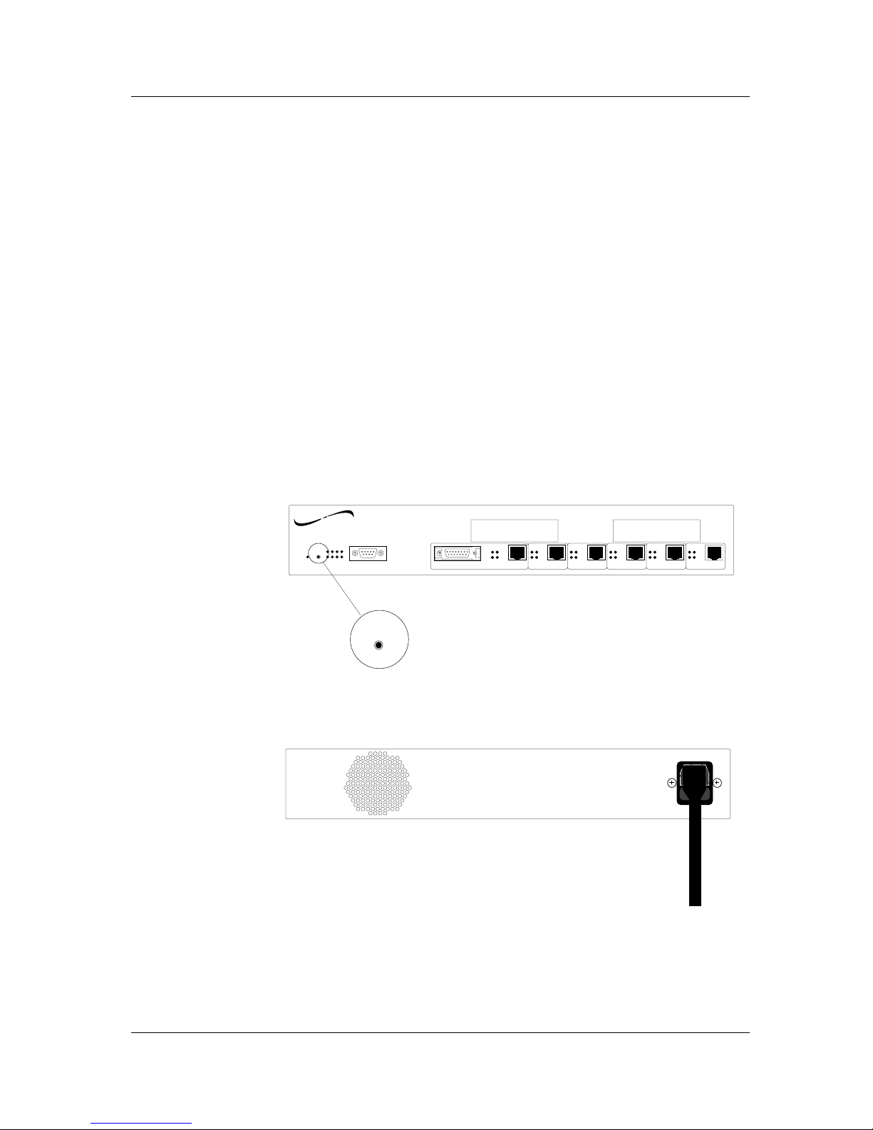
• Press the reset button on the SwitchMaster™ Bridge.
• Disconnect, then reconnect, power cord to the SwitchMaster™
Bridge.
5-4
SwitchMaster™/SwitchMasterFL™
110-120
220-240
TM
SwitchMaster
Eight Segment Bridge
Reset
Power
Status
Serial
Segment 1 Segment 2
Segment 3 Segment 4 Segment 5
Segment 6
RX RX
RX
RX RX
RX
TX
TX
TX TX
TX
TX
COL
LINK
COL
LINK
COL
LINK
COL
LINK
COL
LINK
COL
LINK
X Slot 2 X Slot 1
AUI
Reset
networks
TRANSITION
Page 47
5.3 Replacement Procedures
WARNING: SwitchMaster™ Units contain no user-serviceable parts.
Except for the installation or replacement of X Slot Cards, DO NOT,
UNDER ANY CIRCUMSTANCES, open and attempt to repair
SwitchMaster™ equipment. Failure to observe this warning could result
in electrical shock and personal injury.
NOTE: Failure to observe the above warning will immediately void any
warranty.
Replacing SwitchMaster™ Bridge Fuses
To replace a SwitchMaster™ Unit fuse:
1. Disconnect outlet end of power cord from AC wall socket.
2. Disconnect the power cord from the SwitchMaster™ Unit power
receptacle.
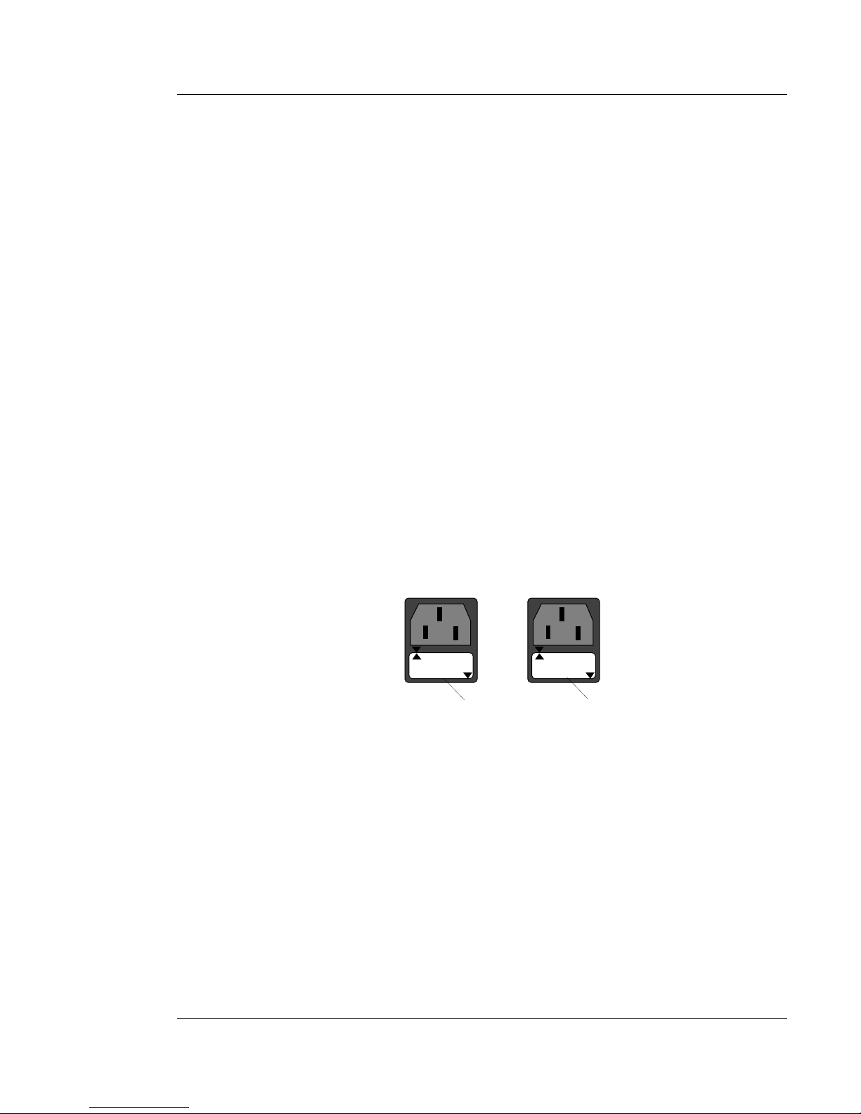
3. Carefully open fuse receptacle, using small flat blade screwdriver.
CAUTION: Replace fuse only with same size and rating. Failure to
observe this caution could result in equipment damage.
NOTE: Installed fuse rating orientation is indicated by reading in lower
right corner of fuse holder.
4. Install replacement fuse holder in correct rating orientation.
5. Close fuse receptacle.
6. Connect power cord to SwitchMaster™ Unit power receptacle.
7. Connect outlet end of the power cord to the AC wall socket.
8. Verify that POWER LED at the front of the SwitchMaster™ Unit is
illuminated.
5-5
EIGHT SEGMENT BRIDGE
5. MAINTENANCE
110-120
110-120
220-240
220-240
110-120 Orientation 220-240 Orientation
Fuse Holder Fuse Holder
Page 48
5-6
SwitchMaster™/SwitchMasterFL™
5.4 SwitchMaster™ Bridge Field Upgrades
SwitchMaster™ Bridge field upgrades include:
• Software Upgrades
Downloading Updated Software
To download updated software:
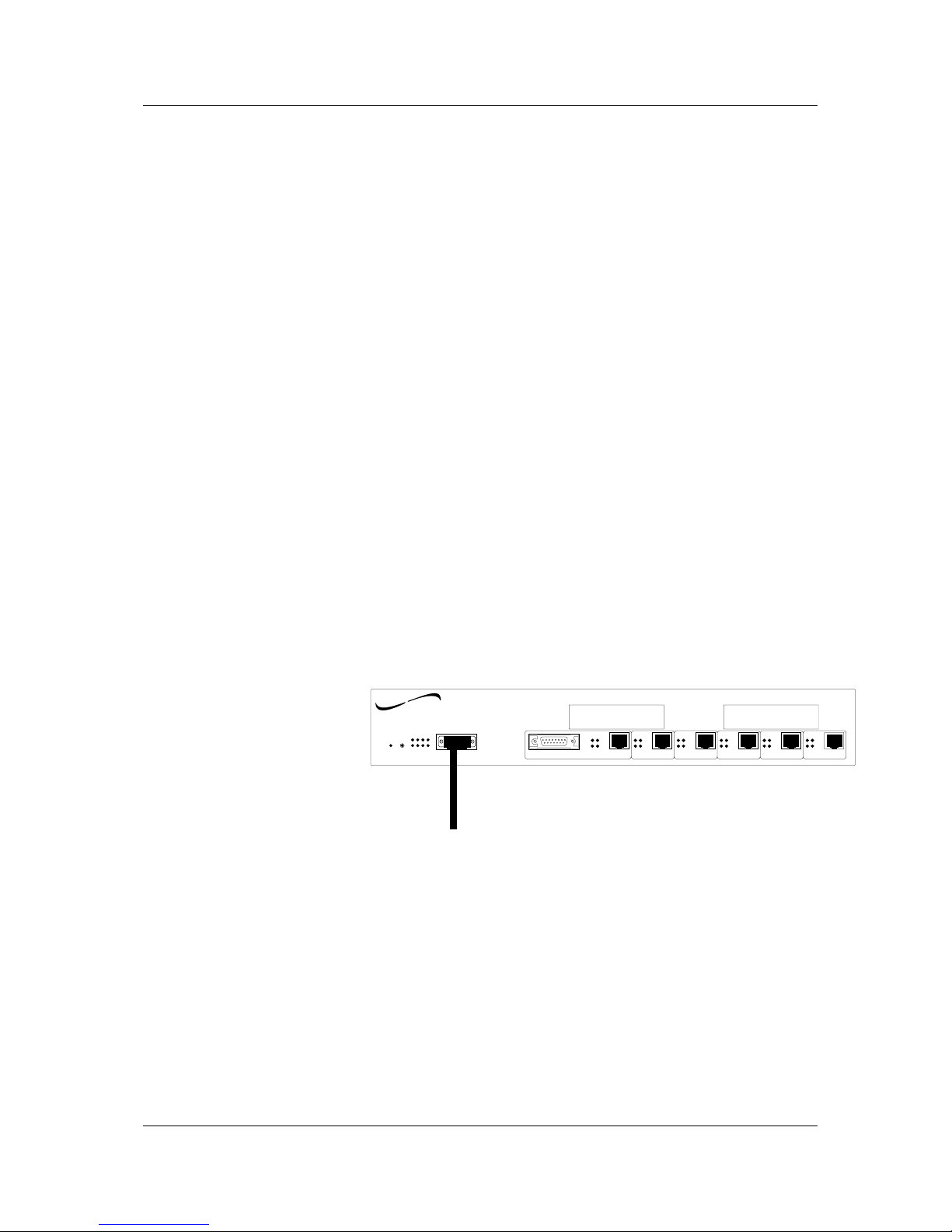
• Connect SwitchMaster™ Bridge to PC with ASCII terminal
• Bring up the SwitchMaster™ Bridge download software
• Transfer TE/OS.bin files.
Connecting to PC with ASCII Terminal
NOTE: The DB9 serial port on the SwitchMaster™ is a DTE device. If the
DB9 serial port cable will be attached directly between two DTE devices,
use a null modem cable. If the cable will be attached to a 9600 baud
modem, use a straight through DB9 cable.
To connect to PC with ASCII terminal:
1. Locate the correct DB9 serial port cable with female DB9 connector.
2. Attach the DB9 serial port female cable connector to the male DB9
serial port connector on the SwitchMaster.
3. Attach the other end of the DB9 serial port cable (directly or indirectly
through a modem) to an ASCII terminal or terminal emulator.
NOTE: The SwitchMaster™ is shipped with standard serial port parameter
values:
baud 9600
stop bits 1
data bits 8
parity NONE
Using methods appropriate to the attached PC and terminal, verify that the
serial port parameters of the attached terminal match the SwitchMaster™
Bridge port parameter values. If necessary, modify the attached terminal
port parameter values and reset the SwitchMaster™ Bridge (See 5.2.1).
TM
SwitchMaster
Eight Segment Bridge
Reset
Power
Status
Serial
Segment 1 Segment 2
Segment 3 Segment 4 Segment 5
Segment 6
RX RX
RX
RX RX
RX
TX
TX
TX TX
TX
TX
COL
LINK
COL
LINK
COL
LINK
COL
LINK
COL
LINK
COL
LINK
X Slot 2 X Slot 1
AUI
To ASCII Terminal
networks
TRANSITION
Page 49
Bringing Up the SwitchMaster™ Bridge Download Software
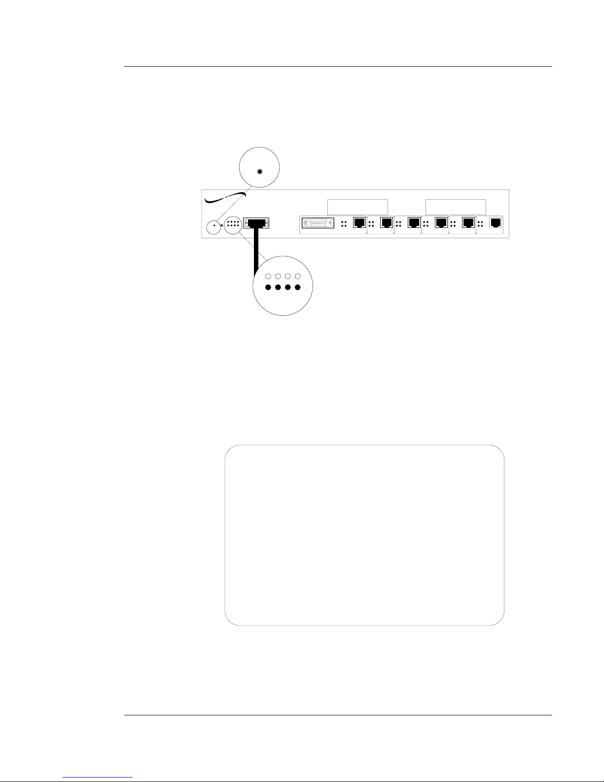
To bring up the SwitchMaster™ Bridge download software:
1. Use a small screwdriver, bent paper clip, or other small device to reset
the SwitchMaster™ Bridge by depressing the internal reset switch.
The Status Indicators cycle through initial diagnostic patterns, then the
upper four status LEDs flash continuously to indicate that the
SwitchMaster™ Bridge software is ready to accept user input.
2. While the upper Status LEDs are flashing continuously, at the attached
ASCII terminal, press the <space> key.
The X MODEM FILE DOWNLOAD MENU comes up:
NOTE: If there is no keyboard entry while the upper Status LEDs are
flashing continuously, the SwitchMaster™ Bridge continues onto normal
Phase 2 operation.
5-7
EIGHT SEGMENT BRIDGE
5. MAINTENANCE
TM
SwitchMaster
Eight Segment Bridge
Reset
Power
Status
Serial
Segment 1 Segment 2
Segment 3 Segment 4 Segment 5
Segment 6
RX RX
RX
RX RX
RX
TX
TX
TX TX
TX
TX
COL
LINK
COL
LINK
COL
LINK
COL
LINK
COL
LINK
COL
LINK
X Slot 2 X Slot 1
AUI
Status
Reset
networks
TRANSITION
Transition Engineering Inc. (c) 1994, 1995
0 ==> Continue Bootup Process
1 ==> Change BAUD rate
2 ==> Standby For a Modem Connection
3 ==> Download BOOTP code using XMODEM/CRC
4 ==> Download BOOTP code using XMODEM
5 ==> Download TE/OS code using XMODEM/CRC
6 ==> Download TE/OS code using XMODEM
7 ==> Reset SwitchMaster
ENTER CMD ==>
SwitchMaster :: 8 Port Switching System
Console Port Activated
X MODEM FILE DOWNLOAD MENU
Page 50

5-8
SwitchMaster™/SwitchMasterFL™
Transferring TE/OS.bin software
To transfer the TE/OS.bin software.
1. Load the TRANSITION Networks software update disk into the ASCII
terminal PC.
2. Using methods appropriate to the attached terminal, download the
bootp.bin code from the TRANSITION Networks software update into
the reserved SwitchMaster™ Bridge memory.
3. At the X MODEM FILE DOWNLOAD MENU display on the attached
ASCII terminal, depending upon the protocols installed on the
terminal ASCII terminal PC, select one of the menu options:
5. Download TE/OS code using X_MODEM/CRC
6. Download TE/OS code using X_MODEM
by typing and entering the number 5 or the number 6.
The SwitchMaster™ Bridge reserves memory for downloading the
update software.
4. Using methods appropriate to the attached terminal, download the
TE/OS.bin code from the TRANSITION Networks software update disk
into the reserved SwitchMaster™ Bridge memory.
5. To continue to normal Phase 2 operation, at the X MODEM FILE
DOWNLOAD MENU display on the attached ASCII terminal, select
the menu option
0. Continue Bootup Process
by typing and entering the number 0.
NOTE: If the files load successfully, the system continues to Phase 2
operation.
Page 51
Installing X-Slot Card in SwitchMaster™ Unit
WARNING: DISCONNECT POWER CORD from SwitchMaster™ Unit
before installing the X-Slot card. Failure to observe this warning could
result in personal injury or death from electrical shock.
WARNING: AVOID CONTACT WITH POWER SUPPLY during X-Slot
card installation. Failure to observe this warning could result in personal
injury from electrical shock caused by capacitive discharge.
CAUTION: Wear a grounding device and observe electrostatic discharge
precautions when installing the X-Slot card. (Attach free end of
grounding device to any bare metal on SwitchMaster™ Unit chassis.)
Failure to observe this caution could result in circuit board failure.
Tools: Medium Phillips screwdriver
To install the X-Slot card:
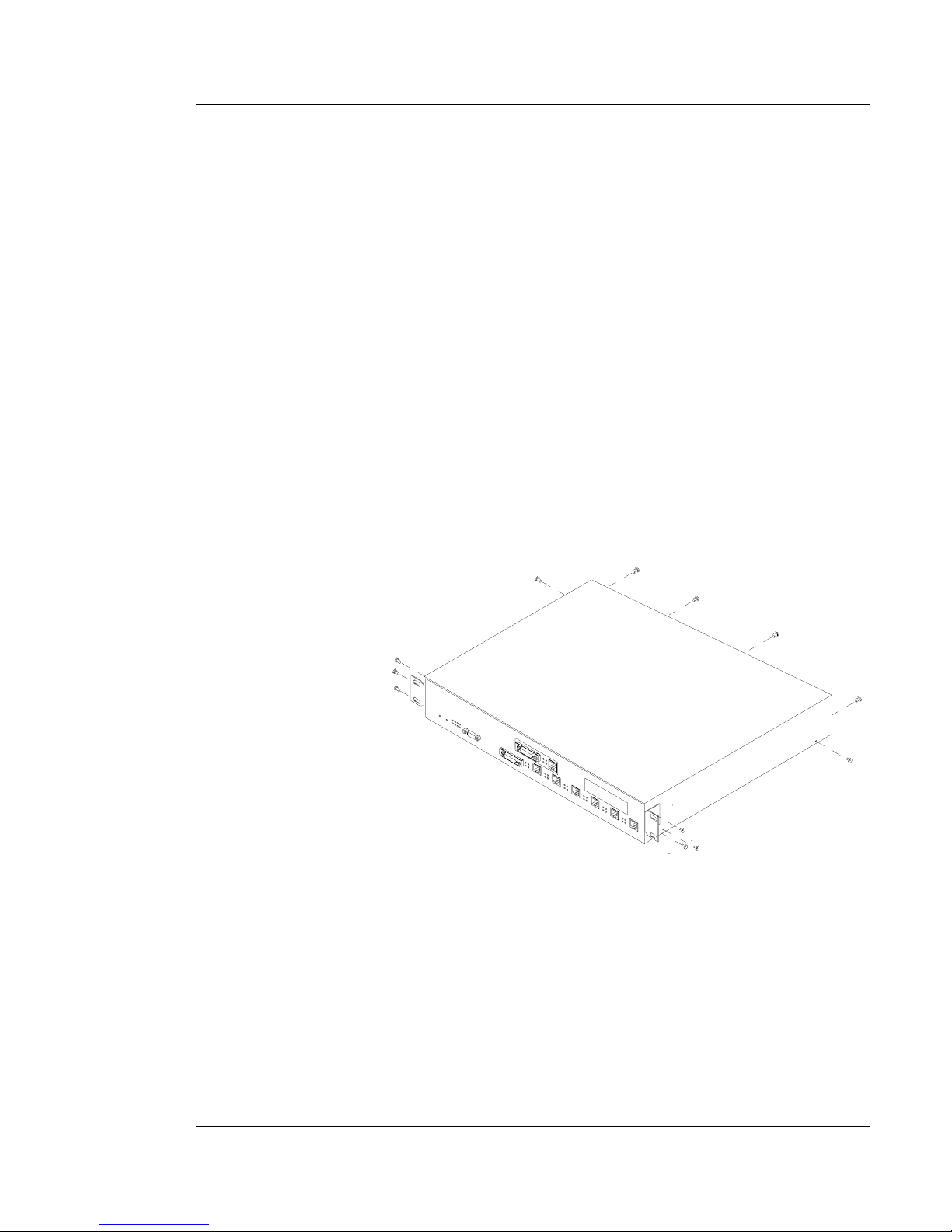
1. Place SwitchMaster™ Unit on table or other stable surface.
2. Using medium Phillips screwdriver, remove twelve (12) screws that
secure cover to SwitchMaster™ Unit.
3. Slide cover approximately one inch toward back of SwitchMaster™
Unit to disengage cover from SwitchMaster™ Unit.
4. Lift cover from SwitchMaster™ Unit and set aside.
5-9
EIGHT SEGMENT BRIDGE
5. MAINTENANCE
Page 52
5-10
SwitchMaster™/SwitchMasterFL™
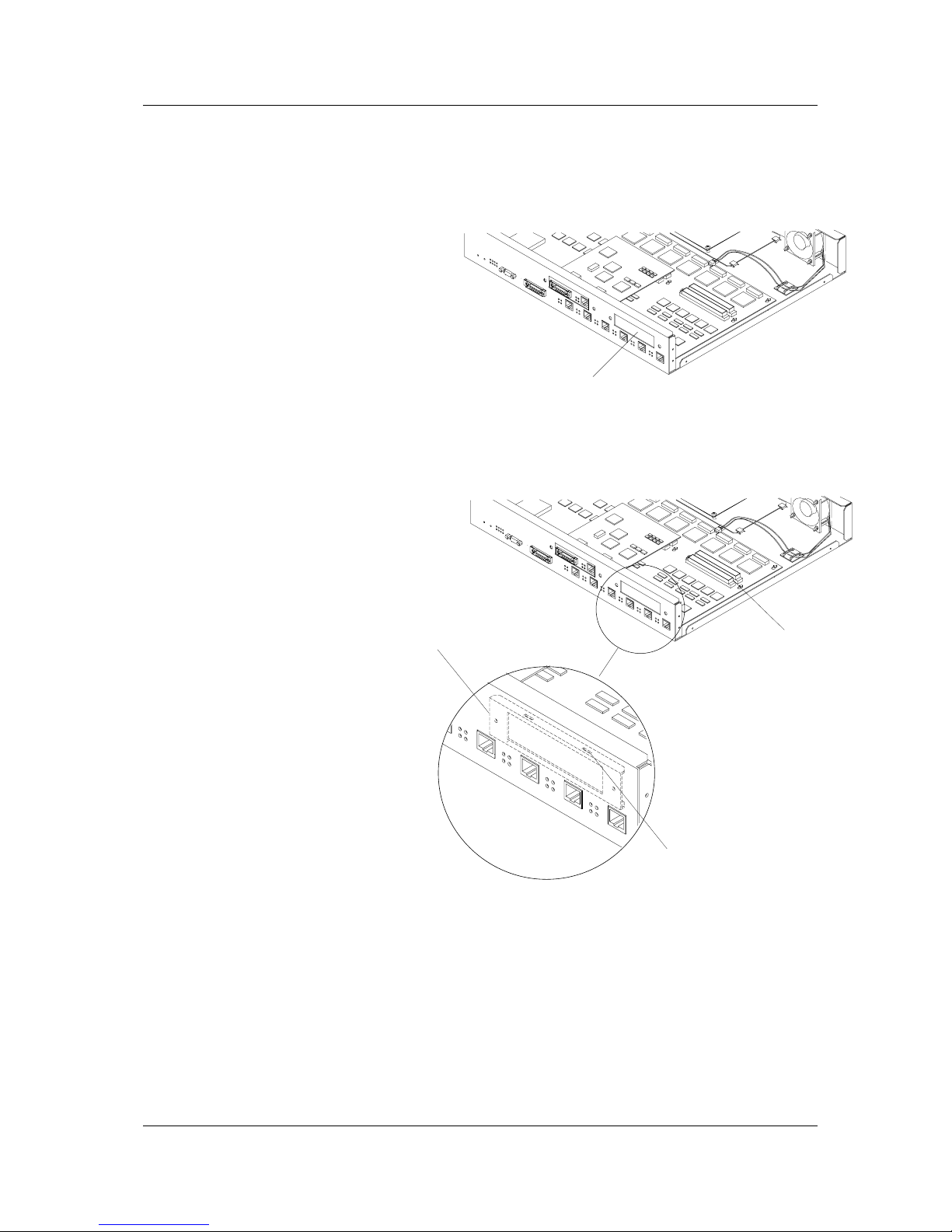
5. From SwitchMaster™ Unit inside front, remove knockout plate from
SwitchMaster™ Unit by holding screwdriver against knockout plate
and striking firmly until knockout plate falls onto the table or other flat
surface and free of the SwitchMaster™ Unit..
6. Locate internal X-Slot card mounting bracket installed at
SwitchMaster™ Unit inside front.
NOTE: The X-Slot card attaches to two (2) slots on the internal X-Slot card
mounting bracket and to two (2) 96-pin connectors located on the
SwitchMaster™ circuit board inside the SwitchMaster™ Unit.
Knockout Plate
X-Slot Card Mounting
Bracket Slots
Internal X-Slot Card
Mounting Bracket
96-pin connectors
Page 53
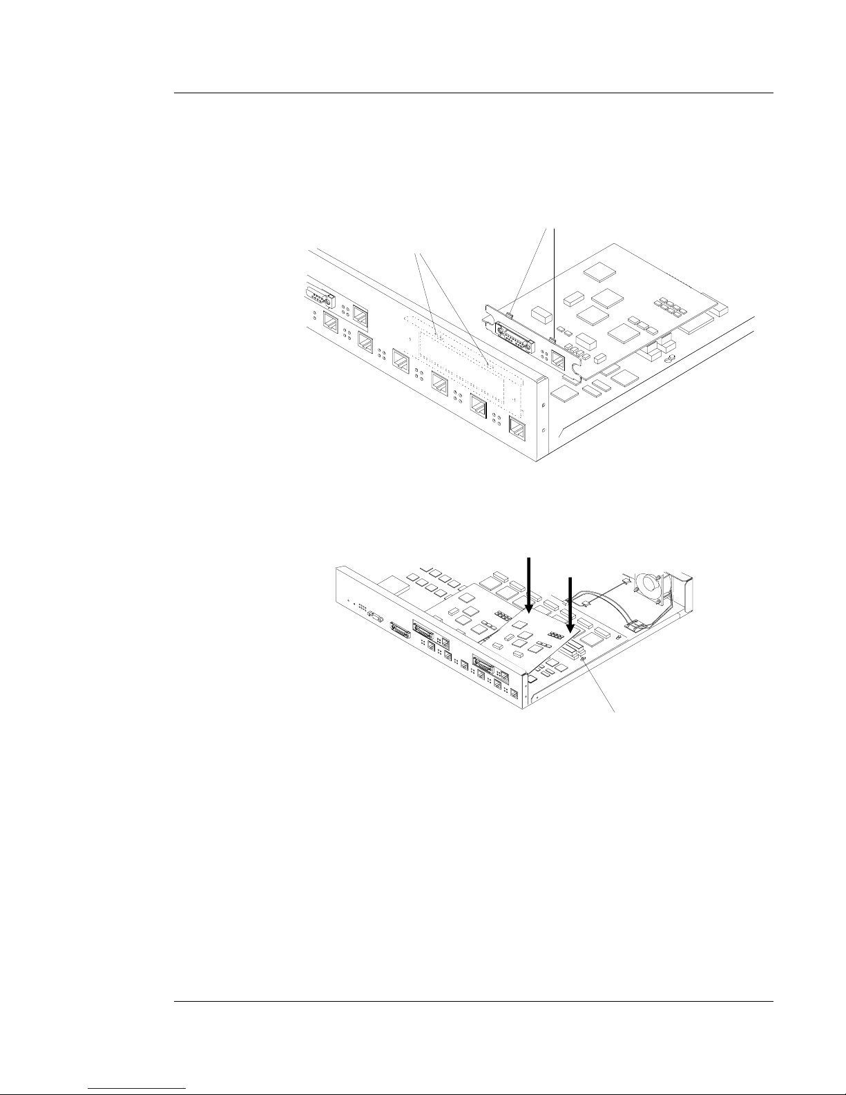
7. Carefully align the X-Slot card mounting tabs with the internal X-Slot card
mounting bracket slots.
8. Slide the X-Slot card mounting tabs into the internal X-Slot Card mounting
bracket slots.
9. Carefully press X-Slot card onto the two (2) 96-pin connectors on the
SwitchMaster™ circuit board.
10. Replace SwitchMaster™ Unit cover.
11. Replace twelve (12) screws that secure SwitchMaster™ Unit cover.
5-11
EIGHT SEGMENT BRIDGE
5. MAINTENANCE
Internal X-Slot Card
Mounting Bracket Slots
X-Slot Card
Mounting Tabs
96-pin connector
Page 54

Page 55

Appendix A. Technical Specifications
Network Standards
Ethernet IEEE 802.3 10BaseT, 10Base2, 10BaseFL, and 10Base5
Cable Type
22, 24, or 26 AWG twisted shielded pair cable, level 3 or higher.
Universal Power Supply
Input Range: 85 to 265 VAC at 47 to 63 Hz. Rated at 40 watts maximum.
AC Input:
TE PN Requirement Location
3344 120 volts, 60 hertz USA/Canada/Mexico
3344 100 volts, 50-60 hertz Japan
3347 230 volts, 50 hertz Europe
3348 240 volts, 50 hertz Australia
3349 240 volts, 50 hertz United Kingdom
Operating Environment
Temperature: 32° to 122° F (0° to 50° C)
Humidity: 10% to 90% non-condensing
Altitude: 0 to 10,000 feet
Dimensions
Height 1.625” (4cm) Width 19” (48cm) Depth 8“ (20cm).
A-1
APPENDIX
EIGHT SEGMENT BRIDGE
Page 56

Page 57
B-1
APPENDIX
EIGHT SEGMENT BRIDGE
Appendix B. Cable Specifications
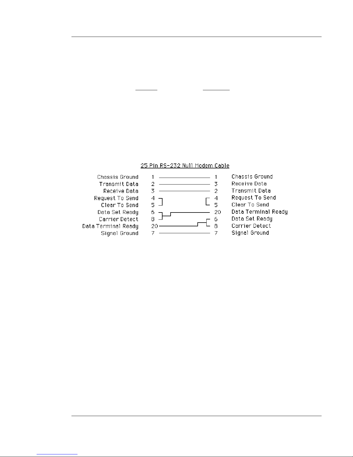
A. Null Modem Cable Specifications
The table below shows the pin assignments for the DB9 cable.
Function Mnemonic
Carrier Detect CD
Receive Data RXD
Transmit Data TXD
Data Terminal Ready DTR
Signal Ground GND
Data Set Ready DSR
Request To Send RTS
Clear To Send CTS
Ring Indicator RI
B. 10Base5 Cable Specifications
The AUI cable must be IEEE approved. Attach one end of the cable to a DTE port and the other end
to a DCE port or transceiver.
Note: The total length of a cable segment must be less than 50 meters (150 feet).
C. 10BaseFL Cable Specifications
The IEEE 802.3 standard for fiber optic segments are listed below:
• 62.5/125µm multimode fiber (recommended).
• 100/140 µm multimode fiber.
• 85 µm multimode fiber.
• 50/125 µm multimode fiber.
Page 58

B-2
SwitchMaster™/SwitchMasterFL™
D. 10BaseT Cable Specifications
The following describes the specifications when twisted pair is used. Either shielded or
unshielded twisted pair can be used. The physical characteristics must meet or exceed
those set forth by the IEEE 802.3 10BaseT specifications. Generally, Level 3 wire or better is recommended. The cable must have a minimum of 2 pairs of twisted 26 to 22
AWG wire.
Note: Do not use flat or “silver satin” wire.
Gauge 26 to 22 AWG
Attenuation Less than 11.5 dB, 5 - 10 MHz
Differential Characteristic 85 - 110 Ω @ 10 MHz Impedance
Maximum Distance 100 Meters (330 Feet)
E. RJ-45 Pin Specifications
Individual wires that make up a straight through twisted pair modular cable are shown
below.
Each pair has designated pin connections on an RJ-45 modular connector. There are
only two active pairs in a 10BaseT network, pins 1 & 2 and 3 & 6. Use only dedicated
wire pairs (such as blue/white, white/blue, orange/white, white/orange, etc.).
Hub Terminal
RJ-45 Male RJ-45 Male
1 - - - - - - - - - - - - - - - - - - - - - - - - 1
2 - - - - - - - - - - - - - - - - - - - - - - - - 2
3 - - - - - - - - - - - - - - - - - - - - - - - - 3
6 - - - - - - - - - - - - - - - - - - - - - - - - 6
The following are the pins for a crossover cable to cascade hubs or connect transceiver
to transceiver.
Hub to Hub
Terminal to Terminal
RJ-45 Male RJ-45 Male
1 - - - - - - - - - - - - - - - - - - - - - - - 3
2 - - - - - - - - - - - - - - - - - - - - - - - 6
3 - - - - - - - - - - - - - - - - - - - - - - - 1
6 - - - - - - - - - - - - - - - - - - - - - - - 2
F. 10Base2 Cable Specifications
The IEEE 802.3 standard for a thin coax segment is listed below:
• Maximum distance of 185 meters (610 feet) at 50 ohms.
Page 59

C-1
APPENDIX
EIGHT SEGMENT BRIDGE
Appendix C. Segment Distance
The IEEE 802.3 CSMA/CD specification has defined standards which are differentiated by the operating link, the type of signaling, the type of media and distances supported. The following chart
highlights the characteristics of the major standards:
10BaseT
10Base2 10Base5
FOIRL 10BaseFB 10BaseFL 10BaseFP
Operating rate 10 10 10 10 10 10 10 (Mbps)
Signaling
baseband baseband baseband baseband baseband baseband baseband
Max Segment 100 185 500 1000 2000 2000 500
Length (Meters) (328 ft) (607 ft) (1640 ft) (3280 ft) (6560 ft) (6560 ft) (1640 ft)
MAUs/ 2 30 100 2 2 2 2
Segment
Medium
unshielded 50 ohm 50 ohm fiber fiber fiber fiber
twisted pair coaxial coaxial optic optic optic optic
(thinnet) (thicknet)
Topology star bus bus star star star star
Notes:
4 Repeaters/ 5 Repeaters/ 5 Repeaters/
Backbone Backbone Backbone
When viewing this chart remember that 10Base5 and 10Base2 use bus topology where multiple
devices tap into a segment. 10BaseT and the various 10BaseF implementations use star topologies
where individual devices connect to a repeater or hub via a single cable or segment. The various
topologies can be interconnected within a single network.
Page 60

Page 61

D-1
APPENDIX
EIGHT SEGMENT BRIDGE
Appendix D. Approved European Power Cord Set
Embossed Alternative Wire
Harmonization Color Codes
Approval Organization Marking Blk Red Ylw
Belgium:Comite
Electrotechnique Beige (CEBEC) CEBEC-HAR 10 30 10
Verband Deutscher Elektrotechniker
(VDE)e, V., Prufstelle VDE-HAR 30 10 10
Technique de l’Electricite (UTE) UTE-HAR 30 30 10
Institute del Marchio Qualita IEMMEQU-HAR 10 30 50
British Approvals Service For
Electric Cables (BASEC-HAR) BASEC-HAR 10 10 30
N.V. tot Keuring van Electro-
technische Matarialien (KEMA) KEMA-KEUR-HAR 10 30 30
Svenska Elecktriska (SMEKO) SMEKO-HAR 10 10 50
Osterreichnischer Verband ful
Electrotechnik (OVE) OVE-HAR 30 10 50
Danmark Elektriske
Materielkontroll (DEMKO) DEMKO-HAR 30 10 30
Institute for Industrial Research
and Standards (IIRS) IRS-HAR 30 30 50
Norges Elektriske
Materielkontroll (NEMKO) NEMKO-HAR 10 10 70
National Standards Authority of
Ireland (NSAI) NSAI-HAR 30 30 50
Page 62

Page 63

E-1
APPENDIX
EIGHT SEGMENT BRIDGE
Warranty Statement
A. Five Year Warranty
Transition Networks, Inc. (TN) warrants, for a period of five years, that TN products (with the
exception of power supplies and fans that TN warrants for two years) will be free from defects in
materials and workmanship, and will be in conformity with TN’s specifications.
TN’s warranty on products manufactured by or assembled for TN in accordance with a customer’s
specifications, is a five-year warranty that the goods conform to such specifications.
The warranty is invalidated if the goods have been subject to alterations, misuse, accident, Acts of
God (e.g., damage by floods, lightning strikes, Etc.), tampering, improper maintenance, improper
installation, or abuse. If the user is unsure about the proper means of installing or using the equipment, contact TN’s free Technical Support or Network Design Services, which can be reached by:
Telephone 1.800.LAN.WANS or 612.941.7600
Fax 612.941.2322
E-mail [email protected]
Internet http://www.transition.com
THE ABOVE WARRANTY IS EXCLUSIVE AND EXTENDS ONLY TO PRODUCTS ASSEMBLED BY
TRANSITION NETWORKS, INC. TO THE EXTENT PERMITTED BY LAW, TN DOES NOT MAKE
AND DISCLAIMS ALL OTHER WARRANTIES, EXCEPT TITLE, EXPRESSED OR IMPLIED, INCLUDING, BUT NOT LIMITED TO, ANY WARRANTY OF DESCRIPTION, MERCHANTIBILITY, FITNESS
FOR A PARTICULAR PURPOSE OR NON-INFRINGEMENT, AND ANY WARRANTY BASED
UPON PRIOR WRITTEN OR ORAL REPRESENTATIONS REGARDING SUCH PRODUCTS MADE
BY TN, ITS EMPLOYEES, AGENTS, OR REPRESENTATIVES.
B. Limitations and Exclusions
If the customer believes any goods sold by TN are defective and within the warranty period, the following general procedure will be followed:
1.Locate the serial number and delivery date of the item(s).
2.Notify TN within the warranty period.
3.TN will promptly issue a return authorization form for the goods.
4.Upon receiving the form, the customer will promptly return the item(s) at customers own
expense, shipped prepaid, to the distributor from which it was purchased, or directly to TN.
TN will only accept goods for return if the following conditions have been met:
1.A return form is obtained from TN.
2.The freight charges have been prepaid by the customer.
3.Goods are re-packed in their original packaging.
If under warranty TN shall, at its option, (1) repair the goods free of charge (2) replace the goods
free of charge, or (3) accept the return of the item(s) and credit the current price to the reseller
(within 90 days of purchase), or (4) if the goods are not under warranty, will repair the item(s) at a
minimum charge of USD $200 (two hundred U.S. dollars) per item.
THIS IS THE EXCLUSIVE REMEDY FOR ANY BREACH OF WARRANTY. IN NO EVENT SHALL
TRANSITION NETWORKS BE LIABLE FOR SPECIAL, INDIRECT, INCIDENTAL OR CONSEQUENTIAL DAMAGES OF ANY KIND, WHETHER FOR BREACH OF ANY CONDITION OF SALE, FOR
NEGLIGENCE, ON THE BASIS OF STRICT LIABILITY, CONTRACT, OR OTHERWISE AND IRRESPECTIVE OF WHETHER TN IS INFORMED BY CUSTOMER OF THE POSSIBILITY OF SUCH
DAMAGES IN ADVANCE OF THIS SALE.
Page 64

E-2
SwitchMaster™/SwitchMasterFL™
The sole purpose of this remedy shall be provided the customer with the replacement or repair of
non-conforming goods in the manner described in this Warranty statement. This exclusive remedy
shall not be deemed to have failed of its essential purpose so long as TN is willing and able to
repair or replace the defective item(s) or refund the purchase price.
TN reserves the right to inspect products claimed to be defective under warranty either at the customer’s location or at TN’s plant. TN assumes no liability for liability charges incidental to the
adjustment, service, repairing, removal or replacement of the product, or other costs, or the
expense of repairs made outside of its factory, except when made with TN’s prior written consent.
Additionally, Transition Networks reserves the right to charge for all testing and shipping incurred,
if after testing, a return is classified as “No Problem Found”.
TN’s total liability in connection with the products and their installation to all persons and from all
causes in the aggregate, whether in contract, tort, or strict liability, shall not exceed the amount
paid to TN for the product directly related to the alleged damage. However, in no event shall TN
have any liability to a customer or any third party for products manufactures according to the customer’s specifications.
C. Return Procedure
The customer must follow this procedure for the return of defective items:
1.Locate the serial number(s) of the item(s) to be returned.
2.Determine the date the item(s) was received.
3.Contact Transition Networks Technical Support to determine if the problem can be corrected
on site.
If not, and the product is covered by warranty, then:
• Call the distributor directly or contact TN.
• Request a Return Material Authorization (RMA).
• Ship the item, prepaid in original packaging to Transition Networks at the above address.
• Include the RMA number on the outside of the carton and/or on the Packing List.
• Include a copy of the RMA form.
• Include a copy of the original invoice or packing list (if possible) to expedite processing.
• The item(s) may be shipped by the customer or the distributor.
• Transition Networks will repair or replace the unit, at TN’s discretion, and cover the cost of
the return freight to the distributor or to the customer, whichever requested the RMA number.
If the item(s) was received more than five years ago, or if the item(s) is no longer covered by war-
ranty for other reasons, then:
• Call the distributor or contact TN.
• Request a Material Repair Authorization number (MRA).
• Ship the item(s), prepaid, in the original packaging to Transition Networks at the above
address.
• Include the MRA number on the outside of the carton add/or on the Packing List.
• Include a copy of the MRA form.
• Include a copy of the original invoice or packing list (if possible) to expedite processing.
• Only the customer (end-user) may send the items(s) to TN.
• TN will contact the customer after the item(s) have been received, inspected, and a cost estimate of the repair determined.
• The repair charges may be billed, with customer’s approval, though the distributor, or on a
prepaid or C.O.D. basis directly to the customer. The charges will include the cost of shipping.
The return authorization numbers are valid only for 90 days from the date issued.
 Loading...