

Transition Networks SGETF1025-100, SGETF1013-100, SGETF1018-100, SGETF1015-100, SGETF1017-100 User Manual
...
COMPLIANCE INFORMATION
UL Listed
C-UL Listed (Canada)
CISPR/EN55022 Class A
EN55024
FCC Regulations
This equipment has been tested and found to comply with the limits for a class A digital device, pursuant
to part 15 of the FCC rules. These limits are designed to provide reasonable protection against harmful
interference when the equipment is operated in a commercial environment. This equipment generates,
uses, and can radiate radio frequency energy and, if not installed and used in accordance with the
instruction manual, may cause harmful interference to radio communications. Operation of this
equipment in a residential area is likely to cause harmful interference, in which case the user will be
required to correct the interference at the user’s own expense.
Canadian Regulations
This digital apparatus does not exceed the Class A limits for radio noise for digital apparatus set out on
the radio interference regulations of the Canadian Department of Communications.
Le présent appareil numérique n'émet pas de bruits radioélectriques dépassant les limites applicables
aux appareils numériques de la class A prescrites dans le Règlement sur le brouillage radioélectrique
édicté par le ministère des Communications du Canada.
European Regulations
Warning
This is a Class A product. In a domestic environment this product may cause radio interference in which
case the user may be required to take adequate measures.
Achtung !
Dieses ist ein Gerät der Funkstörgrenzwertklasse A. In Wohnbereichen können bei Betrieb dieses Gerätes
Rundfunkstörungen auftreten, in weichen Fällen der Benutzer für entsprechende Gegenmaßnahmen
werantwortlich ist.
Attention !
Ceci est un produit de Classe A. Dans un environment domestique, ce produit risque de créer des
interférences radioélectriques, il appartiendra alors à l’utilsateur de prende les measures spécifiques
appropriées
Trademark Notice
All registered trademarks and trademarks are the property of their respective owners.
Copyright Restrictions
© 2001 TRANSITION Networks.
All rights reserved. No part of this work may be reproduced or used in any form or by any means –
graphic, electronic, or mechanical – without written permission from TRANSITION Networks.
Printed in the U.S.A. 33197.C
CAUTION: RJ connectors are NOT INTENDED FOR CONNECTION TO THE
PUBLIC TELEPHONE NETWORK. Failure to observe this caution could result in
damage to the public telephone network.
Der Anschluss dieses Gerätes an ein öffentlickes Telekommunikationsnetz in den EG-Mitgliedstaaten
verstösst gegen die jeweligen einzelstaatlichen Gesetze zur Anwendung der Richtlinie 91/263/EWG
zur Angleichung der Rechtsvorschriften der Mitgliedstaaten über
Telekommunikationsendeinrichtungen einschliesslich der gegenseitigen Anerkennung ihrer
Konformität.
TRANSITION Networks SGETF10xx series Gigabit Ethernet™media converters
connect 1000BASE-TX shielded or unshielded twisted-pair copper cable to
1000BASE-SX or 1000BASE-LX
multimode or singlemode fiber-optic cable.
1000BASE-TX to 1000BASE-SX/LX
Media Converters
SGETF10xx-100
USER’S GUIDE
SGETF1013-100
Provides an RJ-45 twisted-pair copper
1000BASE-T connector and an RX
(receive) and TX (transmit) SC connector
to 850 nm 1000BASE-SX multimode
fiber-optic cable.
SGETF1014-100
Provides an RJ-45 twisted-pair copper
1000BASE-T connector and an RX
(receive) and TX (transmit) SC connector
to 1300 nm 1000BASE-LX singlemode
fiber-optic cable.
SGETF1015-100
Provides an RJ-45 twisted-pair copper
1000BASE-T connector and an RX
(receive) and TX (transmit) SC connector
to 1300 nm 1000BASE-LX singlemode
fiber-optic cable.
SGETF1017-100
Provides an RJ-45 twisted-pair copper
1000BASE-T connector and an RX
(receive) and TX (transmit) SC connector
to 1550 nm 1000BASE-LX singlemode
fiber-optic cable.
SGETF1018-100
Provides an RJ-45 twisted-pair copper
1000BASE-T connector and an RX
(receive) and TX (transmit) MT-RJ
connector to 850 nm 1000BASE-SX
multimode fiber-optic cable.
SGETF1025-100
Provides an RJ-45 twisted-pair copper
1000BASE-T connector and an RX
(receive) and TX (transmit) MT-RJ
connector to 1300 nm 1000BASE-LX
singlemode fiber-optic cable.
SGETF10xx in the Network . . . . . . . .2
Installation . . . . . . . . . . . . . . . . . . . .2
Operation . . . . . . . . . . . . . . . . . . . . .4
Fault Isolation and Correction . . . . .5
Cable Specifications . . . . . . . . . . . . .6
Technical Specifications . . . . . . . . . .7
Compliance Information . . . . . . . . . .8
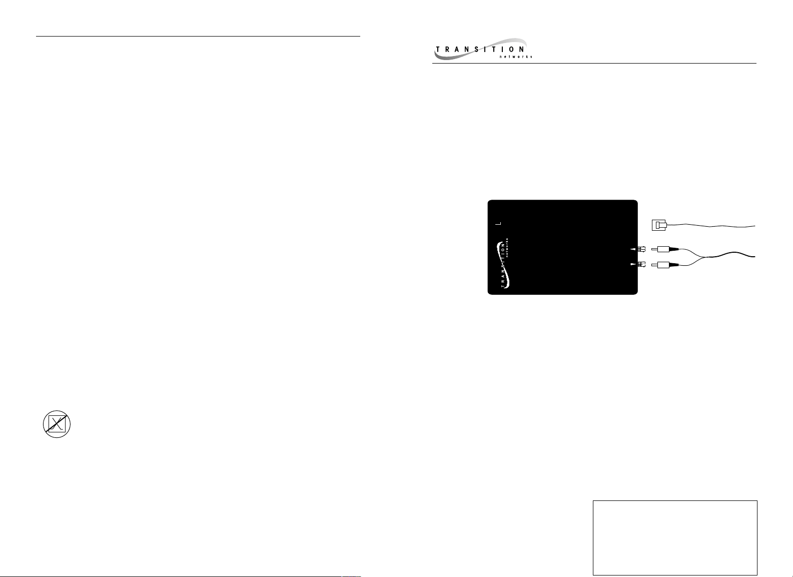
9-12 VDC INPUT
TM
Ethernet
1000BaseT to 1000BaseSX/LX
1000BASE-T Copper
1000Base-T
Media Converter
1000Base-SX/LX
1000BASE-SX/LX Fiber
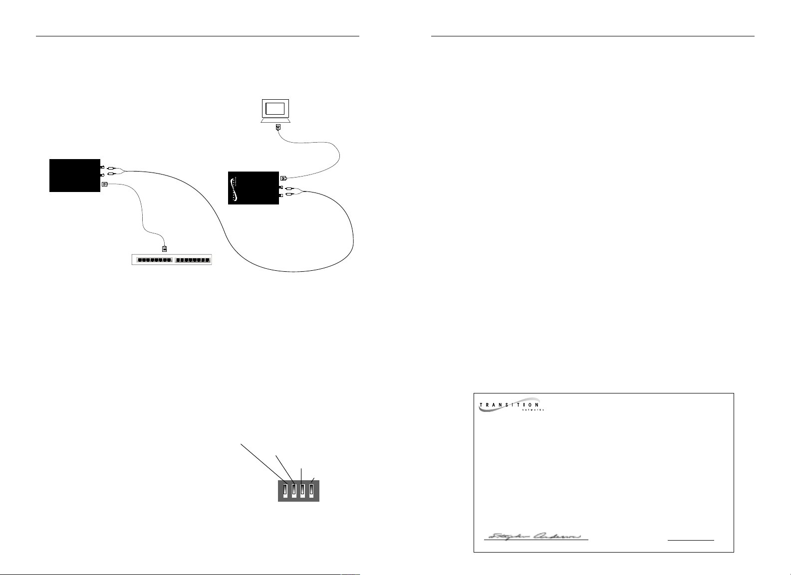
SGETF10xx IN THE NETWORK
Install two SGETF10xx series media converters in series to extend, over fiber,
the distance between two 1000BASE-TX devices.
Use one SGETF10xx media converter to connect a 1000BASE-TX terminal
device and a 1000BASE-SX/LX hub, switch, or router.
NOTE: A TRANSITION Networks stand-alone media converter can be installed
in series with a TRANSITION Networks chassis media converter that has a
related model number, such as an SGETF10xx with a CGETF10xx.
INSTALLATION
Set 4-Position Switch
Use small flatblade screwdriver or similar device to set recessed switches.
Refer to drawing for four-position switch locations.
Full/Half-Duplex Advertisement (UP=Enabled) Allows full-duplex mode.
(DOWN) Allows half-duplex mode.
Pause Advertisement (UP=Enabled)
Allows auto-negotiation pause. (DOWN)
Allows NO auto-negotiation pause.
NOTE: If the Pause feature is present on
all network devices attached to the media
converter(s), enable Pause on the media
converter(s). Otherwise, disable Pause on the media converter(s).
LPT (UP=Enabled) Allows a fault EITHER on the copper OR on the fiber side
of the media coverter to stop signal and data transmission on the other side.
(DOWN) Disables LPT.
TECHNICAL SPECIFICATIONS
Standards IEEE 802.3ab, IEEE 802.3 1998
Data Rate 1000 Mb/s
Dimensions 3.4" x 0.86" x 5.0" (86mm x 22mm x 127mm)
Weight 8 oz (approximate)
Delay 300 nsec
Power Consumption 6.5 Watts
Power Supply Requirements Replace power supply with only the equivalent
input rating (see below) and output rating (unregulated 9-24VDC, 5.5W).
TN PN Requirement Location
12 V, 1.5 A
3507 240 volts, 50 hertz United Kingdom
3342 230 volts, 50 hertz Europe
3340 120 volts, 60 hertz USA/Canada/Mexico
3346 100 volts, 50-60 hertz Japan
3511 240 volts, 50 hertz Australia
3537 IEC320 (with power cord: 3522) South Africa
9 V, 1 A
25039 IEC320, 90-250VAC input NOTE: Requires
appropriate IEC320
power cord for location
25040 120 volts, 60 hertz USA/Canada/Mexico
Environment Typical Operating Temperature*: 0° to 50°C (32°to 122°F )
Storage Temperature: -20°
to 85°C (-4° to 185°F)
Humidity 10-90%, non condensing
Altitude 0-10,000 feet
Warranty Lifetime
DECLARATION OF CONFORMITY
Name of Mfg: Transition Networks
6475 City West Parkway, Minneapolis MN 55344 USA
Model: SGETF10xx-100 Series Media Converters
Part Number(s): SGETF1013-100, SGETF1014-100, SGETF1015-100,
SGETF1017-100
Regulation: EMC Directive 89/336/EEC
Purpose: To declare that the SGETF10xx-100 to which this declaration refers is
in conformity with the following standards.
EMC-CISPR 22: 1985 Class A&B; EN 55022: 1988 Class A&B; EN 50082-1:1992;
EN 60950 A4:1997; IEC 801.2, IEC 801.3, and IEC 801.4; IEC 950
I, the undersigned, hereby declare that the equipment specified above conforms to the
above Directive(s) and Standard(s).
_ January 6, 2001_____
Stephen Anderson, Vice-President of Engineering Date
Full/Half-Duplex Advertisement UP=ON
Pause Advertisement UP=ON
LPT UP=ON
Not Used

CABLE SPECIFICATIONS
Fiber Cable
MULTIMODE
Fiber Optic Cable Recommended: 62.5 / 125 µm multimode fiber
Optional: 100 / 140 µm multimode fiber
85 / 125 µm multimode fiber
50 / 125 µm multimode fiber
SGETF1013 850 nM
Fiber Optic Transmitter Power: min: -10.0 dBm max: -4.0 dBm
Fiber Optic Receiver Sensitivity: min: -17.0 dBm max: -0.0 dBm
Link Budget: 7.0 dB
Typical Maximum Cable Distance*: 220 meters
SGETF1018 850 nM
Fiber Optic Transmitter Power: min: -9.5 dBm max: -4.0 dBm
Fiber Optic Receiver Sensitivity: min: -17.0 dBm max: -0.0 dBm
Link Budget: 7.0 dB
Typical Maximum Cable Distance*: 220 meters
SINGLEMODE
Fiber Optic Cable Recommended: 9 µm singlemode fiber
SGETF1014 1300 nM
Fiber-optic Transmitter Power: min: -13.0 dBm max: -3.0 dBm
Fiber-optic Receiver Sensitivity: min: -20.0 dBm max: -3.0 dBm
Link Budget: 7.0 dB
Typical Maximum Cable Distance*: 5 kilometers
SGETF1015 1300 nM
Fiber-optic Transmitter Power: min: -5.0 dBm max: -0.0 dBm
Fiber-optic Receiver Sensitivity: min: -20.0 dBm max: -3.0 dBm
Link Budget: 15.0 dB
Typical Maximum Cable Distance*: 25 kilometers
SGETF1017 1550 nM
Fiber-optic Transmitter Power: min: -3.0 dBm max: -2.0 dBm
Fiber-optic Receiver Sensitivity: min: -23.0 dBm max: -3.0 dBm
Link Budget: 20.0 dB
Typical Maximum Cable Distance*: 65 kilometers
SGETF1025 1550 nM
Fiber-optic Transmitter Power: min: -9.5 dBm max: -3.0 dBm
Fiber-optic Receiver Sensitivity: min: -20.0 dBm max: -3.0 dBm
Link Budget: 20.0 dB
Typical Maximum Cable Distance*: 65 kilometers
*Actual distance dependent upon physical characteristics of network installation.
Copper Cable
Category 5 twisted-pair copper wire is required. Either shielded twisted-pair (STP) or
unshielded twisted-pair (UTP) can be used. DO NOT USE FLAT OR SILVER SATIN WIRE.
CATEGORY 5:
Gauge 24 to 22 AWG
Attenuation 22.0 dB /100m @ 100 MHz
Maximum Cable Distance: 100 meters
The Gigabit Ethernet™ network uses all four wire pairs. The active pairs are pins 1 & 2,
pins 3 & 6, pins 4 & 5, and pins 7 & 8. Use only dedicated wire pairs (such as blue/white
& white/blue, orange/white & white/orange) for the active pins. NOTE: Straightthrough/crossover configuration is automatic.
Install Cable
COPPER
NOTE: The SGETF10xx series media converter auto-negotiation feature
allows the media converter to bring up the copper link in the highest
mode possible for ALL the attached network devices.
1. Locate or build 1000BASE-TX-compliant cables with male RJ-45
connectors installed at both ends.
2. Connect RJ-45 connector at one end of cable to media converter
RJ-45 port connector.
3. Connect RJ-45 connector at other end of cable to 1000BASE-TXcompliant device RJ-45 port connector.
FIBER
1. Locate or build 1000BASE-SX/LX-compliant fiber cable with male
two-stranded TX to RX connectors installed at both ends.
2. Connect cable with connector installed at TX location on media
converter to RX location on attached device.
3. Connect cable with connector installed at RX location on media
converter to TX location on attached device.
Power the Media Converter
1. Install power adapter cord at back of media converter.
2. Connect power adapter plug to AC power.
3. Verify that media converter is powered by observing illuminated
LED(s).
TX
RX
TX
RX

OPERATION
Using Status LEDs
Use the status LEDs to monitor media converter operation in the network.
P(o)W(e)R Steady LED indicates connection to
external AC power.
RXF (Fiber receive) Flashing LED
indicates reception of data on fiber
link.
LKF (Fiber link) Steady LED indicates
fiber link connection.
RXC (Copper receive) Flashing LED indicates reception of data on
copper link.
LKC (Copper link) Steady LED indicates copper link connection.
FAULT ISOLATION and CORRECTION
If the media converter fails, isolate and correct the fault by determining the
answers to the following questions and then taking the indicated action:
1. Is the P(o)W(e)R LED on the media converter illuminated?
NO
• Is the power cord properly installed in the media converter and at
the external power source?
• Does the external power source provide power?
• Contact Technical Support: (800) 260-1312.
YES
• Proceed to step 2.
2. Is the LKC LED on the media converter illuminated?
NO
• Check twisted-pair cables for proper connection.
• Check twisted-pair cables for connection of all four pairs.
• Contact Technical Support: (800) 260-1312.
YES
• Proceed to step 3.
3. Is the LKF LED on the media converter illuminated?
NO
• Check fiber cables for proper connection.
• Verify that TX and RX cables on media converter are connected to
RX and TX ports, respectively, on other device.
• Contact Technical Support: (800) 260-1312.
YES
• Proceed to step 4.
4. Is the RXC LED on the media converter flashing?
NO
• If there is NO ACTIVITY on the 1000BASE-TX port, proceed to step 5.
• If there is ACTIVITY on the 1000BASE-TX port, disconnect and
reconnect the 1000BASE-TX cable to restart the initialization process.
• Restart the workstation to restart the initialization process.
• Contact Technical Support: (800) 260-1312.
YES
• Proceed to step 5.
5. Is the RXF LED on the media converter flashing?
NO
• If there is NO ACTIVITY on the 1000BASE-SX/LX port, continue
below
• If there is ACTIVITY on the 1000BASE-SX/LX port, disconnect and
reconnect the fiber cable to restart the initialization process.
• Restart the workstation to restart the initialization process.
• Contact Technical Support: (800) 260-1312.
YES
• Contact Technical Support: (800) 260-1312.
RXF
RXC
PWR
LKF
LKC
 Loading...