

Page 1
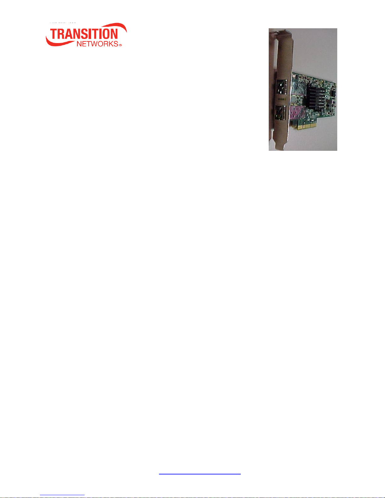
N-TGE-SFP-01
PCIe 2-Port 10GBase-SR/LR SFP+ Fiber NIC
User Guide
High bandwidth 10Gbps or 1Gbps Network Speed
Supports IEEE 802.3x Full-Duplex Flow Control
Compliant with PCIe 2.0 Interface, PCIe 1.1 compatible
Supports Jumbo Frames up to 10 Kbytes
Supports VLAN Tx/Rx acceleration (HW VLAN stripping/insertion)
RoHS compliant
Contents
Cautions and Warnings ......................................................................................................................2
Safety Warnings ........................................................................................................................................ 2
1. Introduction ...................................................................................................................................3
Overview ................................................................................................................................................... 3
Package Contents ..................................................................................................................................... 3
Models / Part Numbers ............................................................................................................................ 3
2. Installation .....................................................................................................................................4
Installing the N-TGE-SFP-01 NIC ............................................................................................................... 4
Downloading and Installing the Driver ..................................................................................................... 6
Additional Driver Information ................................................................................................................ 10
PXE Remote Boot Information ............................................................................................................... 10
SFP/SFP+ Optical Modules ...................................................................................................................... 11
3. LED Indicators .............................................................................................................................. 11
4. Network Parameters .................................................................................................................... 12
5. Technical Specifications ................................................................................................................ 13
Standards ................................................................................................................................................ 13
6. Troubleshooting ........................................................................................................................... 15
Load Balancing and Fail-Over (LBFO) Settings ........................................................................................ 16
7. Warranty and Contact Information ............................................................................................... 17
Warranty ................................................................................................................................................. 17
Contact Us .............................................................................................................................................. 18
8. Compliance Information ............................................................................................................... 19
Declaration of Conformity ...................................................................................................................... 19
Electronic Emission Notices .................................................................................................................... 20
9. Record of Revisions ...................................................................................................................... 20
Appendix A - Windows 7 Throughput Optimization Tips .................................................................... 21
Appendix B - Modify, Repair, Remove, or Uninstall the Driver ........................................................... 25
33623 Rev. B https://www.transition.com/ Page 1 of 31
Page 2

Transition Networks N-TGE-SFP-01 User Guide
Cautions and Warnings
Circuit devices are sensitive to static electricity, which can damage their delicate electronics. Dry
weather conditions or walking across a carpeted floor may cause you to acquire a static electrical charge.
To protect your device, always:
Touch the metal chassis of your computer to ground the static electrical charge before you pick
up the NIC.
Pick up the NIC by holding it on the left and right edges only.
Before installing the N-TGE-SFP-01, ensure that the system meets the hardware and software
requirements listed.
Any PCI slot with the proper configuration is acceptable for connection. If the card is installed in a PCI slot
with fewer lanes than the card requires then the adapter card will not provide the optimum data transfer.
When more than one PCI slot is available make sure to use the PCI slot with the proper configuration.
Safety Warnings
These products are not intended for use in life support products where failure of a product could
reasonably be expected to result in death or personal injury. Anyone using this product in such an
application without express written consent of an officer of Transition Networks does so at their own risk,
and agrees to fully indemnify Transition Networks for any damages that may result from such use or sale.
Installation Instructions: Read all installation instructions before connecting the equipment to the power
source.
Over-temperature: This equipment should not be operated in an area with an ambient temperature
exceeding the maximum recommended.
During Lightning - Electrical Hazard: During periods of lightning activity, do not work on the equipment
or connect or disconnect cables.
Equipment Installation: This equipment should be installed, replaced, or serviced only by trained and
qualified personnel.
Equipment Disposal: Disposal of this equipment should be in accordance to all national laws and
regulations.
Local and National Electrical Codes: This equipment should be installed in compliance with local and
national electrical codes.
33623 Rev. B https://www.transition.com/ Page 2 of 31
Page 3
Transition Networks N-TGE-SFP-01 User Guide
Part Number
Description
N-TGE-SFP-01
PCIe 2-Port 1GBase-X SFP and 10GBase-SR/LR SFP+ Fiber NIC.
1. Introduction
Overview
Transition Networks’ N-TGE-SFP-01 is a 10 Gigabit Ethernet Fiber SFP+ to PCIe x8 bus Network
Interface Card (NIC) that fully complies with IEEE 802.3ae 10GBase-SR/LR and IEEE 802.3z 1GBase-X
standards.
It provides up to 20Gbps full-duplex bandwidth capacity to support high-end servers. It is suitable for data
center, enterprise, SMB, and cloud computing applications.
Package Contents
Before you start installing the PCIe 10GBase-SR/LR Fiber Adapter, verify that the package contains the
following items:
N-TGE-SFP-01 10G NIC
Low Profile Mounting Bracket
Product Documentation Postcard (33504)
The LAN Driver and this User’s Manual are at www.transition.com.
Please notify your sales representative immediately if any of the above items are missing or damaged.
Models / Part Numbers
Note that SFP and SFP+ Modules are sold separately. For Transition Networks SFP/XFP Optical
Transceivers see http://www.transition.com/TransitionNetworks/Landing/SFP-XFP/SFP-XFP.aspx.
33623 Rev. B https://www.transition.com/ Page 3 of 31
Page 4
Transition Networks N-TGE-SFP-01 User Guide
2. Installation
Installing the N-TGE-SFP-01 NIC
The following instructions apply to installing the N-TGE-SFP-01 NIC in most systems. Refer to the
manual(s) supplied with your system for details about performing these tasks on your particular system.
To install the N-TGE-SFP-01 NIC, perform the following steps:
Warning
Before installing the NIC, ensure the system power is OFF and unplugged from the power outlet, and that
proper electrical grounding procedures have been followed.
1. Make sure the power is off before removing the cover.
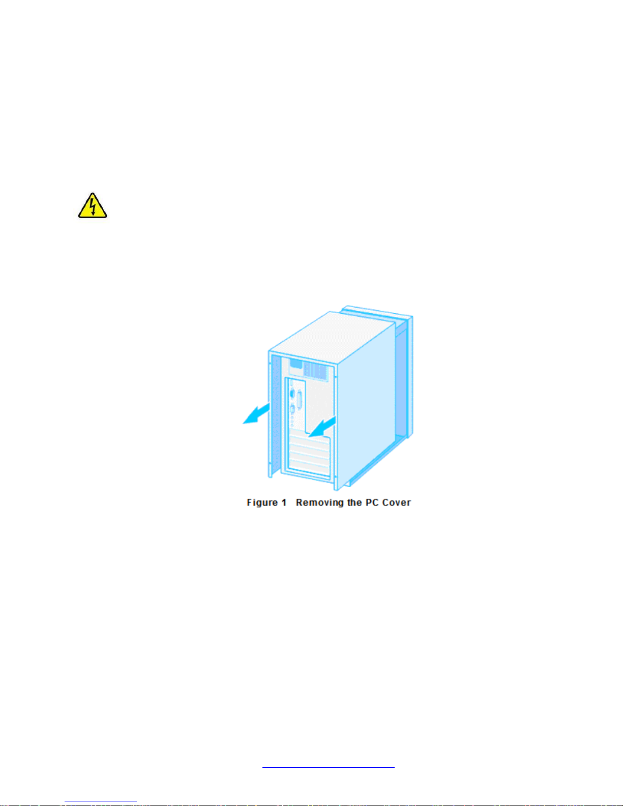
2. Remove the system cover and select any empty PCIe slot. See Figure 1 below.
If you do not know how to identify a PCIe slot, refer to your system documentation.
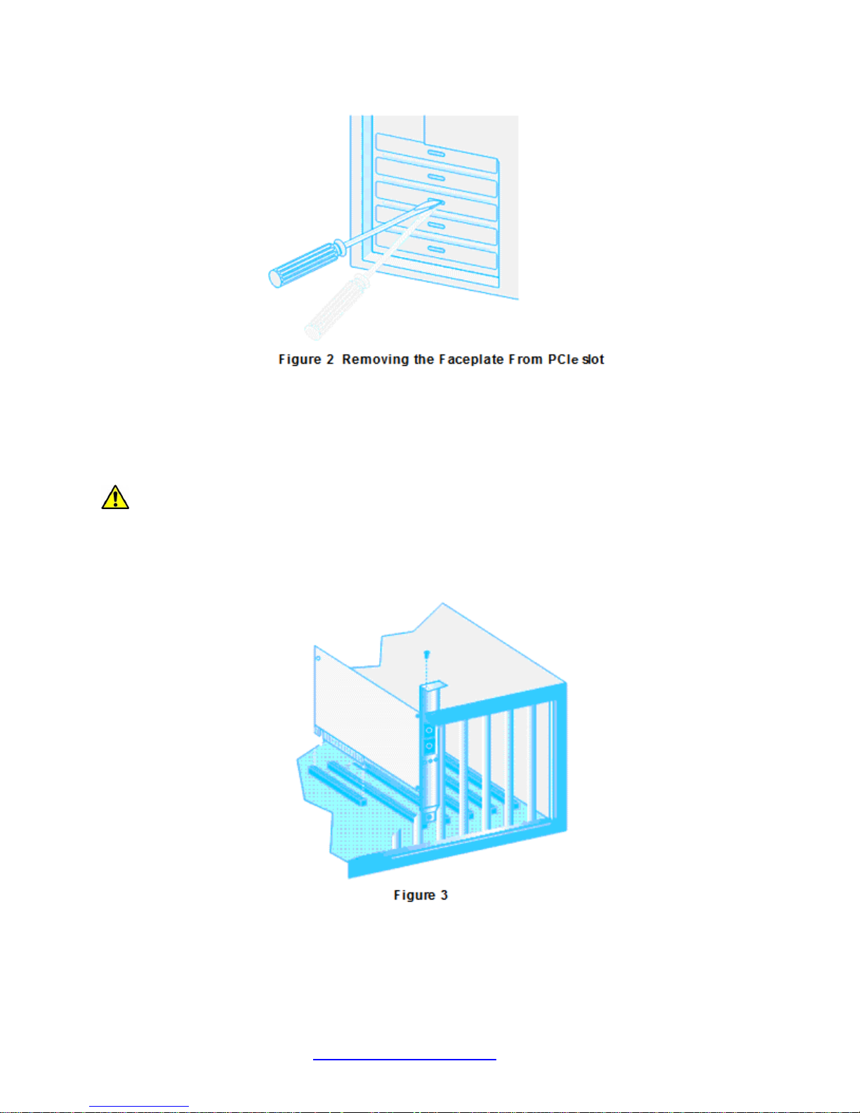
3. Select an empty, non-shared PCIe slot and remove the faceplate. Keep the faceplate in a safe
place. You may need it for future use. See Figure 2 below.
33623 Rev. B https://www.transition.com/ Page 4 of 31
Page 5
Transition Networks N-TGE-SFP-01 User Guide
Note: If you cannot locate or don’t know how to find a PCIe slot, refer to the documentation that came
with your system.
4. Take the N-TGE-SFP-01 NIC from the shipping package and store the packaging material in a
safe location. A Low Profile bracket is includedwith the NIC; install the optional bracket if the
installation device requires it.
Caution
Wear a grounding device and observe electrostatic discharge precautions when installing the NIC in a
system. Failure to observe this caution could result in damage to the NIC.
5. Applying even pressure at both corners of the NIC, push the NIC until it is firmly seated in the
PCIe slot. Make sure the NIC is securely seated. See Figure 3 below.
6. Put the system’s cover back on and fasten it with the screws removed in Step 2 above.
7. Connect the fiber optic cable.
8. Disconnect any personal antistatic devices.
9. Power the system on.
33623 Rev. B https://www.transition.com/ Page 5 of 31
Page 6
Transition Networks N-TGE-SFP-01 User Guide
Downloading and Installing the Driver
After installing the N-TGE-SFP-01 NIC, if the system does not automatically do so, download the driver
from www.transition.com and follow the procedure below.
MLNX_VPI Installation
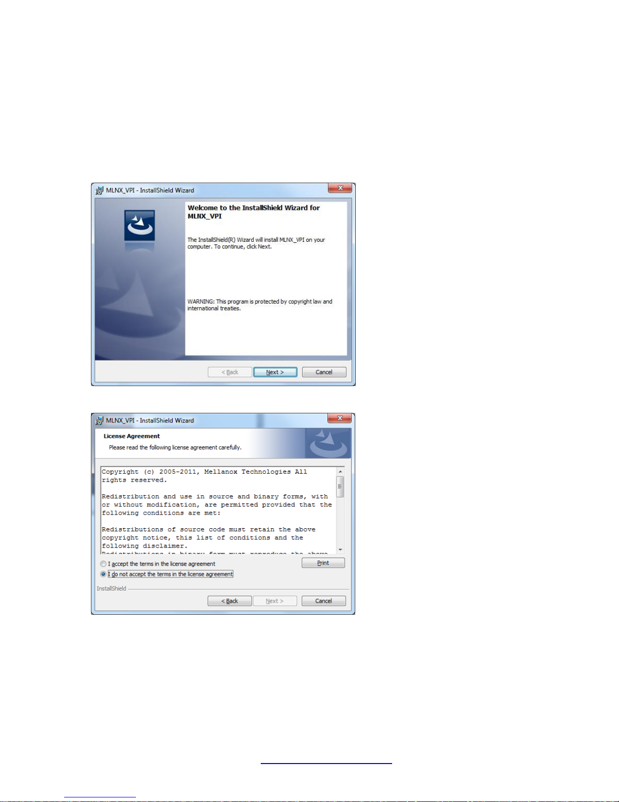
1. At the Driver install location, double click on “MLNX_VPI_WinOF-3_2_0_win7_x64.exe”. The
Preparing to Install... screen displays for a few moments, and then the Welcome screen displays.
2. Click the Next button.
3. Select the “I accept ...” radio button and click Next.
33623 Rev. B https://www.transition.com/ Page 6 of 31
Page 7
Transition Networks N-TGE-SFP-01 User Guide
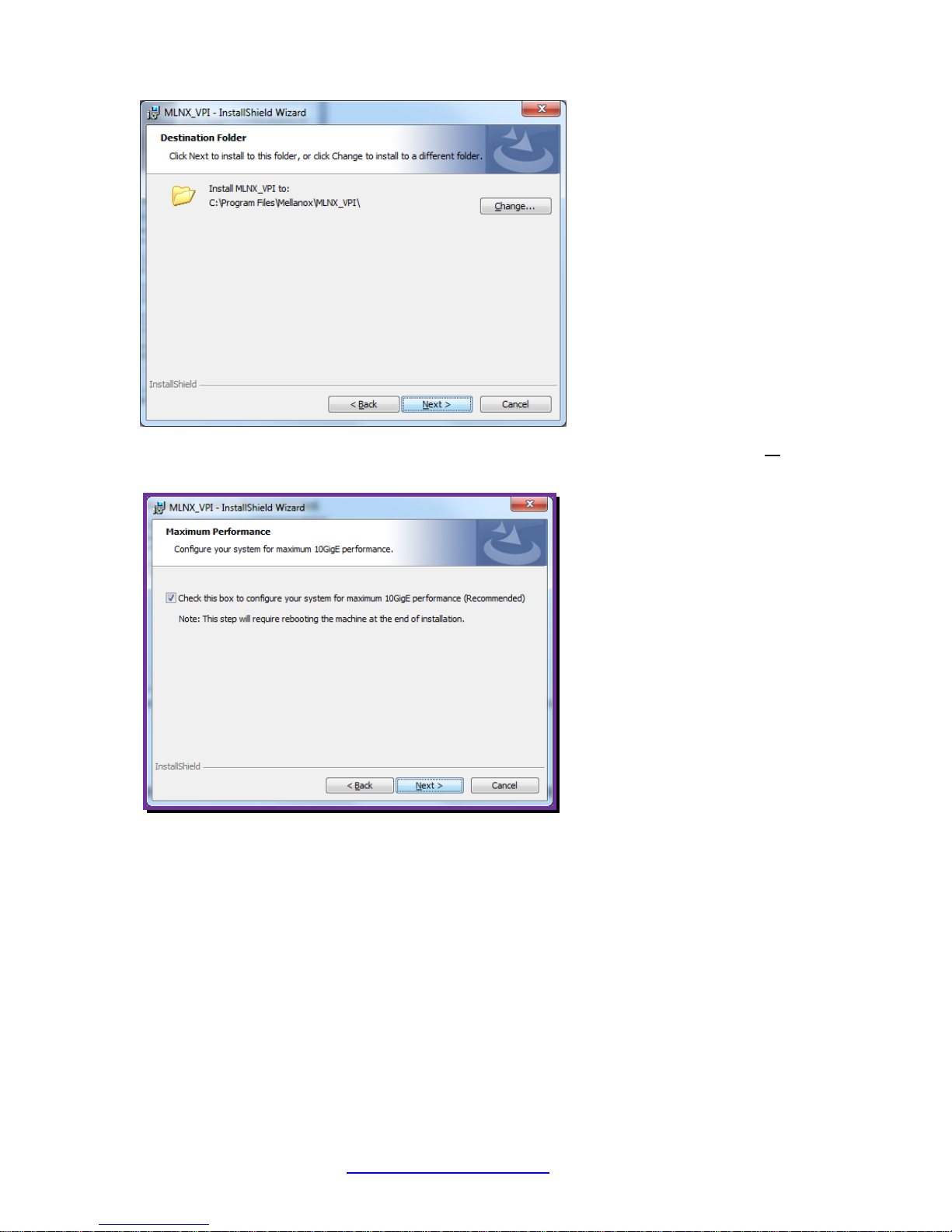
4. Click Next to accept the default Destination folder (C:\Program Files\Mellanox\MLNX_VPI) or click
Change... and navigate to another location and click Next.
5. At the Maximum Performance screen, check or uncheck the box to configure your system for
maximum 10GigE performance (Recommended). Note: If checked, this step will require rebooting the
machine at the end of installation.
6. Click the Next button.
33623 Rev. B https://www.transition.com/ Page 7 of 31
Page 8
Transition Networks N-TGE-SFP-01 User Guide
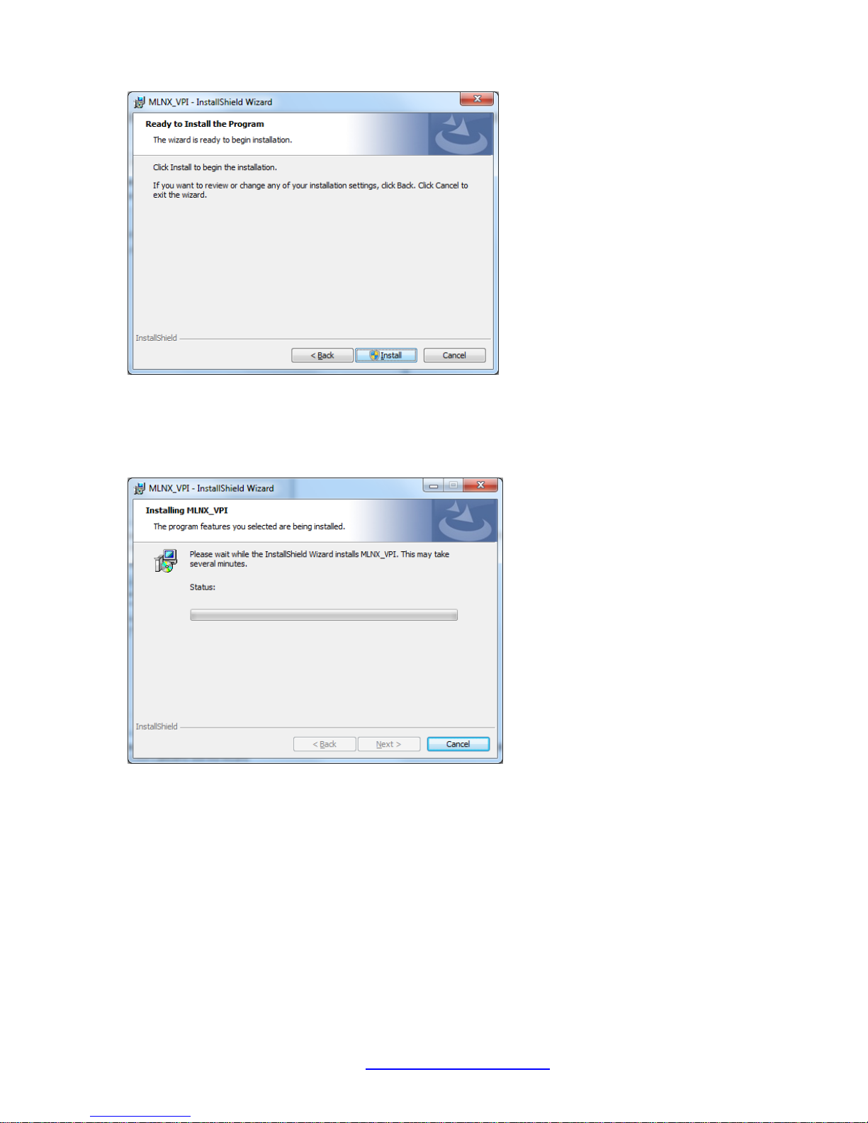
7. At the Ready to Install screen, click the Install button. If you want to review or change any of your
installation settings, click Back. Click Cancel to exit the wizard.
8. If a User Access Control (UAC) screen displays, select Yes. The install process begins and a Status
screen displays.
9. Please wait while the InstallShield Wizard installs MLNX_VPI. This may take several minutes.
33623 Rev. B https://www.transition.com/ Page 8 of 31
Page 9
Transition Networks N-TGE-SFP-01 User Guide
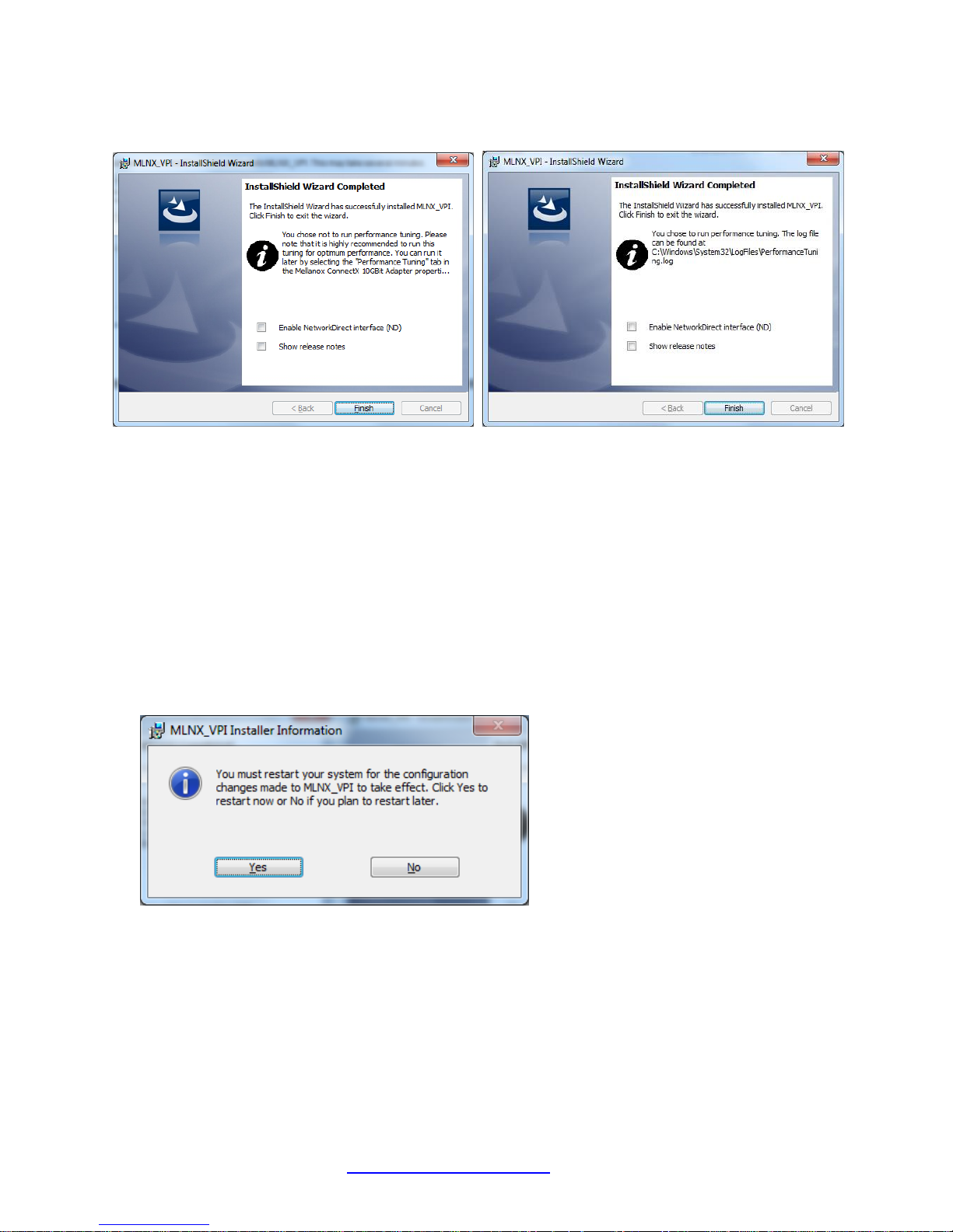
10. An InstallShield Wizard Completed screen displays; the informational note that displays depends on
whether you chose to run performance tuning in step 5 above.
11. At the InstallShield Wizard Completed screen, observe any informational notes and check or uncheck
the displayed options:
□ Enable NetworkDirectinterface (ND)
□ Show release notes
12. Click the Finish button. The Release Notes display if the option was checked in step 11 above.
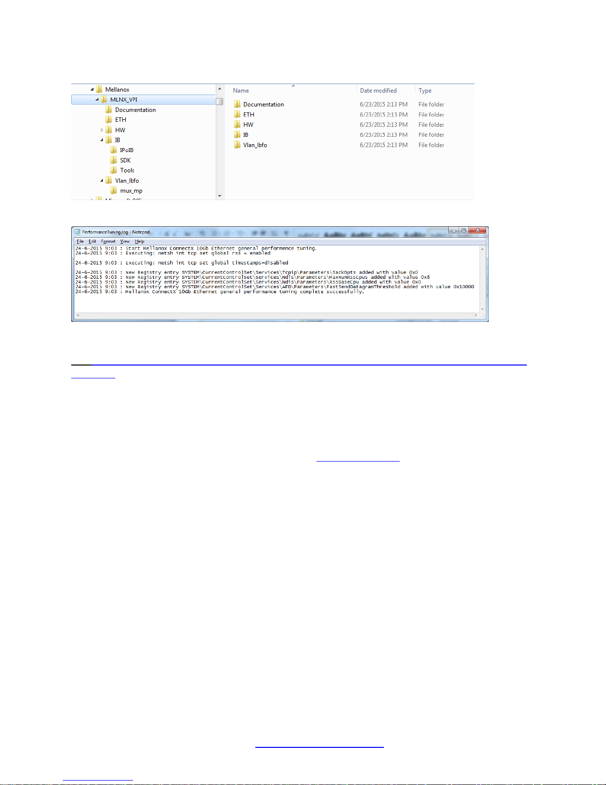
The MLNX_VPI application installs at the Destination folder (e.g., by default at C:\Program
Files\Mellanox\MLNX_VPI) or another location as selected in step 5 above.
The log file can be found at C:\Windows\System32\LogFiles\PerformanceTuning.log.
13. The MLNX_VPI Installer Information dialog displays indicating that “You must restart your system for
the configuration changes made to MLNX_VPI to take effect. Click Yes to restart now or No if you
plan to restart later.”
14. Click Yes to restart now or No if you plan to restart later.
15. Reboot the machine if you unchecked the “10GigE performance (Recommended)” checkbox option in
step 5.
33623 Rev. B https://www.transition.com/ Page 9 of 31
Page 10
Transition Networks N-TGE-SFP-01 User Guide
An example of the install destination folder (C:\Program Files\Mellanox\MLNX_VPI) is shown below
Below is an example of the log file found at C:\Windows\System32\LogFiles\PerformanceTuning.log.
Additional Driver Information
See http://www.mellanox.com/related-docs/prod_software/Mellanox_EN_for_Linux_User_Manual_v2_2-
1_0_1.pdf for the Linux driver manual.
PXE Remote Boot Information
The N-TGE-SFP-01 supports the Mellanox ConnectX® EN PXE solution that enables booting servers
from an IP-based LAN environment. To enable or disable PXE use the MFT tools. To disable, delete the
PXE ROM image from the flash. To enable, place the PXE ROM image to the flash. This software is
based on the open source Etherboot/gPXE project (see www.etherboot.org). For more details go to
www.mellanox.com Products > Ethernet SW/Drivers > ConnectX EN PXE. Mellanox® is a registered
trademark of Mellanox Technologies, Ltd.
33623 Rev. B https://www.transition.com/ Page 10 of 31
Page 11
Transition Networks N-TGE-SFP-01 User Guide
LED
Color
Function
Port 1 LINK
Green
Physical Link; Constant on indicates a good physical link.
Blinking indicates a problem with the Physical link.
Port 1 ACT
Amber
Data Activity; Blinking indicates Data Transfer.
Constant on indicates no Data Transfer.
Port 2 LINK
Green
Physical Link; Constant on indicates a good physical link.
Blinking indicates a problem with the Physical link.
Port 2 ACT
Amber
Data Activity; Blinking indicates Data Transfer.
Constant on indicates no Data Transfer.
SFP/SFP+ Optical Modules
SFP+ transceiver modules can be used to connect fiber optic cables to the NIC card, greatly increasing
the cable reach. Note that the NIC cards are shipped without SFP modules.
Inserting the SFP/SFP+ Module
To insert the module into the cage:
1. Open the module’s locking mechanism.
2. Make sure that the male connectors on the module will align with the female connectors inside of
the cage. Also check that there is no dirt or foreign matter in the module or in the cage.
3. Insert the module into the adapter card module cage.
4. Close the locking mechanism.
Note: If you insert a 1G SFP module in the NIC, you must also use a 1G SFP at the connected
equipment. If you insert a 10G SFP module in the NIC, you must also use a 10G SFP at the connected
equipment.
To remove the module from the cage:
1. Unlock the locking mechanism by opening the handle.
2. Pull the module out of the cage.
3. LED Indicators
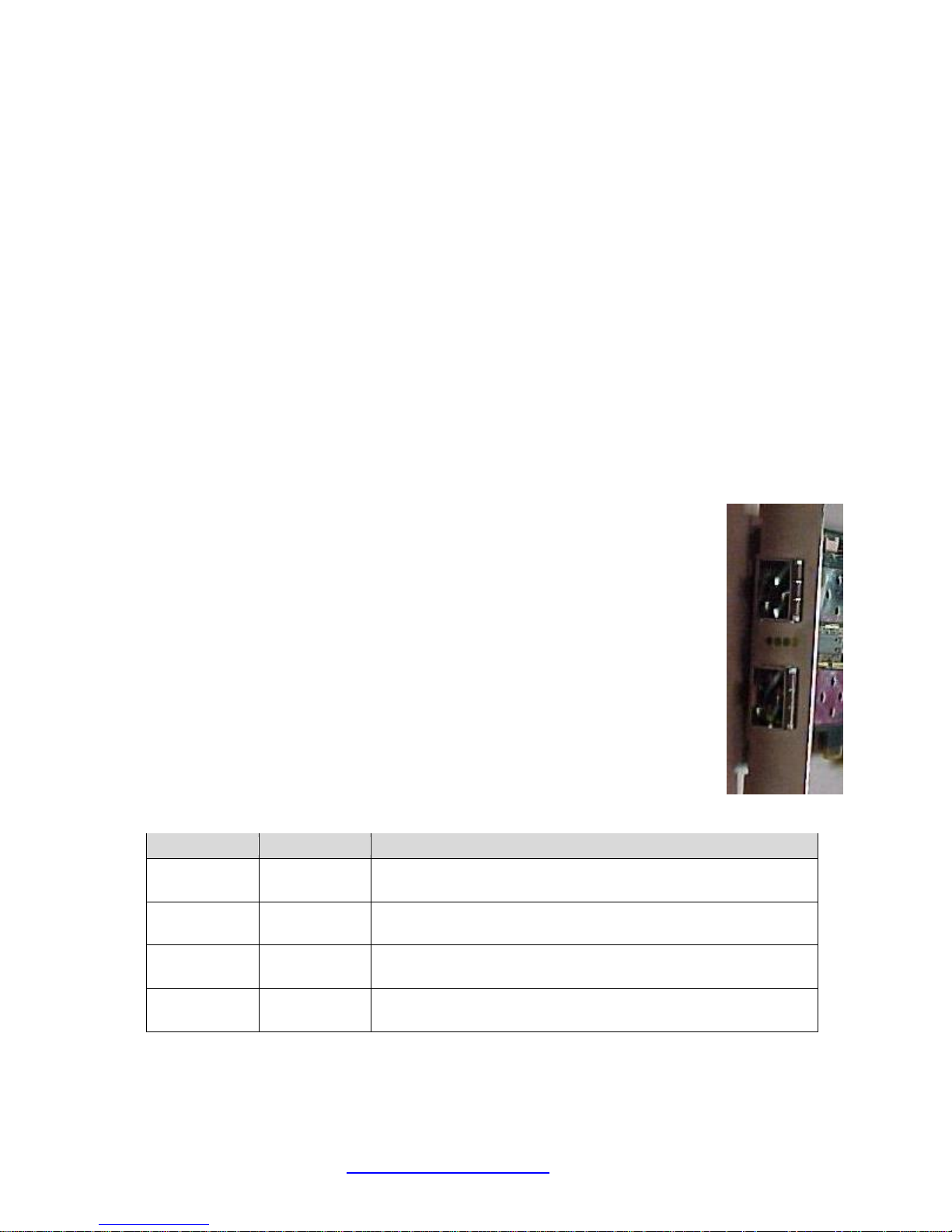
The NIC has two LEDs located on the bracket.
The green LED, when lit, indicates that the driver is running and a valid physical
connection between nodes exists. If the green LED is blinking, it indicates a problem
with the physical link.
The yellow LED when lit, indicates a valid data activity link; this is the logical link.
The yellow LED lights when the network is discovered over the physical link.
A valid data activity link without data transfer is designated by a constant yellow LED
indication.
A valid data activity link with data transfer is designated by a blinking yellow LED
indication.
If the LEDs are not active, either the physical link or the logical link (or both)
connections have not been established.
33623 Rev. B https://www.transition.com/ Page 11 of 31
Page 12

Transition Networks N-TGE-SFP-01 User Guide
Multi-mode Fiber 62.5/125um, 50/125um
10G-SR Full Duplex
850nm (Wavelength)
300m (OM3,50/125μm)
Single-mode Fiber 9/125 um
10G-LR Full Duplex
1310nm or 1550nm
(Wavelength) 10Km
4. Network Parameters
Note: The supported fiber type and transmission distance depend on the SFP/SFP+ module installed in
the NIC’s SFP slot. Note that SFP and SFP+ modules are sold separately.
33623 Rev. B https://www.transition.com/ Page 12 of 31
Page 13

Transition Networks N-TGE-SFP-01 User Guide
5. Technical Specifications
Standards
ETHERNET – IEEE Std 802.3ae 10 Gigabit Ethernet ––IEEE Std 802.3ak 10GBASE-CX4 ––IEEE Std
802.3ap Backplanes, including FEC ––IEEE Std 802.3ad Link Aggregation and Failover ––IEEE Std
802.1Q VLAN tags, .1p Priorities ––IEEE P802.1au D2.0 Congestion Notification ––IEEE P802.1az D0.2
Enhanced Transmission Selection ––IEEE P802.1bb D1.0 Priority-based Flow Control ––Jumbo frame
support (10KB) ––128 MAC/VLAN addresses per port – IEEE Std 802.3z 1 Gigabit Ethernet
TCP/UDP/IP STATELESS OFFLOAD ––TCP/UDP/IP checksum offload ––TCP Large Send (< 64KB) or
Giant Send (64KB-16MB) Offload for segmentation ––Receive Side Scaling (RSS) up to 32 queues ––
Line rate packet filtering
ADDITIONAL CPU OFFLOADS ––RDMA over Converged Ethernet ––FC checksup offload ––VMDirect
Path support ––Traffic steering across multiple cores ––Intelligent interrupt coalescence ––Compliant to
Microsoft RSS and NetDMA
HARDWARE-BASED I/O VIRTUALIZATION ––Single-Root IOV ––Address translation and protection ––
Dedicated adapter resources and guaranteed isolation ––Multiple queues per virtual machine ––
Hardware switching between guest OSs ––Enhanced QoS for vNICs ––VMware NetQueue Support
STORAGE SUPPORT ––T11.3 FC-BB-5 FCoE
Fiber Optic Cable
□ 62.5/125, 50/125m multi-mode
□ 9/125m single-mode
Data Transfer Mode/Speed
□ Full duplex (Default)
□ 10Gbps speed (14,880,000 pps)
□ 1Gbps speed (1,190,476 pps)
Diagnostics LEDs on Bracket
□ Port 1 LNK, Port 1 ACT
□ Port 2 LNK, Port 2 ACT
OS Support
RedHat Enterprise Linux v5, VMware ESXi 4.0 Server, Windows Server 2003 (Service Pack 2) or
Server 2003 R2, Windows 2008 Server, Windows 7 64-bit, XenServer 5.6.
33623 Rev. B https://www.transition.com/ Page 13 of 31
Page 14

Transition Networks N-TGE-SFP-01 User Guide
Bus Slot
PCIe 2.0 Compliant; PCIe 1.1 compatible;
Fits x8 or x16 slots
PCI Express Interface
2.5GT/s or 5.0GT/s link rate x8 (20+20GB/s or 40+40Gb/s
bidirectional bandwidth
SFP+ module power
dissipation
Up to 1.0 W (Power Level I module)
Ambient Temperature
0° to 50° C
Operating Temperature
0° to 40° C
Humidity
5% to 90%
Emissions
Complies with EMI Standard
FCC Class B
CE Mark
Dimensions
168 mm (L) x 64 mm (H);
6.61 inches (L) x 2.52 inches (H)
Weight
0.07 Kg (2.47 Oz.)
Warranty
Lifetime
Specifications
33623 Rev. B https://www.transition.com/ Page 14 of 31
Page 15

Transition Networks N-TGE-SFP-01 User Guide
6. Troubleshooting
If the N-TGE-SFP-01 NIC fails, isolate and correct the fault by determining the answers to the following
questions and then taking the indicated action:
1. Verify that section 5. Technical Specifications (page 13) are met.
2. Verify that section 2. Installation instructions on page 4 were followed.
3. Is the green LINK LED lit indicating link up?
NO
• Ensure the switch port is not down.
• Remove the failed adapter and reboot the system.
• Reseat the NIC in its PCI slot or insert the NIC in a different PCI slot.
• If the PCI slot is known to be functional, replace the adapter.
• Contact Tech Support. See Contact Us on page 18.
YES
• Proceed to step 4.
4. Is the amber ACT LED blinking indicating traffic is present?
NO
• Check the cables for proper connection.
• Ensure that the cable is connected on both ends or use a known working cable
• If there is port activity, disconnect / reconnect the cable to restart the initialization process.
• Restart the workstation to restart the initialization process.
• Contact Tech Support. See Contact Us on page 18.
5. Check the log file found at C:\Windows\System32\LogFiles\PerformanceTuning.log. For example:
24-6-2015 9:03 : Start Mellanox ConnectX 10Gb Ethernet general performence tuning.
24-6-2015 9:03 : Executing: netsh int tcp set global rss = enabled
24-6-2015 9:03 : Executing: netsh int tcp set global timestamps=disabled
24-6-2015 9:03 : New Registry entry SYSTEM\CurrentControlSet\Services\Tcpip\Parameters\SackOpts added with
value 0x0
24-6-2015 9:03 : New Registry entry SYSTEM\CurrentControlSet\Services\Ndis\Parameters\MaxNumRssCpus added
with value 0x8
24-6-2015 9:03 : New Registry entry SYSTEM\CurrentControlSet\Services\Ndis\Parameters\RssBaseCpu added
with value 0x0
24-6-2015 9:03 : New Registry entry
SYSTEM\CurrentControlSet\Services\AFD\Parameters\FastSendDatagramThreshold added with value 0x10000
24-6-2015 9:03 : Mellanox ConnectX 10Gb Ethernet general performance tuning complete successfully.
5. Check theRelease Notes for new features, changes, and known issues at C:\Program
Files\Mellanox\MLNX_VPI\Documentation by default.
33623 Rev. B https://www.transition.com/ Page 15 of 31
Page 16
Transition Networks N-TGE-SFP-01 User Guide
Load Balancing and Fail-Over (LBFO) Settings
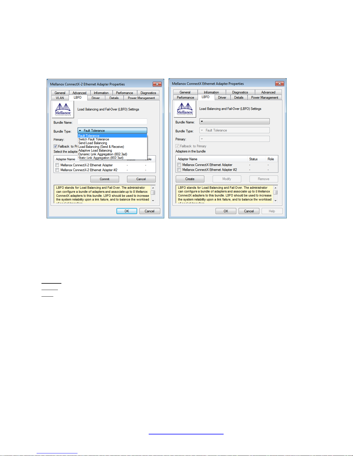
Load Balancing and Fail Over (LBFO) lets an administrator configure a ‘bundle’ of adapters and associate
up to eight adapters to this bundle. LBFO should be used to increase the system reliability upon a link
failure, and to balance the workload of packet transfers.
The following LBFO types are supported:
Fault Tolerance - provides redundancy through automatic fail-over from an active adapter to a standby
adapter in case of switch port, cable, or adapter failure.
Send Load Balancing - provides transmit traffic load balancing and fault tolerance in the event of switch
port, cable, or adapter failure. In this mode, the transmit traffic is balanced across member adapters
based on the source and destination nodes. Note that only one adapter accepts all receive traffic.
Team attributes
Primary: Sets the designated primary adapter of the team.
Status: Shows the status of the specific adapter. Values are Connected, Disconnected, Disabled.
Role: Shows the current role of the adapter in the team. Values are: Active and Backup.
Note: The N-TGE-SFP-01 uses an IC manufactured by Mellanox.
Only Mellanox-based ConnectX Mellanox adapters can be part of the bundle.
The bundle can contain up to eight Mellanox-based ConnectX adapters.
All the adapters in the bundle must have the same RSS, MTU, Offloading options, and LBFO type.
If you attempt to add or modify an adapter with non-compatible properties, this adapter will be
removed from the bundle and an event log will be issued.
With the Primary adapter disconnected, a different adapter may takethe Active role.
33623 Rev. B https://www.transition.com/ Page 16 of 31
Page 17

Transition Networks N-TGE-SFP-01 User Guide
7. Warranty and Contact Information
Warranty
Limited Lifetime Warranty
Effective for Products Shipped May 1, 1999 and After. Every Transition Networks labeled product
purchased after May 1, 1999, and not covered by a fixed-duration warranty will be free from defects in
material and workmanship for its lifetime. This warranty covers the original user only and is not
transferable.
This warranty does not cover damage from accident, acts of God, neglect, contamination, misuse or
abnormal conditions of operation or handling, including over-voltage failures caused by use outside of the
product's specified rating, or normal wear and tear of mechanical components. If the user is unsure about
the proper means of installing or using the equipment, contact Transition Networks free technical support
services.
Transition Networks will, at its option:
• Repair the defective product to functional specification at no charge
• Replace the product with an equivalent functional product
• Refund a portion of purchase price based on a depreciated value
Return Authorization
To return a defective product for warranty coverage, contact Transition Networks's technical support
department for a return authorization number. See Contact Us below for ways to contact Transition
Networks’ technical support department.
Return Instructions
Send the defective product postage and insurance prepaid to the following address:
Transition Networks, Inc.
10900 Red Circle Drive
Minnetonka, MN 55343 USA
Attn: RETURNS DEPT: CRA/RMA # ___________
Failure to properly protect the product during shipping may void this warranty. The return authorization
number must be written on the outside of the carton to ensure its acceptance. We cannot accept delivery
of any equipment that is sent to us without a CRA or RMA number.
CRA’s are valid for 60 days from the date of issuance. An invoice will be generated for payment on any
unit(s) not returned within 60 days.
Upon completion of a demo/ evaluation test period, units must be returned or purchased within 30 days.
An invoice will be generated for payment on any unit(s) not returned within 30 days after the demo/
evaluation period has expired.
The customer must pay for the non-compliant product(s) return transportation costs to Transition
Networks for evaluation of said product(s) for repair or replacement. Transition Networks will pay for the
shipping of the repaired or replaced in-warranty product(s) back to the customer (any and all customs
charges, tariffs, or/and taxes are the customer's responsibility).
Before making any non-warranty repair, Transition Networks requires a $200.00 charge plus actual
shipping costs to and from the customer. If the repair is greater than $200.00, an estimate is issued to the
customer for authorization of repair. If no authorization is obtained, or the product is deemed ‘not
repairable’, Transition Networks will retain the $200.00 service charge and return the product to the
customer not repaired. Non-warranted products that are repaired by Transition Networks for a fee will
carry a 180-day limited warranty. All warranty claims are subject to the restrictions and conventions set
forth by this document.
Transition Networks reserves the right to charge for all testing and shipping incurred, if after testing, a
return is classified as "No Problem Found."
33623 Rev. B https://www.transition.com/ Page 17 of 31
Page 18

Transition Networks N-TGE-SFP-01 User Guide
THIS WARRANTY IS YOUR ONLY REMEDY. NO OTHER WARRANTIES, SUCH AS FITNESS FOR A
PARTICULAR PURPOSE, ARE EXPRESSED OR IMPLIED. TRANSITION NETWORKS IS NOT LIABLE
FOR ANY SPECIAL, INDIRECT, INCIDENTAL OR CONSEQUENTIAL DAMAGES OR LOSSES,
INCLUDING LOSS OF DATA, ARISING FROM ANY CAUSE OR THEORY. AUTHORIZED RESELLERS
ARE NOT AUTHORIZED TO EXTEND ANY DIFFERENT WARRANTY ON TRANSITION NETWORKS'S
BEHALF.
Contact Us
Technical support
Technical support is available 24-hours a day
US and Canada: 1-800-260-1312
International: 00-1-952-941-7600
Transition now
Chat live via the Web with Transition Networks Technical Support.
Log onto www.transition.com and click the Transition Now link.
Web-based seminars
Transition Networks provides seminars via live web-based training.
Log onto www.transition.com and click the Learning Center link.
E-Mail
Ask a question anytime by sending an e-mail to our technical support staff.
Address
Transition Networks
10900 Red Circle Drive
Minnetonka, MN 55343, U.S.A.
Telephone: 952-941-7600
Toll free: 800-526-9267
Fax: 952-941-2322
33623 Rev. B https://www.transition.com/ Page 18 of 31
Page 19

Transition Networks N-TGE-SFP-01 User Guide
8. Compliance Information
Declaration of Conformity
33623 Rev. B https://www.transition.com/ Page 19 of 31
Page 20
Transition Networks N-TGE-SFP-01 User Guide
EMI
EN55022:2006
EN61000-3-2:2000
EN61000-3-3:1995+A1/2001+A2/2005
EN61000-6-3:2001
EMS
EN55024/1998+A1:2001+A2:2003
EN61000-4-2:2001
EN61000-4-3:2002+A1:2002
EN61000-4-4:2004
EN61000-4-5:2001
EN61000-4-6:2003
EN61000-4-11:2001
Rev
Date
Notes
A
6/26/15
Manual released for N-TGE-SFP-01.
B
1/22/18
Update information on PXE remote boot, contact, and 1Gbps SFP.
Electronic Emission Notices
Federal Communications Commission (FCC) Statement
This equipment has been tested and found to comply with the FCC Part 15, Subpart B, Class B.
CISPR 22:A1:2000+A2:2002;ICES-003:2004, Class B
European Community (CE) Electromagnetic Compatibility Directive
This equipment has been tested and found to comply with the protection requirements of European
Emission Standard EN55022 and EN55024.
9. Record of Revisions
Trademarks
All trademarks and registered trademarks are the property of their respective owners.
Copyright restrictions
© 2015-2018 Transition Networks. All rights reserved. No part of this work may be reproduced or used in any form or
by any means - graphic, electronic or mechanical - without written permission from Transition Networks.
33623 Rev. B https://www.transition.com/ Page 20 of 31
Page 21
Transition Networks N-TGE-SFP-01 User Guide
Appendix A - Windows 7 Throughput Optimization Tips
When used in Windows 7, the default settings for a 10Gb NIC may result in throughput that is lower than
desired. The reduced throughput is often due to bottlenecks within Windows, and not necessarily a
limitation of the 10Gb NIC. In a test bed using Desktop PCs that utilize 2nd generation i5 processors, and
the program NTtTCP to measure TCP performance, we observed good TX throughput and not-so-good
RX throughput. This section reveals NIC parameters that can be adjusted to compensate for the Windows
bottlenecks and improve throughput on a Transition Networks N-TGE-SFP-01 10Gb NIC:
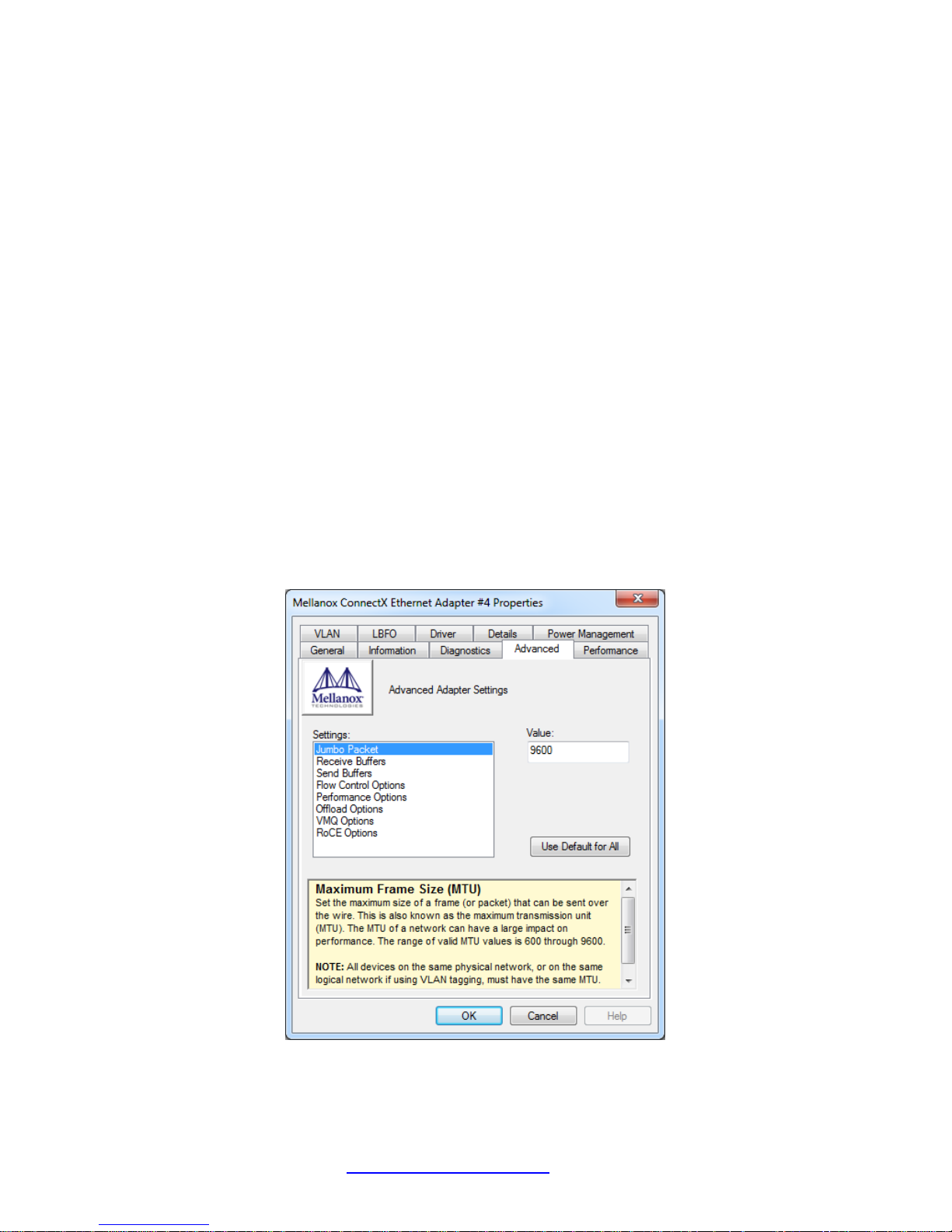
1. Use Jumbo Frames. Increasing the MTU from 1500 to 9600 will have a two-fold effect in
current Windows 7 desktops. Most importantly, it greatly reduces the frames per second required to
achieve line-rate during data transfer, which in-turn reduces the Desktop PC’s resource requirements
during large data transfers. Data transfers that are CPU bound at the default MTU will benefit greatly
from using Jumbo Frames. Additionally, using 9K Jumbo Frames will increase the max theoretical
payload throughput from 9.4Gbps to 9.9Gbps.
Using commodity desktop PCs with 4th Generation i5 processors, we have observed data receive rates
that peaked in the 3-5Gbps range, when all NIC settings were at defaults. Changing the Jumbo Packet
setting from 1500 to 9600 increased the data transfer throughput to 8+Gbps on these PCs.
To change the max MTU, navigate to:
Control Panel Network and Internet Network and Sharing Center Change Adapter Settings
Local Area Connection ‘X’ Properties Configure Advanced Tab Jumbo Packet
33623 Rev. B https://www.transition.com/ Page 21 of 31
Page 22
Transition Networks N-TGE-SFP-01 User Guide
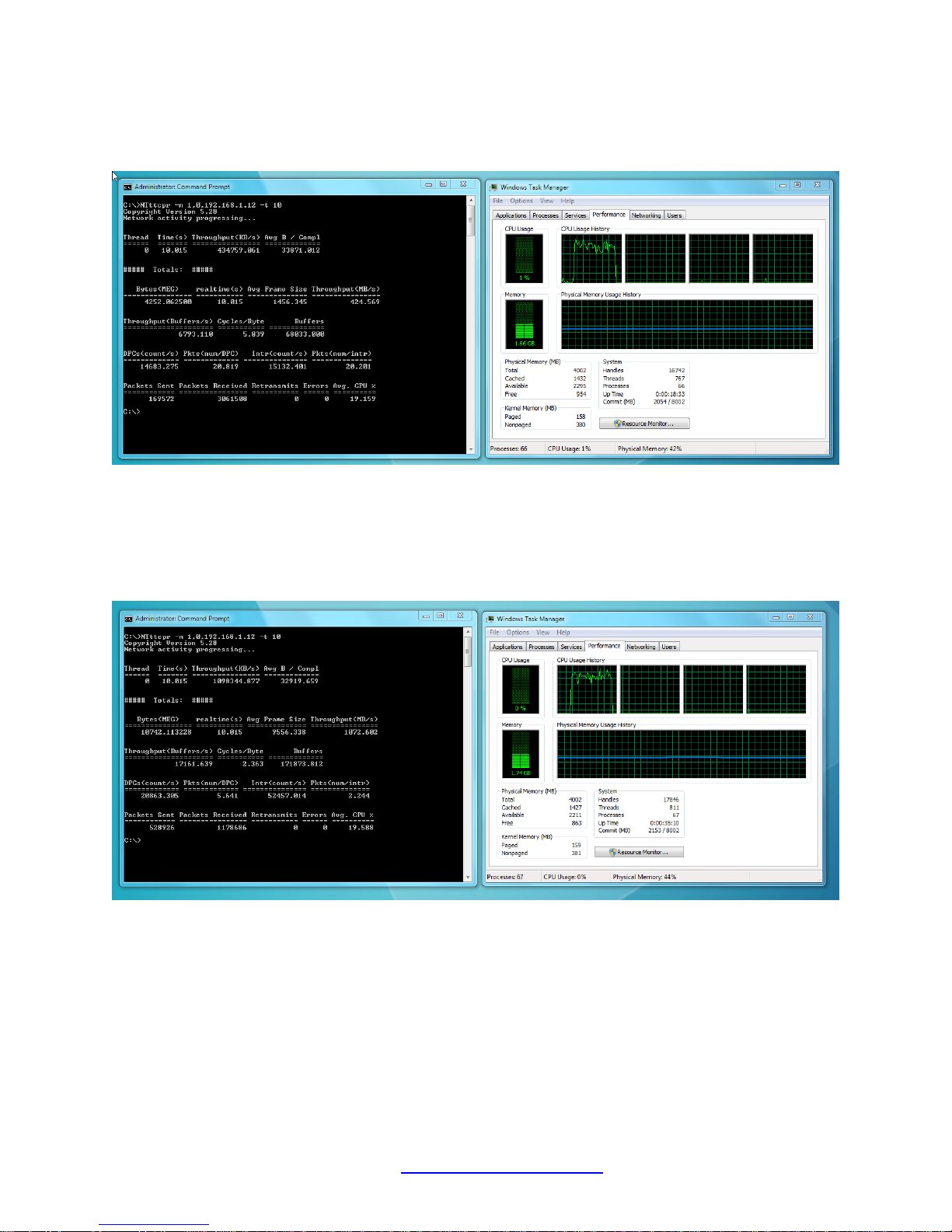
Baseline NTtTCP example 1- All NIC settings at default:
424MB/s (3.39Gbps receive throughput, consuming most of one CPU core)
All NIC settings at default except Jumbo Frames set to 9600:
1072MB/s (8.57Gbps receive throughput, with comparable CPU consumption)
33623 Rev. B https://www.transition.com/ Page 22 of 31
Page 23
Transition Networks N-TGE-SFP-01 User Guide
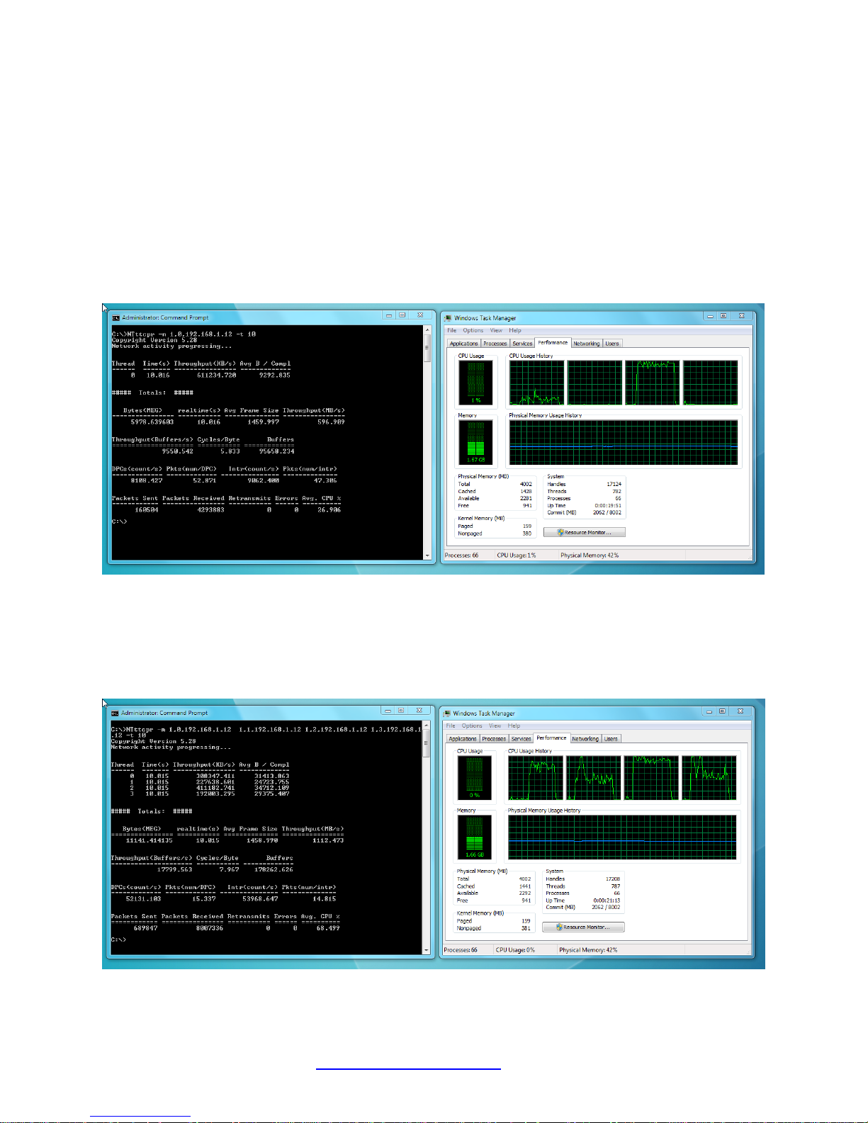
2. Use multithreaded applications for data transfer
Receiving data at 10Gbps in a Windows 7 environment is CPU intensive, even when offloading is
enabled. Spreading that work across multiple CPU cores can reduce the possibility of the application
becoming CPU bound, and increase the throughput during data transfer.
Using the same i5 Desktop PCs, as the Jumbo Frame tests, we can see the performance differences
between using single-threaded and multi-threaded data transfer applications.
Baseline 2 - Single threaded NTtTCP example:
596MB/s (4.77Gbps of payload throughput, with 26.9% CPU utilization)
Multi threaded NTtTCP example:
1112MB/s (8.90Gbps throughput and 68.5% CPU utilization)
33623 Rev. B https://www.transition.com/ Page 23 of 31
Page 24
Transition Networks N-TGE-SFP-01 User Guide
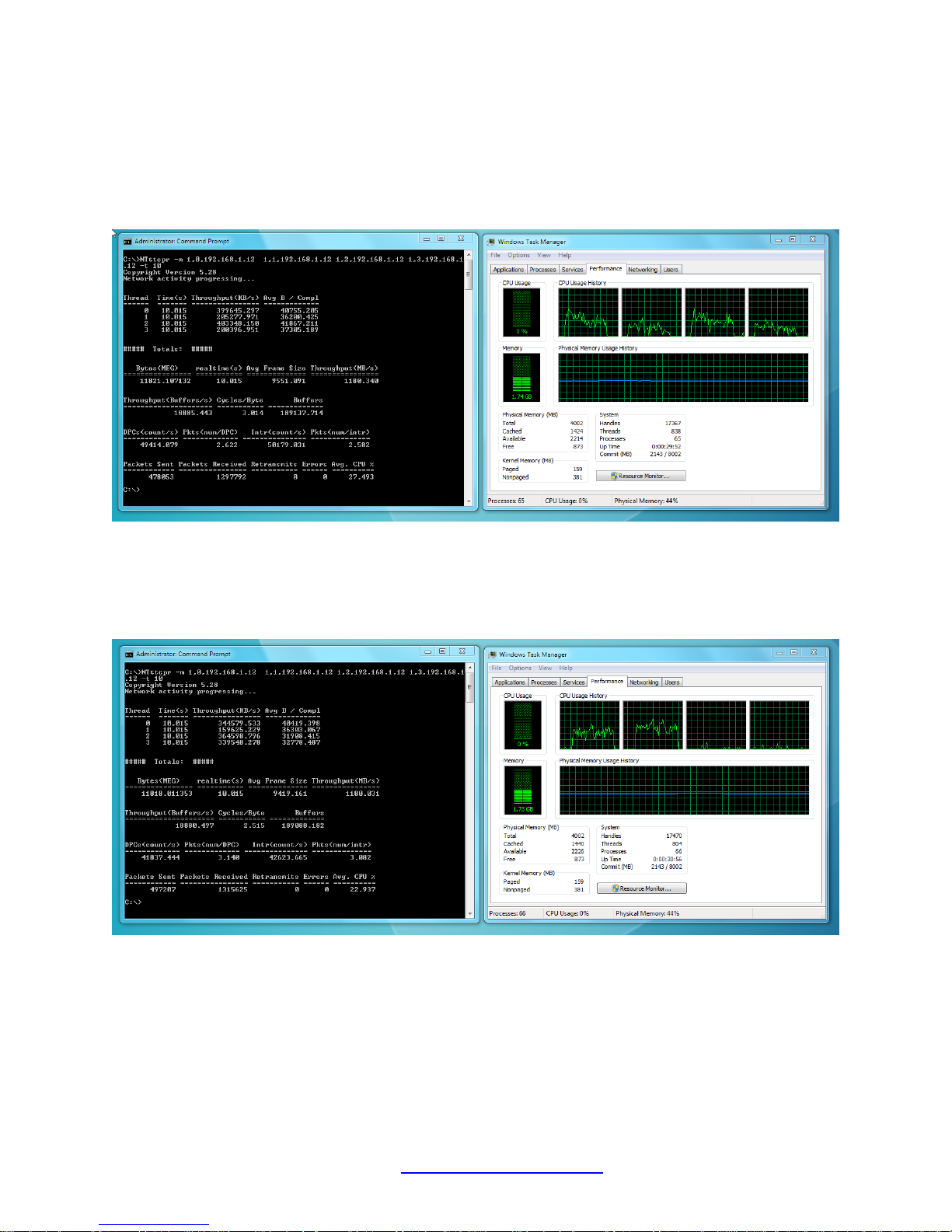
3. Combine Jumbo Frames and Multithreading to maximize throughput
while minimizing CPU utilization
Multithreaded Application + Jumbo Frames example 1:
1180MB/s (9.40Gbps of payload throughput and 27.5% CPU utilization)
Multithreaded Application + Jumbo Frames example 2:
1180MB/s (9.40Gbps of payload throughput and 22.9% CPU utilization)
33623 Rev. B https://www.transition.com/ Page 24 of 31
Page 25
Transition Networks N-TGE-SFP-01 User Guide
Appendix B - Modify, Repair, Remove, or Uninstall the Driver
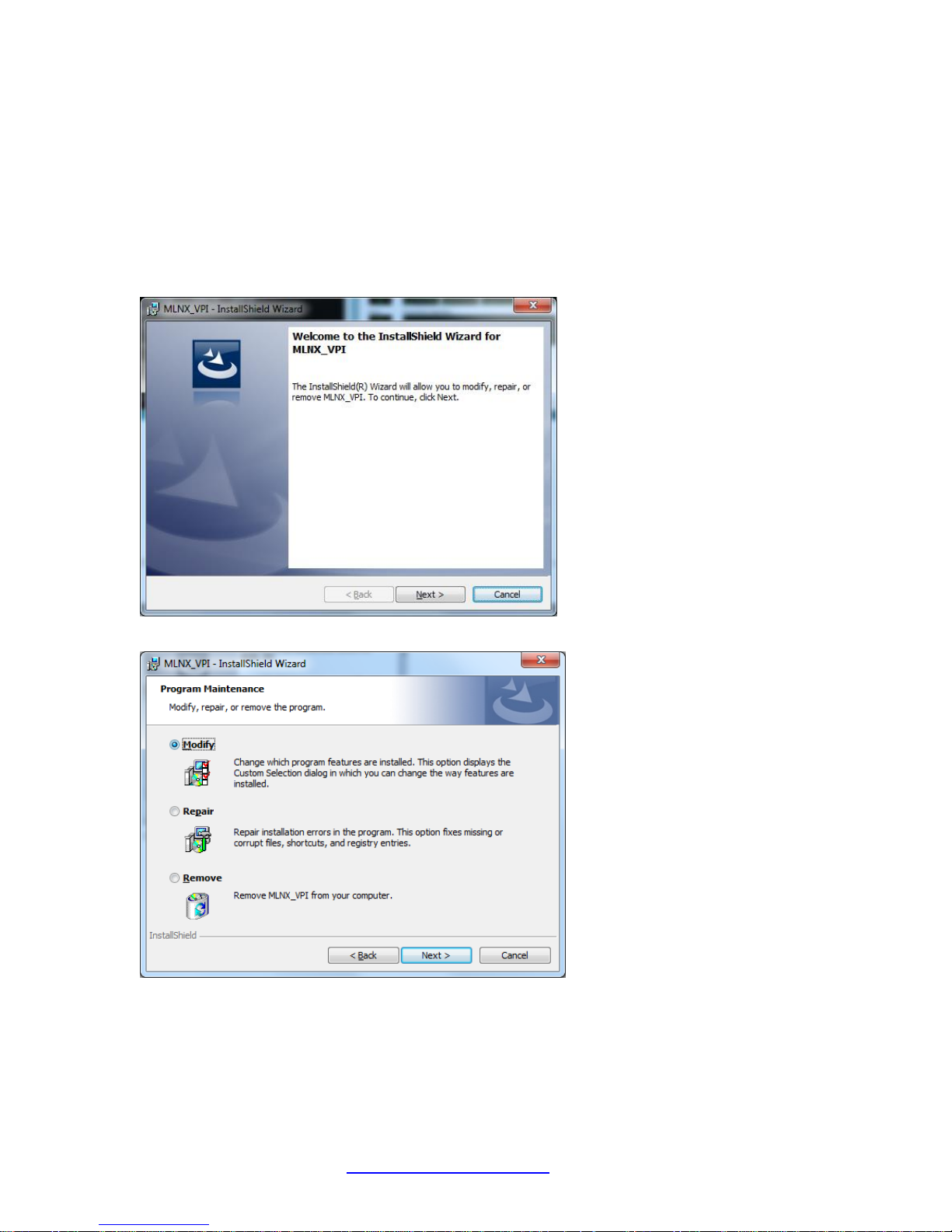
After you have installed the driver, you can then modify, repair, or remove the driver using the following
Program Maintainence procedures.
Modify the Installed Driver
The Modify Program Maintainance option lets you change which program features are installed. This
option displays the Custom Selection dialog in which you can change the way features are installed.
1. Double click on the “MLNX_VPI_WinOF-3_2_0_win7_x64.exe” file.
2. Click the Next button.
3. Select the Modify radio button and click Next.
33623 Rev. B https://www.transition.com/ Page 25 of 31
Page 26
Transition Networks N-TGE-SFP-01 User Guide
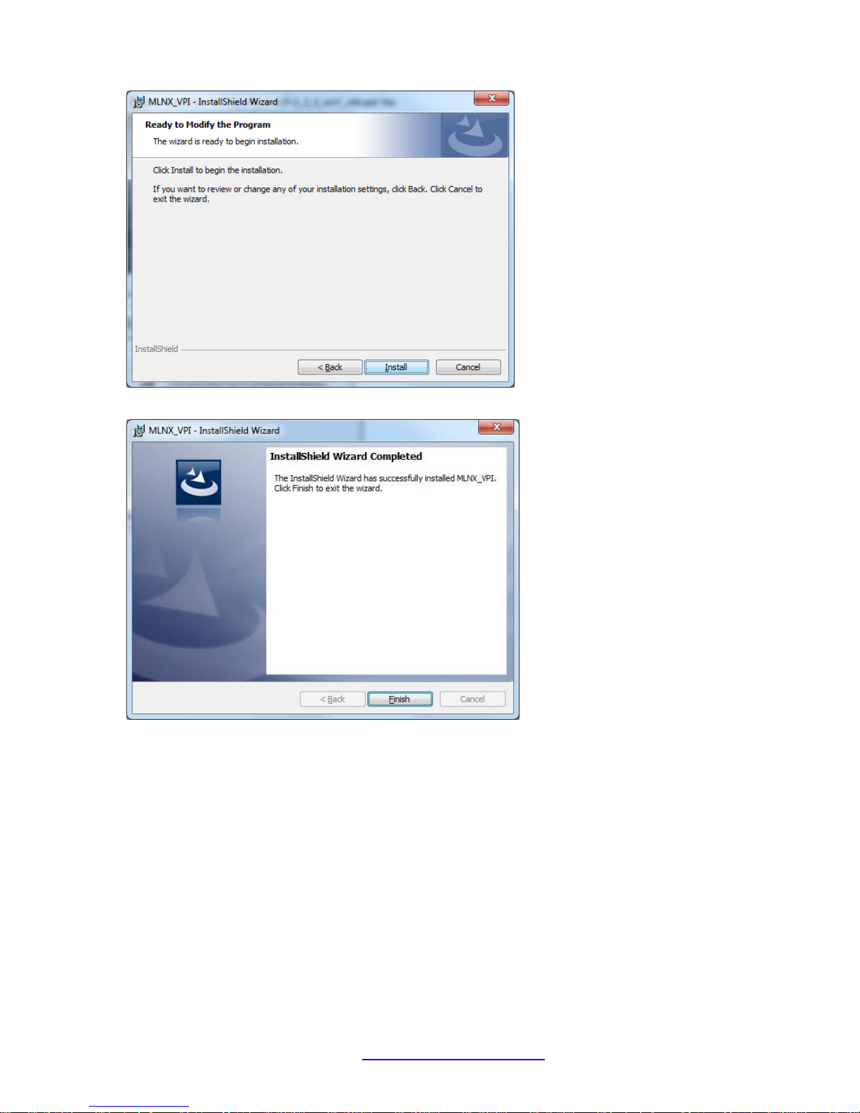
4. Click Install to begin to modify the installation. If a UAC screen displays, click Yes to continue.
5. When the Wizard Completed screen displays, click the Finish button. The modify procedure is
complete.
33623 Rev. B https://www.transition.com/ Page 26 of 31
Page 27
Transition Networks N-TGE-SFP-01 User Guide
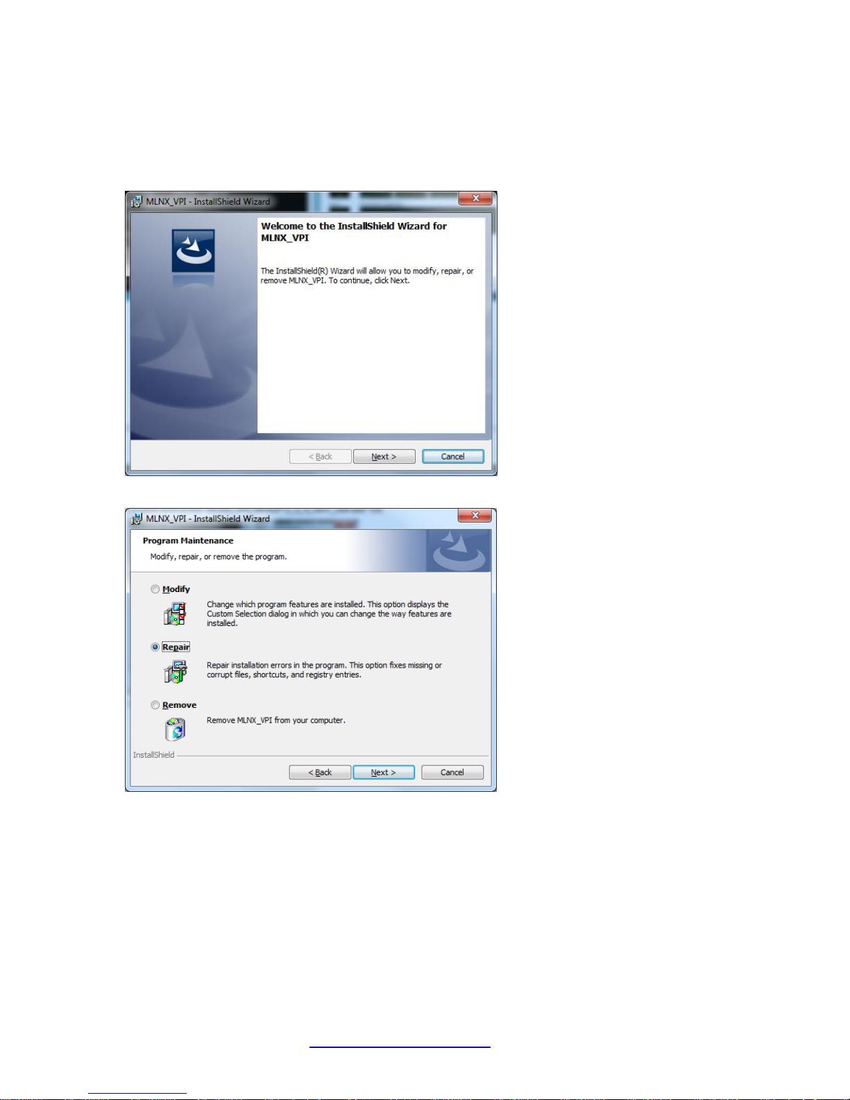
Repair the Installed Driver
The Repair Program Maintainance option repairs installation errors in the program. This option fixes
missing or corrupt files, shortcuts, and registry entries.
1. Double click on the “MLNX_VPI_WinOF-3_2_0_win7_x64.exe” file.
2. Click the Next button.
3. Select the Repair radio button and click Next.
33623 Rev. B https://www.transition.com/ Page 27 of 31
Page 28
Transition Networks N-TGE-SFP-01 User Guide
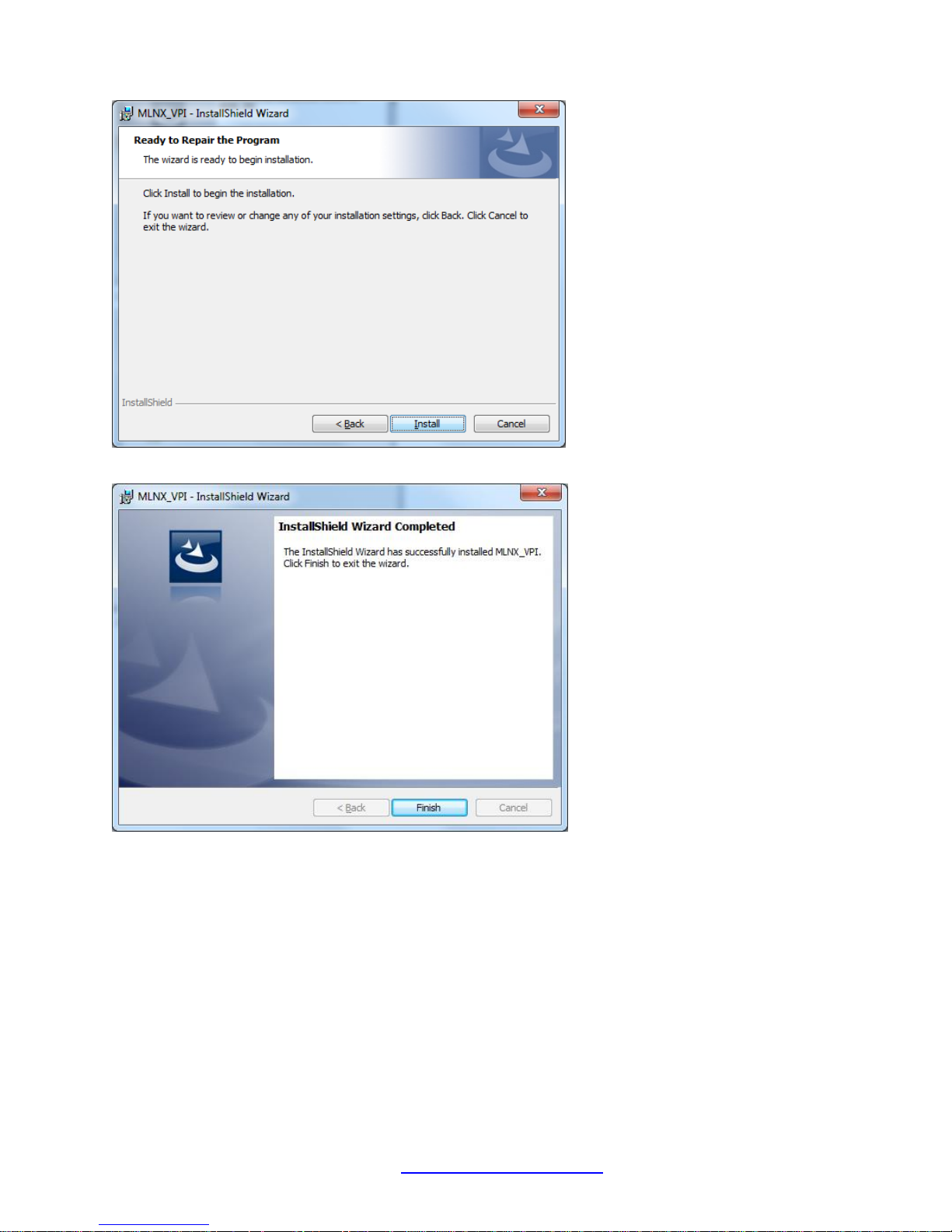
4. Click the Install button to begin.
5. When the Wizard Completed screen displays, click the Finish button. The repair procedure is
complete.
33623 Rev. B https://www.transition.com/ Page 28 of 31
Page 29
Transition Networks N-TGE-SFP-01 User Guide
Remove the Installed Driver
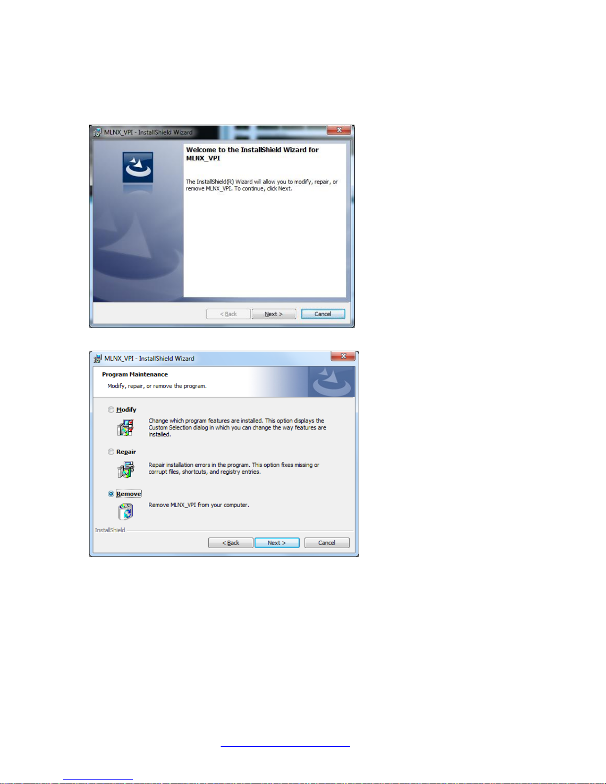
The Remove Program Maintainance option removes the MLNX_VPI driver from your computer.
1. Double click on the “MLNX_VPI_WinOF-3_2_0_win7_x64.exe” file.
2. Click the Next button.
3. Select the Remove radio button and click Next.
33623 Rev. B https://www.transition.com/ Page 29 of 31
Page 30
Transition Networks N-TGE-SFP-01 User Guide
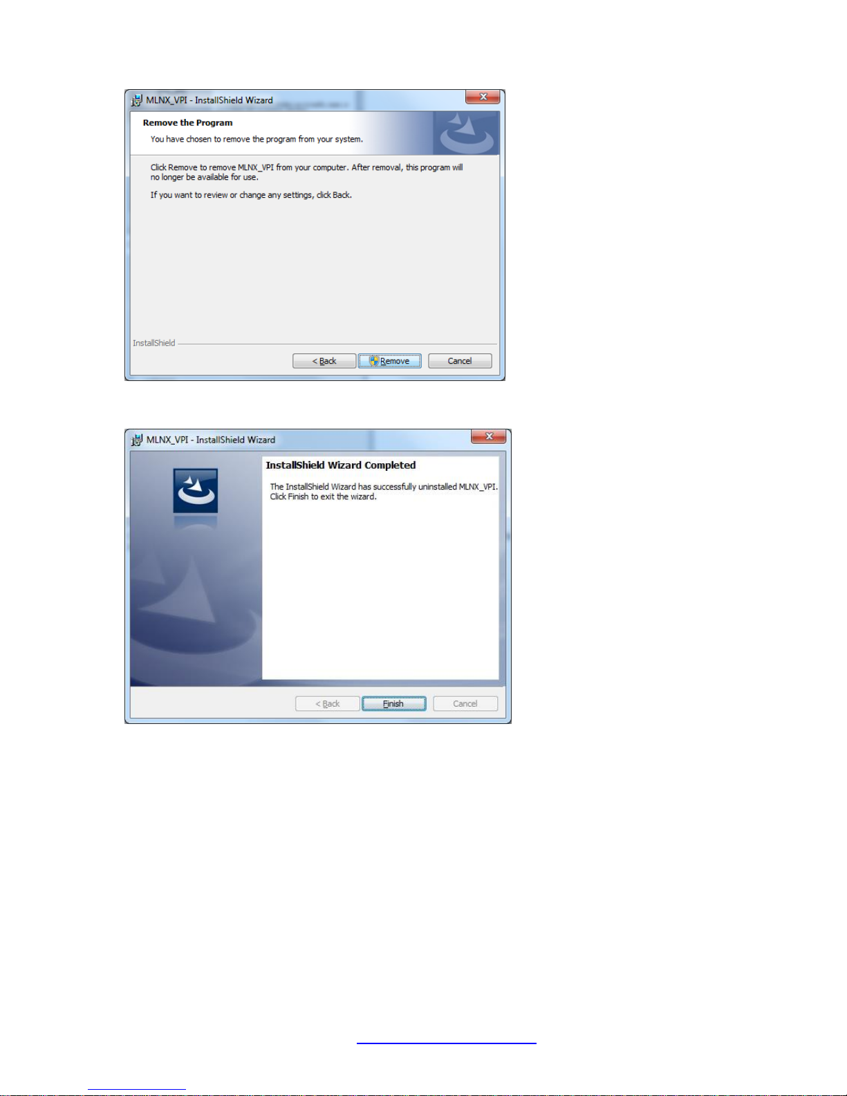
4. Click the Remove button to remove the MLNX_VPI driver from your computer. After removal, this
program will no longer be available for use.
5. Click the Finish button to exit the wizard.
33623 Rev. B https://www.transition.com/ Page 30 of 31
Page 31
Transition Networks N-TGE-SFP-01 User Guide
Uninstall the Driver
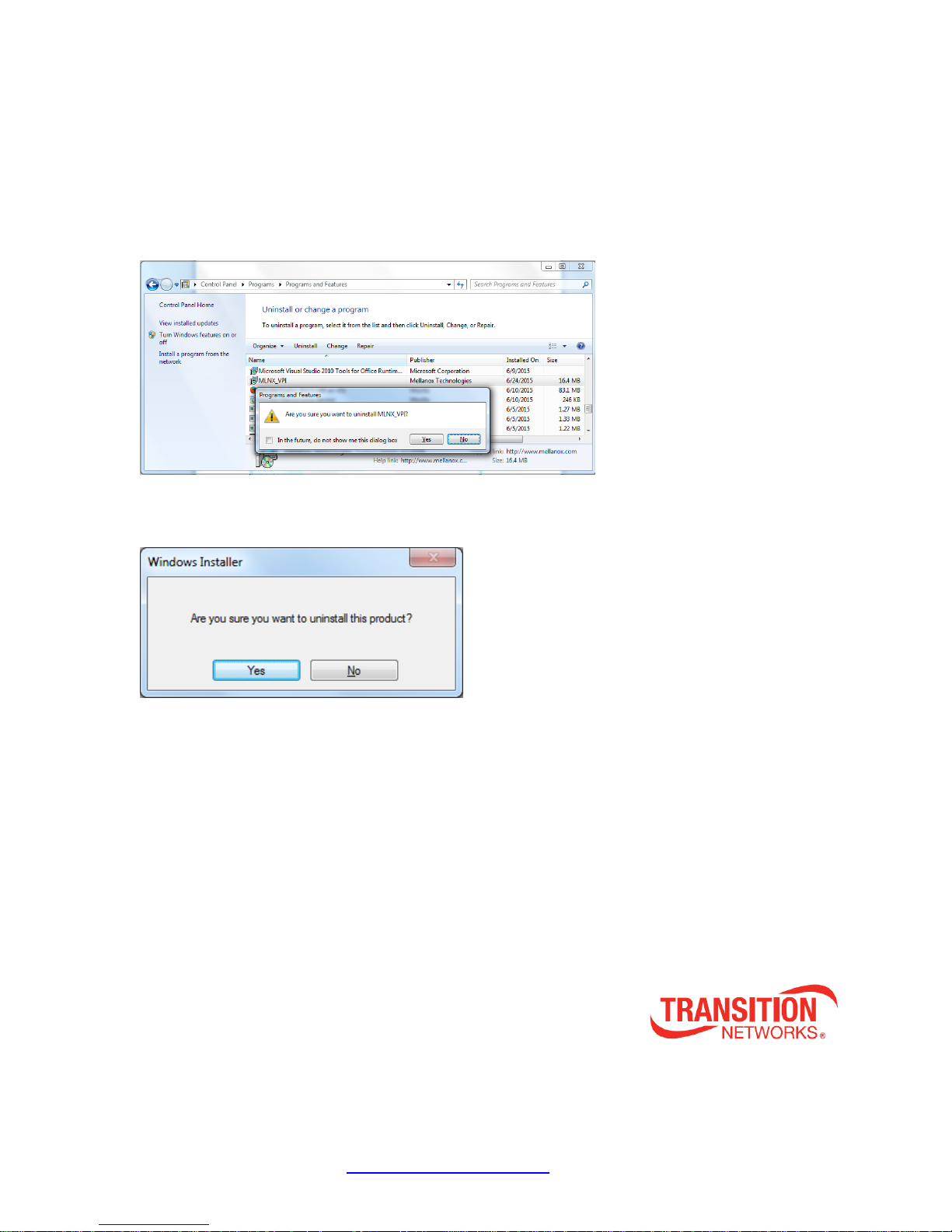
Uninstalling MLNX_VPI - Attended Uninstall
To uninstall MLNX_VPI on a single node, perform one of the following options:
1. Click Start-> Control Panel-> Programs and Features-> MLNX_VPI-> Remove.
Note: This requires elevated administrator.
2. Double click the .exe and follow the instructions of the install wizard.
3. Click Start-> All Programs-> Mellanox Technologies-> MLNX_VPI-> Uninstall MLNX_VPI.
4. At the Are you sure ...? prompt, click Yes.
Transition Networks ►10900 Red Circle Drive ►Minnetonka, MN 55343, U.S.A.
Telephone: 952-941-7600 ► Toll free: 800-526-9267 ► Fax: 952-941-2322
33623 Rev. B https://www.transition.com/ Page 31 of 31
 Loading...