

Transition Networks CSDTF1012-105, CSDTF1015-105, CSDTF1013-105, CSDTF1014-105, CSDTF1016-105 User Manual
...Page 1
Installation . . . . . . . . . . . . . . . . . . . . .3
Operation . . . . . . . . . . . . . . . . . . . . . .9
Cable Specifications . . . . . . . . . . . . .10
Technical Specifications . . . . . . . . . .12
Troubleshooting . . . . . . . . . . . . . . . .13
Compliance Information . . . . . . . . .16
* Typical maximum cable distance. Actual
distance is dependent upon the physical
characteristics of the network
Note: The CSDTF10xx-10x requires a CSU
between theDevice and the Public
Telephone Network.
CSDTF1027-105
RJ-45
1.5 km (5,000 feet) *
ST, 1300 nm multimode
5 km (3.1 miles)*
Part Number Port One - Copper Port Two - Duplex Fiber-Optic
CSDTF1011-105
RJ-45
1.5 km (5,000 feet) *
ST, 850 nm multimode
2 km (1.2 miles)*
CSDTF1012-105
RJ-45
1.5 km (5,000 feet) *
ST, 1310 nm single mode
8 km (4.8 miles)*
CSDTF1013-105
RJ-45
1.5 km (5,000 feet) *
SC, 850 nm multimode
2 km (1.2 miles)*
CSDTF1014-105
RJ-45
1.5 km (5,000 feet) *
SC, 1310 nm single mode
20 km (12.4 miles)*
CSDTF1015-105
RJ-45
1.5 km (5,000 feet) *
SC, 1310 nm single mode
40 km (24.8 miles)*
CSDTF1016-105
RJ-45
1.5 km (5,000 feet) *
SC, 1310 nm single mode
60 km (37.3 miles)*
CSDTF1017-105
RJ-45
1.5 km (5,000 feet) *
SC, 1550 nm single mode
80 km (49.7 miles)*
CSDTF1018-105
RJ-45
1.5 km (5,000 feet) *
MT-RJ, 1300 nm multimode
2 km (1.2 miles)*
CSDTF1022-105
RJ-45
1.5 km (5,000 feet) *
ST, 1310 nm single mode
15 km (9.3 miles)*
CSDTF1025-105
RJ-45
1.5 km (5,000 feet) *
MT-RJ, 1310 nm single mode
20 km (12.4 miles)*
User’s Guide
CSDTF10xx-10x
Slide-in-Module Devices
• T1 / E1 with Remote Management
• Copper to Fiber
Transition Networks CSDTF10xx-10x series Devices, designed
to be installed into the Transition Networks PointSystem™
chassis, encode and decode T1 or E1 twisted-pair copper
signals over fiber optic cable to extend the distance and
transmission reliability of high-speed T1 or E1 data traffic. The
device is framing independent (as ESF vs. D4) and supports all common line codes (e.g.,
AMI, B8ZS, HDB3).
The CSDTF10xx-10x is designed to be installed in pairs. For example, install one
CSDTF1011-105 as the “local” Device and another CSDTF1011-105 as the “remote”
Device.
Page 2
2
24-Hour Technical Support: 1-800-260-1312 -- International: 00-1-952-941-7600
CSDTF10xx-10x
(TX) = transmit (RX) = receive
* Typical maximum cable distance. Actual distance is dependent upon the physical
characteristics of the network.
** CSDTF1029-105 and -106 are intended to be installed in the same network where
one is the localDevice and the other is the remoteDevice.
*** CSDTF1029-107 and -108 are intended to be installed in the same network where
one is the localDevice and the other is the remoteDevice.
Part Number Port One - Copper Port Two - Single Fiber Optic
CSDTF1029-105 **
RJ-45
1.5 km (5,000 feet) *
SC, 1310 mn (TX)/1550 nm (RX)
single mode, 20 km (12.4 miles)*
CSDTF1029-106 **
RJ-45
1.5 km (5,000 feet) *
SC, 1550 mn (TX)/1310 nm (RX)
single mode, 20 km (12.4 miles)*
CSDTF1029-107 ***
RJ-45
1.5 km (5,000 feet) *
SC, 1310 mn (TX)/1550 nm (RX)
single mode, 40 km (24.8 miles)*
CSDTF1029-108 ***
RJ-45
1.5 km (5,000 feet) *
SC, 1550 mn (TX)/1310 nm (RX)
single mode, 40 km (24.8 miles)*
Note: The SSDTF10xx-10x model is the stand-alone version of the Device. For more
information, see the SSDTF10xx-10x user’s guide on-line at:
www.transition.com.
techsupport@transition.com -- Click the “Transition Now” link for a live Web chat.
3
Installation
CAUTION: Wear a grounding device and observe electrostatic discharge
precautions when setting the jumper and switches. Failure to observe this caution
could result in damage to, and subsequent failure of, the Device.
Set the Hardware/Software Jumper
• The hardware/software jumper is located on the circuit board and is labeled
“H” and “S”.
• Use a small needle-nose pliers or similar device to move the jumper to the
desired position.
Hardware The Device mode is determined by the
switch settings.
Software The Device mode is determined by the
most-recently saved, on-board
microprocessor settings.
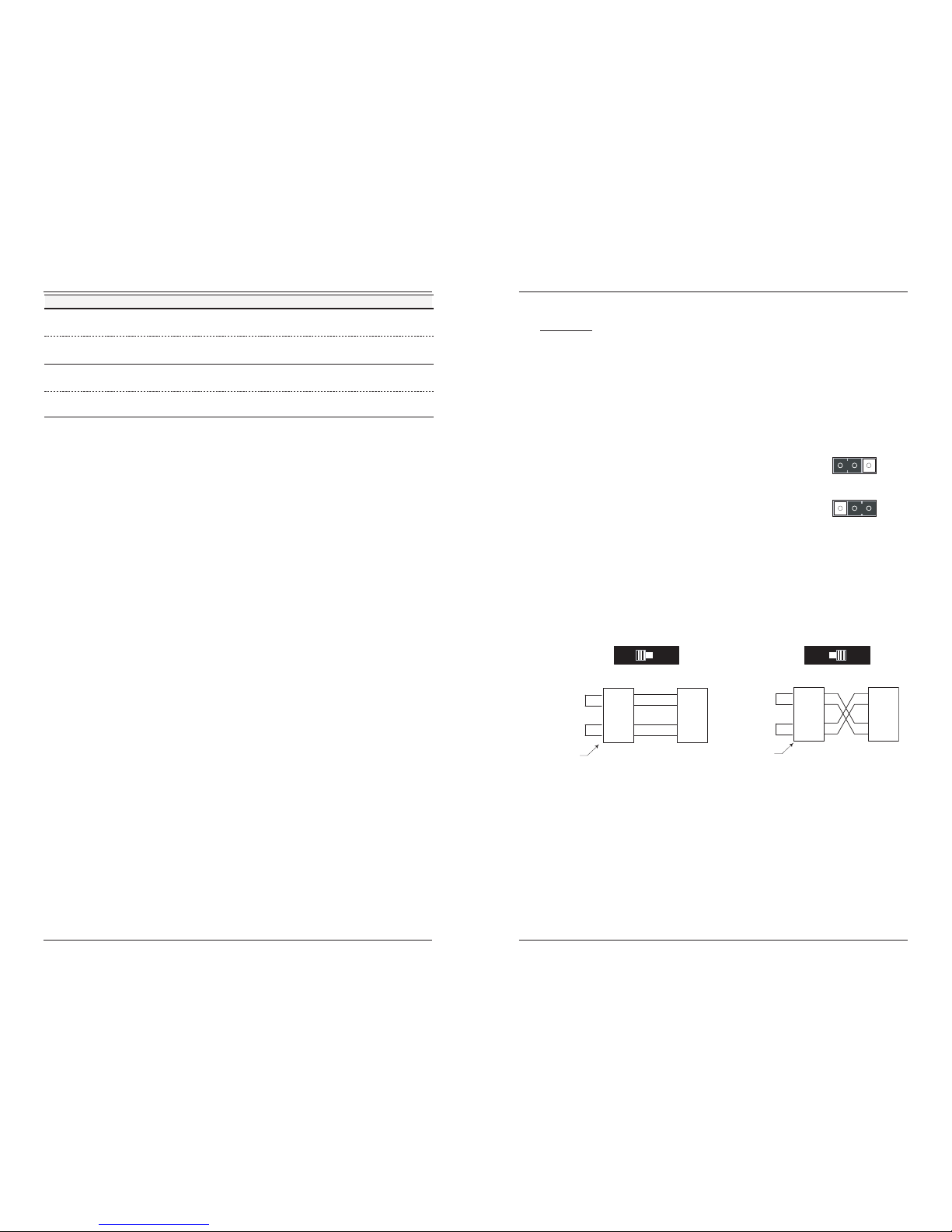
Set the MDI/MDI-X switch (hardware mode only)
The MDI/MDI-X switch is located on the side of the Device. This switch allows the
network administrator to use straight-through cable in installations where crossover
configuration cable is required. Use a small flat-blade screwdriver or a similar
device to set the recessed switch.
Set the switch to MDI if using
straight-through copper cable to
connect two unlike devices.
Set the switch to MDI-X if using
crossover copper cable to connect
two like devices.
Hardware Mode
Software Mode
H
HS
S
MDI
MDI-X
RTIP
RRING
TTIP
TRING
TTIP
TRING
RTIP
RRING
RTIP
RRING
TTIP
TRING
TTIP
TRING
RTIP
RRING
Straight-Through Cable
Crossover Cable
secived ekilnu rof rotcennoCsecived ekilnu rof rotcennoC
Twisted Pair #1
Twisted Pair #2
Twisted Pair #1
Twisted Pair #2
TN Device
TN Device
Page 3
4
24-Hour Technical Support: 1-800-260-1312 -- International: 00-1-952-941-7600
CSDTF10xx-10x
Installation -- Continued
Set the loop-back switch
Hardware mode:
The loop-back switch is located on the front panel of the Device and is used for
installation and network debugging procedures.
To set the switch, use a small flat-blade screwdriver or a
similar device (see the drawing to the right).
CL (Copper loop-back) Enable loop-back on the local copper interface.
-- (Center position) Normal operation.
FL (Fiber loop-back) Enable loop-back on the local fiber interface.
Software Mode:
If both Devices are under software control, the network administrator can initiate
the loop-back test function on the copper interface (local or remote) or on the fiber
interface (local or remote). These four loop-back test scenarios are described in
detail on page 14.
Set the configuration switches
The configuration switches are located on the side of the Device and are used to
configure the Device for various network conditions.
There are two sets (“left” is SW 2, and “right” is SW 1) each with four switches
labeled “1” through “4” as shown below.
Use a small, flat-blade screwdriver or a similar device to set the recessed switches.
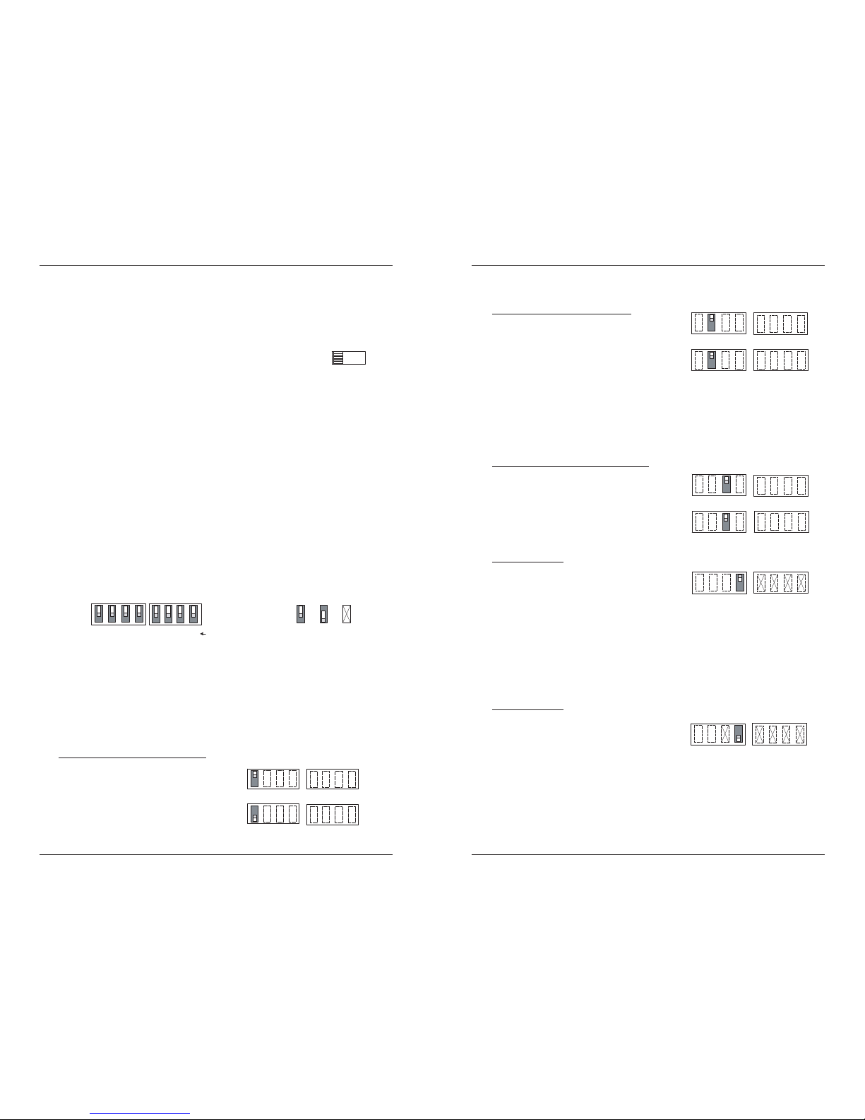
Transmit all ones (switches 1 & 2 of SW 2)
The transmit all ones function allows the insertion of an “all ones” pattern on the
copper and/or fiber interface when the signal detect is lost, creating an alarm
condition at the device connected to the interface.
Switch 1. Copper -- transmit all ones
UP - Disables the transmit all ones function
on the copper interface.
DOWN - Transmits an “all ones” pattern on
the copper interface when the signal detect
on the fiber interface is lost.
CL
FL
SW 2 SW 1
Rear Cable End
Config
Switc hes
1 2 3 4 1 2 3 4 Switch Numbers
Key:
UP
DOWN
Not Used
1234
Coax - Tran smit Al l Ones - Dis abled
Coax - Transmit All Ones - Enabled
techsupport@transition.com -- Click the “Transition Now” link for a live Web chat.
5
Installation -- Continued
Switch 2. Fiber -- transmit all ones
UP - Disables the transmit all ones function
on the fiber interface.
DOWN - Transmits an “all ones” pattern on
the fiber interface when the signal detect on
the copper interface is lost.
Select T1 configuration (switches 3 & 4, left set)
Use switches 3 and 4 to configure the Device for T1 configuration.
Switch 3. long haul/short haul
(T1 only)
UP - Short haul.
DOWN - Long haul.
Switch 4. T1 / E1
UP - T1 configuration.
Set switches 1, 2, 3, and 4 on the right set
for the required network cable settings
(see pages 6 and 7).
Select E1 configuration (switch 4, left set)
Use switch 4 to configure the Device for E1 configuration.
Switch 4. T1 / E1
DOWN- E1 configuration.
The default network cable setting is 3.0 V,
120 ohm.
Switch 3 on the left set and switches 1, 2, 3,
and 4 on the right set are disabled.
1234
Fiber - Transmit All Ones - Disabled
Fiber - Transmit All Ones - Enabled
1234
Short Haul (T1 only)
Long Haul (T1 only)
T1 Configuration
12344
123434
E1 — 3.0V 120 Ohm Cable
Page 4

6
24-Hour Technical Support: 1-800-260-1312 -- International: 00-1-952-941-7600
CSDTF10xx-10x
Installation -- Continued
T1/short-haul signal
Use switches 3 and 4 on the left switch set to select T1/short-haul signal (see the
drawing below).
Use switches 1, 2 and 3 on the right switch set to select the proper network cable
settings. The drawing below lists the seven options.
DSX-1 121.6 - 162.5 m
(399 - 533') 100 ohm cable
DSX-1 81 - 121.6 m
(266 - 399') 100 ohm cable
DSX-1 40.5 - 81 m
(133 - 266') 100 ohm cable
DSX-1 0 - 40.5 m
(0 - 133') ANSI T1.403
100 ohm cable
DSX-1 6.0 V
100 ohm cable
DSX-1 0 - 40.5 m
(0 - 133') 100 ohm cable
or
DSX-1 162.5 - 200 m
(533 - 655') 100 ohm cable
34 123
(T1/Short Haul)
4
(Switch 4 on the right switch set is not
used for configuring T1/short-haul
signals.)
techsupport@transition.com -- Click the “Transition Now” link for a live Web chat.
7
Installation -- Continued
Set the cable settings for T1 configuration
(right switch set)
T1/long-haul signal
Use switches 3 and 4 on the left switch set to select T1/long-haul signal (see the
drawing below).
Use switches 1 and 2 on the right switch set to select the proper network cable
settings. The drawing below lists the four options.
(Switches 3 and 4 on the right
switch set are not used for
configuring T1 / long-haul signals.)
-15.0 db 100 ohm cab
le
-7.5 db 100 ohm cabl
e
-22.5 db 100 ohm cab
le
34 12
0.0 db 100 ohm cable
(T1/Long-Haul)
34
Install the slide-in-module
CAUTION: Wear a grounding device and observe electrostatic discharge precautions
when installing the CSDTF10xx-10x slide-in-module Device. Failure to observe this
caution could result in damage to, and subsequent failure of, the Device.
1. Carefully slide the slide-in-module into the installation slot, aligning the
module with the installation guides.
2. Ensure that the module is firmly seated inside the chassis.
3. Push in and rotate the attached panel fastener screw clockwise to secure the
module to the chassis front.
Media Converter
Point System Chassis
Panel Fastener
Slot
Page 5

8
24-Hour Technical Support: 1-800-260-1312 -- International: 00-1-952-941-7600
CSDTF10xx-10x
Installation -- Continued
Install the copper cable
1. Locate or build twisted-pair copper cables that are compliant with the
specifications on page 11 with RJ-45 connectors at both ends.
2. Ensure that the MDI/MDI-X switch is set according to the network conditions
(see page 3).
3. Connect the RJ-45 connector at one end of cable to the RJ-45 port on the
Device.
4. Connect the RJ-45 connector at the other end of the cable to the RJ-45 port on
the other device (switch, workstation, etc.).
RJ-45 port
on the other device
(switch, work station, etc
.)
RJ-45 port
on the media
converter
Install the fiber cable
1. Locate or build fiber cables with male, two-stranded TX to RX connectors
installed at both ends.
2. Connect the fiber cables to the local CSDTF10xx-10x Device as described:
• Connect the male TX cable connector to the female TX port.
• Connect the male RX cable connector to the female RX port.
3. Connect the fiber cables to the remote CSDTF10xx-10x Device as described:
• Connect the male TX cable connector to the female RX port.
• Connect the male RX cable connector to the female TX port.
Connect fiber cable
to media converter
as shown.
Connect fiber cable
to other device
(media converter,
hub, etc.) as shown
RX
TX
RX
TX
techsupport@transition.com -- Click the “Transition Now” link for a live Web chat.
9
Operation
After installation, the Device should function without operator intervention. Use the
LEDs to monitor theDevice operation in the network.
SDC (Signal Detect/Copper) ON = the copper link is up.
SDF (Signal Detect/Fiber) ON = the fiber link is up.
PWR (Power) ON = the Device is connected to
external power.
Dry-contact relay
The RJ-45 copper port has a dry-contact relay that
opens if the power, signal detect/copper, or signal
detect/fiber are lost. The operational rating on pins
3 and 6 are 0-30VDC, 100mA (max).
Remote management function
A remote stand-alone Device (revision SSDTF10xx-105 or higher) can be managed
when connected to a local CSDTF10xx-105 Device. Please note that in a managed
network, both the local and remote Devices must be set to “software” mode (see
page 3).
SNMP
Use SNMP at an attached terminal or at a remote location to monitor the Device by
monitoring:
• Device power and hardware switch settings
• Copper link and fiber link status (local and/or remote)
• AIS detected on copper link and fiber link (local and/or remote)
Also, use SNMP to enter network commands that:
• Bootload the firmware (local only)
• Enable/disable loop-back on the copper link (local and/or remote)
• Enable/disable loop-back on the fiber link (local and/or remote)
• Enable/disable Transmit All Ones on the fiber link when the copper link
is down (local and/or remote)
• Enable/disable Transmit All Ones on the copper link when the fiber link
is down (local and/or remote)
• Power-down the Device
See the on-line documentation that comes with Transition Networks FocalPoint™
software for commands and usage at www.transition.com.
Relay
3
6
RJ-45 Connect
o
CSDTF
Fiber
SDFSDC PWR
TX
RX
CL
FL
UTP/STP
Page 6

10
24-Hour Technical Support: 1-800-260-1312 -- International: 00-1-952-941-7600
CSDTF10xx-10x
Cable Specifications
Fiber Cable
single mode fiber (recommended): 9 µm
Multimode fiber (recommended): 62.5/125 µm
Multimode fiber (optional): 100/140, 85/140, 50/125 µm
CSDTF1011-105 850 nm multimode
Fiber Optic Transmitter Power: min: -19.0 dBm max: -14.0 dBm
Fiber Optic Receiver Sensitivity: min: -32.5 dBm max: -14.0 dBm
Link Budget: 13.5 dB
CSDTF1012-105 1310 nm single mode
Fiber-optic Transmitter Power: min: -27.0 dBm max: -10.0 dBm
Fiber-optic Receiver Sensitivity: min: -34.0 dBm max: -14.0 dBm
Link Budget: 7.0 dB
CSDTF1013-105 850 nm multimode
Fiber Optic Transmitter Power: min: -19.0 dBm max: -14.0 dBm
Fiber Optic Receiver Sensitivity: min: -32.5 dBm max: -14.0 dBm
Link Budget: 13.5 dB
CSDTF1014-105 1310 nm single mode
Fiber-optic Transmitter Power: min: -19.0 dBm max: -14.0 dBm
Fiber-optic Receiver Sensitivity: min: -34.0 dBm max: -3.0 dBm
Link Budget: 15.0 dB
CSDTF1015-105 1310 nm single mode
Fiber Optic Transmitter Power: min: -8.0 dBm max: -2.0 dBm
Fiber Optic Receiver Sensitivity: min: -38.0 dBm max: -8.0 dBm
Link Budget: 30.0 dB
CSDTF1016-105 1310 nm single mode
Fiber-optic Transmitter Power: min: -5.0 dBm max: 0.0 dBm
Fiber-optic Receiver Sensitivity: min: -38.0 dBm max: -8.0 dBm
Link Budget: 33.0 dB
CSDTF1017-105 1550 nm single mode
Fiber-optic Transmitter Power: min: -5.0 dBm max: 0.0 dBm
Fiber-optic Receiver Sensitivity: min: -34.0 dBm max: -7.0 dBm
Link Budget: 29.0 dB
CSDTF1018-105 1300 nm multimode
Fiber-optic Transmitter Power: min: -19.0 dBm max: -14.0 dBm
Fiber-optic Receiver Sensitivity: min: -33.5 dBm max: -14.0 dBm
Link Budget: 14.5 dB
CSDTF1022-105 1310 nm single mode
Fiber Optic Transmitter Power: min: -15.0 dBm max: -5.0 dBm
Fiber Optic Receiver Sensitivity: min: -25.0 dBm max: -14.0 dBm
Link Budget: 10.0 dB
CSDTF1025-105 1310 nm single mode
Fiber-optic Transmitter Power: min: -11.0 dBm max: -3.0 dBm
Fiber-optic Receiver Sensitivity: min: -20.0 dBm max: -3.0 dBm
Link Budget: 9.0 dB
techsupport@transition.com -- Click the “Transition Now” link for a live Web chat.
11
Cable Specifications -- Continued
Fiber cable
CSDTF1027-105 1300 nm multimode
Fiber Optic Transmitter Power: min: -19.0 dBm max: -15.0 dBm
Fiber Optic Receiver Sensitivity: min: -32.5 dBm max: -14.0 dBm
Link Budget: 13.5 dB
CSDTF1029-105 1310 nm (TX) / 1550 nm (RX) simplex
Fiber-optic Transmitter Power: min: -13.0 dBm max: -6.0 dBm
Fiber-optic Receiver Sensitivity: min: -32.0 dBm max: -3.0 dBm
Link Budget: 19.0 dB
CSDTF1029-106 1550 nm (TX) / 1310 nm (RX) simplex
Fiber-optic Transmitter Power: min: -13.0 dBm max: -6.0 dBm
Fiber-optic Receiver Sensitivity: min: -32.0 dBm max: -3.0 dBm
Link Budget: 19.0 dB
CSDTF1029-107 1310 nm (TX) / 1550 nm (RX) simplex
CSDTF1029-108 1550 nm (TX) / 1310 nm (RX) simplex
Fiber-optic Transmitter Power: min: -8.0 dBm max: -3.0 dBm
Fiber-optic Receiver Sensitivity: min: -33.0 dBm max: -3.0 dBm
Link Budget: 25.0 dB
The fiber optic transmitters on this device meet Class I Laser safety requirements
per IEC-825/CDRH standards and comply with 21 CFR1040.10 and
21CFR1040.11.
Copper cable
Connector: RJ-45 / RJ-48C
Elec. network connection: Single 4-wire (Tip/Ring - Tip1/Ring1)
Mechanical arrangement: 8-position miniature modular jack
Usage: 1.544 Mb/s or 2.0478 Mb/s access lines
Interface codes: 04DU9 (any applicable)
Cable type:
Long Haul T1: 0db, -7.5dp, -15db, -22db
E1 (120 ohm): E1 3.0V, 120
J1 (110 ohm): 0-655’, 110
DSX-1 (100 ohm): 0-133’, 133-266’, 266-399’,
399-533’, 533-655’
1
2
3
4
5
6
7
8
1
2
3
4
5
6
7
8
R
T
Dry Contact B
Transmit
R1
T1
Dry Contact
A
Receive
(ring) R
(tip) T
(ring) R1
(tip) T1
(not used)
Page 7

12
24-Hour Technical Support: 1-800-260-1312 -- International: 00-1-952-941-7600
CSDTF10xx-10x
Technical Specifications
For use with Transition Networks Model CSDTF10xx-10x or equivalent
Standards: Emissions: CISPR A; Telecordia TR-NWT-001089
(designed to meet; NOT tested); FCC Part 68; T1/E1
Physical layer: ITU-T, ANSI, AT&T, and ETSI; European
Technical Standard: TBR 12; British Technical
Publication: PD 7024 : 1994 (NTR 4)
Dimensions: 3.4" x 5" x 0.87" (86 mm x 182 mm x 22 mm)
Weight: 3 oz. (91 g) approximately
Power Consumption: 3.7 Watts
MTBF: 342,000 (MIL217F2 V5.0) (MIL-HDBD-217F)
933,000 (Bellcore7 V5.0)
Environment: 0°C to 60°C (32°F to 140° F )
Storage Temp: -15°C to 65°C (5°F to 149°F)
Humidity: 10% to 90%, non condensing
Altitude: 0 to 10,000 feet
Warranty: Lifetime
*Manufacturer’s rated ambient temperature: Tmra range for this slide-in-module
depends on the physical characteristics and the installation configuration of the
Transition Networks PointSystem™ chassis in which this slide-in-module will be
installed.
The information in this user’s guide is subject to change. For the most up-to-date
information on the CSDTF10xx-10x Device, view the user’s guide on-line at:
www.transition.com.
Product is certified by the manufacturer to comply with DHHS Rule 21/CFR,
Subchapter J applicable at the date of manufacture.
CAUTION:
Visible and invisible laser radiation when open. Do not stare into the
beam or view directly with optical instruments.
CAUTION:
Use of controls, adjustments or the performance of procedures other than
those specified herein may result in hazardous radiation exposure.
techsupport@transition.com -- Click the “Transition Now” link for a live Web chat.
13
Troubleshooting
If the Device fails, isolate and correct the failure by determining the answers to the
following questions and then taking the indicated action:
1. Is the PWR (Power) LED illuminated?
NO
• Is the Device slide-in-module installed properly in the chassis?
• Is the power cord properly installed in the chassis and at the external
power source?
• Does the external power source provide power?
• Contact Tech Support: 1-800-260-1312, Int’l: 00-1-952-941-7600.
YES
• Proceed to step 2.
2. Is the SDC (Signal Detect / Copper) LED illuminated?
NO
• Check the twisted-pair copper cable for the proper connection.
• Check the MDI/MDI-X switch for the correct twisted-pair copper cable
configuration (see page 3).
• Contact Tech Support: 1-800-260-1312, Int’l: 00-1-952-941-7600.
YES
• Proceed to step 3.
3. Is the SDF (Signal Detect / Fiber) LED illuminated?
NO
• Check the fiber cables for proper connection.
• Verify that the TX and RX cables on the local Device are connected to the
RX and TX ports, respectively, on the remote Device.
• Contact Tech Support: 1-800-260-1312, Int’l: 00-1-952-941-7600.
YES
• Proceed to step 4.
Page 8

4. Is data transfer failing?
YES
• Verify the local copper connection by starting a local copper loop-back
(hardware mode: set the loop-back switch on the local Device to “CL”,
software mode: enter the local copper loop-back command) and then use
a bit error test unit to run a bit error test.
• Verify the local fiber connection by starting a remote fiber loop-back
(hardware mode: set the loop-back switch on the remote Device to “FL”,
software mode: enter the remote fiber loop-back command) and then use a
bit error test unit to run a bit error test.
• Verify the remote copper connection by starting a remote copper loopback (hardware mode: set the loop-back switch on the remote Device to
“CL”, software mode: enter the remote copper loop-back command) and
then use a bit error test unit to run a bit error test.
• Verify the remote fiber connection by starting a local copper loop-back
(hardware mode: set the loop-back switch on the local Device to “FL”,
software mode: enter the local fiber loop-back command) and then use a
bit error test unit to run a bit error test.
• Contact Tech Support: 1-800-260-1312, Int’l: 00-1-952-941-7600.
NO
• Contact Tech Support: 1-800-260-1312, Int’l: 00-1-952-941-7600.
reppoCrebiFreppoC
Local
Device
Remote
Device
Bit Error
Test Unit
Remote
Device
reppoCrebiFreppoC
Bit Error
Test Unit
Local
Device
Remote
Device
Local
Device
reppoCrebiFreppoC
Bit Error
Test Unit
Local
Device
Local
Device
Remote
Device
reppoCrebiFreppoC
Bit Error
Test Unit
Local
Device
Remote
Device
Local
Device
14
24-Hour Technical Support: 1-800-260-1312 -- International: 00-1-952-941-7600
CSDTF10xx-10x
techsupport@transition.com -- Click the “Transition Now” link for a live Web chat.
15
Contact Us
Technical support
Technical support is available 24 hours a day.
U.S.A. and Canada: 1-800-260-1312
International: 00-1-952-941-7600
Transition now
Chat live via the Web with Transition Networks Technical Support.
Log onto www.transition.com and click the Transition Now link.
Web-Based seminars
Transition Networks provides seminars via live web-based training.
Log onto www.transition.com and click the Learning Center link.
E-Mail
Ask a question anytime by sending an e-mail to our technical support staff.
techsupport@transition.com
Address
Transition Networks
10900 Red Circle Drive
Minnetonka, MN 55343, U.S.A.
Telephone: 952-941-7600
Toll free: 800-526-9267
Fax: 952-941-2322
Declaration of Conformity
Name of Mfg: Transition Networks
10900 Red Circle Drive, Minnetonka MN 55343 U.S.A.
Model: CSDTF10xx-10x Series Devices
Part Number: CSDTF1011-105, CSDTF1012-105, CSDTF1013-105,
CSDTF1014-105, CSDTF1015-105, CSDTF1016-105,
CSDTF1017-105, CSDTF1018-105, CSDTF1022-105,
CSDTF1025-105, CSDTF1027-105, CSDTF1029-105,
CSDTF1029-106, CSDTF1029-107, CSDTF1029-108
Regulation: EMC Directive 89/336/EEC
Purpose: To declare that the CSDTF10xx-10x to which this declaration refers is in
conformity with the following standards.
CISPR 22:1993; EN 55022:1994+A1:1995+A2:1997 Class A; EN 55024:1998; FCC Part 15
Subpart B; EN 61000-3-2:1995+A14:2000; 61000-3-3:1995; CFR 21 subpart J
I, the undersigned, hereby declare that the equipment specified above conforms to the above
Directive(s) and Standard(s).
September, 2008
Stephen Anderson, Vice-President of Engineering Date
Page 9

Compliance Information
CISPR22/EN55022 Class A + EN55024
CE Mark
FCC regulations
This equipment has been tested and found to comply with the limits for a Class A digital device,
pursuant to part 15 of the FCC rules. These limits are designed to provide reasonable protection
against harmful interference when the equipment is operated in a commercial environment. This
equipment generates, uses, and can radiate radio frequency energy and, if not installed and used in
accordance with the instruction manual, may cause harmful interference to radio communications.
Operation of this equipment in a residential area is likely to cause harmful interference, in which
case the user will be required to correct the interference at the user's own expense.
Canadian regulations
This digital apparatus does not exceed the Class A limits for radio noise for digital apparatus set out
on the radio interference regulations of the Canadian Department of Communications.
Le présent appareil numérique n'émet pas de bruits radioélectriques dépassant les limites applicables
aux appareils numériques de la Class A prescrites dans le Règlement sur le brouillage
radioélectrique édicté par le ministère des Communications du Canada.
European regulations
Warning
This is a Class A product. In a domestic environment this product may cause radio interference in
which case the user may be required to take adequate measures.
Achtung !
Dieses ist ein Gerät der Funkstörgrenzwertklasse A. In Wohnbereichen können bei Betrieb dieses
Gerätes Rundfunkstörungen auftreten. In diesem Fäll ist der Benutzer für Gegenmaßnahmen
verantwortlich.
Attention !
Ceci est un produit de Classe A. Dans un environment domestique, ce produit risque de créer des
interférences radioélectriques, il appartiendra alors à l'utilsateur de prende les measures spécifiques
appropriées.
Trademark notice
All trademarks and registered trademarks are the property of their respective owners.
Copyright restrictions
© 2002-2005 Transition Networks.
All rights reserved. No part of this work may be reproduced or used in any form or by any means graphic, electronic, or mechanical - without written permission from Transition Networks.
Printed in the U.S.A. 33245.H
16
CSDTF10xx-10x
CAUTION: RJ connectors are NOT INTENDED FOR CONNECTION TO THE
PUBLIC TELEPHONE NETWORK. Failure to observe this caution could result in
damage to the public telephone network.
Der Anschluss dieses Gerätes an ein öffentlickes Telekommunikationsnetz in den EGMitgliedstaaten verstösst gegen die jeweligen einzelstaatlichen Gesetze zur Anwendung der
Richtlinie 91/263/EWG zur Angleichung der Rechtsvorschriften der Mitgliedstaaten über
Telekommunikationsendeinrichtungen einschliesslich der gegenseitigen Anerkennung ihrer
Konformität.
In accordance with European Union Directive 2002/96/EC of the European
Parliament and of the Council of 27 January 2003, Transition Networks will accept
post usage returns of this product for proper disposal. The contact information for this
activity can be found in the 'Contact Us' portion of this document.
 Loading...