

Transition Networks CFMFF4040-100, TN-SFP-LX1, TN-SFP-LX12, TN-SFP-LX3, TN-SFP-LX5 User Manual
...Page 1
User’s Guide
CFMFF4040-100
Optical Line Converter for
Small Form Factor Pluggable (SFP)
Transceiver Modules
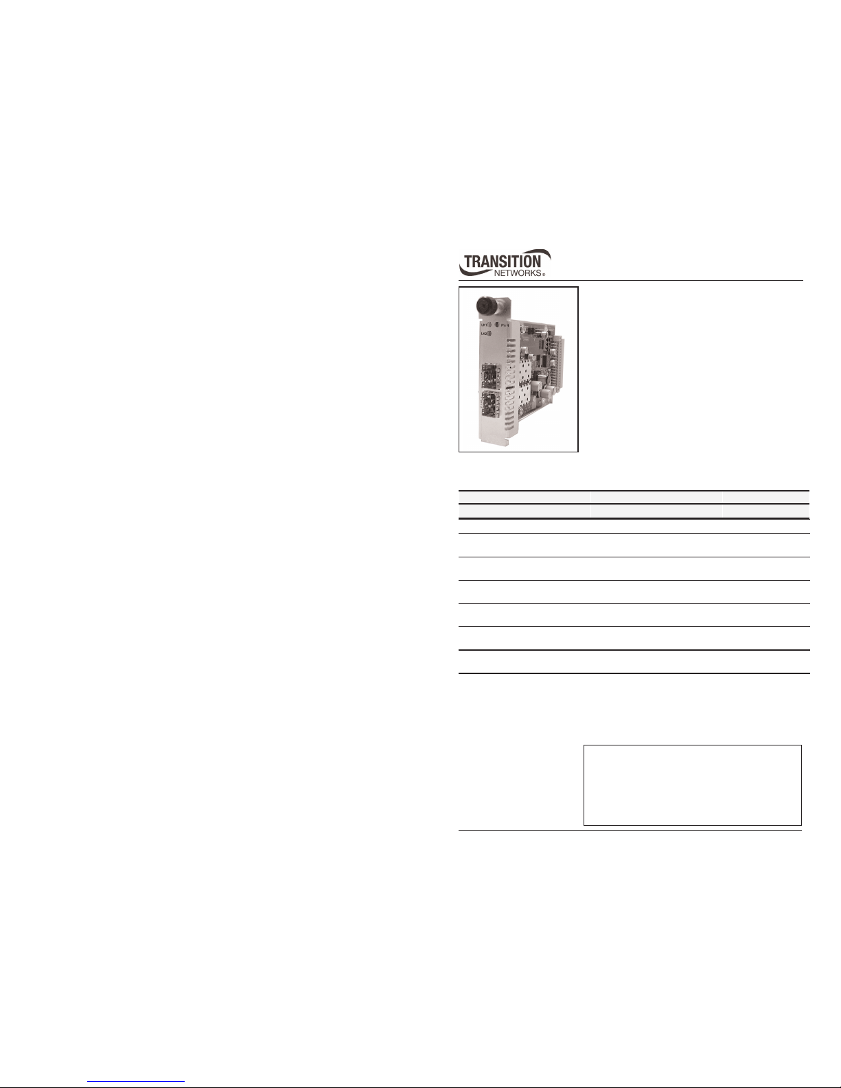
The Transition Networks CFMFF4040-100 optical
line converter is designed to accommodate two (2)
small form factor pluggable (SFP) transceiver
modules; and install into the Transition Networks
PointSystem™ chassis.
Port 1 Port 2
CFMFF4040-100 empty empty
Installation . . . . . . . . . . . . . . . . . . . . . . . . . . . . .3
Operation . . . . . . . . . . . . . . . . . . . . . . . . . . . . .5
Diagnostic Monitor Interface (DMI) . . . . . . . . . .7
Technical Specifications . . . . . . . . . . . . . . . . . .8
Troubleshooting . . . . . . . . . . . . . . . . . . . . . . . . .9
Contact Us . . . . . . . . . . . . . . . . . . . . . . . . . . . .10
Compliance Information . . . . . . . . . . . . . . . . .11
Part Number Description
TN-SFP-SX LC, 1000Base-SX, 850 nm multimode, 220-500 mm (720-1640 ft)*
TN-SFP-LX1 LC, 1000Base-LX, 1310 nm single mode, 10 km (6.2 miles)*
with DMI
TN-SFP-LX3 LC, 1000Base-LX, 1310 nm single mode, 30 km (18.8 miles)*
with DMI
TN-SFP-LX5 LC, 1000Base-LX, 1550 nm single mode, 50 km (31.2 miles)*
with DMI
TN-SFP-LX8 LC, 1000Base-LX, 1550 nm single mode, 80 km (50.0 miles)*
with DMI
TN-SFP-LX12 LC, 1000Base-LX, 1550 nm single mode, 120 km (74.56 miles)*
with DMI
The following SFP transceiver modules are compatible with the CFMFF4040-100
converter and are available from Transition Networks (sold separately).
Page 2

CFMFF4040-100
2
Tech Support: 1-800-260-1312 -- International: 00-1-952-941-7600 -- (24 hours)
With any two Transition Networks SFP transceiver modules installed, the
CFMFF4040-100 converter can perform the following mode conversions:
• multimode to multimode
• multimode to single mode
• single mode to single mode
Also the following wavelength line conversions:
• 850 nm to 850 nm • 850 nm to 1310 nm • 850 nm to 1550 nm
• 1310 nm to 850 nm • 1310 nm to 1310 nm • 1310 nm to 1550 nm
• 1550 nm to 850 nm • 1550 nm to 1310 nm • 1550 nm to 1550 nm
• CWDM (coarse wavelength division multiplexing)
• DWDM (dense wavelength division multiplexing)
Optical line converter -- continued
The following SFP transceiver modules are compatible with the CFMFF4040-100
converter and are available from Transition Networks (sold separately).
Part number Duplex Fiber Optic
TN-SFP-OC3M LC, 100Base-FX/OC-3 SFP 1300 nm multimode 2km (1.2 miles)*
with DMI
TN-SFP-OC3S LC, 100Base-FX/OC-3 SFP 1310 nm single mode 20km (12.4miles)*
with DMI
TN-SFP-OC12M LC, OC-12/STM-4 SFP 1300 nm multimode 1 km (0.6 miles)*
with DMI
TN-SFP-OC12S LC, OC-12/STM-4 SFP 1310 nm single mode 20 km (12.4 miles)*
with DMI
TN-SFP-FC2XM LC, 2x/1x/OC-48/STM-16/1000Base-SX, 850 nm multimode, DMI,
150 m (492 ft)* on 62.5/125 µm fiber,
300 m (984ft)* on 50/125 µm fiber
TN-SFP-FC2XS2 LC, 2x/1x/OC-48/STM-16/1000Base-LX, 1310 nm single mode, 2
km (1.2 miles)* with DMI
TN-SFP-FC2XS15 LC, 2x/1x/OC-48/STM-16/1000Base-LX, 1310 nm single mode, 15
km (9.3 miles)* with DMI
TN-SFP-FC2XS40 LC, 2x/1x/OC-48/STM-16/1000Base-LX, 1310 nm single mode, 40
km (24.9 miles)* with DMI
*Unless otherwise indicated, the distances listed are the typical maximum cable
distance. The actual maximum cable distances are dependent upon the physical
characteristics of the network installation.
techsupport@transition.com -- Click the “Transition Now” link for a live Web chat.
3
Installation
Set the HW/SW Jumper
• The jumper is located on the circuit board, labeled
“J1”.
• Use needle-nose pliers to set the jumper.
Hardware: The media converter settings can be monitored
using SNMP, but cannot be managed.
Software: The media converter settings are monitored and
managed using SNMP.
Install the Slide-In-Module
IMPORTANT: Slots in the PointSystem™ chassis that do not have a module
installed MUST have a protective plate covering the empty slot for Class A
and/or Class B compliance.
Note: The slide-in-modules may be installed in any slot and in any order.
To install the CFMFF4040-100 optical line converter:
1. Locate an empty installation slot on the PointSystem™ chassis.
2. Carefully slide the converter into the slot, aligning the it with the
installation guides.
3. Ensure that the module is firmly seated inside the chassis.
4. Push in and rotate the the attached panel fastener screw clockwise to
secure the module to the chassis front.
CFMFF100
CFMFF100
CETCF100
CFETF100
CFMFF100
SPD
PWR
FRX
CRX
FLNK
CLNK
10/100TX
RX
TX
10/100SX
100BASE-TX
RX
TX
100BASE-FX
Link Alert
E
D
0
50½
LA
PWR
RXF
RXC
LNK
COL
LKS
PWR
LKM
10BASE-2
10BASE-FL
LKS
PWR
LKM
LKS
PWR
LKM
Multimode
Singlemode
TX
RX
TX
RX
Multimode
Singlemode
TX
RX
TX
RX
Multimode
Singlemode
TX
RX
TX
RX
I
0
TERM
INIT
RX
TX
LNK
PWR
CPSMM120
SERIAL
10BASE-T
R
E
S
E
T
I
0
Panel Fastener Screw
PWR
LK1 PWR
LK2
Port 2Port 1
Software Mode
Hardware Mode
H
S
H
S
J1
J1
Page 3
CFMFF4040-100
4
Tech Support: 1-800-260-1312 -- International: 00-1-952-941-7600 -- (24 hours)
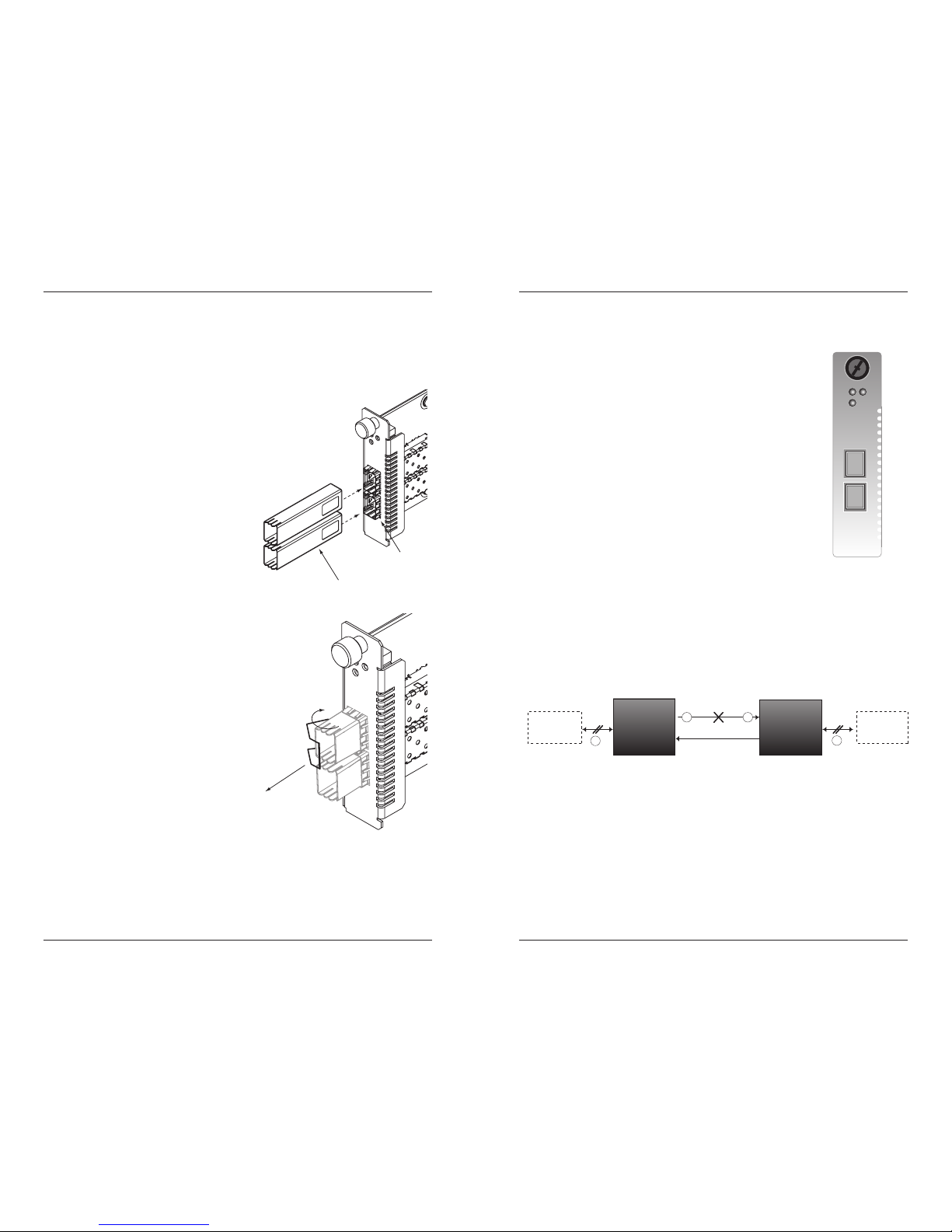
Install SFP Transceiver Modules
To install SFP transceiver modules into the
CFMFF4040-100 converter:
1. Position the SFP transceiver module at
the installation slot so that the label
faces to the right.
2. Carefully slide the module into one of
the installation slots, aligning the
module with the internal installation
guides.
3. Ensure that the module is firmly seated
against the internal mating connector.
4. Repeat steps 1 thru 3 to install a
module into the second slot.
SFP transceiver
modules
installation
slots
Remove SFP Transceiver Modules
To remove a SFP transceiver module from
the CFMFF4040-100 converter:
1. Swing the handle on the SFP transceiver
to the “out” position, shown to the
right.
2. Carefully pull the module outward until
it separates from the converter.
1.
2.
Installation -- continued
Power the Media Converter
The CFMFF4040-100 optical line converter is powered through the
Transition Networks PointSystem™ chassis.
techsupport@transition.com -- Click the “Transition Now” link for a live Web chat.
5
Operation
Status LEDs
The CFMFF4040-100 optical line converter is designed to
operate without user intervention. Use the status LEDs to
monitor the operation of the converter in the network.
PWR (Power) On = Connection to external power.
LK1 (Fiber Link 1) On = Fiber port 1 is receiving a signal.
LK2 (Fiber Link 2) On = Fiber port 2 is receiving a signal.
LK1 PWR
LK2
Port 2Port 1
CFMFF
Link Pass-Through
The Link Pass-Through feature allows the media converter to monitor both
fiber RX (receive) ports for loss of signal. In the event of an RX signal loss (1),
the media converter will automatically disable the TX (transmit) signal (2),
thus, “passing through” the link loss (3). The far-end device is automatically
notified of the link loss (4), which prevents the loss of valuable data
unknowingly transmitted over an invalid link.
4
1
Media
Converter A
Media
Converter B
Near-End
Device
Far-End
Device
original fault
on the fiber link
media converter B
disables the fiber link
media converter A
disables the fiber TX link
3
2
media converter B
loses the fiber RX link
Note: Link losses will be automatically repaired by the converters.
Page 4

CFMFF4040-100
6
Tech Support: 1-800-260-1312 -- International: 00-1-952-941-7600 -- (24 hours)
Operation -- continued
SNMP
Use SNMP at an attached terminal or at a remote location to supervise the
media converter by monitoring:
• Media converter power*
• Presence of SFP modules
• Fiber link status
• SFP vendor and model*
• Media converter temperature*
• TX/RX power*
Also, use SNMP to enter network commands that:
• Turn ON/OFF the media converter
• Turn ON/OFF the SFP ports
See the on-line documentation that comes with Transition Networks
FocalPoint™ software for applicable commands and usage at
www.transition.com.
* Some third-party manufacturers of SFP modules might not provide these
features in their product. If this is the case, the FocalPoint™ software will not
display these features.
techsupport@transition.com -- Click the “Transition Now” link for a live Web chat.
7
Diagnostic Monitoring Interface (DMI)
The following DMI port screen and explanation table contains brief definitions of
the DMI support offered on Transition Networks SFP optical interfaces. For further
information, please see the help option on the CPSMM-xxx SNMP agent or Focal
Point, Transition Networks' GUI.
Variable Name Description
DMI Rx Power Measured Receive optical power in microwatts and in
decibels relative to 1mW.
DMI Rx Power Alarm Alarm status of measured Receive optical power.
DMI Temp Internally measured temperature of transceiver in degrees C
and degrees F.
DMI Temp Alarm Alarm status for internally measured temperature of
transceiver.
DMI Bias Current Measured transmit bias current in microamperes.
DMI Bias Alarm Alarm status for measured transmit bias current for the
interface.
DMI Tx Power Measured transmit power, in microwatts and in decibels
relative to 1mW..
DMI Tx Power Alarm Alarm status of measured transmit power.
Rx Power Intrusion
Threshold
Instructs the converter to stop passing traffic when the
receive power drops below the new threshold. This feature
is sometimes referred to as 'Intrusion Detection,' since
tapping into a fiber to intercept traffic leads to a reduction
in receive power. This value can be entered in microwatts
or in decibels relative to 1mW.
Note: This feature is not available on all devices.
Page 5

CFMFF4040-100
8
Tech Support: 1-800-260-1312 -- International: 00-1-952-941-7600 -- (24 hours)
Technical Specifications
For use with Transition Networks model CFMFF4040-100 or equivalent.
Standards MSA (Multi-Source Agreement) compliant SFP
(Small Form Factor Pluggables)
Dimensions 3.4 x 5.0 x 0.87 (86 x 182 x 22 mm)
Weight 3 oz. (91 g) approximately
Power consumption 2.0 Watts with two (2) Transition Networks SFPs
installed (Power consumption depends on the type of
SFPs installed.)
Environment
Tmra*: -10° to 60°C (14° to 185°F)
Storage Temp: -40° to 85°C (14° to 185°F)
Humidity: 5 to 95%, non-condensing
Altitude: 0 to 10,000 feet
Warranty Lifetime
*Manufacturer’s rated ambient temperature: “Tmra” range for this slide-inmodule depends on the physical characteristics and the installation configuration
of the Transition Networks PointSystem™ chassis in which this slide-in-module
will be installed.
The information in this user’s guide is subject to change. For the most up-to-date
information on the CFMFF4040-100 optical line converter, view the user’s guide
on-line at: www.transition.com.
The stand-alone version of this media converter is SFMFF4040-100. For more
information, see the SFMFF4040-100 user’s guide on-line at:
www.transition.com.
techsupport@transition.com -- Click the “Transition Now” link for a live Web chat.
9
Troubleshooting
If the CFMFF4040-100 converter fails, isolate and correct the failure by
determining the answers to the following questions and taking the indicated
action:
1. Is the PWR (power) LED illuminated?
NO
• Ensure the converter is inserted properly into the chassis.
• Ensure the power cord is properly installed in the chassis and in the
grounded outlet.
• Ensure the grounded outlet provides power.
• Contact Technical Support: US/Canada: 1-800-260-1312, International:
00-1-952-941-7600.
YES
• Proceed to step 2.
2. Are both LK1 & LK2 LEDs (fiber link for ports 1 & 2) illuminated?
NO
• Ensure both SFP transceiver modules are properly inserted in the
converter.
• Check the fiber cables for proper connection.
• Verify that the TX and RX cables on the media converter are connected to
the RX and TX ports, respectively, on the other device.
• Contact Technical Support: US/Canada: 1-800-260-1312, International:
00-1-952-941-7600.
YES
• Proceed to step 3.
3. Is the LK1 LED (fiber link 1) flashing?
NO
• If there is no network activity on port 1, proceed to step 4.
• If there is network activity on port 1, disconnect and reconnect the fiber
cables to restart the initialization process.
• Contact Technical Support: US/Canada: 1-800-260-1312, International:
00-1-952-941-7600.
YES
• Proceed to step 4.
4 Is the LK2 LED (fiber link 2) flashing?
NO
• If there is no network activity on port 2, contact technical support.
• If there is network activity on port 2, disconnect and reconnect the fiber
cables to restart the initialization process.
• Contact Technical Support: US/Canada: 1-800-260-1312, International:
00-1-952-941-7600.
Page 6

CFMFF4040-100
10
Tech Support: 1-800-260-1312 -- International: 00-1-952-941-7600 -- (24 hours)
Contact Us
Technical support
Technical support is available 24 hours a day.
US and Canada: 1-800-260-1312
International: 00-1-952-941-7600
Transition now
Chat live via the Web with Transition Networks Technical Support.
Log onto www.transition.com and click the Transition Now link.
Web-based seminars
Transition Networks provides seminars via live web-based training.
Log onto www.transition.com and click the Learning Center link.
E-Mail
Ask a question anytime by sending an e-mail to our technical support staff.
techsupport@transition.com
Address
Transition Networks
6475 City West Parkway
Minneapolis, MN 55344, U.S.A.
telephone: 952-941-7600
toll free: 800-526-9267
fax: 952-941-2322
Declaration of Conformity
Name of Mfg: Transition Networks
6475 City West Parkway, Minneapolis MN 55344 U.S.A.
Model: CFMFF4040-100 SFP Optical Line Converter
Part Number: CFMFF4040-100
Regulation: EMC Directive 89/336/EEC
Purpose: To declare that the CFMFF4040-100 to which this declaration refers is
in conformity with the following standards.
EN 55022:1998 Class A; EN 55024:1998+A1+A13564:2002; FCC Part 15 subpart B;
21CFR subpart J
I, the undersigned, hereby declare that the equipment specified above conforms to the above
Directive(s) and Standard(s).
June 6, 2006_____
Stephen Anderson, Vice-President of Engineering Date
techsupport@transition.com -- Click the “Transition Now” link for a live Web chat.
11
Compliance Information
CISPR22/EN55022 Class A + EN55024; CE Mark
FCC regulations
This equipment has been tested and found to comply with the limits for a Class A digital
device, pursuant to part 15 of the FCC rules. These limits are designed to provide reasonable
protection against harmful interference when the equipment is operated in a commercial
environment. This equipment generates, uses, and can radiate radio frequency energy and, if
not installed and used in accordance with the instruction manual, may cause harmful
interference to radio communications. Operation of this equipment in a residential area is
likely to cause harmful interference, in which case the user will be required to correct the
interference at the user's own expense.
Canadian regulations
This digital apparatus does not exceed the Class A limits for radio noise for digital apparatus
set out on the radio interference regulations of the Canadian Department of Communications.
Le présent appareil numérique n'émet pas de bruits radioélectriques dépassant les limites
applicables aux appareils numériques de la Class A prescrites dans le Règlement sur le
brouillage radioélectrique édicté par le ministère des Communications du Canada.
European regulations
Warning This is a Class A product. In a domestic environment this product may cause radio
interference in which case the user may be required to take adequate measures.
Achtung! Dieses ist ein Gerät der Funkstörgrenzwertklasse A. In Wohnbereichen können bei
Betrieb dieses Gerätes Rundfunkstörungen auftreten. In diesem Fäll ist der Benutzer für
Gegenmaßnahmen verantwortlich.
Attention! Ceci est un produit de Classe A. Dans un environment domestique, ce produit
risque de créer des interférences radioélectriques, il appartiendra alors à l'utilsateur de
prende les measures spécifiques appropriées.
In accordance with European Union Directive 2002/96/EC of the European
Parliament and of the Council of 27 January 2003, Transition Networks will
accept post usage returns of this product for proper disposal. The contact
information for this activity can be found in the 'Contact Us' portion of this
document.
CAUTION: RJ connectors are NOT INTENDED FOR CONNECTION TO THE
PUBLIC TELEPHONE NETWORK. Failure to observe this caution could result in
damage to the public telephone network.
Der Anschluss dieses Gerätes an ein öffentlickes Telekommunikationsnetz in den EGMitgliedstaaten verstösst gegen die jeweligen einzelstaatlichen Gesetze zur Anwendung der
Richtlinie 91/263/EWG zur Angleichung der Rechtsvorschriften der Mitgliedstaaten über
Telekommunikationsendeinrichtungen einschliesslich der gegenseitigen Anerkennung ihrer
Konformität.
Page 7

Trademark notice
All trademarks and registered trademarks are the property of their respective owners.
Copyright restrictions
© 2004 Transition Networks.
All rights reserved. No part of this work may be reproduced or used in any form or by any
means—graphic, electronic, or mechanical—without written permission from Transition
Networks.
Printed in the U.S.A. 33312.B
12
 Loading...