

Transition Networks CFMFF1335-280, CFMFF1315-280, CFMFF3535-280, CFMFF1329-280, CFMFF1329-281 User Manual
...Page 1
Installation . . . . . . . . . . . . . . . . . . .2
Operation . . . . . . . . . . . . . . . . . . .6
Cable Specifications . . . . . . . . . . . .7
Technical Specifications . . . . . . . .8
Troubleshooting . . . . . . . . . . . . . . .9
Contact Us . . . . . . . . . . . . . . . . . .11
Compliance Information . . . . . . .12
Unless otherwise indicated, the distances listed are the typical maximum cable
distance. The actual maximum cable distances are dependent upon the physical
characteristics of the network installation.
** Minimum Cable Distance: 2 meters
Typical Maximum Cable Distance: 220 meters for 160/500MHz•Km
270 meters for 200/500MHz•Km
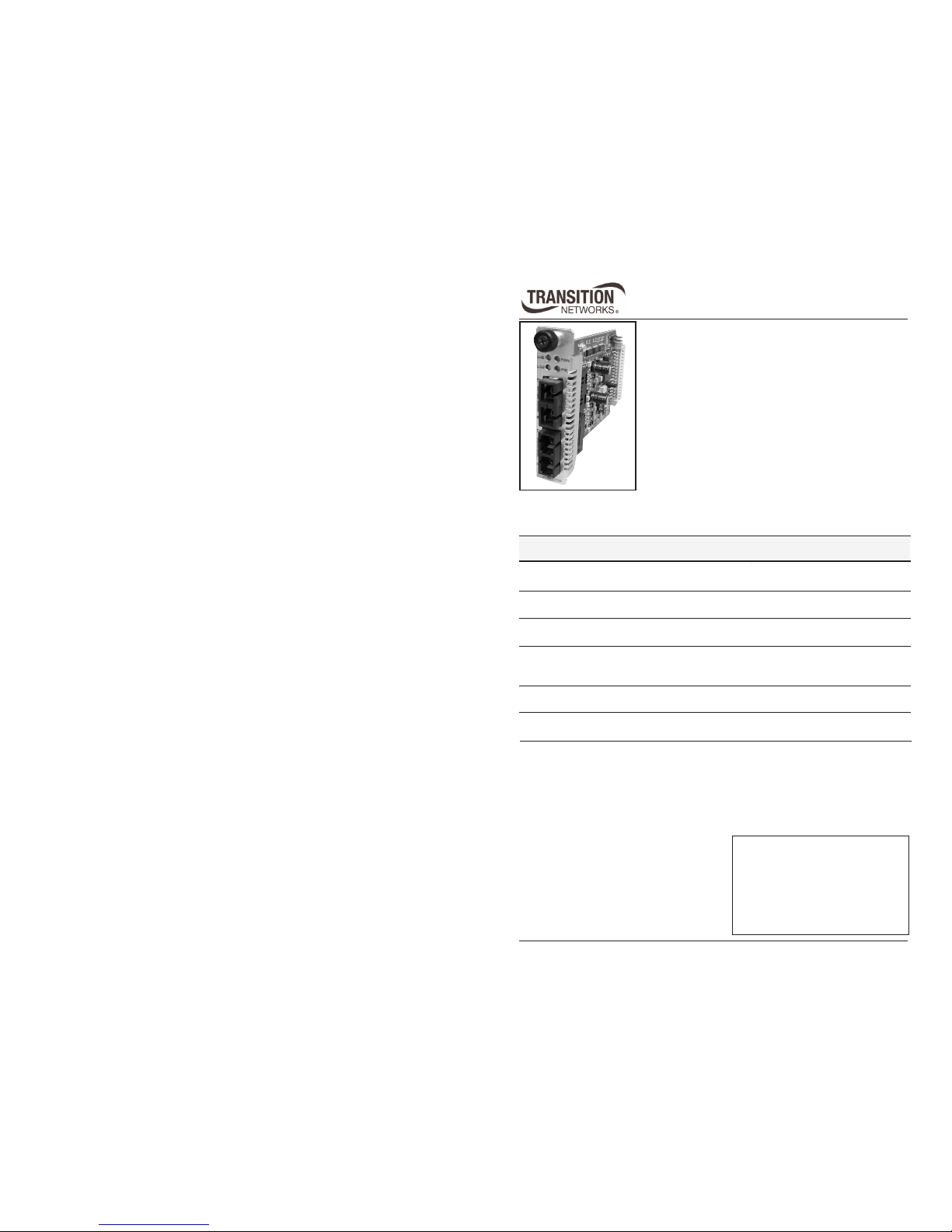
CFMFF13xx-28x
User’s Guide
Single Mode to Multimode Retiming Media
Converter
• Slide-in-Module Media Converter
• Gigabit Ethernet
Transition Networks CFMFF13xx-28x series media
converters extend multimode interfaces over gigabit
Ethernet fiber optic cable. The CFMFF13xx-28x is also
designed to be installed into the Transition Networks
PointSystem™ chassis.
Unlike most gigabit Ethernet media converters, which allow only two media
converters in series, the CFMFF13xx-28x has a retiming/reshaping feature that
makes it possible to connect any number of media converters in series.
Part Number
Port One - Duplex Fiber Optic
1000Base-SX
Port Two - Duplex Fiber-Optic
1000Base-LX
CFMFF1314-280 SC, 850 nm multimode
220 m (721 ft)**
SC, 1310 nm single mode
10 km (6.2 miles)
CFMFF1315-280 SC, 850 nm multimode
220 m (721 ft)**
SC, 1310 nm single mode
25 km (15.5 miles)
CFMFF1317-280 SC, 850 nm multimode
220 m (721 ft)**
SC, 1550 nm single mode
65 km (40.3 miles)
CFMFF1324-280 SC, 850 nm multimode
220 m (721 ft)**
SC, 1300 nm multimode
(1000Base-SX) 2 km (1.2 miles)
(62.5 / 125 mm fiber only)
CFMFF1335-280 SC, 850 nm multimode
220 m (721 ft)**
SC, 1550 nm single mode
125 km (77.5 mi)
CFMFF3535-280 SC, 1550 nm single mode
125 km (77.5 mi)
SC, 1550 nm single mode
125 km (77.5 mi)
NOTE: The SFMFF13xx-28x model is the
stand alone version of the media converter.
For more information, see the user’s guide
on-line at: www.transition.com.
Page 2
Port One - Duplex Fiber Optic
1000Base-SX
Port Two - Single Mode Fiber-Optic
Single Fiber, 1000Base-LX
2
CFMFF13xx-28x
24-hour Technical Support: 1-800-260-1312 -- International: 00-1-952-941-7600
Part Number
CFMFF1329-280 SC, 850 nm multimode
220 m (721 ft)**
SC, 1310 nm (TX)/1550 nm (RX)
20 km (12.4 miles)
CFMFF1329-281 SC, 850 nm multimode
220 m (721 ft)**
SC, 1550 nm (TX)/1310 nm (RX)
20 km (12.4 miles)
CFMFF1329-280 and CFMFF1329-281 are intended to be
installed in the same network where one is the local converter
and the other is the remote converter.
CFMFF1329-282 SC, 850 nm multimode
220 m (721 ft)**
SC, 1310 nm (TX)/1550 nm (RX)
40 km (24.8 miles)
CFMFF1329-283 SC, 850 nm multimode
220 m (721 ft)**
SC, 1550 nm (TX)/1310 nm (RX)
40 km (24.8 miles)
Unless otherwise indicated, the distances listed are the typical maximum cable
distance. The actual maximum cable distances are dependent upon the physical
characteristics of the network installation. TX = transmit, RX = receive.
** Minimum Cable Distance: 2 meters
Typical Maximum Cable Distance: 220 meters for 160/500MHz•Km
270 meters for 200/500MHz•Km
CFMFF1329-282 and CFMFF1329-283 are intended to be
installed in the same network where one is the local converter
and the other is the remote converter.
Installation
CAUTION: Wear a grounding device and observe electrostatic discharge
precautions when setting the jumper, the 4-position switch, and when installing
the slide-in-module. Failure to observe this caution could result in damage to,
and subsequent failure of, the media converter.
Set the Hardware/Software Jumper
• The jumper is located on the circuit board.
• Use small needle-nose pliers to set the recessed switches.
Hardware The media converter mode is determined by the
4-position switch settings (see page 4).
Software The media converter mode is determined by the
most-recently saved, on-board microprocessor
settings. (See SNMP on page 6.)
CFMFF1414-280 SC, 1310 nm single mode
10 km (6.2 miles)
SC, 1310 nm single mode
10 km (6.2 miles)
3
techsupport@transition.com -- Click the “Transition Now” link for a live Web chat.
Installation -- Continued
Set the 4-position switch
• The 4-position switch is located on the circuit board.
• Use a small flat-blade screwdriver to set the recessed switches.
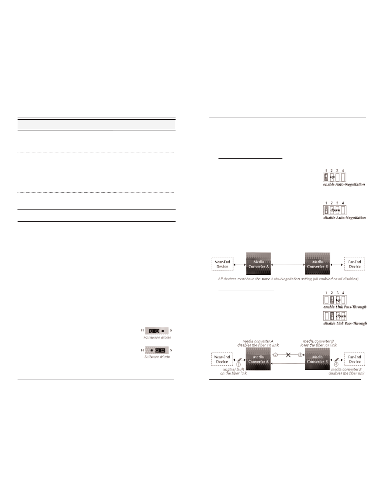
Fiber Auto-Negotiation
(Switch 1)
up = Enable fiber Auto-Negotiation for both the single mode and the
multimode ports.
When fiber Auto-Negotiation is enabled:
The pause feature can be set using switches
3 and 4. (See page 4).
down = Disable fiber Auto-Negotiation for both the single mode and the
multimode ports.
When fiber Auto-Negotiation is disabled:
Switches 3 and 4 will not function. The
media converter adopts the pause setting
from the end device at the other end of the
fiber cable.
NOTE: All devices in the network, including the end devices, must have
Auto-Negotiation enabled, or all devices must have Auto-Negotiation
disabled. Otherwise, the devices in the network will not link up.
Link Pass-Through (Switch 2)
up = Enable Link Pass-Through.
down = Disable Link Pass-Through.
The Link Pass-Through feature allows the media
converter to monitor both fiber RX (receive) ports for
loss of signal. In the event of a loss of an RX signal
on one media port, the media converter will
automatically disable the TX (transmit) signal of the
other media port, thus, “passing through” the link loss.
Page 3
No Pause:
• Pause feature is disabled.
Transmit Only:
• CFMFF13xx-28x can transmit and the
link partner can receive the pause
signal.
Transmit and Receive:
• Both the CFMFF13xx-28x and the
link partner can send and receive the
pause signal.
Receive Only:
• The CFMFF13xx-28x can receive and
the link partner can transmit the
pause signal.
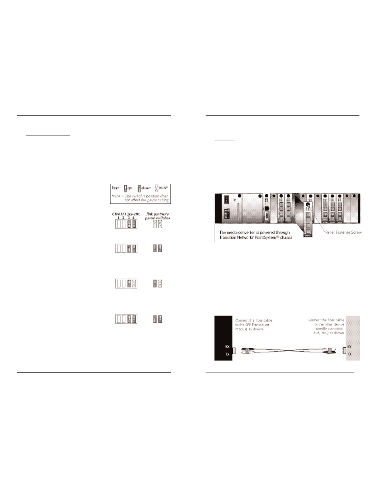
Installation -- Continued
Pause (Switches 3 & 4)
The pause feature can improve network performance by allowing one end of
the link to signal the other to discontinue frame transmission for a set period
of time to relieve buffer congestion.
To properly set the pause feature in the network, the link partner (i.e., the
device to which the CFMFF13xx-28x is linked) must also have comparable
pause switches. If the link partner does not have the pause feature, disable
the pause feature on the CFMFF13xx-28x media converter.
The CFMFF13xx-28x has four pause
options (listed below). To the right of
each option, a drawing shows the switch
settings for the CFMFF13xx-28x and the
link partner.
4
CFMFF13xx-28x
24-hour Technical Support: 1-800-260-1312 -- International: 00-1-952-941-7600
5
techsupport@transition.com -- Click the “Transition Now” link for a live Web chat.
Install the Fiber Cable
1. Locate or build IEEE 802.3™ compliant fiber cable with male, twostranded TX to RX connectors installed at both ends.
2. Connect the fiber cables to the CFMFF13xx-28x media converter as
described:
• Connect the male TX cable connector to the female TX port.
• Connect the male RX cable connector to the female RX port.
3. Connect the fiber cables to the other device (another media converter,
hub, etc.) as described:
• Connect the male TX cable connector to the female RX port.
• Connect the male RX cable connector to the female TX port.
Installation -- Continued
Install the CFMFF13xx-28x Slide-in-Module
CAUTION: Slots in the PointSystem™ chassis without a slide-in-module
installed MUST have a protective plate covering the empty slot for Class A
and/or Class B compliance.
The media converter slide-in-modules may be installed in any slot, in any
order. To install the CFMFF13xx-28x slide-in-module:
1. Carefully slide the slide-in-module into the installation slot, aligning the
module’s circuit board with the installation guides.
2. Ensure that the module is firmly seated inside the chassis.
3. Push in and rotate the attached panel fastener screw clockwise to secure
the module to the chassis front.
Page 4

6
CFMFF13xx-28x
24-hour Technical Support: 1-800-260-1312 -- International: 00-1-952-941-7600
SNMP
Use SNMP at an attached terminal or at a remote location to monitor the
media converter by monitoring:
• Media converter power
• Single mode fiber link status
• Multimode fiber link status
• Hardware/software mode status
Also, use SNMP to enter network commands that:
• Power up/down the media converter
• Enable/disable the single mode fiber link
• Enable/disable the multimode fiber link
• Enable/disable Auto-Negotiation
• Enable/disable Link Pass-Through
• Select pause advertisements
See the on-line documentation that comes with Transition Networks
FocalPoint™ software for applicable commands and usage at
www.transition.com.
Operation
Status LEDs
Use the status LEDs to monitor the media converter operation in
the network.
PWR On = Connection to external power.
LKS On = 1000Base-LX (single mode) fiber link is up.
LKM On = 1000Base-SX (multimode) fiber link is up.
ACT Flashing = Reception of data on either fiber link.
7
techsupport@transition.com -- Click the “Transition Now” link for a live Web chat.
Cable Specifications
The physical characteristics must meet or exceed IEEE 802.3™ specifications.
Single Mode fiber (recommended): 9 µm
Multimode fiber (recommended): 62.5/125 µm
Multimode fiber (optional): 100/140, 85/140, 50/125 µm
Bit error rate:
<10
-12
Port 1: 1300 nm multimode
Fiber-optic Transmitter Power: min: -10.0 dBm max: -4.0 dBm
Fiber-optic Receiver Sensitivity: min: -17.0 dBm max: 0.0 dBm
Link Budget: 7.0 dB
Port 2:
CFMFF1314-280 1310 nm single mode
Fiber-optic Transmitter Power: min: -13.0 dBm max: -3.0 dBm
Fiber-optic Receiver Sensitivity: min: -20.0 dBm max: -3.0 dBm
Link Budget: 7.0 dB
CFMFF1315-280 1310 nm single mode
Fiber-optic Transmitter Power: min: -5.0 dBm max: 0.0 dBm
Fiber-optic Receiver Sensitivity: min: -20.0 dBm max: -3.0 dBm
Link Budget: 15.0 dB
CFMFF1317-280 1550 nm single mode
Fiber-optic Transmitter Power: min: -3.0 dBm max: +2.0 dBm
Fiber-optic Receiver Sensitivity: min: - 23.0 dBm max: -3.0 dBm
Link Budget: 20.0 dB
CFMFF1324-280 1300 nm extended multimode
Fiber-optic Transmitter Power: min: -10.0 dBm max: -3.0 dBm
Fiber-optic Receiver Sensitivity: min: -17.0 dBm max: -3.0 dBm
Link Budget: 7.0 db
CFMFF1329-280 1310 nm (TX) / 1550 nm (RX) single mode
Fiber-optic Transmitter Power: min: -8.0 dBm max: -3.0 dBm
Fiber-optic Receiver Sensitivity: min: -21.0 dBm max: -3.0 dBm
Link Budget: 13.0 dB
CFMFF1329-281 1550 nm (TX) / 1310 nm (RX) single mode
Fiber-optic Transmitter Power: min: -8.0 dBm max: -3.0 dBm
Fiber-optic Receiver Sensitivity: min: -21.0 dBm max: -3.0 dBm
Link Budget: 13.0 dB
CFMFF1329-282 1310 nm (TX) / 1550 nm (RX) single mode
Fiber-optic Transmitter Power: min: -3.0 dBm max: +2.0 dBm
Fiber-optic Receiver Sensitivity: min: -23.0 dBm max: -8.0 dBm
Link Budget: 20.0 dB
CFMFF1329-283 1550 nm (TX) / 1310 nm (RX) single mode
Fiber-optic Transmitter Power: min: -3.0 dBm max: +2.0 dBm
Fiber-optic Receiver Sensitivity: min: -23.0 dBm max: -8.0 dBm
Link Budget: 20.0 dB
CFMFF1335-280 1550 nm single mode
Fiber-optic Transmitter Power: min: 0.0 dBm max: +5.0 dBm
Fiber-optic Receiver Sensitivity: min: -32.0 dBm max: -3.0 dBm
Link Budget: 32.0 db
Page 5

8
CFMFF13xx-28x
24-hour Technical Support: 1-800-260-1312 -- International: 00-1-952-941-7600
Technical Specifications
For use with Transition Networks Model CFMFF13xx-28x or equivalent
Standards: IEEE 802.3™ 2000 (802.3z)
Dimensions: 3.4" x 0.86" x 5.0" (86 mm x 22mm x 127mm)
Weight 5 oz (141 g) (approximate)
Data Rate 1000 Mb/s
Delay Time 184 ns
Power Consumption 3.6 watts (typical)
Environment Tmra*: 0°C to 50°C (32°F to 122°F)
Storage Temp: -15°C to 65°C (5°F to 149°F)
Humidity: 5 to 95%, non condensing
Altitude: 0 to 10,000 feet
Warranty Lifetime
*Manufacturer’s rated ambient temperature: Tmra range for this slide-in-module
depends on the physical characteristics and the installation configuration of the
Transition Networks PointSystem™ chassis in which this slide-in-module will be
installed.
NOTE: Information in this user’s guide is subject to change. For the most up-todate information on the CFMFF13xx-28x media converter, view the user’s guide
on-line at: www.transition.com
Product is certified by the manufacturer to comply with DHHS Rule 21/CFR,
Subchapter J applicable at the date of manufacture.
CAUTION: Visible and invisible laser radiation when open. Do not stare into
beam or view directly with optical instruments.
CAUTION: Use of controls, adjustments or the performance of procedures other
than those specified herein may result in hazardous radiation exposure.
The fiber optic transmitters on this device meet Class I Laser safety requirements
per IEC-825/CDRH standards and complies with 21 CFR1040.10 and
21CFR1040.11.
Cable Specifications -- continued
CFMFF3535-280, Ports 1 & 2 1550 nm single mode
Fiber-optic Transmitter Power: min: 0.0 dBm max: +5.0 dBm
Fiber-optic Receiver Sensitivity: min: -27.0 dBm max: -3.0 dBm
Link Budget: 27.0 db
CFMFF1414-280, Port 2 1310 nm single mode
Fiber-optic Transmitter Power: min: -13.0 dBm max: -3.0 dBm
Fiber-optic Receiver Sensitivity: min: -20.0 dBm max: -3.0 dBm
Link Budget: 7.0 dB
9
techsupport@transition.com -- Click the “Transition Now” link for a live Web chat.
Troubleshooting
If the media converter fails, isolate and correct the fault by determining the
answers to the following questions and then taking the indicated action:
1. Is the PWR (power) LED illuminated?
NO
• Is the media converter inserted properly into the chassis?
• Is the power cord properly installed in the chassis and at the external
power source?
• Does the external power source provide power?
• Contact Technical Support. US/Canada: 1-800-260-1312,
International: 00-1-952-941-7600.
YES
• Proceed to step 2.
2. Are the Auto-Negotiation switches on the network devices set
such that all are set to “enable” or all are set to “disable”?
NO
• Set the Auto-Negotiation switches on all of the devices (including the
end devices) so that all are set to “enable” or all are set to “disable.”
(See page 3 to set the Auto-Negotiation switch on the media
converter.)
• Contact Technical Support. US/Canada: 1-800-260-1312,
International: 00-1-952-941-7600.
YES
• Proceed to step 3.
3. Is the LKS (link, single mode) LED illuminated?
NO
• Check the single mode fiber cables for proper connection.
• Verify that the TX and RX cables on the media converter are
connected to the RX and TX ports, respectively, on the other device.
• Contact Technical Support. US/Canada: 1-800-260-1312,
International: 00-1-952-941-7600.
YES
• Proceed to step 4.
4. Is the LKM (link, multimode) LED illuminated?
NO
• Check the multimode fiber cables for proper connection.
• Verify that the TX and RX cables on the media converter are
connected to the RX and TX ports, respectively, on the other device.
• Contact Technical Support. US/Canada: 1-800-260-1312,
International: 00-1-952-941-7600.
YES
• Proceed to step 5.
Page 6

10
CFMFF13xx-28x
24-hour Technical Support: 1-800-260-1312 -- International: 00-1-952-941-7600
Troubleshooting -- Continued
5. Is the ACT (fiber activity) LED flashing?
NO
• If there is activity on the single mode fiber link, disconnect and
reconnect the fiber cable on the single mode port to restart the
initialization process.
• If there is activity on the multimode fiber link, disconnect and
reconnect the fiber cable on the multimode port to restart the
initialization process.
• If there is no activity on either fiber link, contact Tech Support:
1-800-260-1312, Int’l: 00-1-952-941-7600.
YES
• Contact Tech Support: 1-800-260-1312, Int’l: 00-1-952-941-7600.
11
techsupport@transition.com -- Click the “Transition Now” link for a live Web chat.
Contact Us
Technical Support
Technical support is available 24 hours a day.
US and Canada: 1-800-260-1312
International: 00-1-952-941-7600
Transition Now
Chat live via the Web with Transition Networks Technical Support.
Log onto www.transition.com and click the Transition Now link.
Web-Based Seminars
Transition Networks provides seminars via live web-based training.
Log onto www.transition.com and click the Learning Center link.
E-Mail
Ask a question anytime by sending an e-mail to our technical support staff.
techsupport@transition.com
Address
Transition Networks
6475 City West Parkway
Minneapolis, MN 55344, U.S.A.
telephone: 952-941-7600
toll free: 800-526-9267
fax: 952-941-2322
Declaration of Conformity
Name of Mfg: Transition Networks
6475 City West Parkway, Minneapolis MN 55344 U.S.A.
Model: CFMFF13xx-28x Series Media Converters
Part Number(s): CFMFF1314-280, CFMFF1315-280, CFMFF1317-280, CFMFF1324-280,
CFMFF1335-280, CFMFF3535-280, CFMFF1329-280, CFMFF1329-281,
CFMFF1329-282, CFMFF1329-283, CFMFF1414-280
Regulation: EMC Directive 89/336/EEC
Purpose: To declare that the CFMFF13xx-28x series and CFMFF1414-280 to
which this declaration refers is in conformity with the following standards.
EN 55022:1994, A-1:1995, A-2:1997 Class A; FCC Part 15 Subpart B;
21CFR subpart J
I, the undersigned, hereby declare that the equipment specified above conforms to the above
Directive(s) and Standard(s).
November 2007_____
Stephen Anderson, Vice-President of Engineering Date
Page 7

Trademark Notice
All registered trademarks and trademarks are the property of their respective owners.
Copyright Restrictions
© 2004 Transition Networks. All rights reserved.
No part of this work may be reproduced or used in any form or by any means - graphic,
electronic, or mechanical - without written permission from Transition Networks.
Compliance Information
CISPR22/EN55022 Class A
CE Mark
UL Listed
C-UL Listed
FCC Regulations
This equipment has been tested and found to comply with the limits for a Class A digital
device, pursuant to part 15 of the FCC rules. These limits are designed to provide reasonable
protection against harmful interference when the equipment is operated in a commercial
environment. This equipment generates, uses, and can radiate radio frequency energy and, if
not installed and used in accordance with the instruction manual, may cause harmful
interference to radio communications. Operation of this equipment in a residential area is
likely to cause harmful interference, in which case the user will be required to correct the
interference at the user's own expense.
Canadian Regulations
This digital apparatus does not exceed the Class A limits for radio noise for digital apparatus
set out on the radio interference regulations of the Canadian Department of Communications.
Le présent appareil numérique n'émet pas de bruits radioélectriques dépassant les limites
applicables aux appareils numériques de la Class A prescrites dans le Règlement sur le
brouillage radioélectrique édicté par le ministère des Communications du Canada.
European Regulations
Warning This is a Class A product. In a domestic environment this product may cause radio
interference in which case the user may be required to take adequate measures.
Achtung! Dieses ist ein Gerät der Funkstörgrenzwertklasse A. In Wohnbereichen können bei
Betrieb dieses Gerätes Rundfunkstörungen auftreten. In diesem Fäll ist der Benutzer für
Gegenmaßnahmen verantwortlich.
Attention! Ceci est un produit de Classe A. Dans un environment domestique, ce produit
risque de créer des interférences radioélectriques, il appartiendra alors à l'utilsateur de
prende les measures spécifiques appropriées.
In accordance with European Union Directive 2002/96/EC of the European
Parliament and of the Council of 27 January 2003, Transition Networks will
accept post usage returns of this product for proper disposal. The contact
information for this activity can be found in the 'Contact Us' portion of this
document.
Printed in the U.S. A. 33298.C
12
CFMFF13xx-28x
 Loading...