

Transition Networks C/E-TBT-FRL-03(L), C/E-TBT-FRL-03(MT), C/E-TBT-FRL-03(SC), C/E-TBT-FRL-03(SM), C/E-TBT-FRL-03(XC) User Manual
...Page 1
COMPLIANCE INFORMATION
UL Listed
C-UL Listed (Canada)
CISPR/EN55022 Class A
FCC Regulations
This equipment has been tested and found to comply with the limits for a class A digital device, pursuant
to part 15 of the FCC rules. These limits are designed to provide reasonable protection against harmful
interference when the equipment is operated in a commercial environment. This equipment generates,
uses, and can radiate radio frequency energy and, if not installed and used in accordance with the
instruction manual, may cause harmful interference to radio communications. Operation of this
equipment in a residential area is likely to cause harmful interference, in which case the user will be
required to correct the interference at the user’s own expense.
Canadian Regulations
This digital apparatus does not exceed the Class A limits for radio noise for digital apparatus set out on
the radio interference regulations of the Canadian Department of Communications.
Le présent appareil numérique n'émet pas de bruits radioélectriques dépassant les limites applicables
aux appareils numériques de la class A prescrites dans le Règlement sur le brouillage radioélectrique
édicté par le ministère des Communications du Canada.
European Regulations
Warning
This is a Class A product. In a domestic environment this product may cause radio interference in which
case the user may be required to take adequate measures.
Achtung !
Dieses ist ein Gerät der Funkstörgrenzwertklasse A. In Wohnbereichen können bei Betrieb dieses Gerätes
Rundfunkstörungen auftreten, in weichen Fällen der Benutzer für entsprechende Gegenmaßnahmen
werantwortlich ist.
Attention !
Ceci est un produit de Classe A. Dans un environment domestique, ce produit risque de créer des
interférences radioélectriques, il appartiendra alors à l’utilsateur de prende les measures spécifiques
appropriées
Copyright Restrictions
© 1999 TRANSITION Networks.
All rights reserved. No part of this work may be reproduced or used in any form or by any means –
graphic, electronic, or mechanical – without written permission from TRANSITION Networks.
Trademark Notice
All registered trademarks and trademarks are the property of their respective owners.
Printed in the U.S.A. 33049.F
Designed to be installed in the TRANSITION Networks E-MCC-1600 Media
Converter Chassis, C/E-TBT-FRL-03
series 10BASE-T/10BASE-FL media
converters connect either halfduplex or full-duplex, unshielded or
shielded 10BASE-T twisted-pair
copper to either half-duplex or fullduplex 10BASE-FL multimode fiber.
CAUTION: RJ connectors are NOT INTENDED FOR CONNECTION TO THE
PUBLIC TELEPHONE NETWORK. Failure to observe this caution could result in
damage to the public telephone network.
Der Anschluss dieses Gerätes an ein öffentlickes Telekommunikationsnetz in den EG-Mitgliedstaaten
verstösst gegen die jeweligen einzelstaatlichen Gesetze zur Anwendung der Richtlinie 91/263/EWG zur
Angleichung der Rechtsvorschriften der Mitgliedstaaten über Telekommunikationsendeinrichtungen
einschliesslich der gegenseitigen Anerkennung ihrer Konformität.
Minneapolis, MN 55344 USA
10BASE-T/10BASE-FL
Slide-In-Module Media Converters
C/E-TBT -FRL-03, C/E-TBT -FRL-03(SC), C/E-TBT -FRL-03(SM),
C/E-TBT-FRL-03(L), C/E-TBT-FRL-03(MT), C/E-TBT-FRL-03(XC)
USER’S GUIDE
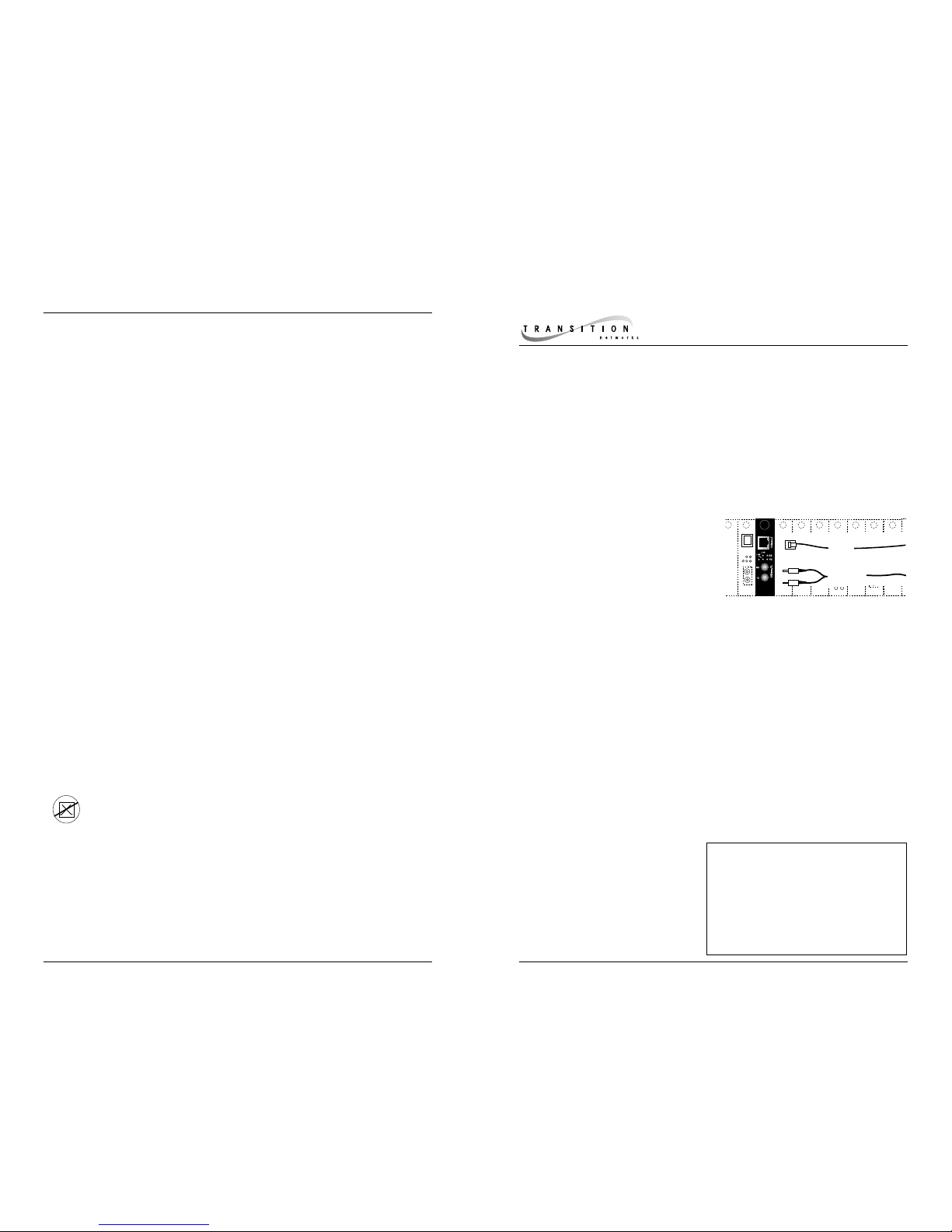
C/E-TBT-FRL-03
Provides an RJ-45 unshielded twisted
pair 10BASE-T connector and a set of
RX (receive) and TX (transmit) ST
10BASE-FL 850nm multimode fiber
connectors.
C/E-TBT-FRL-03 (SC)
Provides an RJ-45 unshielded twisted
pair 10BASE-T connector and a set of
RX (receive) and TX (transmit) SC
10BASE-FL 850nm multimode fiber
connectors.
C/E-TBT-FRL-03(SM)
Provides an RJ-45 unshielded twisted
pair 10BASE-T connector and an RX
(receive) and TX (transmit) ST 10BASEFL 1300nm singlemode fiber
connector.
C/E-TBT-FRL-03(L)
Provides an RJ-45 unshielded twisted
pair 10BASE-T connector and a set of
RX (receive) and TX (transmit) ST
10BASE-FL 1300nm multimode fiber
connectors.
C/E-TBT-FRL-03(MT)
Provides an RJ-45 unshielded twisted
pair 10BASE-T connector and an RX
(receive) and TX (transmit) MT-RJ
10BASE-FL 850nm multimode fiber
connector.
C/E-TBT-FRL-03(XC)
Provides an RJ-45 unshielded twisted
pair 10BASE-T connector and an RX
(receive) and TX (transmit) SC 10BASEFL 1300nm singlemode fiber connector.
C/E-TBT-FRL-03 in the Network .2
Installation . . . . . . . . . . . . . . . . .3
Operation . . . . . . . . . . . . . . . . . .4
Fault Isolation and Correction . .5
Cable Specifications . . . . . . . . . .6
Technical Specifications . . . . . . .7
Compliance Information . . . . . . .8
850nm
Multimode
Fiber
10BASE-T
Copper
Ethernet
TM
C/E-TBT-FRL-03
P
C/E-TBT-FRL-03
Page 2
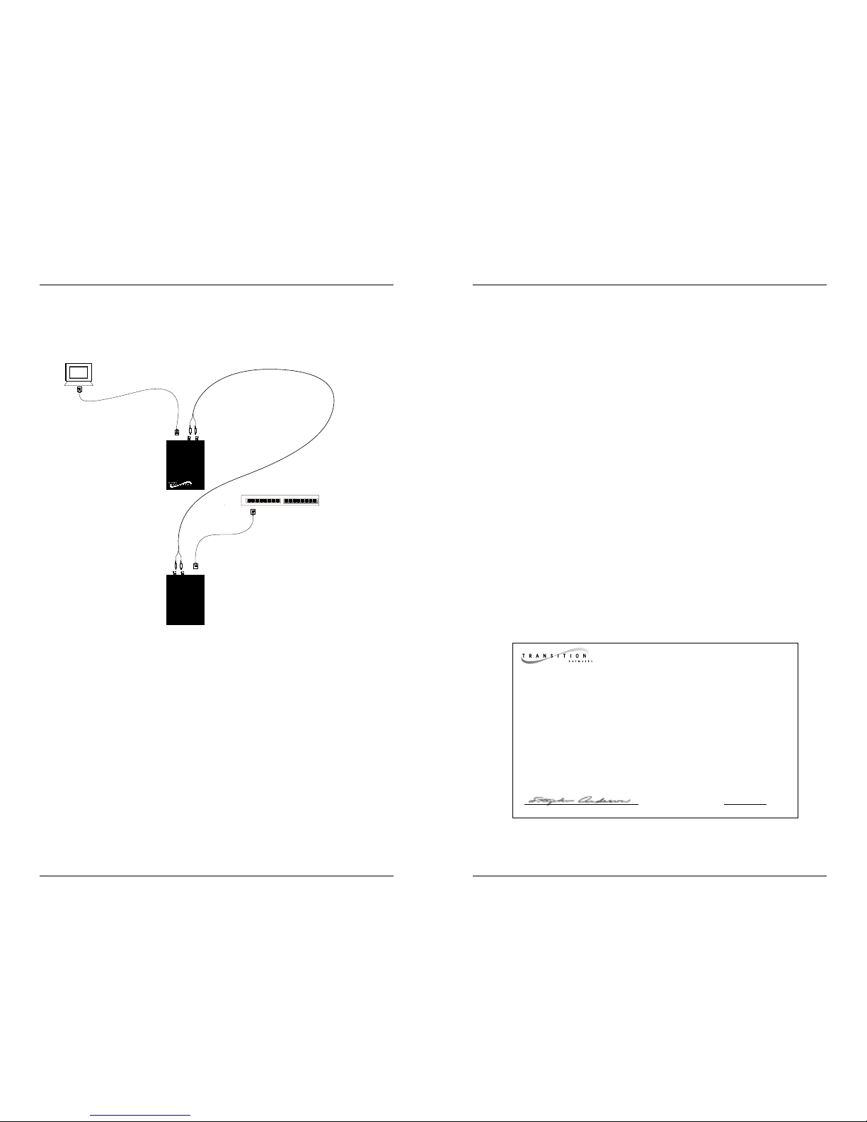
C/E-TBT-FRL-03 IN THE NETWORK
Use the C/E-TBT-FRL-03 media converter (or two C/E-TBT-FRL-03 media
converters in pairs) to connect a workstation to a remote hub or to connect two
hubs.
NOTE: Maximum cable distances apply ONLY to full duplex installations.
TECHNICAL SPECIFICATIONS
Standards IEEE 802.3
Case Dimensions 3.8" x 2.4" x 1.0" (97mm x 61mm x 25mm)
Environment Temperature: 0-50°C (32° to 122° F )
Humidity 5-95%, non condensing
Altitude 0-10,000 feet
Australia
Warranty Lifetime
DECLARATION OF CONFORMITY
Name of Mfg: Transition Networks
6475 City West Parkway, Minneapolis MN 55344 USA
Model: C/E-TBT-FRL-03 Series Copper-to-Fiber Media Converter
Part Number: C/E-TBT-FRL-03, C/E-TBT-FRL-03(SC), C/E-TBT-FRL-03(SM),
C/E-TBT-FRL-03(L), C/E-TBT-FRL-03(MT), C/E-TBT-FRL-03(XC)
Regulation: EMC Directive 89/336/EEC
Purpose: To declare that the C/E-TBT-FRL-03 to which this declaration refers is
in conformity with the following standards.
EMC-CISPR 22: 1985 Class A; EN 55022: 1988 Class A; EN 50082-1:1992;
EN 60950 A4:1997; IEC 801.2, IEC 801.3, and IEC 801.4; IEC 950
I, the undersigned, hereby declare that the equipment specified above conforms to the
above Directive(s) and Standard(s).
_July 7, 1999_____
Stephen Anderson, Vice-President of Engineering Date
2 kilometers - 850 nM multimode
100 meters
100 meters
20 kilometers - 1300 nM singlemode
5 kilometers - 1300 nM multimode
Page 3

CABLE SPECIFICATIONS
The physical characteristics of the media cable must meet or exceed IEEE 802.3
specifications.
Fiber Cable
850NM MULTIMODE
Fiber Optic Cable Recommended: 62.5 / 125 µm multimode fiber
Fiber Optic Transmitter Power: Minimum: -15 dBm
Fiber Optic Receiver Sensitivity: Minimum : -33 dBm
Bit error rate: ≤10
-10
Maximum Cable Distance: 2 kilometers (6,600 feet
1300NM MULTIMODE
Fiber Optic Cable Recommended: 62.5 / 125 µm multimode fiber
Fiber Optic Transmitter Power: Minimum: -17 dBm
Fiber Optic Receiver Sensitivity: Minimum: -35 dBm
Bit error rate: ≤10
-9
Maximum Cable Distance: 5 kilometers (16,500 feet)
1300NM SINGLEMODE (ST)
Fiber Optic Cable Recommended: 9/125 micron single mode fiber
Fiber Optic Transmitter Power: Minimum: -27 dBm
Fiber Optic Receiver Sensitivity: Minimum: -36 dBm
Bit error rate: ≤10
-10
Maximum Cable Distance: 20 kilometers (66,000 feet)
1300NM SINGLEMODE (SC)
Fiber Optic Cable Recommended: 62.5 / 125 µm multimode fiber
Fiber Optic Transmitter Power: Minimum: -15.5 dBm
Fiber Optic Receiver Sensitivity: Minimum : -36.9 dBm
Bit error rate: ≤10
-10
Maximum Cable Distance: 20 kilometers (66,000 feet)
Copper Cable and Connector
Category 3 or better twisted-pair copper wire is required. Either shielded twisted-pair (STP) or
unshielded twisted-pair (UTP) can be used. DO NOT USE FLAT OR SILVER SATIN WIRE.
CATEGORY 3:
Gauge 24 to 22 AWG
Attenuation £11.5 dB/100m @ 5-10 MHz
Maximum Number of Nodes 2 nodes
Maximum Cable Distance 100 meters (200 meters with better cable
RJ-45 Pin-outs Pin 1=TD+, Pin 2=TD-,
Pin 3=RTD+, Pin 4=RD-
Twisted pair connection requires two active
pairs configured as straight through. The two
active pairs in an Ethernet™ network are pins
1 & 2 and pins 3 & 6. Use only dedicated wire
pairs (such as blue/white & white/blue,
orange/white & white/orange) for the active
pairs.
INSTALLA TION
Set MDI/MDI-X Switch
NOTE: Straight-through/crossover 10BASE-T requirements are satisfied using
the MDI/MDI-X switch with
straight-through cable. See
page 6 for cable
configurations.
Using small flatblade screwdriver or similar tool and referring to label at front
of media converter, set MDI/MDI-X switch position for site installation.
10BASE-T cable connections between a hub and the media converter
require the MDI/MDI-X switch to be set to MDI. 10BASE-T cable
connections between the media converter and a terminal, transceiver or
NIC require the switch to be set to MDI-X
Install Slide-In-Module in E-MCC-1600 Chassis
NOTE: Media Converter Slide-in-Modules can be installed in any
installation slot, in any order.
• Remove Media Converter Slide-in-Module protective plate from
selected installation slot by removing two (2) screws that secure
plate to front of E-MCC-1600.
• Carefully slide Media Converter Slide-in-Module into installation
slot, aligning Media Converter Slide-in-Module with installation
guides.
NOTE: Ensure that the Media Converter Slide-in-Module is firmly seated
against the backplane.
• Secure Slide-in-Module by securing panel fastener screw attached
to Slide-in-Module to E-MCC-1600 chassis.
Install Cable
NOTE: See page 6 for cable specifications.
COPPER
NOTE: KEEP TWISTED PAIR RUNS AS SHORT AS POSSIBLE.
• Locate or build 10BASE-T-compliant cables with straight-through
or crossover configuration and with male RJ-45 plug connectors
at both ends.
• Connect male RJ-45 plug connector at one end of cable to media
converter RJ-45 jack connector.
• Connect male RJ-45 plug connector at other end of cable to
10BASE-T terminal device RJ-45 jack connector (using straightthrough cable configuration) or to 10BASE-T hub RJ-45 jack
connector (using crossover cable configuration).
(continued on next page)
Twisted
Pair #1
Twisted
Pair #2
Straight Through Cable
MDI-X
position
MDI
position
toward network connectors toward chassis
Page 4

INSTALLA TION
(continued)
FIBER
• Locate or build 10BASE-FL-compliant fiber cable with male twostranded TX to RX connectors at both ends.
• Connect male TX and RX cable connectors at one end of cable to
TX and RX female connectors, respectively, on media converter.
• Connect male TX and RX cable connectors at other end of cable
to RX and TX connectors of 802.3 compliant fiber device.
OPERA TION
After installation, the media converter should function without operator
intervention.
Status LEDs
Use the status LEDs to monitor media converter operation in the network.
Link
(near 10BASE-FL connector) Steady green LED indicates good
10BASE-FL link and normal operation.
Dark LED
indicates lack of
power OR
downed
10BASE-FL link.
RX (Receive -
near
10BASE-FL
connector
) Flashing green
LED indicates data reception
on 10BASE-FL link.
Link
(near 10BASE-T connector) Steady green LED indicates good
10BASE-T link and normal operation.
Dark LED indicates lack of power OR downed 10BASE-T
link.
RX (Receive -
near 10BASE-T connector) Flashing green LED
indicates data reception on 10BASE-T link.
P(o)w(e)r Steady green LED indicates connection to external AC
power.
FAULT ISOLATION and CORRECTION
If the media converter fails, isolate and correct the fault by determining the
answers to the following questions and then taking the indicated action:
1. Is the P(ower) LED on the media converter illuminated?
NO
• Is the media converter inserted properly into the E-MCC-1600
chassis?
• Contact Technical Support at (800) 260-1312/ (800) LAN-WANS.
YES
• Proceed to step 2.
2. Is the green 10BASE-T Link LED illuminated?
NO
• Check twisted pair cables for proper connection.
• Contact Technical Support: (800) 260-1312/(800) LAN-WANS.
YES
• Proceed to step 3.
3. Is the green 10BASE-FL Link LED illuminated?
NO
• Check fiber cables for proper connection.
• Verify that TX and RX cables on media converter are connected to
RX and TX ports, respectively, on other device.
• Contact Technical Support: (800) 260-1312/(800) LAN-WANS.
YES
• Proceed to step 4.
4. Is the amber 10BASE-T RX LED illuminated?
NO
• Restart the workstation to restart the initialization process.
• Contact Technical Support: (800) 260-1312/(800) LAN-WANS.
YES
• Proceed to step 5.
5. Is the amber 10BASE-FL RX LED illuminated?
NO
• Restart the workstation to restart the initialization process.
• Contact Technical Support: (800) 260-1312/(800) LAN-WANS.
YES
• Contact Technical Support: (800) 260-1312/(800) LAN-WANS.
10BASE-T
ST Connectors
RX
TX
Link
RX
Link
RX
Pwr
(Fiber)
Link
RX
Pwr
RX
Link
(RJ-45)
RJ-45 Connector
10BASE-T
10BASE-FL
 Loading...