

Page 1
MEDIA CONVERTER TECHNICAL SPECIFICATIONS
Standards 802.3, 100BASE-SX PMD
Case dimensions 4.75" x 3.0" x 1.0" (119mm x 76mm x 25mm)
Shipping Weight 2 pounds (0.9 kilograms)
Environment Temperature: 0-40°C (32° to 104° F )
Humidity 10-90%, non condensing
Altitude 0-10,000 feet
Warranty Lifetime
CAUTION: RJ connectors are NOT INTENDED FOR CONNECTION TO THE
PUBLIC TELEPHONE NETWORK. Failure to observe this caution could result in
damage to the public telephone network.
Compliance Information
UL Listed
C-UL Listed (Canada)
CISPR/EN55022 Class A
FCC Regulations
This equipment has been tested and found to comply with the limits for a class A digital device, pursuant
to part 15 of the FCC rules. These limits are designed to provide reasonable protection against harmful
interference when the equipment is operated in a commercial environment. This equipment generates,
uses, and can radiate radio frequency energy and, if not installed and used in accordance with the
instruction manual, may cause harmful interference to radio communications. Operation of this
equipment in a residential area is likely to cause harmful interference, in which case the user will be
required to correct the interference at the user’s own expense.
Canadian Regulations
This digital apparatus does not exceed the Class A limits for radio noise for digital apparatus set out on
the radio interference regulations of the Canadian Department of Communications.
European Regulations
Warning
This is a Class A product. In a domestic environment this product may cause radio interference in which
case the user may be required to take adequate measures.
Copyright Restrictions
© 1999 TRANSITION Networks.
All rights reserved. No part of this work may be reproduced or used in any form or by any means –
graphic, electronic, or mechanical – without written permission from TRANSITION Networks.
Trademark Notice
All registered trademarks and trademarks are the property of their respective owners. 33104.B
Der Anschluss dieses Gerätes an ein öffentlickes Telekommunikationsnetz in den EG-Mitgliedstaaten
verstösst gegen die jeweligen einzelstaatlichen Gesetze zur Anwendung der Richtlinie 91/263/EWG zur
Angleichung der Rechtsvorschriften der Mitgliedstaaten über Telekommunikationsendeinrichtungen
einschliesslich der gegenseitigen Anerkennung ihrer Konformität.
Minneapolis, MN 55344 USA
10BASE-T/100BASE-TX to 100BASE-SX
Bridging Media Converter Slide-In Module
C/E-PSW-SX-01, C/E-PSW-SX-01(SC)
USER’S GUIDE
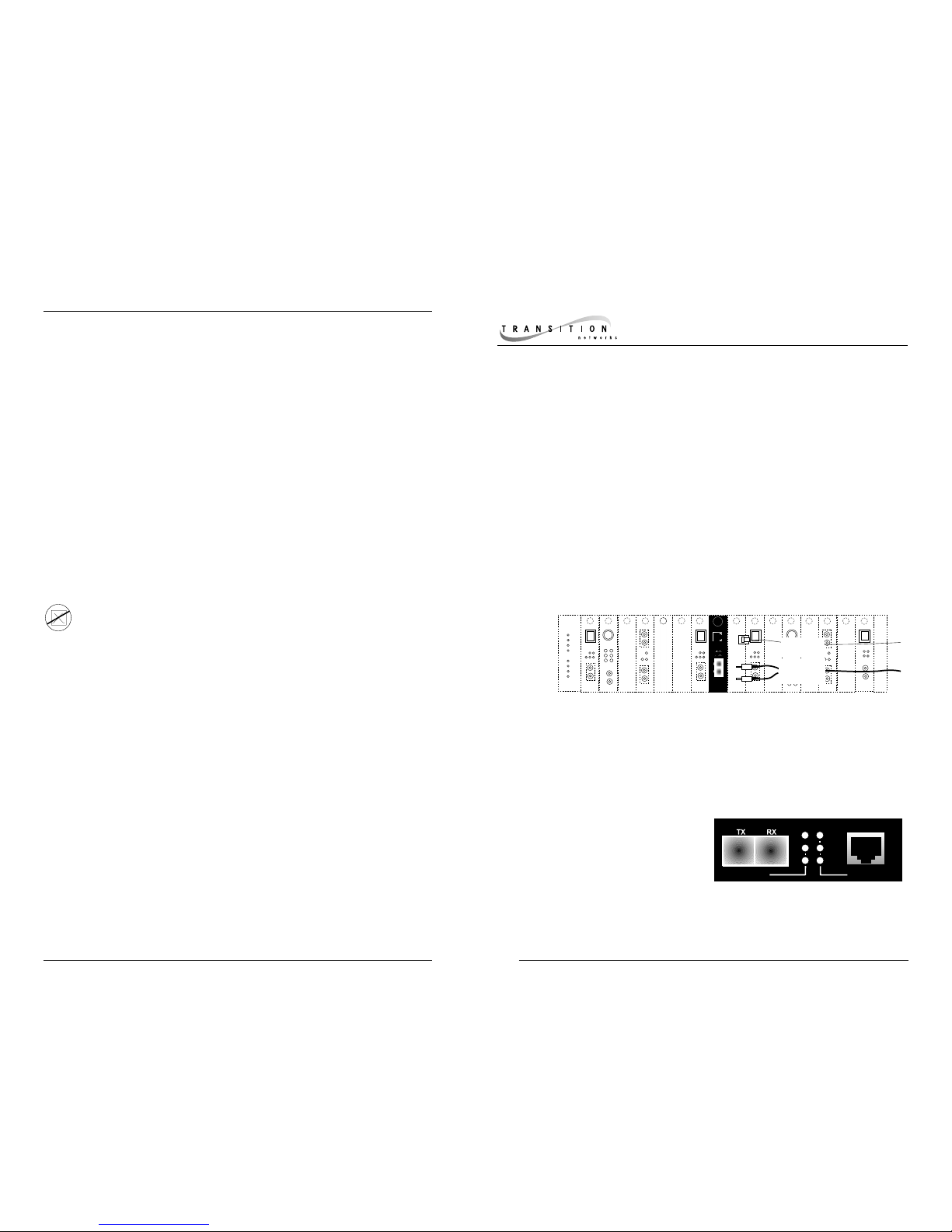
STATUS LEDS
Power Steady green LED indicates
connection to external AC
power.
100 Indicates 100MB/s mode on
UTP/STP.
Link (RECEIVE) Steady green LED indicates UTP/STP OR Fiber link.
Blinking green LED indicates packet reception on UTP/STP OR Fiber
link.
FDX Steady green LED indicates full-duplex operation on UTP/STP
OR on Fiber link.
TRANSITION Networks C/E-PSW-SX-01 series two-port bridging media
converter, designed to be installed in the TRANSITION Networks Media
Conversion Center, E-MCC-1600, segments 10BASE-T/100BASE-TX copper
and 100BASE-SX fiber Ethernet™ collision domains to extend total network
diameter, to reduce network congestion, and to convert between legacy
10BASE-T and 100BASE-SX environments.
A four-position DIP switch located at the side of the media converter allows siteselection of auto-negotiation, of 10MB/s or 100Mb/s speed, and of full-duplex or
half-duplex mode.
C/E-PSW-SX-01
Provides an RJ-45 twisted-pair
connector to UTP/STP copper cable
and a set of RX (receive) and TX
(transmit) ST 850nm multimode
fiber connectors.
C/E-PSW-SX-01(SC)
Provides an RJ-45 twisted-pair
connector to UTP/STP copper
cable and an RX (receive) and TX
(transmit) SC 850nm multimode
fiber connector.
Link
UTP/STP
Fiber
Link
FDX
Power
100
Link
UTP/STP
Fiber
Link
FDX
Power
100
UTP or STP
Copper
850 nm
Multimode
Fiber
Page 2
C/E-PSW-SX-01
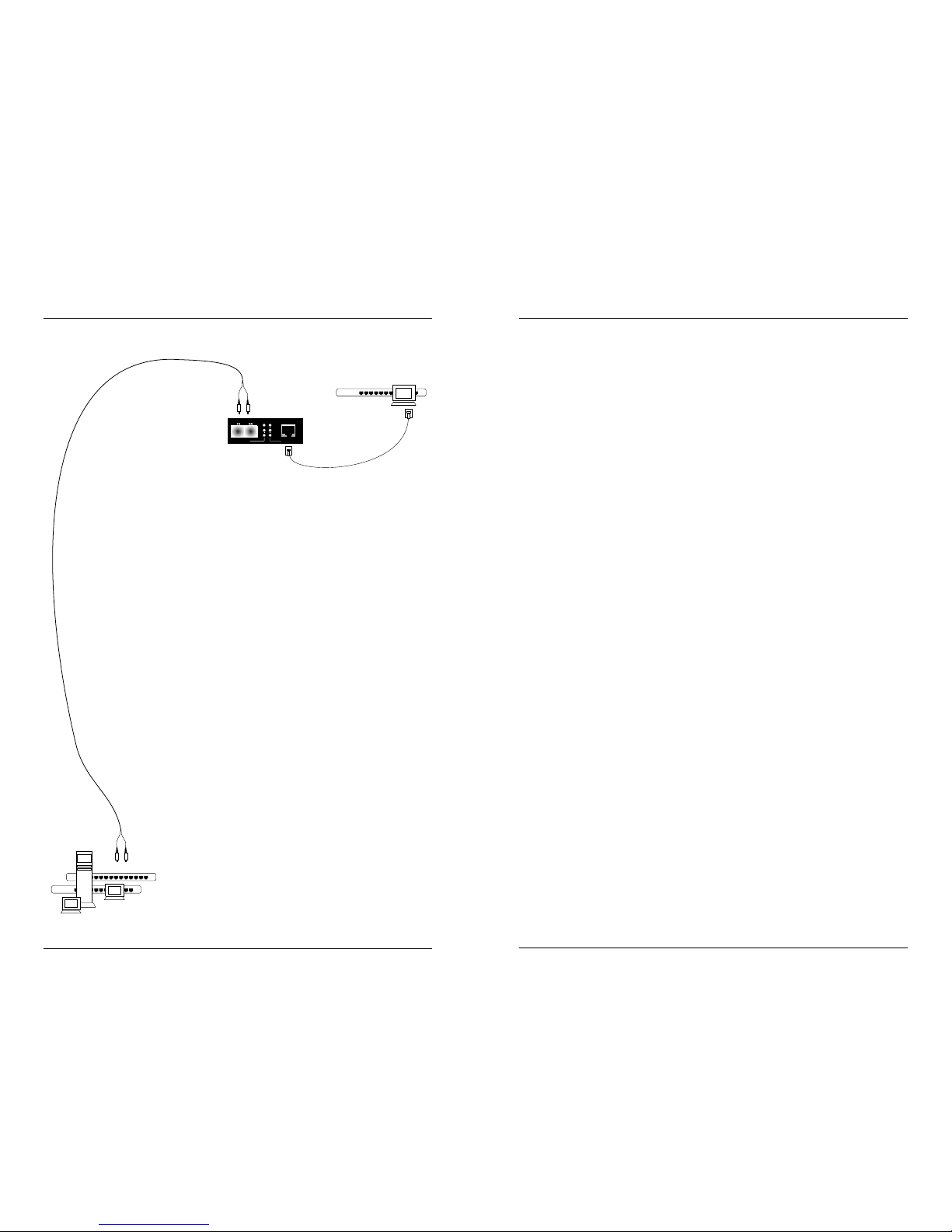
THE C/E-PSW-SX-01 IN THE NETWORK ETHERNET CABLE SPECIFICATIONS
FIBER CABLE SPECIFICATIONS
The physical characteristics of the 100BASE-SX cable must meet or exceed the
100BASE-SX specifications.
MULTIMODE
Fiber-optic Cable Recommended: 62.5 / 125 µm multimode fiber
Optional: 50 / 125 µm multimode fiber
Modal bandwidth: ≤160MHz-Km
Fiber-optic Transmitter Power: min: -20 dBm max: -12 dBm
Fiber-optic Receiver Sensitivity: min: -24 dBm max: -12 dBm
Wavelength: 850nM
Bit error rate: ≤2.5
-10
Maximum Cable Distance: 300 meters
TWISTED-PAIR CABLE SPECIFICATIONS
The physical characteristics of 10BASE-T cable must meet or exceed IEEE 802.3
10BASE-T specifications. Though Category 3 cable is adequate for the 10BASE-T
installation, Category 5 cable is strongly recommended, since Category 3 cable
can NOT be used for a later upgrade to 100BASE-TX. DO NOT USE FLAT OR
SILVER SATIN WIRE.
The physical characteristics of 100BASE-TX cable must meet or exceed IEEE 802.3
100BASE-TX specifications. Category 5 cable or better is required. Either shielded
twisted pair (STP) or unshielded twisted pair (UTP) can be used. DO NOT USE
FLAT OR SILVER SATIN WIRE.
Category 3:
Gauge 24 to 22 AWG
Attenuation 6.5 dB/100’ @ 10 MHz
Differential Characteristic Impedance 100 Ω ±15%
Category 5:
Gauge 24 to 22 AWG
Attenuation 22 dB/100’ @ 100 MHz
Differential Characteristic Impedance 100 Ω ±15%
Maximum Cable Distance: 100 meters (330 feet)
11
2
Link
UTP/STP
Fiber
Link
FDX
Power
100
10BASE-T
100BASE-SX
RATE CONVERSION
The two-port Ethernet/Fast Ethernet bridging media converter can
provide rate conversion between terminal devices on the 10BASET copper legacy Ethernet network and terminal devices on the
100BASE-SX fiber Fast Ethernet network.
DISTANCE EXTENSION
The two-port Ethernet/Fast Ethernet bridging media converter can
extend half-duplex network distances by dividing CSMA/CD
collision domains.
The two-port Ethernet/Fast Ethernet bridging media converter also
can enable connection of twisted pair to fiber cabling in a fullduplex Fast Ethernet environment.
CONGESTION REDUCTION
The two-port Ethernet/Fast Ethernet bridging media
converter can reduce congestion by segmenting
network traffic.
The bridging media converter does not forward
collision signals or error packets from one
CSMA/CD collision domain to another, improving
baseline network performance.
And the bridging media converter filters packets
destined for local devices, also reducing network
congestion.
Page 3

TROUBLESHOOTING SUGGESTIONS
If a bridging media converter fails, ask the following questions:
1. Is the power LED on the media converter illuminated?
NO
• Is the power adapter the proper type of voltage and cycle
frequency for the AC outlet?
• Is the power adapter properly installed in the media converter
and in the outlet?
• Contact Technical Support.
YES
• Proceed to step 2.
2. Is the Link LED illuminated on a port with twisted-pair installed?
NO
• Check UTP cables for proper connection/pin assignment.
• Contact Technical Support.
YES
• Proceed to step 3.
3. Is the Link LED illuminated on a port with fiber installed?
NO
• Check fiber cables for proper connection.
• Verify that TX and RX cables are connected to RX and TX
ports, respectively, on 100BASE-SX device.
• Refer to Tech Tips available at: http://www.transition.com
• Contact Technical Support.
YES
• Contact Technical Support.
(800) 260-1312/(800)-LAN-WANS
C/E-PSW-SX-01
INSTALLATION
Setting DIP Switch
NOTE: Set DIP switch (located on Media Converter Slide-in-Module
circuit board) BEFORE installing Media Converter Slide-in-Module in the
Media Conversion Center.
DIP switch settings shown below are set to configure the bridging media
converter for the site installation.
To set network speed(s) and operating mode(s), use a VERY small flatblade
screwdriver or similar device and refer to the table at the left and to the
examples on the next page to set
DIP switch for the site installation.
NOTE: Auto-negotiation is
designed so that a twisted-pair
link will not become operational
until matching capabilities exist in
the devices installed at both ends
of the 802.3u twisted-pair
network.
•When auto-negotiation is
enabled using switch #1, the
bridging media converter
“advertises” rate and mode
capabilities to the network.
Switch #2 and switch #3 are
used selectively to set the
twisted-pair rate and mode to be
“advertised” OR to allow the full
range of rates and modes.
•When auto-negotiation is
disabled using switch #1, the
bridging media converter does
not “advertise” rate and mode
capabilities to the network
Switch #2 and switch #3 are
used to set twisted-pair rate and
mode.
(See examples on next page.)
3
10
Twisted-pair
Auto-negotiation ON
Twisted-pair
Auto-negotiation OFF
Twisted-pair
FULL-DUPLEX
Twisted-pair
HALF-DUPLEX
Twisted-pair
100BASE-TX
Twisted-pair
10BASE-T
Fiber
FULL-DUPLEX
Fiber
HALF-DUPLEX
UP
DOWN
UP
DOWN
UP
DOWN
UP
DOWN
toward network connectors toward chassis
1 2 3 4
Page 4

C/E-PSW-SX-01
EXAMPLE DIP SWITCH SETTINGS:
TWISTED-PAIR AUTO-NEGOTIATION:
Set auto-negotiation (DIP switch #1) to select autonegotiation: ON=UP
Set twisted-pair full-duplex/half-duplex (DIP switch #2) to
select full-duplex: ON=UP
Set twisted-pair 10BASE-T/100BASE-TX (DIP switch #3) to
select 100BASE-TX: ON=UP
TWISTED-PAIR FULL-DUPLEX 100BASE-TX:
Set auto-negotiation (DIP switch #1) to de-select autonegotiation: OFF=DOWN
Set twisted-pair full-duplex/half-duplex (DIP switch #2) to
select full-duplex: ON=UP
Set twisted-pair 10BASE-T/100BASE-TX (DIP switch #3) to
select 100BASE-TX: ON=UP
TWISTED-PAIR 10BASE-T WITH MODE AUTO-NEGOTIATION:
Set auto-negotiation (DIP switch #1) to select autonegotiation: ON=UP
Set twisted-pair full-duplex/half-duplex (DIP switch #2) to
select full-duplex: ON=UP
Set twisted-pair 10BASE-T/100BASE-TX (DIP switch #3) to
select 10BASE-T: OFF=DOWN
FIBER FULL-DUPLEX 100BASE-SX:
Set fiber full-duplex/half-duplex (DIP switch #4) to select
full-duplex: ON=UP
FIBER HALF-DUPLEX 100BASE-SX:
Set fiber full-duplex/half-duplex (DIP switch #4) to select
half-duplex: OFF=DOWN
Connecting Fiber Cable to TX/RX Connector
(100BASE-SX)
100BASE-SX AND THE FAST ETHERNET COLLISION DOMAIN
• Refer to the 512-Bit Rule (page 7) before installing half-duplex
100BASE-SX cable.
• Using full-duplex fiber cable avoids collision domain
considerations and extends distances up to 2 kilometers
(multimode) or up to 20 kilometers (singlemode).
• NOTE: A Fast Ethernet collision domain can have ONLY ONE
CLASS I repeater OR TWO CLASS II repeaters.
INSTALLING CABLE
To install 100BASE-SX cable:
1. Locate or build 100BASE-SX cables:
• 100BASE-SX compliant (page 11)
• with male transmit (TX) and receive (RX) fiber connectors
installed at both cable ends.
2. Connect transmit cable connector at one end of fiber cable to
bridging media converter connector marked with an “outbound”
arrow; connect receive cable connector to bridging media
converter connector marked with an “inbound” arrow.
3. Connect other end of cable installed at transmit (TX) connector of
bridging media converter to receive (RX) connector on network
device; connect other end of cable installed at receive (RX)
connector of bridging media converter to transmit (TX) connector
on network device.
Powering the Bridging Media Converter
To power ON the bridging media converter:
1. Locate power receptacle on back of bridging media converter
2. Connect the bridging media converter power connector end of the
power supply adapter to the power receptacle on the back of the
Transition Network’s bridging media converter.
3. Connect the external power connector end of the power supply
adapter to external AC power.
NOTE: After the power supply adapter is connected to the bridging media
converter and to external power, the green Power LED is illuminated.
9
4
UP
UP
UP
DOWN
UP
UP
UP
UP
DOWN
UP
DOWN
Page 5

C/E-PSW-SX-01
Connecting Twisted-Pair Copper Cable to UTP/STP
Connector (10BASE-T/100BASE-TX)
Ensure that the correct cable type is installed to support the highest speed
and mode of operation to be selected. Though Category 3 cable is
adequate for the 10BASE-T installation, Category 5 cable is strongly
recommended, since Category 3 cable can NOT be used for 100BASE-TX.
10BASE-T AND THE ETHERNET COLLISION DOMAIN
• Refer to the 5-Segment Rule (page 6) before installing half-duplex
10BASE-T cable.
• Installing full-duplex twisted-pair cable avoids collision domain
considerations; distances remain ≤ 100 meters.
100BASE-TX AND THE FAST ETHERNET COLLISION DOMAIN
• Refer to the 512-Bit Rule (page 7) before installing half-duplex
100BASE-TX cable.
• Installing full-duplex twisted-pair cable avoids collision domain
considerations; distances remain ≤ 100 meters.
• NOTE: A Fast Ethernet collision domain can have ONLY ONE
CLASS I repeater OR TWO CLASS II repeaters.
INSTALLING CABLE
To install 10BASE-T or 100BASE-TX cable:
1. Locate or build 10BASE-T or 100BASE-TX cables:
• 803.2 (10BASE-T) or 803.2u (100BASE-TX) compliant (page
11)
• with Straight-through or Crossover RJ-45 cable/connectors as
required for site installation (page 7)
• with RJ-45 plug connectors installed at both cable ends.
2. Connect RJ-45 plug connector at one end of 10BASE-T or
100BASE-TX cable to bridging media converter RJ-45 jack
connector.
3. Connect RJ-45 plug connector at other end of 10BASE-T or
100BASE-TX cable to RJ-45 jack connector on network device.
Installing Slide-In-Module(s)
CAUTION: Wear a grounding device and observe electrostatic discharge
precautions when installing Media Converter Slide-in-Module(s) in the
Media Conversion Center. Failure to observe this caution could result in
damage to, and subsequent failure of, the Media Converter Slide-inModule(s).
NOTE: Slide-in-Modules can be installed in any installation slot, in any
order.
To install the Media Converter Slide-in-Module in the E-MCC-1600
chassis:
1. Remove Media Converter Slide-in-Module protective plate from
selected installation slot by removing two screws that secure plate to
front of E-MCC-1600.
2. Carefully slide Media Converter Slide-in-Module into installation
slot, aligning Media Converter Slide-in-Module with installation
guides.
NOTE: Ensure that the Media Converter Slide-in-Module is seated
firmly against the backplane.
3. Secure Slide-in-Module to E-MCC-1600 chassis by rotating captive
screw attached to Slide-in-Module clockwise into chassis.
5
8
Power Modules
Media
Conversion
Center
E-MCC-1600
Power
In Use
Power
In Use
1
2
Management
Module
Power
Link
TX
RX
Page 6

Class II
Hub
100 meters TP
crossover
@ 1.11BT/meter
= 111BT
5 meters TP
crossover
@ 1.11BT/meter
= 5.55BT
= 92BT
Class II
Hub
= 92BT
100 meters TP
straight-through
@ 1.11BT/meter
= 111BT
DTE= 50BT
50.00BT
+111.00BT
+92.00BT
+5.55BT
+92.00BT
+111.00BT
50.00BT
___________
= 511.55BT
hub
3
4
5
2
hub
3
4
2
100 meters TP
straight-through
100 meters TP
cross-over
1
100 meters TP
cross-over
100 meters TP
cross-over
100 meters TP
cross-over
100 meters TP
straight-through
100 meters TP
straight-through
100 meters TP
straight-through
Link
UTP/STP
Fiber
Link
FDX
Power
100
Link
UTP/STP
Fiber
Link
FDX
Power
100
RJ-45 P
LUG
RJ-45 J
ACK
18234
5
6
7
1
8
1
0
B
A
S
E
-
T
C
a
b
l
e
1
0
0
B
A
S
E
-
T
X
C
a
b
l
e
1
0
0
B
A
S
E
-
S
X
C
a
b
l
e
The two active pairs in a 10BASE-T or 100BASE-TX
network are pins 1 & 2 and pins 3 & 6. Use only
dedicated wire pairs (such as blue/white &
white/blue, orange/white & white/orange) for the
active pairs.
The two wires in each pair of the cable must be
twisted together for the entire length of the segment
and kept twisted to within approximately 1/2 inch of
any connector to ensure the integrity of the signalcarrying characteristics of the unshielded wire pair.
To calculate the round trip delay in bit-times between a station (DTE)
and the Switch, find the longest path between the station and the
Switch. Calculate the round trip
delay for each cable segment
by multiplying the length of the
cable (in meters) by the delay
per meter (in bit-times (BT)).
Calculate the total round trip
delay by taking the sum of all
the cable delays plus station
(DTE) and repeater delays. If the result is less than or equal to 512 bittimes, the path passes the test. NOTE: Installing the bridging media
converter in the network separates collision domain, so the 512-bit
rule applies separately to each 100BASE-TX or 100BASE-SX half-
duplex collision domain.
A segment is the cable connection between interfaces. A
transmission path between any two terminal devices
(including the Transition Networks’ Switch) in the same
collision domain can consist of no more than five
segments. To assign segment numbers to cable
connections, determine the network device separated
from the Switch by the greatest number of segments.
Define a segment path between that network device and
the Switch by labeling the cable connection to the Switch
“segment 1” and numbering each segment in the path to
the network device up to “segment n” (n = total number
of segments ≤ 5). Verify that no segment path in the
collision domain contains more than n ≤ 5 segments.
NOTE: Installing the Switch in the network separates
collision domains, so the 10BASE-T 5-Segment Rule
applies separately to each 10BASE-T collision domain.
Class I Repeater 140 BT
Class II Repeater 92 BT
Class I TX/FX Media Converter 130 BT
Class II TX/FX Media Converter 92 BT
DTE 50 BT
1 meter of CAT.5 TP cable 1.11 BT
1 meter of fiber cable 1 BT
Fast Ethernet Switch 50 BT
NOTE: Media converter is pinned as DTE device.
Crossover Cable
at RJ-45 Plug
Bridging Media Converter Network Device
RJ-45 Male . . . . . . . . . . . . .RJ-45 Male
1
(TX+) . . . . . . . . . . . . . . . 3
2
(TX-) . . . . . . . . . . . . . . . 6
3
(RX+) . . . . . . . . . . . . . . 1
6
(RX-) . . . . . . . . . . . . . . . 2
Straight-Through Cable
at RJ-45 Plug
Bridging Media Converter Network Device
RJ-45 Male . . . . . . . . . . . . .RJ-45 Male
1
(TX+) . . . . . . . . . . . . . . . 1
2 (TX-) . . . . . . . . . . . . . . . 2
3
(RX+) . . . . . . . . . . . . . . 3
6
(RX-) . . . . . . . . . . . . . . . 6
Installing Network Cable
Use care when installing network cable to ensure that the restrictions
that apply separately to each cable type, 10BASE-T, 100BASE-TX, and
100BASE-SX (See page 11), and to each collision domain, are satisfied.
10BASE-T Half-Duplex Collision Domain
5-Segment Rule
100BASE-TX/100BASE-SX Half-Duplex Collision Domain
512-Bit Rule
Twisted-pair Copper Straight-Through /Crossover Configurations
C/E-PSW-SX-01
 Loading...