

Page 1
Compliance Information
UL Listed
C-UL Listed (Canada)
CISPR/EN55022 Class A
FCC Regulations
This equipment has been tested and found to comply with the limits for a class A digital device, pursuant
to part 15 of the FCC rules. These limits are designed to provide reasonable protection against harmful
interference when the equipment is operated in a commercial environment. This equipment generates,
uses, and can radiate radio frequency energy and, if not installed and used in accordance with the
instruction manual, may cause harmful interference to radio communications. Operation of this
equipment in a residential area is likely to cause harmful interference, in which case the user will be
required to correct the interference at the user’s own expense.
Canadian Regulations
This digital apparatus does not exceed the Class A limits for radio noise for digital apparatus set out on
the radio interference regulations of the Canadian Department of Communications.
European Regulations
Warning
This is a Class A product. In a domestic environment this product may cause radio interference in which
case the user may be required to take adequate measures.
Copyright Restrictions
© 1998, 1999 TRANSITION Networks.
All rights reserved. No part of this work may be reproduced or used in any form or by any means –
graphic, electronic, or mechanical – without written permission from TRANSITION Networks.
Trademark Notice
All registered trademarks and trademarks are the property of their respective owners. 33048.C
MEDIA CONVERTER TECHNICAL SPECIFICATIONS
Standards IEEE 802.3
Case dimensions 3.9" x 3.0" x 1.0" (99mm x 76mm x 25mm)
Environment Temperature: 0-40°C (32° to 104° F )
Humidity 10-90%, non condensing
Altitude 0-10,000 feet
Warranty Five years
The TRANSITION Networks slide-in-module media converter, C/E-CX-FRL-04, designed
to be installed in the TRANSITION Networks Media Conversion Center, E-MCC-1600,
connects 10BASE-CX coaxial cable to 10BASE-FL 850nm multimode fiber-optic cable.
Minneapolis, MN 55344 USA
10BASE-2/10BASE-FL
Slide-In-Module Media Converters
C/E-CX-FRL-04
USER’S GUIDE
Coll(ision) Flashing green LED indicates port is in a collision
state. NOTE: Steady illumination indicates an
excessive number of collisions are occurring on the
port.
RX (Receive) Flashing green LED indicates port is
receiving data.
P(o)w(e)r Steady green LED indicates connection to external AC
power.
Jab(ber) Steady green LED indicates a jabber condition.
Link Steady green LED indicates port is receiving link
signal.
10BASE-2
Coaxial Cable
850nm
Multimode
Fiber
C/E-CX-FRL-04
10BASE210BASE-FL
Ethernet
TM
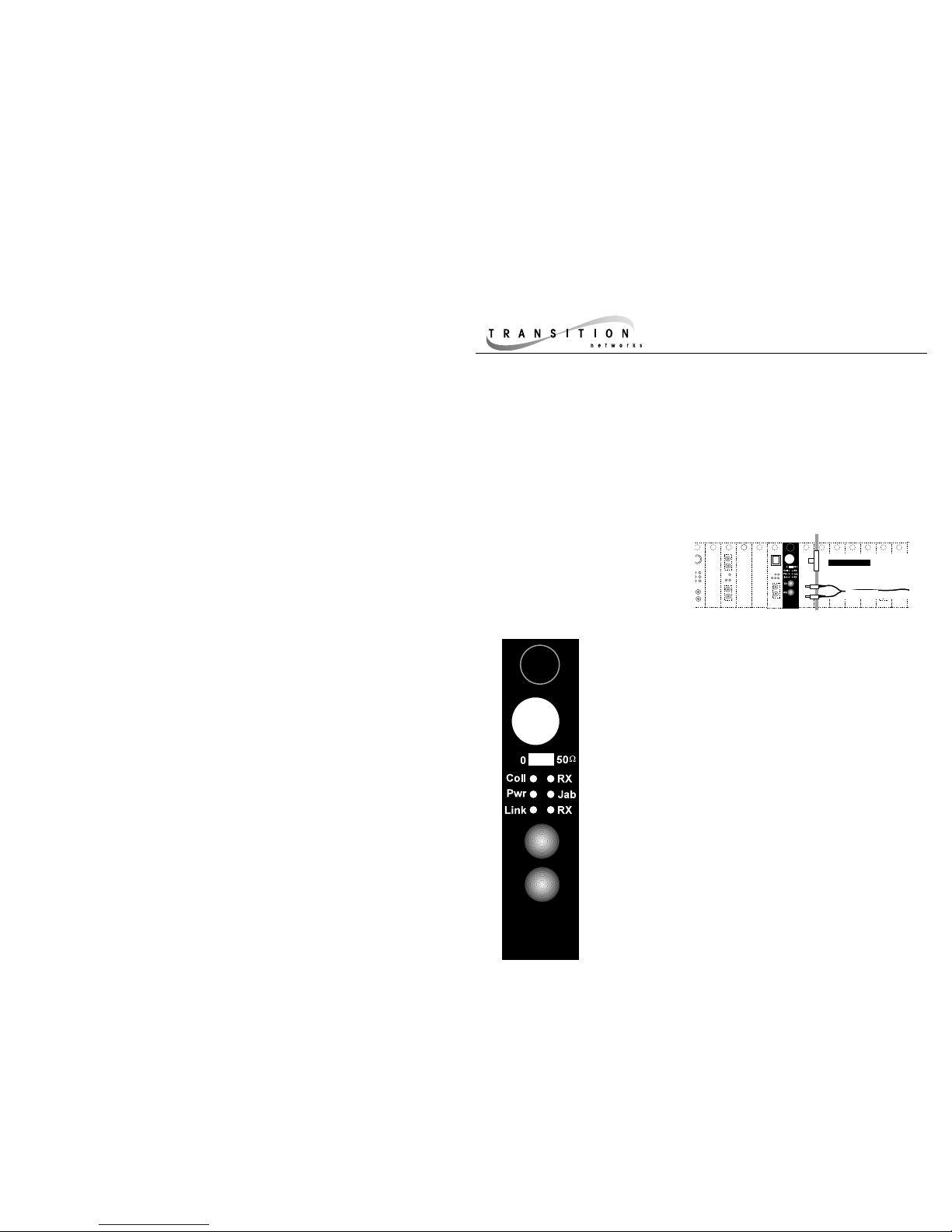
C/E-CX-FRL-04
C/E-CX-FRL-04
Provides a coax connector to 10BASE-2
coaxial “thin-net” Ethernet™ cable and a
set of RX (receive) and TX (transmit) ST
10BASE-FL connectors to 850nm
multimode fiber cable.
A Coax configuration switch sets an internal 10BASE-2 terminator
to EITHER 50 ohms OR 0 ohms.
• 0 ohm switch position is used when connecting to the
middle or in line of a thin coax segment.
• 50 ohm switch positionis used when connecting end of
coax segment DIRECTLY to the media converter's BNC
port.
C/E-CX-FRL-04
10BASE210BASE-FL
Ethernet
TM
TX
RX
Status LEDs
Coax Switch
Page 2

1. Is the power LED on the media converter illuminated?
NO
• Is the Slide-In-Module properly connected to the Media Conversion Center chasis
backplane?
• Is the Power Supply Module properly connected both to the Media Conversion Center
chasis backplane and to the AC outlet?
• Contact Technical Support at (800) 260-1312/ (800) LAN-WANS.
YES
• Proceed to step 2.
2. Is the 10BASE-2 link able to receive signals?
NO
• Check coax cables for proper connection.
• Check coax cable for opens or shorts. Check and/or replace each BNC “T” connector
on the segment, making sure each “T” is attached firmly.
• Verify that coax cables on media converter are terminated properly at both ends.
NOTE: In a coax thinnet installation, the first and last device in a daisy-chain are
terminated.
• Verify that each 10BASE-2 segment is grounded to earth ground.
• Contact Technical Support at (800) 260-1312/ (800) LAN-WANS.
YES
• Proceed to step 3.
3. Is the fiber Link LED illuminated?
NO
• Check fiber cables for proper connection.
• Verify that TX and RX cables on media converter are connected to RX and TX ports,
respectively, on the other 10BASE-FL device.
• Contact Technical Support at (800) 260-1312/ (800) LAN-WANS.
YES
• Contact Technical Support at (800) 260-1312/ (800) LAN-WANS.
Troubleshooting
Installing Slide-In-Module(s)
The physical characteristics of the media cable must meet or exceed IEEE
802.3 10BASE-2 and 10BASE-FL specifications.
ETHERNET CABLE SPECIFICATIONS
10BASE-FL CABLE SPECIFICATIONS
850nm MULTIMODE
Fiber Optic Cable Recommended: 62.5 / 125 µm multimode fiber
Optional: 100 / 140 µm multimode fiber
85 / 125 µm multimode fiber
50 / 125 µm multimode fiber
Fiber Optic Transmitter Power: Average power: -15.0 dBm
Peak power: -12.0 dBm ±1dBm
Fiber Optic Receiver Sensitivity: Average sensitivity: -32.5 dBm
Bit error rate:≤10
-10
Maximum Cable Distance: 2000 meters
CAUTION: Wear a grounding device and observe electrostatic discharge precautions when
installing Media Converter Slide-in-Module(s) in the 16-Slot Media Conversion Center. Failure to
observe this caution could result in damage to, and subsequent failure of, the Media Converter
Slide-in-Module(s).
NOTE: Media Converter Slide-in-Modules can be installed in any installation slot, in any order.
To install the Media Converter Slide-in-Module in the E-MCC-1600 chassis:
1. Remove Media Converter Slide-in-Module protective plate from selected installation slot by
removing two screws that secure plate to front of E-MCC-1600. Retain one installation screw.
2. Carefully slide Media Converter Slide-in-Module into installation slot, aligning Media Converter
Slide-in-Module with installation guides.
NOTE: Ensure that the Media Converter Slide-in-Module is firmly seated against the backplane.
3. Secure Slide-in-Module by installing retained installation screw.
10BASE-2 CABLE SPECIFICATIONS
Cable type: Stranded Coaxial RG58
Impedance: 50 Ω @ 10 MHz
Mutual Capacitance: 24 pF/ft ±20% @ 10 MHz
Maximum Cable Distance: 185 meters (610 feet)
Maximum number connections:30
Minimum distance/connection: 0.5 meters (1.6 feet)
10BASE-2 CABLE CONNECTIONS
• Ground EACH coax segment to earth ground at one end.
• Set coax configuration switch:
Use 50 ohm switch position when connecting the end of a coax segment
DIRECTLY to the media converter's BNC port.
Use 0 ohm switch position when connecting to the middle or in line of a
thin coax segment. (For this position a BNC "T" must be connected to the
media converter's BNC port).
10BASE-FL CABLE CONNECTIONS
• Verify that the fiber products to be connected are 10BASE-FL or FOIRL
compliant. NOTE: Fiber ports on TRANSITION Networks fiber media
converters conform to 10BASE-FL or FOIRL but NOT to 10BaseFB or FDDI.
C/E-CX-FRL-04
 Loading...