

Transition Networks C/E-100BTX-SX-01(SC), C/E-100BTX-SX-01 User Manual
The TRANSITION Networks C/E-100BTX-SX-01 series of 100BASE-TX to 100BASE-SX
slide-in-module media converters, designed to be installed in the TRANSITION
Networks Media Conversion Center, E-MCC-1600, connect 100BASE-TX unshielded
twisted pair cable to 850 nm multimode fiber-optic cable.
A four-positiion switch allows selection of Auto-negotiation, half-duplex or full-duplex,
and/or Link Pass Through (LPT) /Remote Fault Detection (RFD). An MDI/MDI-X switch
allows straight-through twisted-pair cable to be used for crossover 100BASE-TX
connections.
Minneapolis, MN 55344 USA
CAUTION: RJ connectors are NOT INTENDED FOR CONNECTION TO THE
PUBLIC TELEPHONE NETWORK. Failure to observe this caution could result in
damage to the public telephone network.
Compliance Information
UL Listed
C-UL Listed (Canada)
CISPR/EN55022 Class A
FCC Regulations
This equipment has been tested and found to comply with the limits for a class A digital device, pursuant
to part 15 of the FCC rules. These limits are designed to provide reasonable protection against harmful
interference when the equipment is operated in a commercial environment. This equipment generates,
uses, and can radiate radio frequency energy and, if not installed and used in accordance with the
instruction manual, may cause harmful interference to radio communications. Operation of this
equipment in a residential area is likely to cause harmful interference, in which case the user will be
required to correct the interference at the user’s own expense.
Canadian Regulations
This digital apparatus does not exceed the Class A limits for radio noise for digital apparatus set out on
the radio interference regulations of the Canadian Department of Communications.
Copyright Restrictions
© 1998-1999. 2001TRANSITION Networks.
All rights reserved. No part of this work may be reproduced or used in any form or by any means –
graphic, electronic, or mechanical – without written permission from TRANSITION Networks.
Trademark Notice
All registered trademarks and trademarks are the property of their respective owners. 33065.C
Der Anschluss dieses Gerätes an ein öffentlickes Telekommunikationsnetz in den EG-Mitgliedstaaten
verstösst gegen die jeweligen einzelstaatlichen Gesetze zur Anwendung der Richtlinie 91/263/EWG zur
Angleichung der Rechtsvorschriften der Mitgliedstaaten über Telekommunikationsendeinrichtungen
einschliesslich der gegenseitigen Anerkennung ihrer Konformität.
MEDIA CONVERTER TECHNICAL SPECIFICATIONS
Standards 100BASE-SX, IEEE 802.3u
Environment Temperature: 0-40°C (32° to 100°F )
Humidity 10-90%, non condensing
Altitude 0-10,000 feet
Warranty Lifetime
100BASE-TX/100BASE-SX 850 Nanometer
Slide-In-Module Media Converters
C/E-100BTX-SX-01, C/E-100BTX-SX-01(SC)
USER’S GUIDE
850nm 100BASE-S
X
Multimode
Fiber
100BASE-TX
Copper
C/E-100BTX-FRL
-03
P
100BASE-FX 100BASE-TX
Fast Ethernet
TM
C/100BTX-SX-04
850nm 100BASE-SX
Multimode
Fiber
100BASE-TX
Copper
C/E-100BTX-FRL
-03
P
100BASE-FX 100BASE-TX
Fast Ethernet
TM
C/100BTX-SX-04(SC)
C/E-100BTX-SX-01
Provides an RJ-45 twisted pair 100BASETX connector and a set of RX (receive)
and TX (transmit) ST 100BASE-SX
connectors to multimode fiber-optic
cable.
C/E-100BTX-SX-01(SC)
Provides an RJ-45 twisted pair 100BASETX connector and an RX (receive) and
TX (transmit) SC 100BASE-SX connector
to multimode fiber-optic cable.
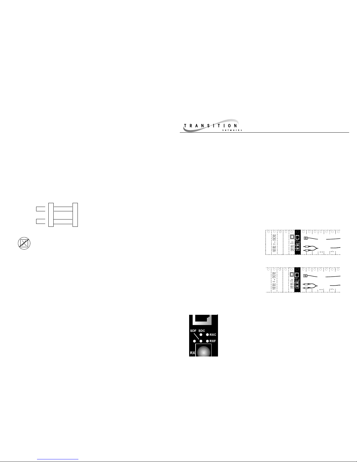
Power Illuminated green LED indicates connection to external
AC power.
SDF Signal Detect/Fiber: Steady green LED indicates fiber port
is connected to device.
SDC Signal Detect/Copper: Steady green LED indicates RJ-45
port is connected to device.
RXC Receive/Copper: Flashing green LED indicates packets
are seen on RJ-45 port.
RXF Receive/Fiber: Flashing green LED indicates packets are
seen on fiber port.
P
-FX 100B
A
Status LEDs
Straight-through Cable Configuration
Straight-through/crossover 100BASE-TX requirements are satisfied using the
MDI/MDI-X switch with straight-through cable.
The two active pairs in a 100BASE-TX
network are pins 1 & 2 and pins 3 & 6.
Use only dedicated wire pairs (such as
blue/white & white/blue, orange/white &
white/orange) for the active pins.
1
2
3
6
Twisted
Pair #1
Twisted
Pair #2
Straight Through Cable
1
2
3
6
1. Is the power LED on the media converter illuminated?
NO
• Is the Slide-In-Module properly connected to the Media Conversion Center
chasis backplane?
• Is the Power Supply Module properly connected both to the Media
Conversion Center chasis backplane and to the AC outlet?
• Contact Technical Support at (800) 260-1312/ (800) LAN-WANS.
YES
• Proceed to step 2.
2. Is the 100BASE-TX SDC LED illuminated?
NO
• Check UTP cables for proper connection and pin assignment. (See above.)
• Contact Technical Support at (800) 260-1312/ (800) LAN-WANS.
YES
• Proceed to step 3.
3. Is the fiber SDF LED illuminated?
NO
• Check fiber cables for proper connection.
• Verify that TX and RX cables on media converter are connected to RX and
TX ports, respectively, on the other 100BASE-SX device.
• Refer to Tech Tips available at: http://www.transition.com
• Contact Technical Support at (800) 260-1312/ (800) LAN-WANS.
YES
Troubleshooting
The physical characteristics of the media cable must meet or exceed IEEE
802.3u 100BASE-TX and 100BASE-SX specifications.
Ethernet Cable Specifications
100BASE-SX Cable Specifications
MULTIMODE
Fiber-optic Cable Recommended: 62.5 / 125 µm multimode fiber
Optional: 50 / 125 µm multimode fiber
Modal bandwidth: ≤160MHz-Km
Fiber-optic Transmitter Power: min: -20 dBm max: -12 dBm
Fiber-optic Receiver Sensitivity: min: -24 dBm max: -12 dBm
Wavelength: 850nM
Bit error rate: ≤2.5
-10
Maximum Cable Distance: 2-300 meters
100BASE-TX Cable Specifications
Category 5 wire or better is required. Either shielded twisted pair
(STP) or unshielded twisted pair (UTP) can be used. Use a straightthrough cable configuration (see back page).
Category 5:
Gauge 24 to 22 AWG
Attenuation 20 dB/1000’ @ 10 MHz
Impedance 100 Ω ±10% @ 10 MHz
Maximum Cable Distance: 100 meters (330 feet)
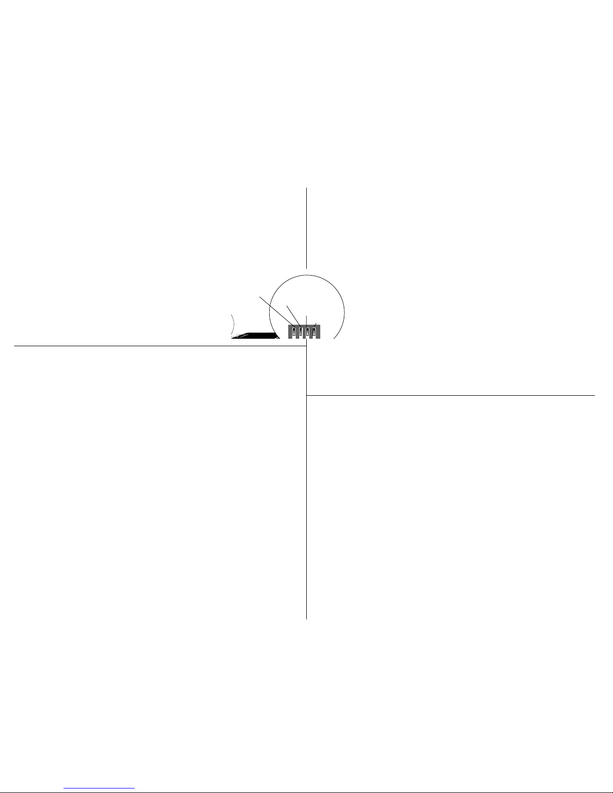
Installing Slide-In-Module(s)
CAUTION: Wear a grounding device and observe electrostatic discharge precautions
when installing Media Converter Slide-in-Module(s) in the 16-Slot Media Conversion
Center. Failure to observe this caution could result in damage to, and subsequent
failure of, the Media Converter Slide-in-Module(s).
NOTE: Slide-in-Modules can be installed in any installation
slot, in any order.
To install the Media Converter Slide-in-Module in the E-MCC1600 chassis:
1. Ensure that switches on circuit board are set correctly for
site installation.
2. Remove Media Converter Slide-in-Module protective plate
from selected installation slot by removing two screws that secure
plate to front of E-MCC-1600. Retain one installation screw.
3. Carefully slide Media Converter Slide-in-Module into installation slot, aligning
Media Converter Slide-in-Module with installation guides.NOTE: Ensure that the
Media Converter Slide-in-Module is firmly seated against the backplane.
4. Secure Slide-in-Module by installing retained installation screw.
C/E-100BTX-SX-01
4-Position Switch (4th switch not used)
Auto-negotiation (UP) Detects and adapts to line
speed/operation mode of attached device.
Full/Half-duplex (UP) Allows an attached full-duplex station to
transmit and receive simultaneously. (DOWN) Allows an
attached station to transmit and receive sequentially.
LPT/RFD (UP) Blinks the SDF or SDC LED if a malfunction is
detected at the unit to which the media converter is attached.
Use small flatblade screwdriver or similar device to set recessed switches. Refer to label on top of
media converter for MDI/ MDI-X switch settings. Refer to drawing for four-position switch settings.
MDI/MDI-X Straight-Through/Crossover Straight-through/crossover 100BASE-TX requirements are
satisfied using the MDI/MDI-Xswitch with straight-through cable. Set the MDI/MDI-X switch to MDI for
cable connections between hub and media converter. Set the MDI/MDI-X switch to MDI-X for cable
connections between media converter and terminal, transceiver or NIC.
Switch Settings and Cable Requirements
E
9
V
LPT/RFD UP=ON
Auto-negotiation UP=ON
Full/Half-duplex UP=FULL
(not used)
DI
sition
 Loading...