


TransitHound
Cellphone Detector
User Manual Version 1.3
RF3
RF2

Table of Contents
Introduction.............................................................3
PC Requirements......................................................3
Unit Description.......................................................3
Electrical Interfaces..................................................4
Interface Cable..........................................................5
USB to Serial Interface Cable (optional)..................6
Software.....................................................................7
Overall Specifications................................................10
Reference Drawings (cables).....................................11
Reference Drawings(cables)......................................12
Antenna Information...............................................13
Antenna Information...............................................14

INTRODUCTION
The purpose of this document is to help the user set up the TransitHound Cellphone
Detector (THCD) unit and associated graphic user interface software (TransitHound
Controller-Serial) To set up the system, the user needs the following components:
1. PC/Laptop/Notebook host running Windows (7) (provided by
customer)
2. THCD unit
3. Serial Interface cable (Hirose 6 pin (round) to open leads) (provided by
BVS)
4. TransitHound Controller-Serial software package (provided by
BVS)
Components 1 through 4 are further discussed below:
PC/Laptop/Notebook running Windows (7)
The PC/Laptop/Notebook hardware platform needs to meet the following minimal
requirements:
Windows OS (7)
512 MB RAM
20GB storage space
800 MHz processor speed
3 of 14

Unit Description
The THCD unit comes with a monopole omni-directional antenna covering the above
frequency bands. This compact antenna is well-suited for deployment in cramped spaces
with multiple reflecting boundaries and/or metal surfaces.
Electrical Interfaces
The THCD unit has the following electrical interfaces:
1. Ground (un-insulated terminal)
2. RS232 Serial port (6-pin Hirose round connector)
Ground and Hirose connector side of Transithound
4 of 14
3. RF input port with SMA connector used for omni-directional antenna
or connect to a cable delivering RF signal from a non co-located antenna.
RF Input port on Transithound
The THCD unit is enclosed in a specially designed metal box consisting of a tubular
body, two end covers and two conducting gaskets constituting an external EMI shield.
The unit also has an inner secondary shield enclosing the RF receiver stages for extra
attenuation of disproportionately strong ambient electromagnetic fields.
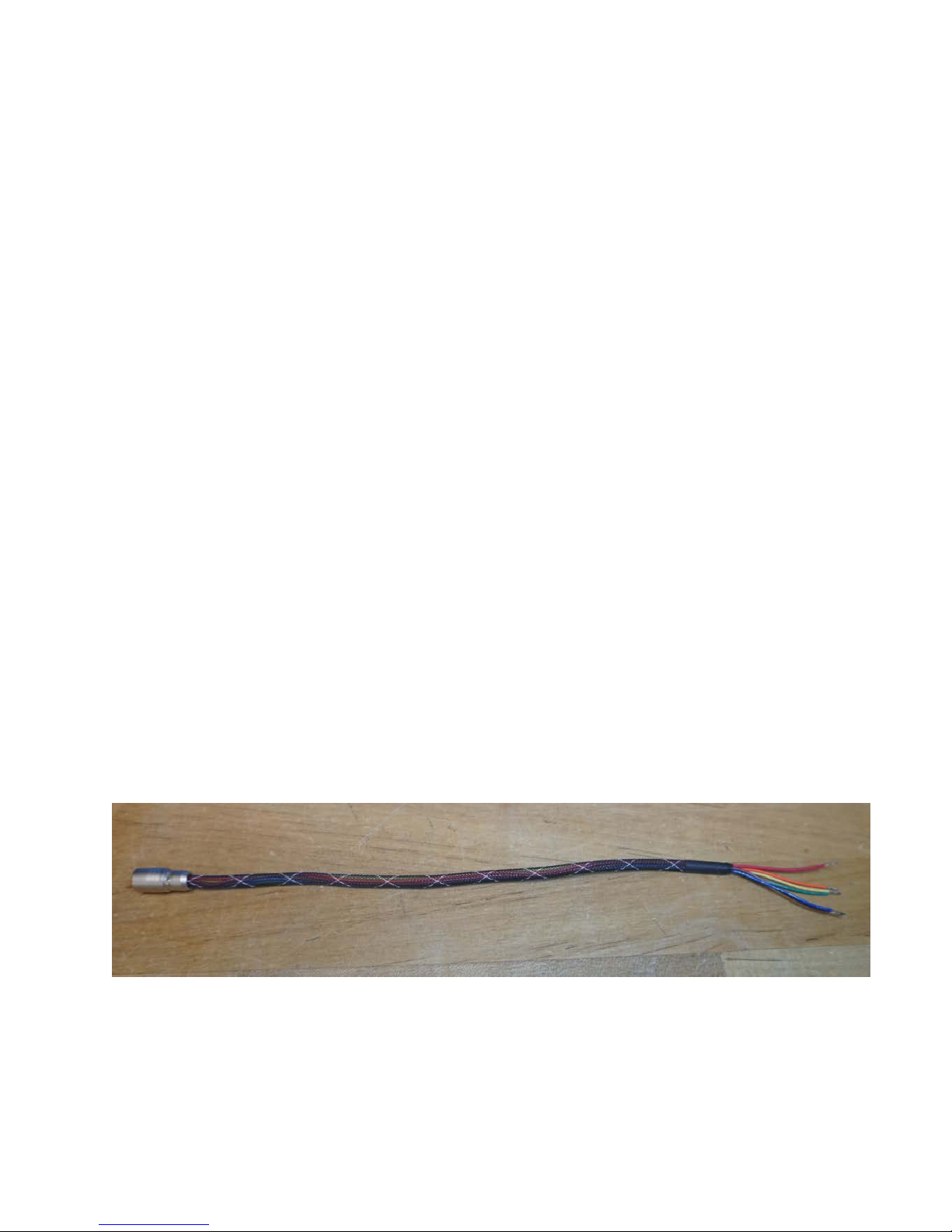
Transithound Interface Cable
This cable can be used to interface between the Transithound and your computer.
Additional modification to the cable is required by the customer. See page 10 for
drawing.
5 of 14

USB to Serial Interface Cable (Optional)
The THCD unit is controlled by the PC over a Serial port, via the USB to Serial Interface
Cable provided by BVS. This cable is terminated by USB, Hirose 6-pin round type
connector, dry contacts and input for a power supply at its ends. The Hirose 6-pin round
end of the cable connects to the RS232 serial port of the THCD unit. The USB end of the
cable fits on the corresponding USB port of the PC. See page 10 for drawing.
Typical lab set up of the Transithound connected to a computer via the USB
to Serial Interface Cable Note: External power supply is needed to power the
unit via the interface cable.
6 of 14

TransitHound Controller-Serial User Interface Software Installation
The driver for the THCD unit and the graphic user interface program for using the
system are installed by initiating the TransitHound Controller-Serial program on the
BVS-supplied USB Stick. The installation is relatively straightforward; it starts by
running setup and following menu instructions.
Installing the Software
Run the TransitHound Controller-Serial program, the following user graphic interface screen
will appear (Figure 3):
Figure 3. Graphic User Interface screen
Click “Open” from Figure 3; then select a listed port in Figure 4, then click “OK”:
Figure 4. Selecting the Com Port
7 of 14

Following the COM port selection, the monitoring screen will display the detected signal
in real-time on the graph at right hand side, as seen in Figure 5:
The firmware and serial number fields also fill in automatically when the COM Port is selected.
( Note the firmware version of your Tranisthound may not match the firmware version from the
screen shot below.)
Figure 5. Monitoring Screen Displaying Real-Time Data
Transit Hound Functional parameters configurable by the user.
1. Threshold – Auto or Manual threshold set by the user determines the signal strength
level used to trigger the internal solid-state relay (SSR). The dry contact of this relay is
connected to the 6-pin Hirose connector and is being used to trigger an external Alarm in
some applications. In the Manual threshold mode, SSR is triggered, when RF signal
exceeds the set threshold. In the Auto threshold mode the user set “Auto Trigger Margin”
determines by how much the current threshold must be exceeded in order to trigger the
SSR.
Transit Hound Auto threshold algorithm:
All uplink cellular frequencies are scanned with a 4 MHz or 20MHz resolution. Signal
strength is sorted along the scan. The maximum value is a “sample”. This process is
continuous and periodic; each period takes approximately 0.6 sec for the US set of
frequencies.
As long as the “new sample” is lower than the current threshold, the latter is calculated as
a moving average of 16 samples increased by the auto threshold margin. It takes up to 16
* 0.6 = 10 sec for the auto threshold to settle after the input signal change.
If the input signal exceeds the current threshold, the threshold stays unchanged for the
next 20 sec. After delay the threshold and each of the 16 entries of the circular buffer are
set to the maximum level of 1000, thus forcing the algorithm to perform step 2., starting
with the next sample.
8 of 14

2. RF Attenuation – even values from 0 to 30 dB can be set to reduce the input level of
RF as seen by the Transit Hound. This feature can be used to contain the detection
radius, for instance, to limit detection around the operator’s compartment in a moving
vehicle. Another reason to use attenuation is in presence of a strong out of band RF
interference that otherwise could saturate the receiver’s front end and compromise the
cell phone detection.
3. Rising Trigger Delay is essentially a filter that allows the customer to set how long the
duration of a signal above the threshold has to be before SSR is triggered. Values are in
scan cycle periods. For instance, the signal must exceed the threshold and stay above it
for three complete cycles before triggering the SSR, if the rising trigger delay is set to 3.
This parameter can be set, for instance, to ignore pings of an idling phone to the tower.
4. Falling Trigger Delay is a different filter – one that allows the customer to set how
long the pause in the signal has to be before the SSR trigger is reset. Units are also in
scan cycles. This parameter allows to greatly reduce the amount of entries in a log file – a
long phone conversation will be logged as one event versus multiple entries every time
the signal gets interrupted and then again re-assigned.
5. Band – list of implemented band selections is being read from the Transit Hound.
When the user selects the country, the scan is limited to the appropriate custom set of
uplink cellular frequencies.
9 of 14

Overall Specifications
Cell Phone Detector Unit
Sensitivity -80 dBm
Dynamic Range 60dB
Resolution Bandwidth 4MHz/RF2 ; 4 & 20 MHz/RF3
Selectivity 50dB at 1MHz from band edge
Electrical Interfaces
Hirose (Serial RS232 Port, dry contact)
Antenna Port (coaxial/SMA)
Ground
Receive Antenna
Omni-directional
PC/Laptop/Notebook Platform
Windows 7
512MB RAM
20GB storage space
800 MHz processor speed
10 of 14

Cable Drawings
11 of 14

Cable Drawings
12 of 14

Transithound Antennas
Omni Directional Multi Band Antenna
13 of 14

BVS patch antenna enclosure with 15’ cable with M17/60-RG-142/U
Pentaband Cellular PCB Antenna
 Loading...