

Page 1

0
15,0,15,0,1,14,1,14,13,2,13,2,3,12,3,12,11,4,11,4,5,10,5,10,9,6,9,6,7,8,7,8
Operation Manual
Professional Benchtop
pH meter
BP3001
Page 2

1
INTRODUCTION
Your purchase of this professional bench-top pH meter marks a step
forward for you into the field of precision measurement. Although this
meter is a complex and delicate instrument; its usability will allow many
years of use if proper operating techniques are observed and practiced.
Please read the following instructions carefully and always keep this
manual within easy reach.
1. FEATURES:
• Multiple display of pH, temperature simultaneously
• Automatic buffer recognition with built in ISO and NIST standard
• Manual setting of customize buffer standard
• 5 points calibration
• Hold or freeze display function
• 99 memory with real time clock recording
• Maximum and minimum data review
• RS232 online data logging to PC
2. CONTENT:
Carefully unpack the box. It should contain the following items:
a. Main unit
b. Combination pH electrode with built-in temperature sensor
c. Electrode stand
d. AC – DC adaptor (Non-universal, for local power point use only)
e. RS232 PC communication kit
f. Operations manual
Page 3
2
3. SPECIFICATION:
Range
0 to 14 pH
±1999mV 0 to 90ºC
Resolution
0.01pH
0.1mV ~199.9
1mV ~1999
0.1ºC
Accuracy
±0.02pH
±0.2mV ~199.9
±2mV ~1999
±0.5ºC
Calibration
5 point selectable
Operating voltage
9 to 12VDC, min. 650mA
Operating temperature
5 to 40ºC
Storage temperature
-20 to 60ºC
Operating humidity
Up to 95% RH
Meter size
217 x 168 x 58mm
Package size
Package weight
2.1kg
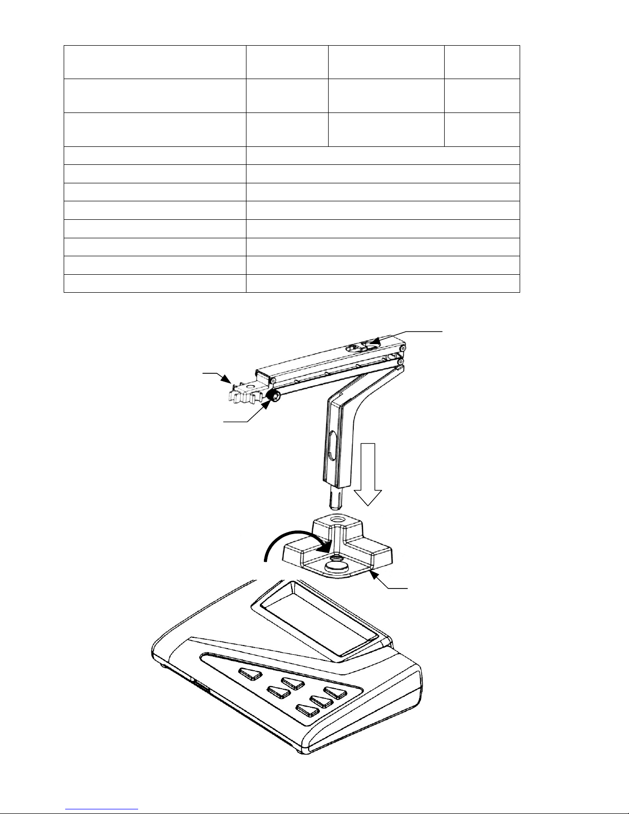
4. PRODUCT ASSEMBLY:
Turn anti-clockwise to
loosen arm to adjust angle,
turn clockwise to lock arm
into position
Place meter’s left corner onto the
STAND-BASE to set into position.
Electrode stand can be set on the
right corner of meter as desired
Complete the stand-assembly by
pushing the arm into the top hole
of the STAND-BASE fully to lock
Electrodes holder
Cable holder
STAND-BASE
Page 4
3
5. ELECTRODE & SENSORS
The pH electrode is one of the important sensing elements in the pH
measuring system. Understanding and maintaining the electrode in
good conditions will ensure consistent and accurate measurement all
the time.
5.1 The supplied pH electrode is a plastic body combination sealed
general-purpose electrode with build in temperature sensor.
5.2 There are specialized electrodes for different purpose and for
measuring different liquid. This general-purpose electrode should
only be used to measure city water. It is not made for measuring
ultra-pure water, high viscosity liquid, cream, oil or solvent based
liquid. Specialized electrode can be purchased separately for
your specific needs.
5.3 The pH electrode is an electro-chemistry sensor
that contains special chemicals and a pH sensitive
glass bulb. The glass bulb is half of the measuring
element and must be kept wet to enhance speed of
measurement. If the sensor is dried out, it will take
a longer time to get hydrated. The other measuring
element is the reference element, which contain
concentrated chemical with a liquid bridge of porous
fiber, allowing controlled contact with the measuring
liquid. In order to keep both sensors in ideal
condition; the electrode is constantly soaked in a
specially formulated liquid concentrate.
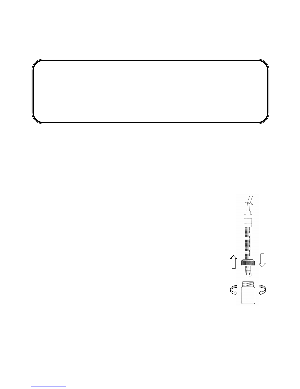
5.4 Before using the electrode,
unscrew the soaker bottle then
_
remove the cap. Rinse the sensor area with distilled water
several times before proceeding with testing.
5.5 After using the electrode, first put back
the cap then
screw
the bottle into place tightly to prevent leakage.
PRECAUTION ON USE
!
Do not touch or scratch the pH glass sensor. It is fragile and delicate.
Do not clean sensor with alcohol.
Never use distilled water for storage.
Store the electrode in the storage solution.
Always rinse the electrode with distilled water before and after each test.
Page 5
4
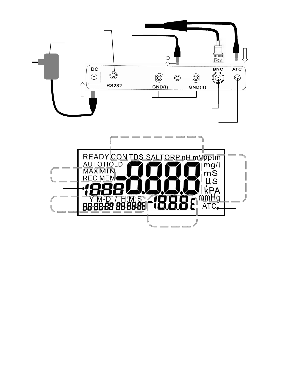
6. BACK PANEL CONNECTION:
7. DISPLAY PANEL:
1 – Measurement functions indicator
2 – Units of measurement
3 – Indicates reading with automatic temperature compensation
4 – Sub-display for Temperature display or program number in
SETUP mode or buffer standard in CALIBRATION mode.
5 – Real time clock in “Year-Month-Date / Hour : Minute : Second”
6 – Memory data counter and CALIBRATION mode indicator
7 – Memory recall / review indicator:
MEM – Flash momentarily while data is being saved
MAX – Maximum reading of all saved data displayed
MIN – Minimum reading of all saved data displayed
REC – Flashing while recall mode is initiated
HOLD – Display put on hold
READY – When the READY feature is enabled, during measurement it will
flash, indicating measurement in progress. When stopped,
indicates reading has stabilized.
7
5
4
2
1
6
3
Socket for RS232 cable
for PC data transfer
AC-DC Adaptor
(Non-universal,
connect to your local
power point only)
Socket for earth
grounding
BNC socket for
pH/ORP electrode
Socket for temperature probe
Socket for
Analog Output
Analog Recorder output
using sub-
miniature 2.5mm
phone jack (not supplied)
-
Page 6
5
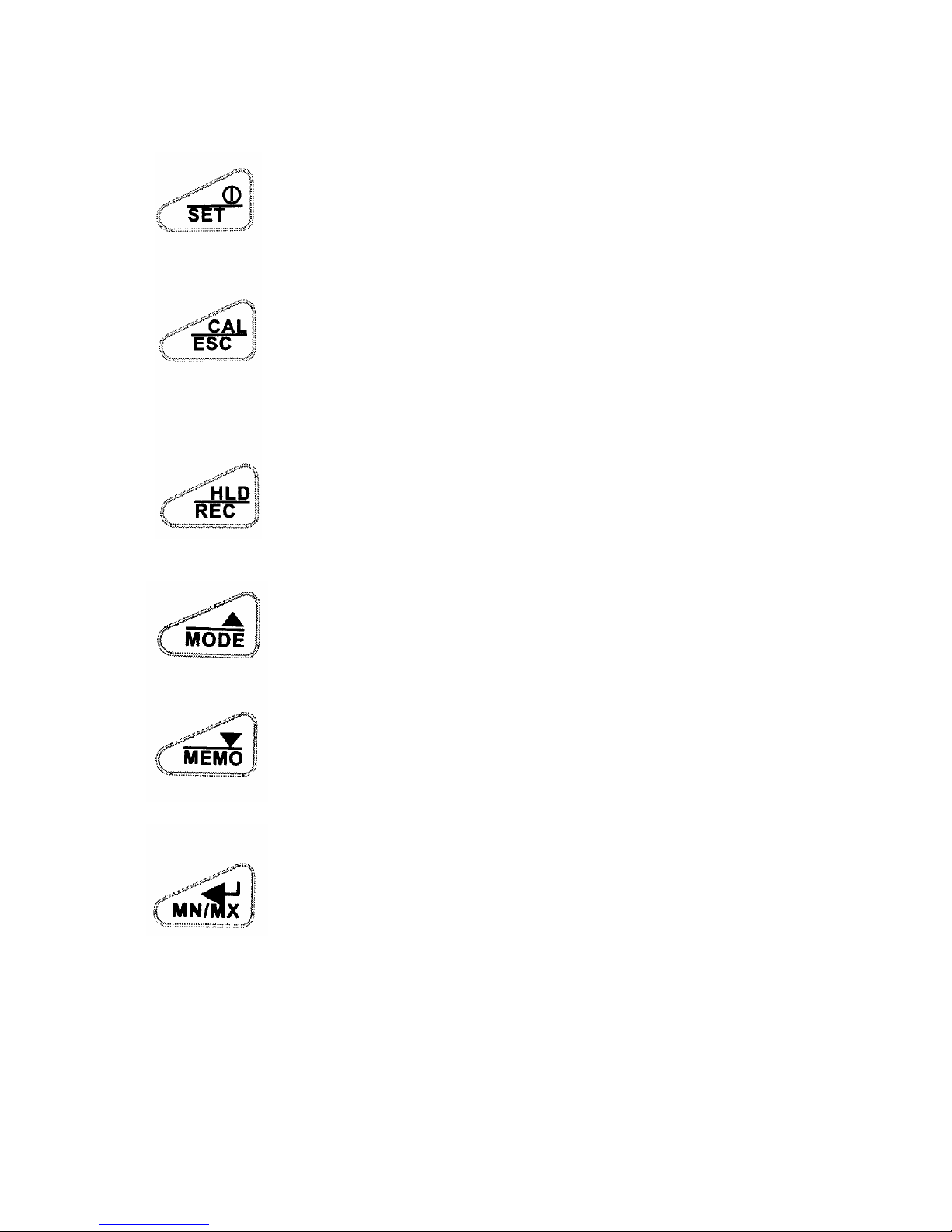
8. KEY PAD PANEL
Get familiarized with the key buttons will help you to operate the meter
with ease.
ON-OFF & SETUP KEY
1. Press to switch ON or OFF the meter
2. Press and hold down to enter SETUP mode
CALIBRATION & EXIT KEY
1. Press to enter CALIBRATION mode
2. During SETUP or RECALL mode, press to EXIT
HOLD KEY & RECALL KEY
1. Press to freeze or put display on hold. Press again to
release.
2. Press and hold down to enter RECALL mode
MODE KEY & MOVE-UP/SELECT KEY
1. Press to switch display mode between pH and mV
2. During setting, press to move digit up or next selection
MEMORY SAVE KEY & MOVE-DOWN / SELECT KEY
1. Press to save current reading into memory
2. During setting, press to move digit down or previous
selection
CONFIRM KEY, MAXIMUM / MINIMUM DISPLAY KEY
& TEMPERATURE SET KEY
1. During CALIBRATION or SETUP setting, press to
confirm setting.
2. While in RECALL mode, press to display maximum
and again for minimum reading of all saved data.
3. When making measurement without temperature
mode, press and hold down to enter temperature
adjustment mode.
Page 7
6
9. SETTING UP THE UNIT:
9.1 Before you begin using the unit, it is important to define your measuring
requirements. These will allow the unit to display accurately on the
condition of sample that is being measured.
9.2 After the unit is switched ON, press and hold down the key until
display shows tr
trtr
tr.
9.3 Press to go to next parameter and for previous parameter.
Below are the description of each parameter setting:
(Anytime during setup, press to cancel or return to measuring mode)
tr
(P1
P1P1
P1.0000) DATA TRANSMISSION TO PERSONAL COMPUTER
This setting allows you to download saved memory data to PC via the
RS232 connection.
1. Download a free software from the internet at the below link:
http://www.eltima.com/download/rs232-data-logger
2. Connect the RS232 cable to the back of the meter and PC RS232
socket. Optional USB interface connector can be used.
3. Install and RUN the application on the PC.
4. Under Available ports, select the com port meter is connected to.
5. Click to select file location and type file name then click save.
6. Set Baud-rate to 9600, Data-bits to 8, Parity to non, Stop-bits to 1,
Flow control to non and Click
7. Press on the meter and display will show
out
outout
out
(P1
P1P1
P1.1111)
flashing, PC will indicate transmission in progress.
8. When transmission is completed, display will return to tr P1
tr P1tr P1
tr P1.0000.
9. On the PC, click and a text file will be created.
10. Locate the directory and open the file in text format. Data is
display with time and date for analysis.
11. Press to go to next parameter.
Clr
(P2
P2P2
P2.0000) CLEAR MEMORY
This setting will clear all the saved memory in the unit.
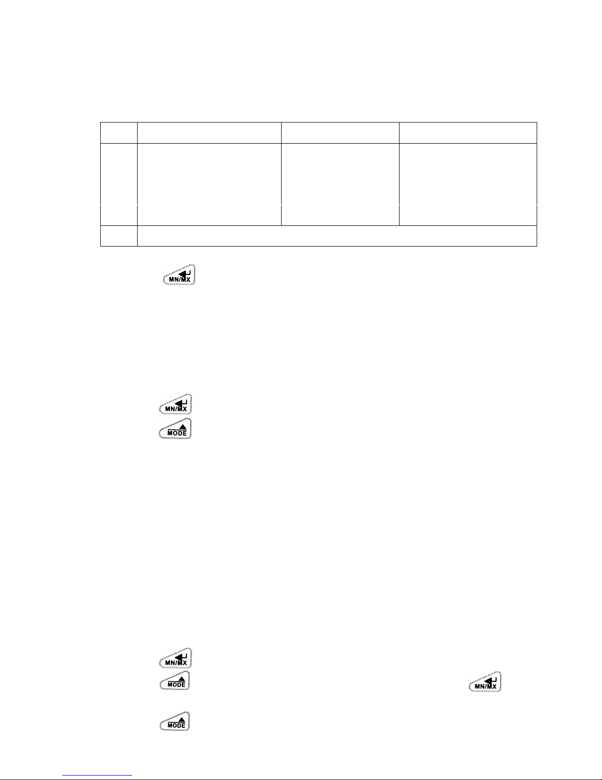
1. Press and display will show nnnno
o o
o (P2
P2P2
P2.1111) flashing.
2. Press once to select between YES
YESYES
YES or no
nono
no. If you select YES
YESYES
YES
and press , all memory will be cleared. Otherwise select no
nono
no
then press , display will return to CLr
CLrCLr
CLr (P2
P2P2
P2.0000).
3. Press to go to next parameter.
. . .
Start logging
Stop logging
Page 8
7
Ele
(P3
P3P3
P3.0000) REVIEW OF ELECTRODE STATUS
This setting allows you to review the last calibration information about
the electrode conditions.
1. There are 5 calibration points for review in the follow order:
SAVED DATA NIST Buffer range
ISO/ Custom Buffer range
P3.1
% of Calibration slope 0.00 to 4.01 0.00 to 4.50
P3.2
% of Calibration slope 4.02 to 6.86 4.51 to 7.00
P3.3
% of Calibration slope 6.87 to 9.18 7.01 to 9.50
P3.4
% of Calibration slope 9.18 to 14.00 9.51 to 14.00
P3.5
Calibration offset value in mili-volt (mV)
2. Press and display will show value in percentage (%) for
P3
P3P3
P3.1111. Repeat for the next value, in the above table order.
3. A good electrode should have a value of above 75% and below
115%. Otherwise, the electrode should be replaced.
4. At P3.5, display will show the calibrated offset value in mV. A good
electrode should have a value not greater than ±60mV. Otherwise,
the electrode should be replaced.
5. Press to return to ELE
ELEELE
ELE (P3
P3P3
P3.0000)
6. Press to go to next parameter.
Buf
(P4
P4P4
P4.0000) BUFFER CALIBRATION STANDARD
This setting allows you to select ISO, NIST or customized buffer
standard. Factory preset is ISO standard.
ISO (iiiiSo
SoSo
So) buffer standards are pH1.68, 7.00, 4.01, 10.01, 12.45 and
NIST (nnnniiiiSt
StSt
St) buffer standards are pH1.68, 4.01, 6.86, 9.18 and 12.45,
which are preset in this meter, and will be automatically recognized
during calibration.
Select customize (CUSt
CUStCUSt
CUSt) if you have other standards other than Nist
buffer solutions. This will allow you to set each calibration point to the
standard buffer solution available, which are about to calibrate.
1. Press and display will show CUSt
CUStCUSt
CUSt (P4
P4P4
P4.1111) flashing.
2. Press once to select IIIISO
SOSO
SO, n
n n
niiiiSt
StSt
St or CUSt
CUStCUSt
CUSt. Press and
display will return to BuF
BuFBuF
BuF (P4
P4P4
P4.0000).
3. Press to go to next parameter.
Page 9

8
Rdy
(P6
P6P6
P6.0000) STABILITY INDICATOR
This setting allows you to switch ON or OFF the stabilized reading
indicator. Whenever the READY sign appear on the top left corner of
the display, it indicates that a stable reading has reached. This will be
helpful to eliminate guesswork. In some case, especially where the
reading is very slow in response, switch OFF the indicator for
independent user’s judgment. Factory preset is ON.
1. Press and display will show yES
yESyES
yES (P6
P6P6
P6.1) with flashing.
2. Press to select between yES
yESyES
yES or no
nono
no
3. Set to no
nono
no and press to disable endpoint indicator, display
will return to Rdy
RdyRdy
Rdy (P6
P6P6
P6.0000)
4. Press to go to next parameter.
Un it
(P7
P7P7
P7.0000) UNIT OF MEASUREMENT
This setting allows you to set the unit of measurement for temperature.
Factory preset is in °C.
1. Press and display will show Unit
UnitUnit
Unit (P7
P7P7
P7.1111) with CCCC flashing.
2. Press to change between FFFFor CCCC.
3. Press to confirm setting, display will return to Unit
UnitUnit
Unit (P7
P7P7
P7.0000).
4. Press to go to next parameter.
Rtc
(P8
P8P8
P8.0000) REAL TIME CLOCK
This setting allow you to change the date in Year-Month-Date and time
in Hour:Minute:Second on the unit.
1. Press and display will show rtc
rtcrtc
rtc (P8
P8P8
P8.1111) with 2 digit flashing
below Y-year.
2. Press or to change the value of Year.
3. Press to confirm, display will show rtc
rtcrtc
rtc (P8
P8P8
P8.2222) with the next
2-digit flashing below M-month.
4. Repeat step 2 to 3 to change each setting in the following sequence
of Day(P8
P8P8
P8.3333), Hour(P8
P8P8
P8.4444), Minute(P8
P8P8
P8.5555) and Second(P8
P8P8
P8.6666).
5. After confirming the last setting, display will return to rtc
rtcrtc
rtc (P8
P8P8
P8.0000)
6. Press to go to next parameter.
Page 10
9
RST
(P9
P9P9
P9.0000) MASTER RESET
This setting allows you to reset the unit to the original factory’s default.
Original factory default: buf
bufbuf
buf (P4
P4P4
P4.0000) = iiiiSo
SoSo
So rdY
rdYrdY
rdY (P6
P6P6
P6.0000) = yes
yesyes
yes
1. Press and display will show no
nono
no (P9
P9P9
P9.1111) flashing.
2. Press to select between YES
YESYES
YES or no
nono
no. If you select YES
YESYES
YES and
press , all setting will be cleared and reset to original factory
default. Otherwise select no then press and display will
return to rSt
rStrSt
rSt (P9
P9P9
P9.0000).
3. Press to return to beginning.
9.4 After completing setup, press to exit SETUP.
10. CALIBRATION:
10.1 Prepare standard solutions of at least 2 calibration points. If
measurements are to be made in the acidic range, select 2 points
between pH0 to 7. If measurements are made in the alkaline range,
then select between pH7 to 14. If full range is required, calibrate at
least 3 to 5 calibration points between pH0 to 14.
10.2 Buffer standard must be set during SETUP in page 7, BuF
BuFBuF
BuF (P4
P4P4
P4.0000).
10.3 Standard solutions are in 3 groups of standards – ISO, Nist and
custom standards.
ISO buffer standards are pH7.00, 4.01 and 10.01
NIST buffer standards are pH1.68, 4.01, 6.86, 9.18 and 12.45
Custom standards can be defined by manually set the buffer standard.
10.4 Do keep in mind that buffer standards are specified at 25°C.
Calibration value should set to the exact value as the buffer solution
value correlate to the current calibration temperature.
* Calibration should be performed as
frequently as possible
to ensure accurate measurement, depending on the
frequency of tests performed. Additional calibration
solution should be purchased for future needs.
Page 11
10
Calibration with ISO Standard
10.5 Make sure the unit is properly installed and electrode connected.
10.6 Press and display will show CAL
CALCAL
CAL flashing on the left,
indicating it is in calibration mode.
10.7 This meter has an internal setting of automatic buffer recognition on
the ISO Standard. Always begin with “Offset” calibration first.
10.8 Rinse the pH electrodes in distilled water then dip in the buffer
solution. First Offset buffer (pH7.00) then subsequently slope buffer.
10.9 Main display will show the current measured value and the bottom
sub-display will show the buffer value. Value will vary according to
temperature listed below table:
ISO standard buffer solution Temperature
(°C)
Slope
1.68
Offset
7.00
Slope
4.01
Slope
10.01
Slope
12.45
0 1.67 7.11 4.00 10.32 13.43
5 1.67 7.08 4.00 10.25 13.21
10 1.67 7.06 4.00 10.18 13.00
15 1.67 7.03 4.00 10.12 12.81
20 1.68 7.01 4.00 10.06 12.63
25 1.68 7.00 4.01 10.01 12.45
30 1.69 6.98 4.02 9.97 12.29
35 1.69 6.98 4.02 9.93 12.13
40 1.70 6.97 4.03 9.89 11.99
45 1.70 6.97 4.04 9.86 11.84
50 1.71 6.97 4.06 9.83 11.70
10.10 If the sub-display does not automatically recognize a buffer, it means
the electrode could be defective or the buffer solution is wrong.
Calibration cannot proceed until they are rectified.
10.11 When the READY sign appear on the top left corner, it means you are
ready to confirm the setting. Wait another 10 seconds, if the reading
is not stable, READY sign will disappear. Wait again till it appears.
10.12 Press to to confirm and display will flash and reading will revert
to raw data, while sub-display alternate between buffer standard.
10.13 Repeat step 10.8 to 10.12 subsequently up to 4 Slope calibrations.
10.14 After confirming the final calibration point, press to exit
calibration mode and return to normal reading.
Always rinses the electrode with distilled water before and after each
test. This is to prevent solution carry over or cross contamination.
Standard solutions must maintain highest purity; otherwise the
meter’s accuracy could be compromised.
Page 12
11
Calibration with Nist Standard (if you have NIST buffer solution)
10.15 Make sure the unit is properly installed and electrode connected.
10.16 Press and display will show CAL
CALCAL
CAL flashing on the left,
indicating it is in calibration mode.
10.17 This meter has an internal setting of automatic buffer recognition on
the Nist Standard. Always begin with “Offset” calibration first.
10.18 Rinse the pH electrodes in distilled water then dip in the buffer
solution. First Offset buffer (pH6.86) then subsequently slope buffer.
10.19 Main display will show the current measured value and the bottom
sub-display will show the buffer value. Value will vary according to
temperature listed below table:
NIST standard buffer solution Temperature
(°C)
Slope
1.68
Slope
4.01
Offset
6.86
Slope
9.18
Slope
12.45
0 1.67 4.01 6.98 9.47 13.43
5 1.67 4.00 6.95 9.38 13.21
10 1.67 4.00 6.92 9.32 13.00
15 1.67 4.00 6.90 9.27 12.81
20 1.68 4.00 6.88 9.22 12.63
25 1.68 4.01 6.86 9.18 12.45
30 1.69 4.01 6.85 9.14 12.29
35 1.69 4.02 6.84 9.10 12.13
40 1.70 4.03 6.84 9.07 11.99
45 1.70 4.04 6.83 9.04 11.84
50 1.71 4.06 6.83 9.01 11.70
10.20 If the sub-display does not automatically recognize a buffer, it means
the electrode could be defective or the buffer solution is wrong.
Calibration cannot proceed until they are rectified.
10.21 When the READY sign appear on the top left corner, it means you are
ready to confirm the setting. Wait another 10 seconds, if the reading
is not stable, READY sign will disappear. Wait again till it appears.
10.22 Press to to confirm and display will flash and reading will revert
to raw data, while sub-display alternate between buffer standard.
10.23 Repeat step 10.18 to 10.22 subsequently up to 4 Slope calibrations.
10.24 After confirming the final calibration point, press to exit
calibration mode and return to normal reading.
Always rinses the electrode with distilled water before and after each
test. This is to prevent solution carry over or cross contamination.
Standard solutions must maintain highest purity; otherwise the
meter’s accuracy could be compromised.
Page 13
12
Calibration with Custom Standard
10.25 Make sure the unit is properly installed and electrode connected.
10.26 Press and display will show CAL
CALCAL
CAL flashing on the left,
indicating it is in calibration mode to make an Offset point calibration.
10.27 Rinse the pH electrodes in distilled water then into the buffer solution
for Offset calibration or the slope buffer on continuity.
10.28 Main display will show the current measured value and the bottom
sub-display will show 2222.00
0000
00 or the previous value on continuity.
10.29 Press to select the value nearest to the calibration solution.
The preset custom standards are 2222.00
0000
00, 4444.50
5050
50, 7777.00
0000
00, 9999.50
5050
50 and 12
1212
12..50
.50.50
.50.
10.30 After selecting the nearest value, press or to adjust to
the exact value as the buffer solution at the current temperature being
used.
10.31 Press to confirm and display will flash then revert to raw data.
10.32 Now you are ready to make Slope point calibration. Repeat step
10.27 to 10.31 in sequence. You can calibrate up to 4 slope points.
10.33 At least 2 calibration points (offset & slope) must be established in one
session of calibration. Otherwise, erroneous reading will result.
10.34 Only upon completing the entire session of calibration, press to
exit calibration mode and to begin measurement.
11. MAKING PH MEASUREMENT:
pH measurement with ATC (Automatic Temperature Compensation on sensor error)
11.1 This meter comes with an electrode with built in temperature sensor.
Plug in the BNC and mini-phone connector as in section 6 of page4.
The ATC sign will appear on the display.
11.2 Remove the electrode bottle carefully as in 5.4 of page3. Rinse probe
in distilled water before each test. Shake the electrode with a snap
motion, the way you would to a mercury thermometer and dip it into
the test solution, stir to remove any bubbles.
11.3 Once a reading is stabilized and the READY sign appear. You may
record the measurement.
Note on Measurements and Analysis:
Each type of liquid has its own pH value varies at different temp
erature.
ATC measurement only compensates for the pH sensor’s error, it does not
compensate for the pH variation due to temperature fluctuation in the liquid.
Therefore, each test should be made at the same temperature if possible or
recorded with temperature reading for a comprehensive analysis.
Page 14

13
pH measurement without ATC (Manual temperature compensation on sensor error)
11.4 If an alternative specialized electrode is used without the temperature
sensor, then the ATC jack should not be connected. Manual setting of
the temperature should be made as follow:
11.5 Press and hold down until CAL
CALCAL
CAL appears in a flashing mode.
11.6 Press and to change to the temperature of test liquid.
11.7 Press to confirm and display will return to measuring mode.
11.8 Proceed to perform tests as 11.1 to 11.3. Whenever a temperature
sensor is used, measurement will resume ATC. When it is removed,
the manually set temperature will resume until you reset it.
12. MAKING REDOX(ORP) MEASUREMENT:
12.1 Disconnect and remove the pH electrode and temperature probe.
Connect with the Redox/ORP electrode. Temperature has no effect
on ORP readings and therefore, not required during measurement.
12.2 Rinse the sensor in distilled water then in the test liquid. Stir to
remove bubbles and wait for a stabilized reading.
12.3 When the READY sign appears, a stable reading has established.
12.4 Depending on the liquid that is measured, some volatile liquid may
take as long as 20 minutes or even longer time to be stabilized.
Therefore, even the READY sign appears; the endpoint reading
should be determined by individual experience in such case.
13. DATA MEMORY:
13.1 This meter can save up to 99 data with real time clock with either pH
or ORP measurements.
13.2 After a reading has been acquired, press to save reading into
memory. Display will flash and memory counter shows 01
0101
01.
RECALL MEMORY:
13.3 To review the saved data, press and hold down to enter
RECALL mode.
13.4 Press or to review each data.
13.5 Press to review minimum reading over all saved data, and
again to review maximum over saved data and again to return to
review mode in a cyclical sequence.
13.6 After reviewing, press to exit reviewing mode.
Page 15
14
14. ONLINE DATA LOGGING TO PC:
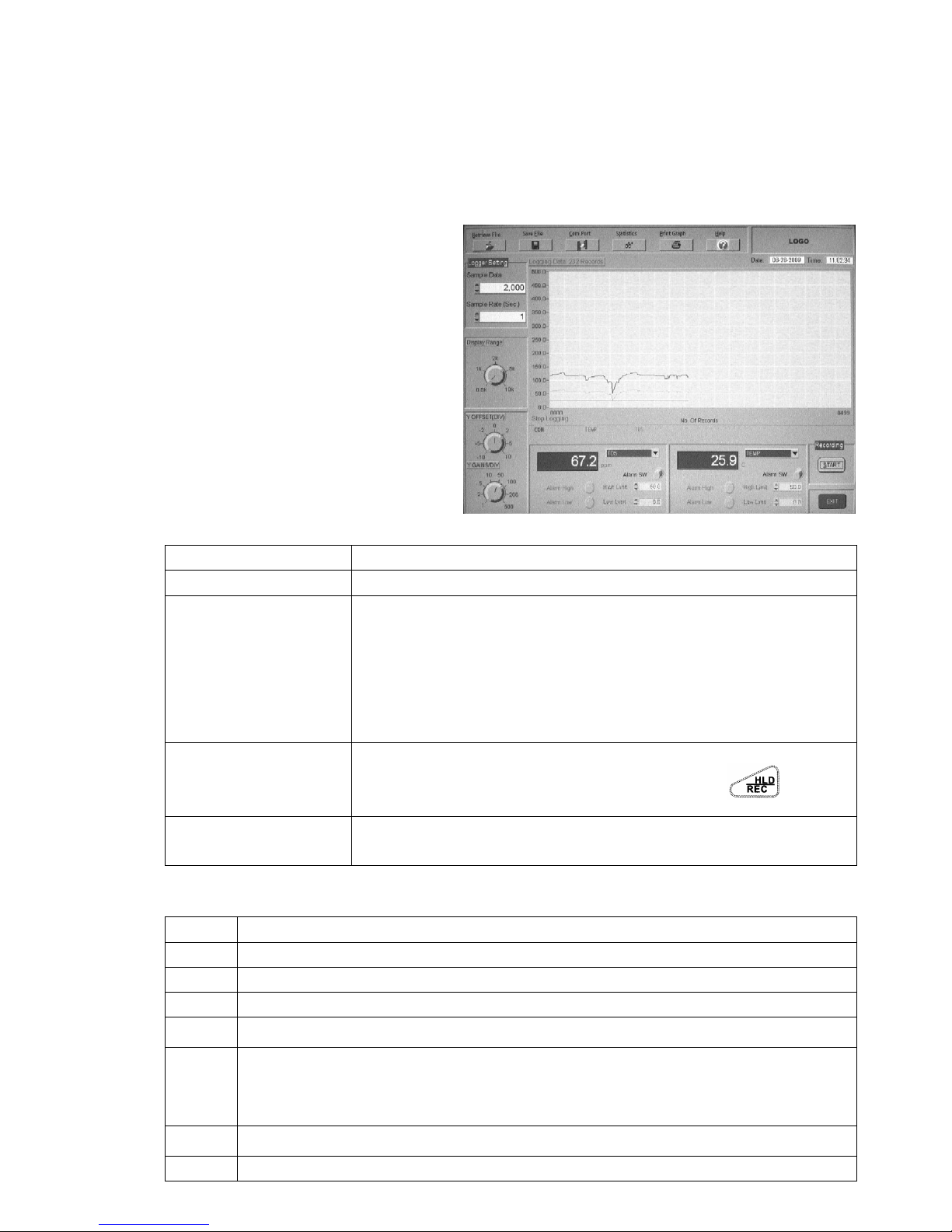
14.1 This unit can be linked to any computer via the RS232 connection port
to perform real time online data logging on the computer.
14.2 Data will be collected at defined intervals and a graph will be plotted.
14.3 Connect the RS232 mini phone jack connector to the back of the
meter and the RS232 jack to the COM1 or 2….8 computer socket.
(optional USB connector can
be purchased and used)
14.4 Insert the PC connect CDROM to begin software
installation.
14.5 Run the setup program.
14.6 After loading completed, run
the program.
14.7 Read the instructions under
help for detail setting.
15. TROUBLESHOOTING:
Problem Cause & Remedy
Cannot switch on 1. Check A/C adaptor connection
Unstable reading
or slow response
1. Ground loop in solution – make measurement in
a cup or container.
2. Electrode is clogged.
3. Electrode could be expired.
4. Electromagnetic interference - move to another
location to perform test.
Reading does not
change
1. Broken pH glass sensor with micro-crack.
2. HOLD function is activated. Press to
release.
Wrong date &
time
Backup battery has expired. Contact your dealer to
replace new ones.
16. ERROR CODE:
Code Cause & Remedy
E02 Value is out of the lower measuring range
E03 Value is out of the upper measuring range
E04 Original data error – return for repair
E12
Factory calibration error – Perform Master Reset page 9
rst
rstrst
rst
E13 Slope or Offset is out of range
– Wrong pH buffer/standard use or defective electrode.
– Perform Master Reset page 9
rst
rstrst
rst
if problem persist.
E31
Measuring circuit failure – Perform Master Reset page 9
rst
rstrst
rst
E32 IC memory failure – return for repair
Page 16

15
WARRANTY:
Trans Instruments (Singapore) Pte. Ltd., warranties this product for a
period of 12 months for main unit and 3 months for probe or sensors from
date of purchase; against all defects in material and workmanship. This
warranty does not apply to the abuse or misuse of the instrument. If
repairs or adjustments are required, please return the defective product
freight prepaid. Instrument within warranty will be repaired at no
charge.
Make sure that the product is properly packed and insured against
possible damage or loss in shipment. Purchase invoice MUST be
accompanied in returned product or else warranty is considered void.
Please obtain authorization from Trans Instruments (Singapore) Pte Ltd.
Directly or through your local sales representatives prior to returning the
product. Trans Instruments staff can be contacted at the following email
address or through our web-page contacts:
(Singapore) Pte Ltd
email: [email protected]
Website: www.transinstrumnets.com
ISO9001 Certified Firm
Rev-4 July2014
PRINTED IN SINGAPORE
Quality checked in Singapore
CALIBRATION CERTIFICATE
Product: Professional Bench-top pH meter BP3001
Measuring range: 0 to 14 pH
Calibration point(s): 7.00, 4.01, 10.01
Test point(s): 7.00, 4.01, 10.01
Accuracy achieved: ±0.02 (Complete system, meter + probe)
CL Teh
Trans Instruments (S) Pte. Ltd.
certified that the above products underwent stringent
calibration in accordance with Trans Instruments product manufacturing standards
and work procedures and the result of inspection or
testing for calibration meets the
product specifications above. The standard solutions use for the calibration
procedure was tested by instrument which is traceable to the US National Institute
for Standards & Technology standard, under ambient conditions.
This certificate validates the product at the point of production. A complete pH
system will require regular calibration from time to time. A traceable pH b
uffer
solution should be used for continual re-calibration.
 Loading...