

DAS-2420
2.4 GHz Wireless Digital Audio Sender
with Portable Receiver
In the scenario, when you want to watch your favorite action movie at night, and all your
family members were sleep, you do not want to wake them up at this time, The DAS-2420
is the best solution. DAS-2420 deploy the 2.4GHz ISM band with frequency hopping and
WiFi auto-detection scheme to provide crystal clear audio.
Feature
z 2.4GHz ISM band
z ID Pairing
z 34 channels Frequency hopping
z 1Æ1, 1ÆN Application
z Portable receiver with batteries powering and DC adaptor powering
z Frequency hopping to avoid co-channel interference
z Volume controllable via rotatable switch
z 44.1KHz sampling frequency
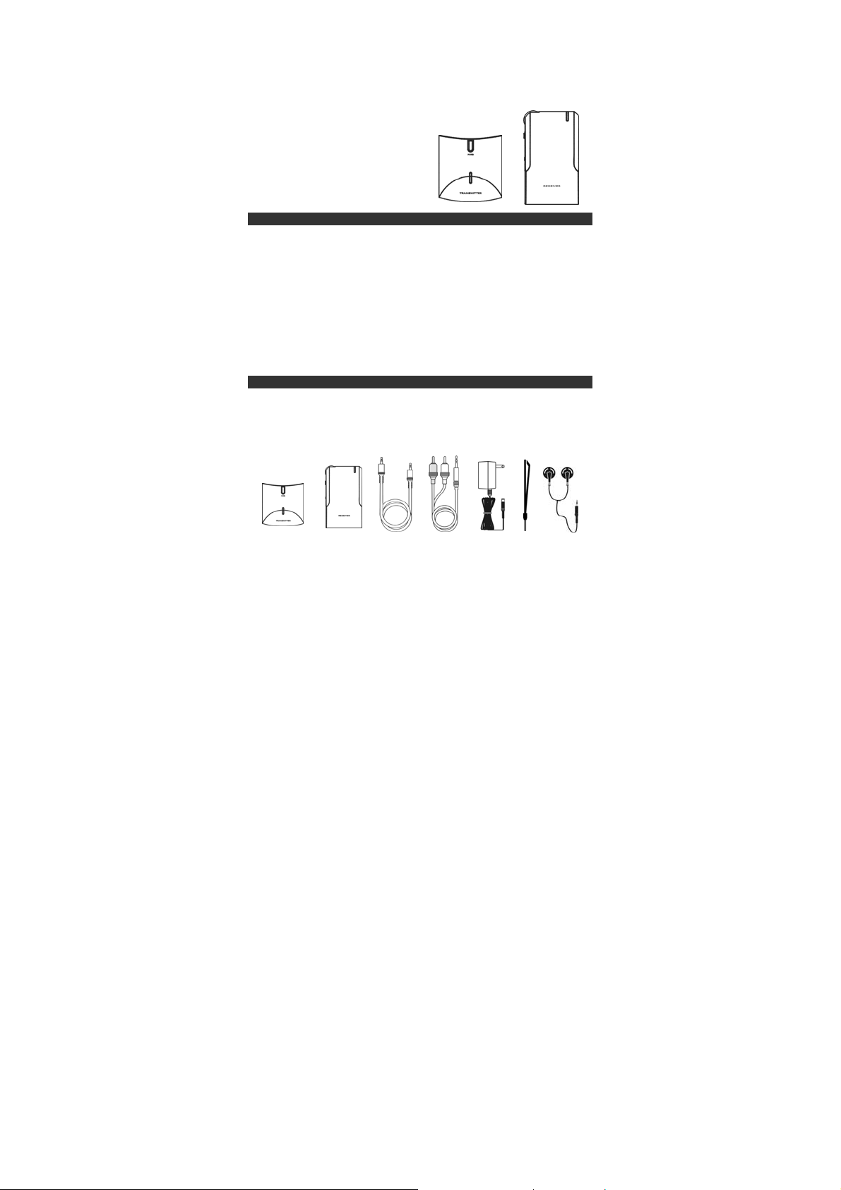
Before your installation, please check the content of package
z DAS-2420 Tx X1
z DAS-2420 Rx X1
z AC/DC Adaptor X2
z 3.5 mm to RCA R/L audio cable X1
z Stereo 3.5mm Cabel
z Earphone X1
Transmitter Receiver Stereo 3.5 Cable Audio cable Adaptor strap earphone
Introduction
Package of content
1
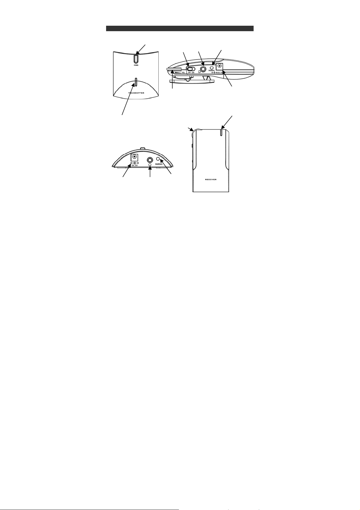
Power Switch
LED Lamp
DC Power
Transmitter
Connectors and control
Power Switch
Volume
Volume
Audio
Pairing
Switch
2
Audio
Receiver
Pairing Switch
DC Power input
LED Lamp

Federal Communication Commission Interference Statement
This equipment has been tested and found to comply with the limits for a Class B digital
device, pursuant to Part 15 of the FCC Rules. These limits are designed to provide
reasonable protection against harmful interference in a residential installation. This
equipment generates, uses and can ra diate radio frequency energy and, if not instal l ed an d
used in accordance with the instructions, may cause harmful interference to radio
communications. However, there is no guarantee that interference will not occur in a
particular installation. If this equipment does cause harmful interference to radio or
television reception, which can be determined by turning the equi pmen t of f and o n, the us er
is encouraged to try to correct the interference by one of the following measures:
z Reorient or relocate the receiving antenna.
z Increase the separation between the equipment and receiver.
z Connect the equipment into an outlet on a circuit different from that to which the
receiver is connected.
z Consult the dealer or an experienced radio/TV technician for help.
FCC Caution: Any changes or modifications not expressly approved by the party
responsible for compliance could void the user's authority to operate this equipment.
This device complies with Part 15 of the FCC Rules. Operation is subject to the following
two conditions:
(1) This device may not cause harmful interference, and
(2) This device must accept any interference received, including interference that may
cause undesired operation.
RISK OF EXPLOSION IF BATTERY IS REPLACED BY AN INCORRECT TYPE.
DISPOSE OF USED BATTERIES ACCORDING TO THE INSTRUCTIONS
CAUTION
CAUTION
3

Before your operation, please read this man ual car efully and k eep th is for furth er r eference.
Application 1: Listen to the TV sound without turn the volume of TV loudly.
Tx installation
Step1: Take out the main unit
Step2: Take a 3.5mmÆAudio RL cable, connect the 3.5mm connector to the 3.5mm socket
Step3: Take out the AC/DC adaptor, plug the barrel end to the DC socket of DAS-2420, the
Rx installation
Via AA Batteries powering
Step1: Take out the Rx unit
Step2: open the batteries compartment
Step3: Install 2 new AA batteries as figure shown (please make sure the polarity)
Step4: Close the Batteries compartment
In this scenario, the Tx unit should be located around the TV set
on the Tx unit, another RL connector to the “Speak er ou t” or “ l ine out” of your TV set
AC blade end to your AC outlet, please be noted, DO NOT OVERLOAD YOUR AC
OUTLET.
Batteries
Installation Illustratio n
DC jacket
Close the compartment
Speaker out/line out
Finished
4

Via AC/DC Adaptor
Volume
Step1: Take out the Rx unit
Step2: Take out the AC/DC adaptor included
Step3: Connect the DC barrel end to the DC socket of RX
Step4: Connect the AC blade end to your AC outlet, please be noticed, DO NOT
OVERLOAD YOUR AC Outlet
Note: When you using AC/DC Adaptor, the power from batteries is cut.
Strap for hanging
Please take the strap and fasten it on the receiver unit like followed illustration picture.
DC jacket
AC adaptor
5

r
When All the connection are finished, you can start to use this wireless audio sender
system as followed steps
Step1: Power on the Tx (press the power switch on the Tx)
Step2: Power on the Rx unit via sliding the Power key on the RX unit
Power Switch
Step4: Turn the Volume of Rx to the lowest value
Step5: Connect the earphone to the Audio socket on the RX unit
Step6: You hav e finished all the setting , a nd you can listen to the TV sound no w , an d
you can adjust the suitable volume for yourself.
Operation
Power Switch
Earphone Earphone Speake
6

The DAS-2420 is designed to work with various Rx s, it can be con figured to w ork with mor e
than 16 Rxs (within the transmission distance).
How to add a new Rx
Step1: Power the Transmitter unit, press the power switch.
Step2: Power on the Receiver unit, slide the power switch.
Step3: Press Pairing key on the transmitter for 3 Secs. Transmitter will be under pairing
mode, the LED on Tx will be blinking.
Step4: Press the pairing key on receiver for 3 Secs, Tx and Rx are under pairing mode.
The LED on Rx will be blinking.
Power Switch
Step5: When the pairing procedure is ok, LED on Tx and Rx will dimmed at the same time,
Pairing is OK. It will take 10 sec to do the pairing.
No audio output
1. Check the power of Tx and Rx.
2. Check the audio connection on Tx and Rx.
3. Check the LED light on Tx, if there is audio presented, the LED will be lighted, if it is
blinking that is means that there is no audio presented in Tx.
There is some noise
1. Check the Tx and Rx are in the range of specification
2. Check if there are obstacles in the transmission range, such as microwave oven. Etc
3. press the pairing key once to check if there is interference again.
ADDING A NEW RX
Power Switch
FAQ
7

SAFETY NOTICE
z INDOOR USE ONLY.
z THIS DEVICE WITH WIRELESS RF SIGNAL RECEPTION,CONSULT YOUR
DOCTOR IF YOU WEAR PACEMAKER.
z IF YOU GO OUT FOR MORE THAN 2 WEEKS, PLEASE TAKE THE BATTERIES OUT
FROM YOUR RX UNIT.
z CLEAN WITH DRY AND SOFT CLOTH.
z DO NOT OPEN THE UNIT.
z NO SERVICEABLE PARTS FOR CUSTOMER.
z DO NOT USE THIS UNIT IN THE HOT AND DAMP PLACE.
Description Transmitter Receiver
Operating temperature 0 ~ +60 (degrees Celsius) 0 ~ +60 (degrees Celsius)
Frequency range 2406 ~ 2472 MHz 2406 ~ 2472 MHz
Modulation GFSK
Channels 34
TX Power 15 dBm
Input impedance >10K Ohm (3.5mm)
Input level 2Vp-p (Max)
RX Sensitivity -78 dBm (Min.)
Output impedance 16 Ohm (Nominal)
Output level 2Vp-p (Max)
Transmit Distance Between
Tx & Rx
Response (station) 20 ~ 20 KHz, ±0.5dB
Crosstalk -70dB (Min)
S/N ratio (station) 70dB (Min)
THD + N 5% (Max)
Power supply
NOTE: The changes or modifications not expressly approved by the party responsible for
compliance could void the user’s authority to operate the equipment.
To avoi d the i nter feren ce, pl ease far aw ay the sources of i nter ferenc e such as w ir eless LAN
AP, Microwave OVEN etc
Digital Audio Sender Specifications
Model NO. Transmitter RECEIVER
100ft(Min, LOS)
AC 90~240V@50/60Hz/DC 5V, 1000mA
PLUG: 5.5mmx2.1mmx11mm
Polarity: Outside Jack(-) Inside Jack(+)
8

Federal Communication Commission Interference Statement
This device complies with Part 15 of the FCC Rules. Operation is subject to
the following two conditions: (1) This device may not cause harmful
interference, and (2) this device must accept any interference received,
including interference that may cause undesired operation.
This equipment has been tested and found to comply with the limits for a
Class B digital device, pursuant to Part 15 of the FCC Rules. These limits
are designed to provide reasonable protection against harmful interference in a
residential installation. This equipment generates, uses and can radiate radio
frequency energy and, if not installed and used in accordance with the
instructions, may cause harmful interference to radio communications.
However, there is no guarantee that interference will not occur in a particular
installation. If this equipment does cause harmful interference to radio or
television reception, which can be determined by turning the equipment off
and on, the user is encouraged to try to correct the interference by one of the
following measures:
- Reorient or relocate the receiving antenna.
- Increase the separation between the equipment and receiver.
- Connect the equipment into an outlet on a circuit different from that
to which the receiver is connected.
- Consult the dealer or an experienced radio/TV technician for help.
FCC Caution: Any changes or modifications not expressly approved by the
party responsible for compliance could void the user's authority to operate this
equipment.
This transmitter must not be co-located or operating in conjunction with any
other antenna or transmitter.
FOR MOBILE DEVICE USAGE (>20cm/low power)
Radiation Exposure Statement:
This equipment complies with FCC radiation exposure limits set forth for an
uncontrolled environment. This equipment should be installed and operated
with minimum distance 20cm between the radiator & your body.
 Loading...