

Page 1
TRANSDUCTION
USER’S MANUAL
Version 1.2
07/30/08
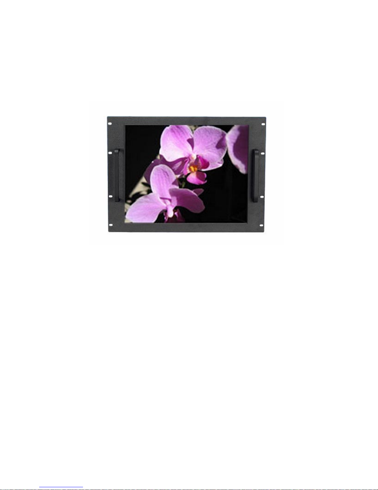
TR-LCD1900-RM Rack Mount Monitor
TR-LCD1900-PM Panel Mount Monitor
5155-23 Spectrum Way, Mississauga, ON, Canada L4W 5A1
TEL: 1-800-268-0427, 905-625-1907
FAX: 905-625-0531
Email: [email protected]
Page 2

Important Information
The information in this document is subject to change without notice.
All relevant issues have been considered in the preparation of this document. Should you notice an omission or
any questionable item in this document, please feel free to notify Transduction.
Regardless of the foregoing statement, Transduction assumes no responsibility for any errors that may appear in
this document nor for results obtained by the user as a result of using this product.
Copyright © 2005 Transduction. All rights reserved.
This document is protected by copyright. No part of this document may be reproduced, copied or translated in any
form or means without prior written permission from Transduction.
All other trademarks, brand and product names are the property of their respective owners.
Return policy
Products returned for repair must be accompanied by a Return Material Authorization (RMA) number, obtained
from Transduction prior to return. Freight on all returned items must be prepaid by the customer. The customer is
responsible for any loss or damage caused by the carrier in transit.
To obtain an RMA number, call us at 905-625-1907. We will need the following information:
• Return company address and contract
• Model name, model number and serial number
• Description of the failure
Mark the RMA number clearly on the outside of each box, include a failure report and return the product to:
Transduction
5155 – 23 Spectrum Way
Mississauga ON Canada L4W 5A1
Attn: RMA Department
Page 3

Safety Precautions
When not used for extended periods of time, set your PC to DPMS. If using a
screen saver, set it to the active screen mode.
Do not use a damaged or loose plug. This may cause an electric shock or fire.
Do not pull the plug out by the wire or touch the plug with wet hands. This may
cause an electric shock or fire.
Use only a properly grounded plug or receptacle. An improper ground may
cause electric shock or equipment damage.
Do not excessively bend the plug and wire or place heavy objects on them. This
could cause damage and an electric shock or fire.
Do not place the monitor face down. The CDT surface may be damaged.
When cleaning, wipe with a slightly moistened, soft cloth. Do not spray any
cleaner directly on to the monitor.
Do not remove housing. No serviceable parts inside. Refer servicing to Trans-
duction.
1 TR-LCD1900
Page 4
Contents
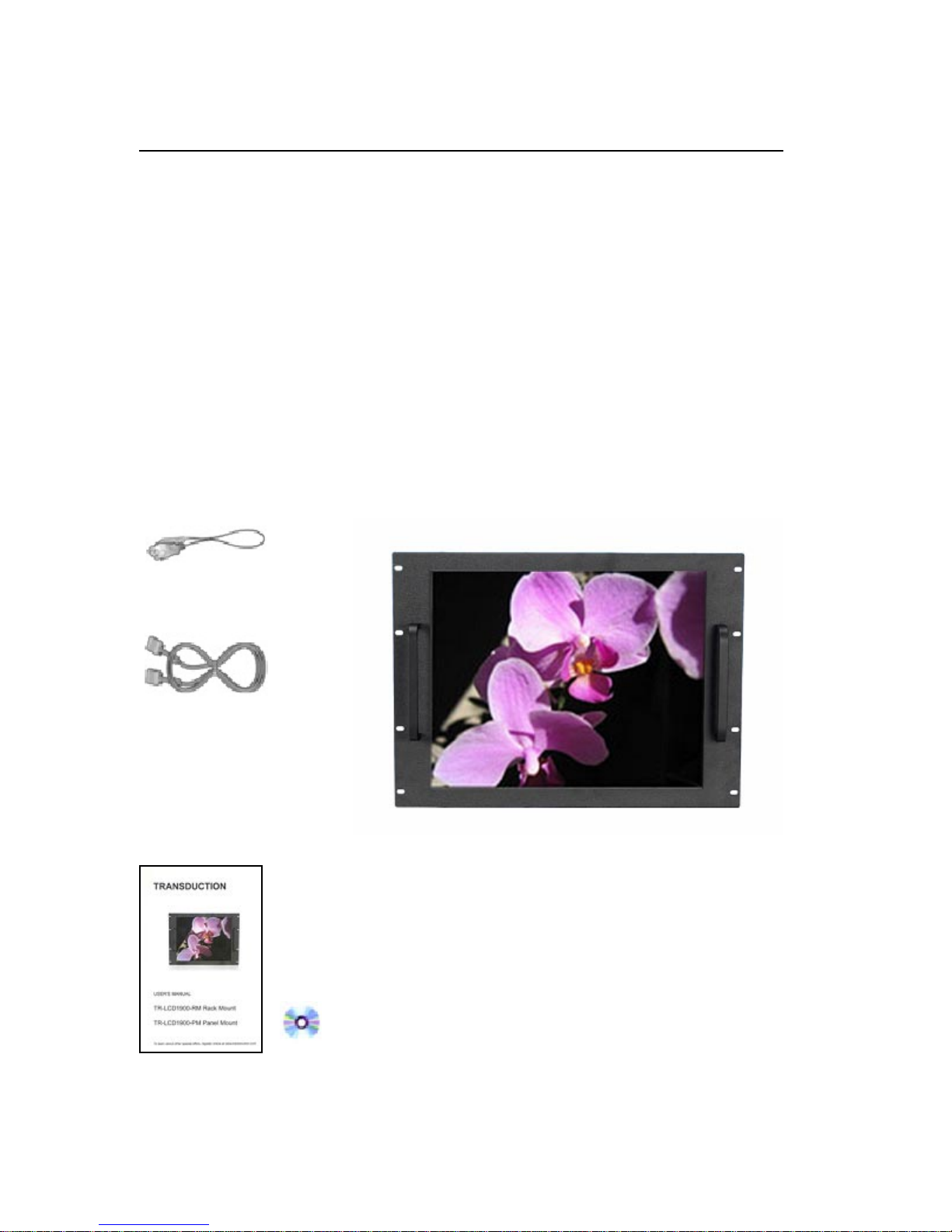
Your new TR-LCD1900 monitor box should contain the
following:
• TR-LCD1900 rack mount / panel mount monitor
• Power Cord
• Video Signal Cable
• User’s Manual and Driver Installation CD
*Remember to save your original box and packing material to transport or ship the monitor.
Power Cord
Video Signal Cable
User’s Manual and Driver
Installation CD
2 TR-LCD1900
Page 5
Quick Start
To attach the TR-LCD1900 monitor to your system, follow these instructions:
1. Turn off the power to your computer.
2. Connect the power cord for your monitor to the power port on the back of the monitor. Plug the power
cord for the monitor into a nearby outlet.
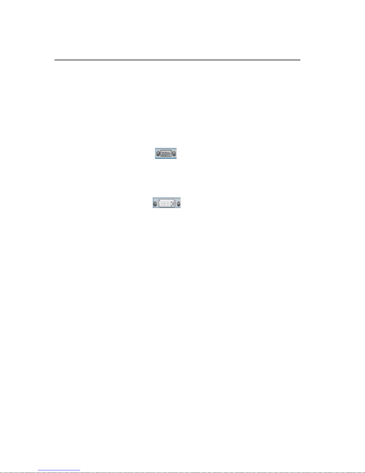
3-1. Using the D-sub (analog) connector on the video card:
Connect the signal cable to the 15-pin, D-sub connector on the back of your monitor.
3-2. Using the DVI (digital) connector on the video card:
Connect the DVI cable to the DVI port on the back of your monitor.
4. Connect to a Macintosh:
Use the D-sub connection cable.
(An older model Macintosh may require a special Mac adaptor).
5. Turn on your computer and monitor. If your monitor displays an image, installation is complete.
NOTES:
• You may get a blank screen depending on the type of video card you are using, if you connect
simultaneously both D-sub and DVI cables to one computer.
• If the monitor is connected properly using the DVI connector but you get a blank or fuzzy
screen, check to see if monitor status is set to analog. Press Source button to have the monitor
double-check the input signal source.
3 TR-LCD1900
Page 6
Control Panel Buttons
Key Name and Function
The Control Panel Buttons give various and very easy graphic user interfaces. Users can easily
access the function needed. Be sure that your system power and LED is turned on before operating
the keyboard.
Key Name Description
Power Turns ON/OFF the system
Menu Activates the OSD menu or goes to previous menu
Auto -When the OSD menu is off, press more than 3 seconds
: Performs “Auto-adjustment” function
-When the OSD menu is on
: Selects the highlighted icon that user wants
Down Moves the highlight icon up to the function that user wants
Up Moves the highlight icon down to the function that user wants
Left Decreases the adjustment of the selected function
Right Increases the adjustment of the selected function
Source Selects the Input Signal among analog RGB, Digital DVI, CVBS and S-VHS
Accessing the menu system
1. With the OSD off, push the Menu button to activate the main OSD menu.
2. Use the Up or Down buttons to move from one function to another. As you move from one
icon to another, the function name changes to reflect the function or group of functions
represented by that icon. Please refer to the following table for a complete list of all of the
functions available for the driver board.
3. Press the Set button once to activate the highlighted function, use the Up or Down buttons to
select the function.
4. After selecting a function, use the - or + buttons to make optimum adjustments. The setting bar
moves and the numeric value indicator changes to reflect your adjustments.
Note: The numeric value indicator is provided as a point of reference only and has nothing to
do with a real measurement.
5. Press the Menu button once to return to the main menu to select another function or press
twice to exit from the OSD.
4 TR-LCD1900
Page 7
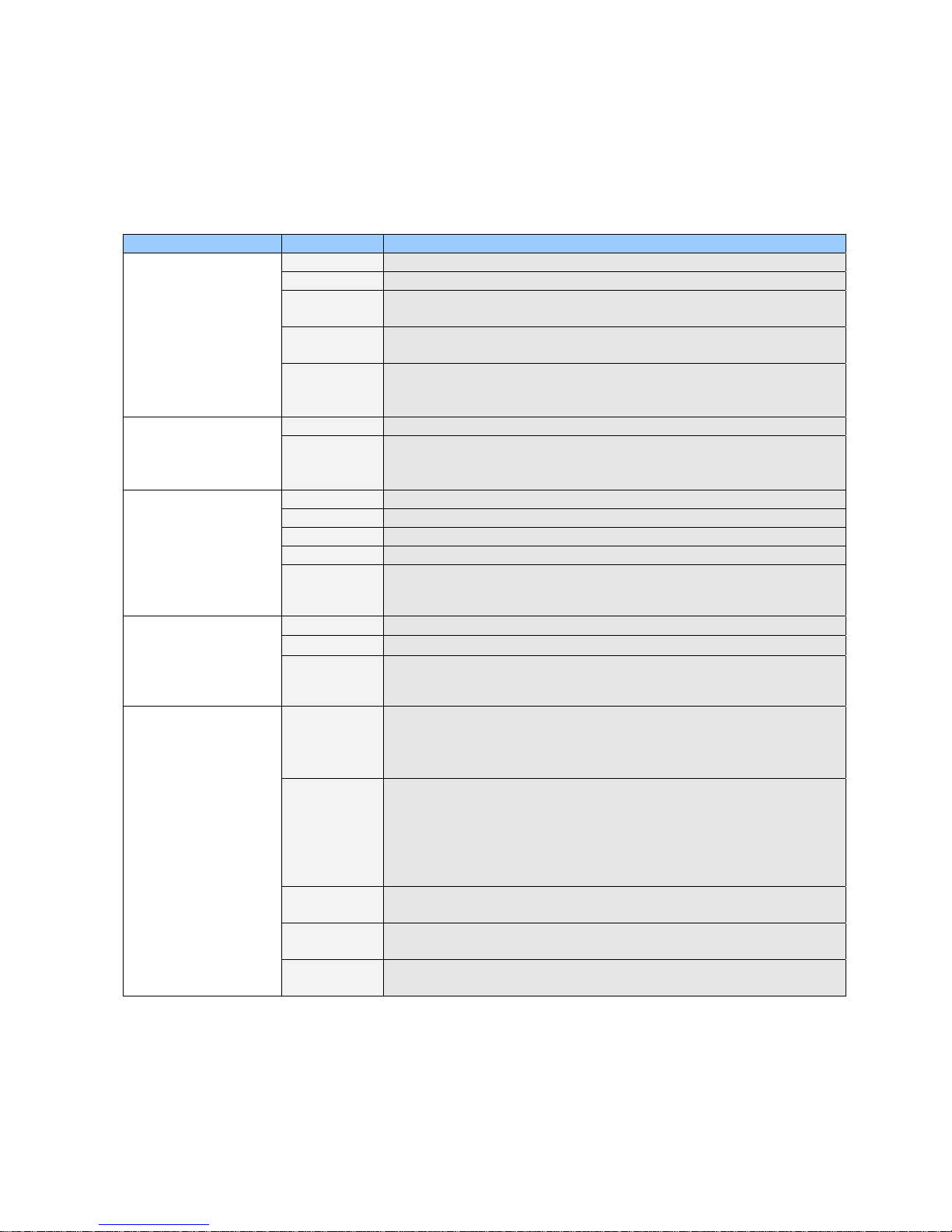
Control Panel Buttons cont’d
OSD Adjustment
Color
Setup
Sub-menus Function Descrip t io ns
Brightness Adjusts the brightness of video.
Contrast Adjusts the cont r ast of video.
Clock Removes the noises. When frequency value is wrong, the image
has horizontal lines especially in 1 dot on and off.
Phase Rem ov es the noises. When phase value is wrong, t he im age
has vertical lines especially in 1 dot on and off.
Auto Adjust “Auto adju stm ent” allows the monitor to self- adjust to the
incoming video signal. The value of phase, frequency and
position ar e adjusted automatically .
Contrast Adjusts the cont r ast of image.
Brightness Adjusts the brightness of image.
Brightness Adjusts the brightness of video.
Contrast Adjusts the cont r ast of video.
Color Changes the ri c hness of c olor.
Tint Changes the tone of c olor .
Sharpness Adjusts the sharpness of video image.
6500° K
9200° K
User User customi z able.
Image -H Position : Adjusts the horizontal position of the image.
OSD -Language : Engl ish, Germany, French, Italy, Spanish.
Mode
Recall
Backlight Changes the bri ghtness of image by controlling the backlight of
Auto sleep Goes to soft power off after 10 minut es when input c able is
Reddish white.
Bluish white.
-V Position : Adjusts the vertical position of the image.
-GAMMA : Bypass
-Information : Displays current di splay mode.
-Color : Changes the opaquene s s of the OSD background.
-Position : Moves the OSD Window.
-Duration : Indicates time until the OSD Menu will disappear
after adj usting the menu.
-OSD Lock : Avoids OSD control except HOT key.
Changes the im age information to factory outgoing status.
panel.
disconnected.
Menus
Adjustment (PC)
Adjustment is used
to fine tune and get
the best image by
removing noises
that creates
unstable images
with jitters and
shimmers.
Adjustment (DVI)
This function is
active if you select a
digital DVI source
Adjustment
(Video)
This function is
active if you select
an input source
other than PC.
(DVD,VCR)
The color can be
changed from
reddish to bluish
white.
Setup is used to
adjust OSD menu
information and
image.
5 TR-LCD1900
Page 8
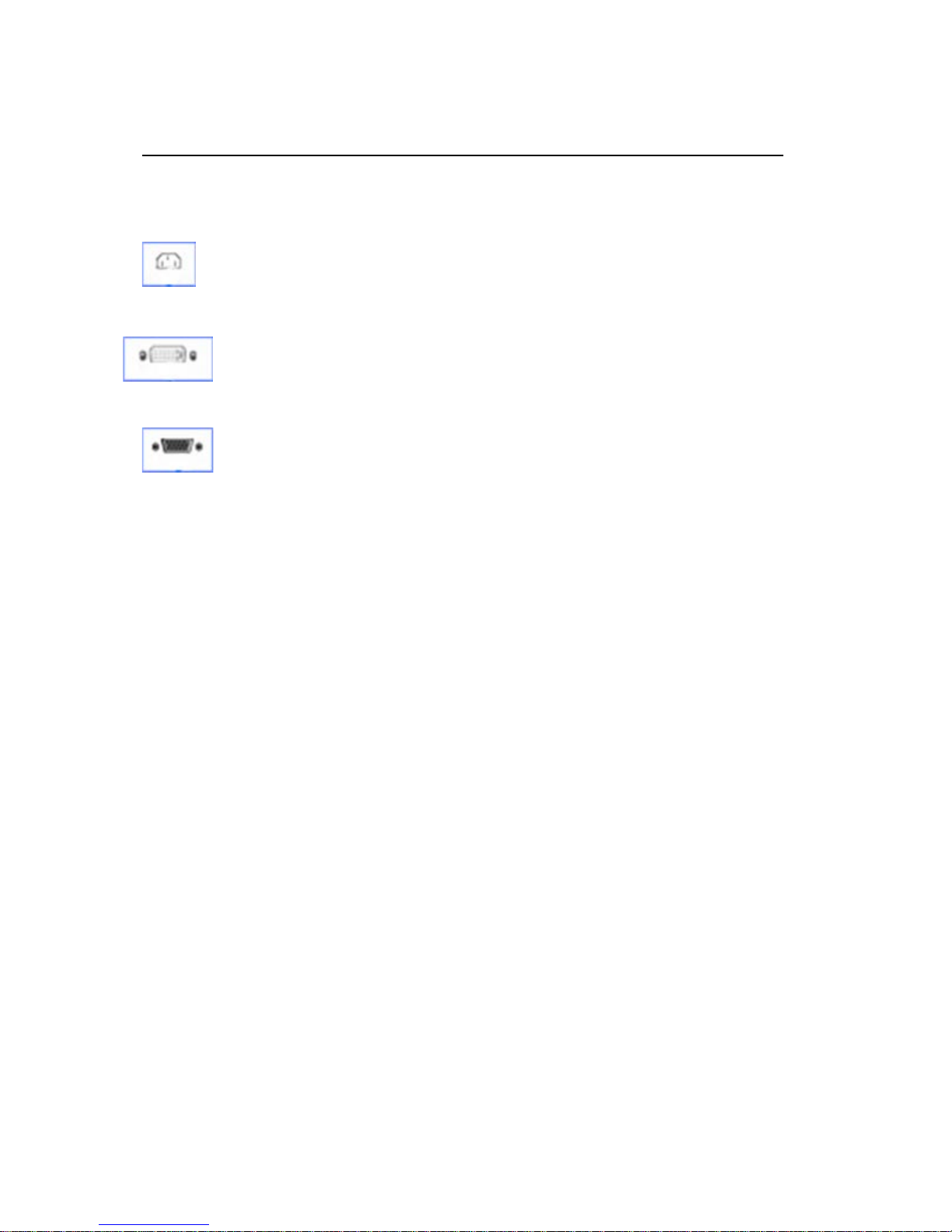
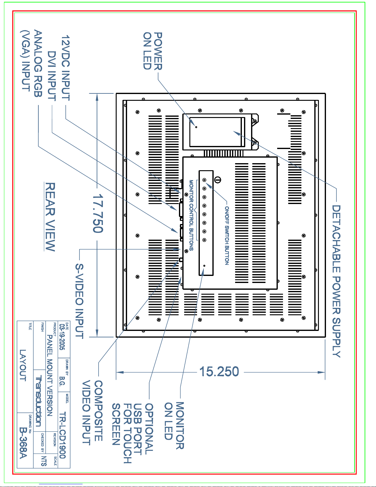
Rear Panel Connectors and On/Off Switch
(The configuration at the back of the monitor may vary from product to product.)
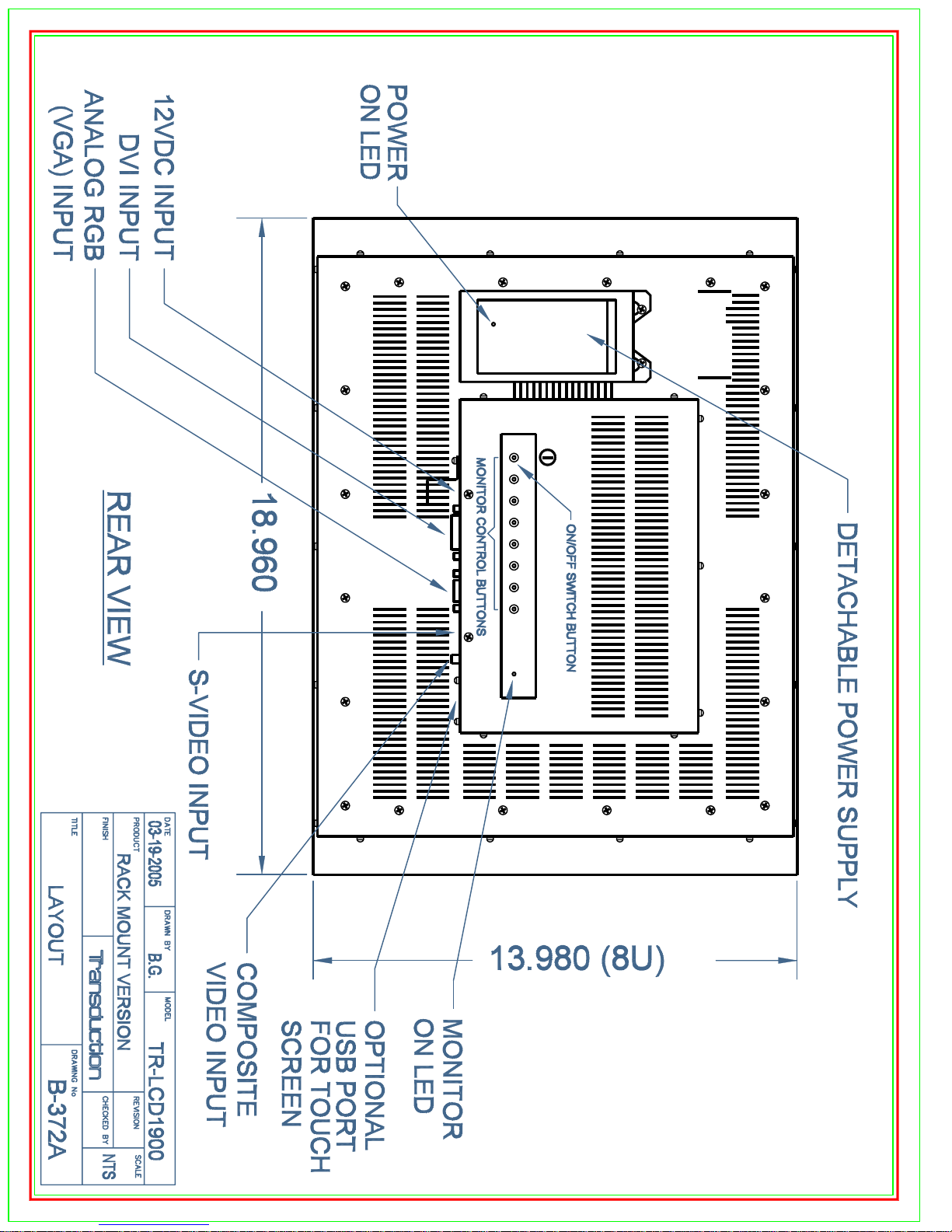
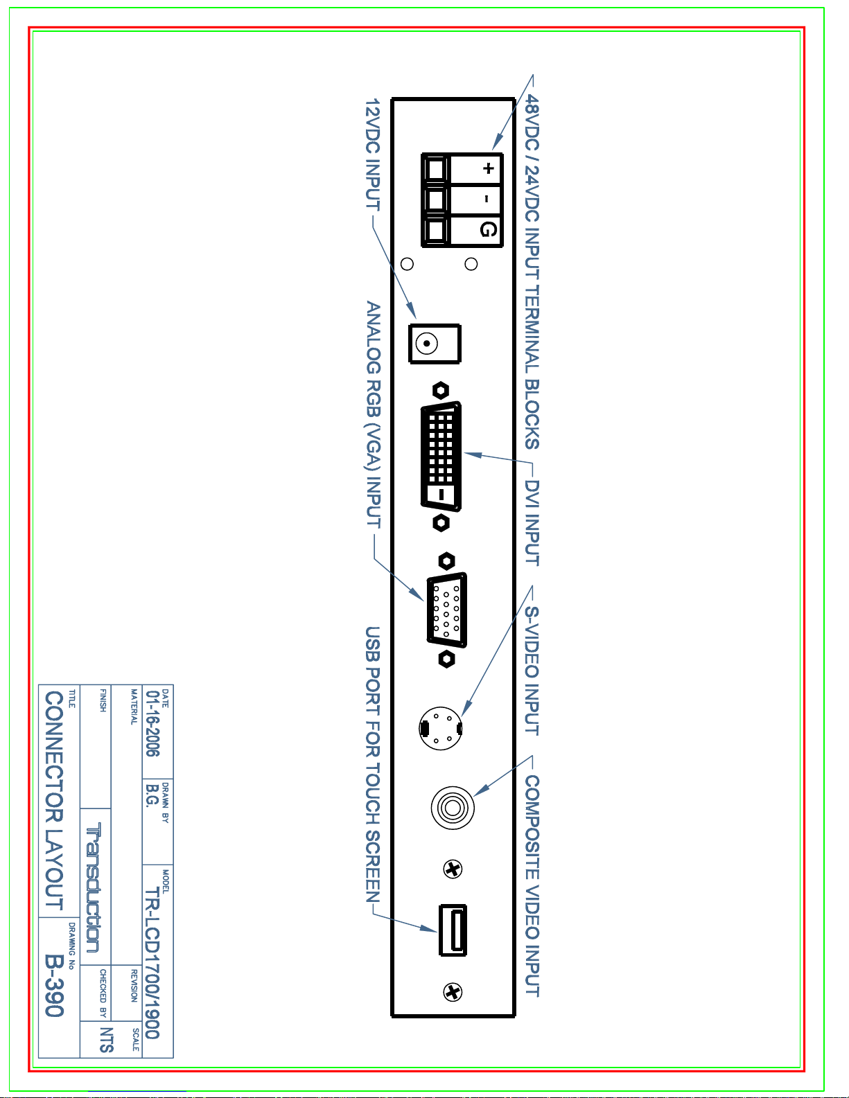
1 Power port Connect the power cord for your monitor to the power
port on the back of the monitor.
2 DVI port Connect the DVI Cable to the DVI Port on the back of
your Monitor.
3 Signal port Connect the signal cable to the 15-pin, D-sub connector
on the back of your monitor.
Note: See Quick Start on page 4 for further information regarding cable connections.
6 TR-LCD1900
Page 9
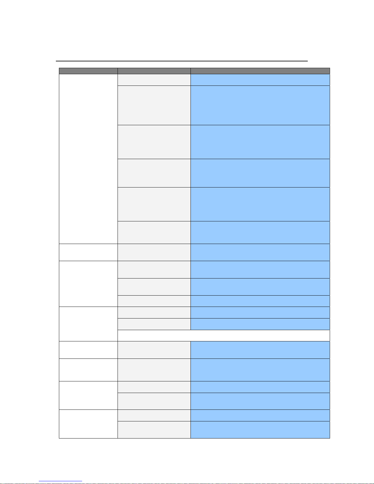
Troubleshooting Tips
Before calling for service, check the information
in this section to see if you can remedy any
problems yourself. If you do need assistance,
please contact Transduction.
Symptom Check List Solutions
No images on the screen. I
cannot turn on the
monitor.
I cannot see the On Screen
Display.
The screen sho ws strang e
colors or just black and
white.
The screen sudden l y has
become unbalanced.
The screen is out of focus
or OSD cannot be
adjusted.
LED is blinking but no
images on the screen.
There are only 16 colors
shown on the screen. The
screen color s have
changed after ch angi ng
the video card.
reads “Unrecog niz ed
monitor, Plug & Play
(VESA DDC) monitor
found”.
Is the power cord connect ed
properly?
Can you see “No Connection,
Check Signal Cable” on t he
screen?
If the power is on, reboot the
computer to see the initial screen
(the login screen), whic h can be
seen.
Can you see “Video mode not
supported” on the screen?
There is no image on the screen. Is
the power indicator on the m onit or
blinking at 1 second interv als ?
Connected using the D VI cable? You may get a blank screen if you boot t he system before you connect the
Have you locked the On Scr een
Display (OSD) M enu to prevent
changes?
Is the screen displaying only one
color as if looking at the screen
through cellophane paper?
Have the screen colors bec om e
strange after running a program or
due to a crash between applic at ions ?
Has the video card been set
properly?
Have you changed the v ideo c ard or
the driver?
Have you adjusted t he res olut ion or
frequency to the monitor?
The screen can be unbal an ced due to the cycl e of the video card si gnal s. Readju st Po si tion by referri ng to
the OSD or MagicTune.
Have you adjusted t he res olut ion or
frequency on the monit or?
Is the frequency properly adjus t ed
when checking the D isplay T iming on
the menu?
Have the Windows colors been s et
properly?
Has the video card been set
properly?
Have you installed t he monitor
driver?
See the video card manual to s ee if
the Plug & Play (VESA DDC)
function can be support ed.
Check the power cord connec t ion and s upply .
(Connected u sing the D -sub cab l e)
Check the signal cable connec t ion.
(Connected u sing the D VI cabl e)
If you still see an (error) message on t he screen w hen t he m onit or is
connected properly, c hec k to see if the monitor s t atus is set t o analogue.
Press Source button t o hav e the monit or double-c hec k the input signal
source.
If the initial screen (the login screen) appears , boot t he computer in the
applicable mode (the safe m ode f or W indow s ME/2000/XP) and then
change the frequency of the video card.
(Refer to the Preset Dis play Modes page 32)
Note: If the initial screen (the login screen) does not appear, c ont act a
service center or your dealer.
You can see this message w hen t he signal from the video card exceeds
the maximum res olut ion and f requenc y that the monitor can properly
handle.
Adjust the maxim um resolut ion and f requenc y that the monitor can
properly handle.
The monitor is in PowerSav er m ode.
Press a key on the keyboard or m ov e the mous e to activat e the monitor
and restore the image on the screen.
If there is still no image, press the ‘Sourc e’ but t on. Then pres s any key on
the keyboard or move t he mouse again t o ac t ivate the monit or and restore
the image on the screen.
DVI cable, or disconnect and t hen rec onnec t the DVI cable while the
system is running as certain ty pes of graphic c ards do not s end out video
signals. Connect the DVI cable and t hen reboot the system.
Unlock the OSD by press ing t he MENU button for at least 5 seconds.
Check the signal cable connec t ion.
Make sure the video card is fully ins ert ed in its slot.
Reboot the comput er.
Set the video card by referring to t he video card m anual.
Adjust screen image pos it ion and s iz e using the OSD or MagicTune.
Adjust the resolution and f requenc y at t he v ideo c ard.
(Refer to the Preset Dis play Modes page 32).
Adjust the resolution and f requenc y of t he v ideo c ard.
(Refer to the Preset Dis play Modes page 32).
Adjust the frequency properly by referring to t he v ideo card manual and
the Preset Display Modes .
(The maximum frequency per res olut ion m ay differ f r om produc t to
product.)
For Windows ME/ 2000/ XP:
Set the colors properly at the Control Panel, Display, Settings.
Set the video card by referring to t he video card m anual.
Install the monitor driver ac c ording t o the Driv er Inst allat ion I nstruc t ions. There is a message that
Install the monitor driver ac c ording t o the Driv er Inst allat ion I nstruc t ions.
7 TR-LCD1900
Page 10
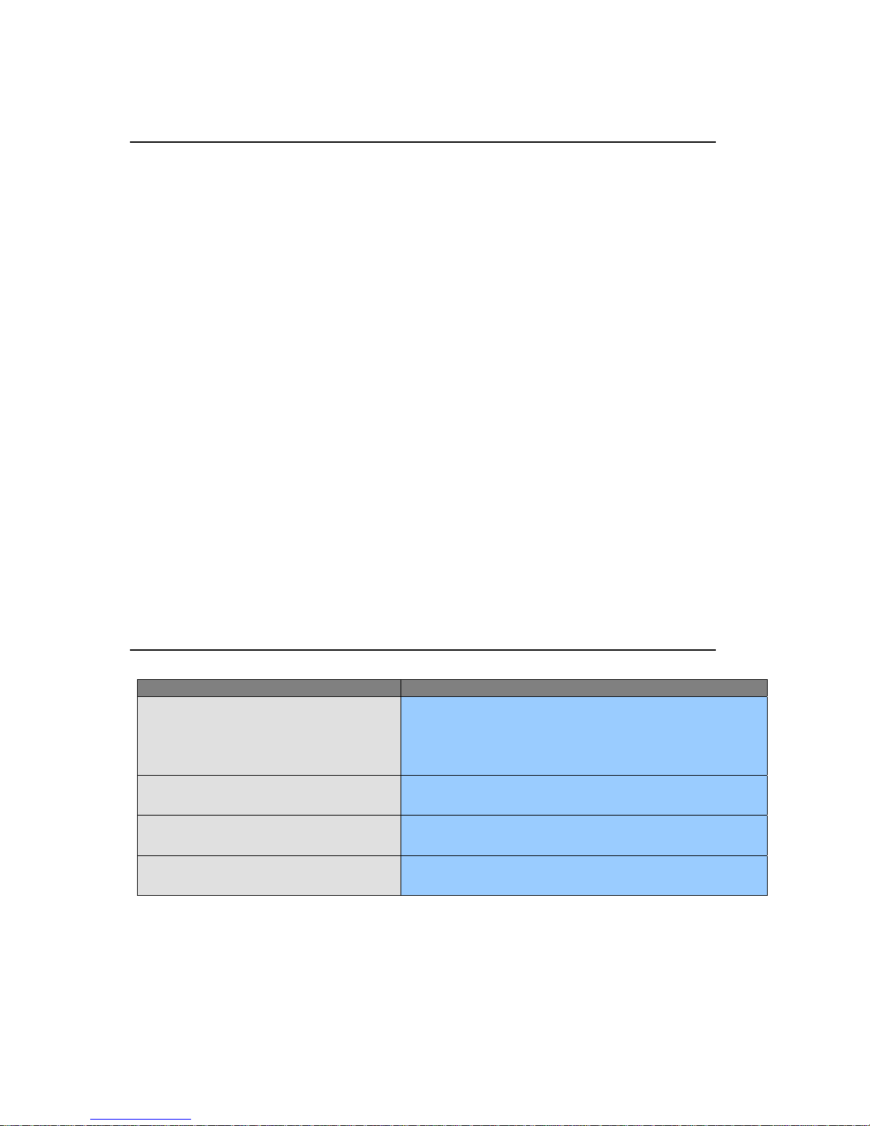
Troubleshooting Tips - cont’d
Question
Answer
Check Before Using MagicTune
TM
1. The MagicTuneTM (display adjustment) feature is not available in Game mode or Full Screen
video mode.
2. When activated in a mode in which the four edges of the display are black (Game or DOS
mode), the “Auto” feature of the LCD monitor may cause the screen to be displayed offcenter.
3. Installing the MagicTuneTM (display adjustment) software may cause a slight delay when
starting the computer.
Check the following items if there is trouble with the monitor.
1. Check if the power cord and the cable are properly connected to the computer.
2. Check if the computer beeps more than 3 times when booting.
(If it does, request an after-service for the main board of the computer.)
3. If you installed a new video card or if you assembled the PC, check if you installed the
adapter (video) driver.
4. Check if the scanning ratio of the video screen is set at 75Hz.
(Do not exceed 60Hz when using the maximum resolution.)
5. If you have problems in installing the adapter (video) driver, boot the computer in Safe
Mode, remove the Display Adapter from the hardware profile and then reboot the computer
and reinstall the adapter (video) driver.
Frequently Asked Questions
How can I change the frequency? Frequency can be changed by reconfiguring the video card.
How can I adjust the resolution? Windows ME/XP/2000 : Set the resolution at
How can I set the Power Saving function? Windows ME/XP/2000 : Set the function from the
How can I clean the outer case / LCD Panel? Clean the m onitor with a soft cloth, usi ng ei th er a cl ean ing soluti on or
Note that vid eo c ar d sup p or t c an vary, depending on the version of
the driver used.
(Refer to the computer or the video card manual for details.)
Display, Settings.
Display, Screen Saver.
plain water. Do not spray directly on to the monitor.
the Control Panel,
Control Panel ,
8 TR-LCD1900
Page 11
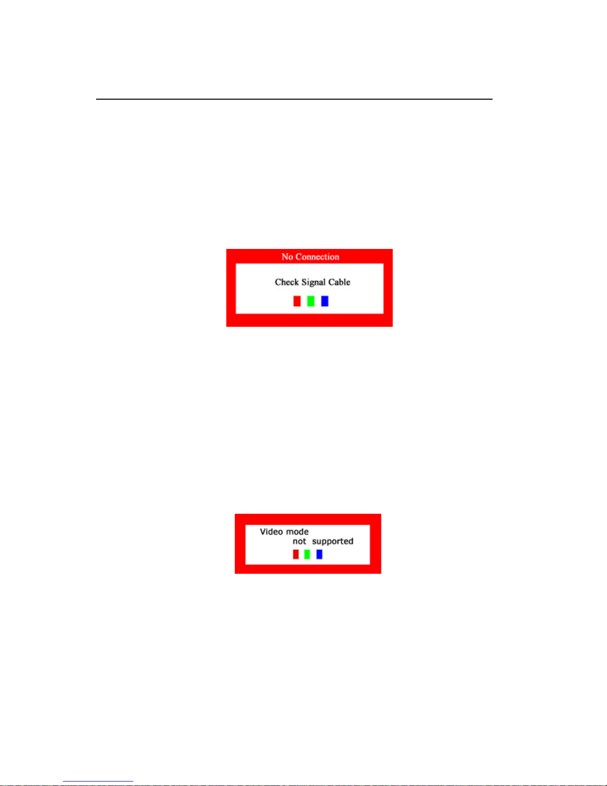
Self-Test Feature
The TR-LCD1900 has a Self-Test feature that allows you to check whether your monitor is functioning
properly.
Self-Test Feature Check
1. Turn off both your computer and the monitor.
2. Unplug the video cable from the back of the computer.
3. Turn on the monitor.
If the monitor is functioning properly, you will see a box with a border and text inside as shown in
the following illustration:
The three boxes inside the border are red, green and blue.
Failure of any of the boxes to appear indicates a problem with your monitor. This box also appears during normal operation if the video cable becomes disconnected or damaged.
1. Turn off your monitor and reconnect the video cable; then turn on both your computer and the
monitor.
If your monitor remains blank after following the previous procedure, check your video controller
and computer system; your monitor is functioning properly.
Warning Messages
If there is something wrong with the input signal, a message appears on the screen or the screen
goes blank. The message may indicate that the monitor is out of scan range or that you need to
check the signal cable.
Useful Tips
• A monitor recreates visual signals received from the PC. Therefore, if there is trouble with
the PC or the video card, this can cause the monitor to become blank, have poor coloring,
noise, Video mode not supported, etc.
• Judging the monitor’s working condition
If there is no image on the screen or “Video mode not supported” message comes up, disconnect the cable from the computer while the monitor is still powered on.
o If there is a message coming up on the screen or if the screen goes white, this means
the monitor is in working condition.
o In this case, check the computer for trouble.
9 TR-LCD1900
Page 12
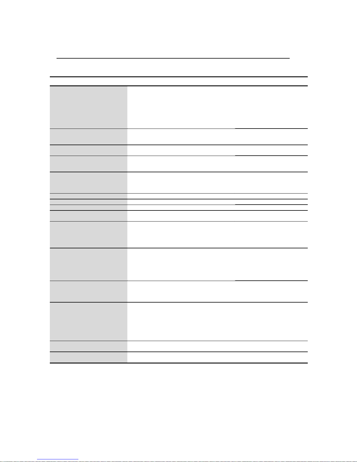
TR-LCD1900 Specifications
TR-LCD1900 Monitor Notes
LCD Module
Display Area:
Pixel Pitch:
Type:
Viewing Angle:
Brightness:
Contrast Ratio:
Synchronization
Horizontal:
Vertical:
Display Colors
Analog input:
Resolution
Optimum resolution:
Maximum resolution:
Input Signal, Terminated
Maximum Pixel Clock 140 MHz
Power Supply AC 90 ~ 264 VAC rms, 60/50 Hz ± 3Hz or optional 12VDC input
Power Consumption 42W (Maximum)
Signal Cable 15pin-to-15pin D-sub cable, detachable
Dimensions (W x D x H) / Weight
Rack mount:
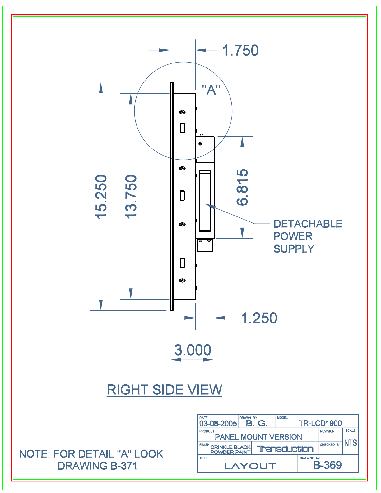
Panel mount:
Environmental Considerations
Operating Temperature:
Humidity:
Storage Temperature:
Humidity:
Plug and Play Capability This monitor can be installed on any P lug & P lay compatible system. Interaction of
Dot Acceptability TFT LCD panel is manufactured by us ing advanc ed semiconductor technology with
MagicTune Display Adjustm ent
Feature
Regulatory Approvals CSA
Note: Design and specifications are subject to change without prior notice.
Size:
19.0 inch diagonal
376.32 (H) x 301.056 (V)
0.294 (H) x 0.294 (V)
a-si TFT active matrix
80(H) / 75(V)
300 cd/m
700 : 1
30 ~ 81 kHz
56 ~ 75 Hz
16,194,277
1280 x 1024@60Hz
1280 x 1024@75Hz
RGB Analog, DVI Compliant Digital RGB.
Composite H/V Sync, S OG (option), 0.7V p-p Pos itive at 75 ohm s
Separate H/V sync, TTL level positive or negative
DVI-D to DVI-D connector, detachable
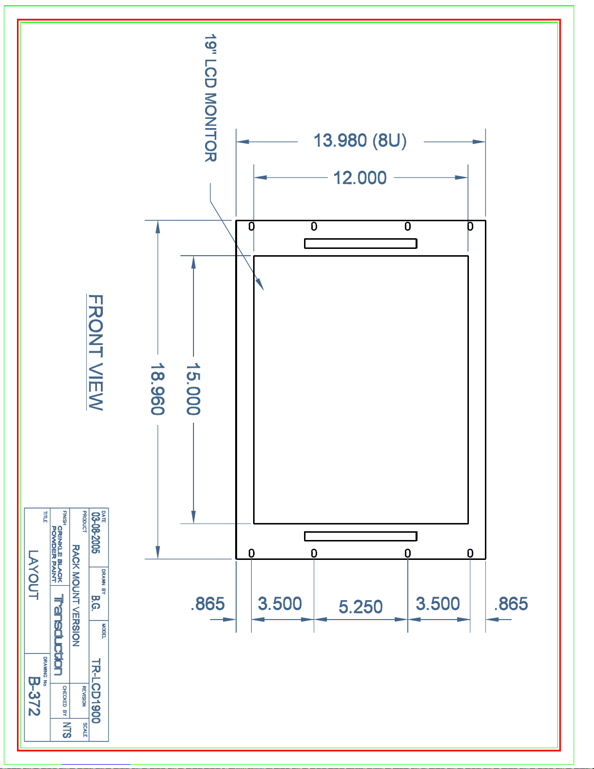
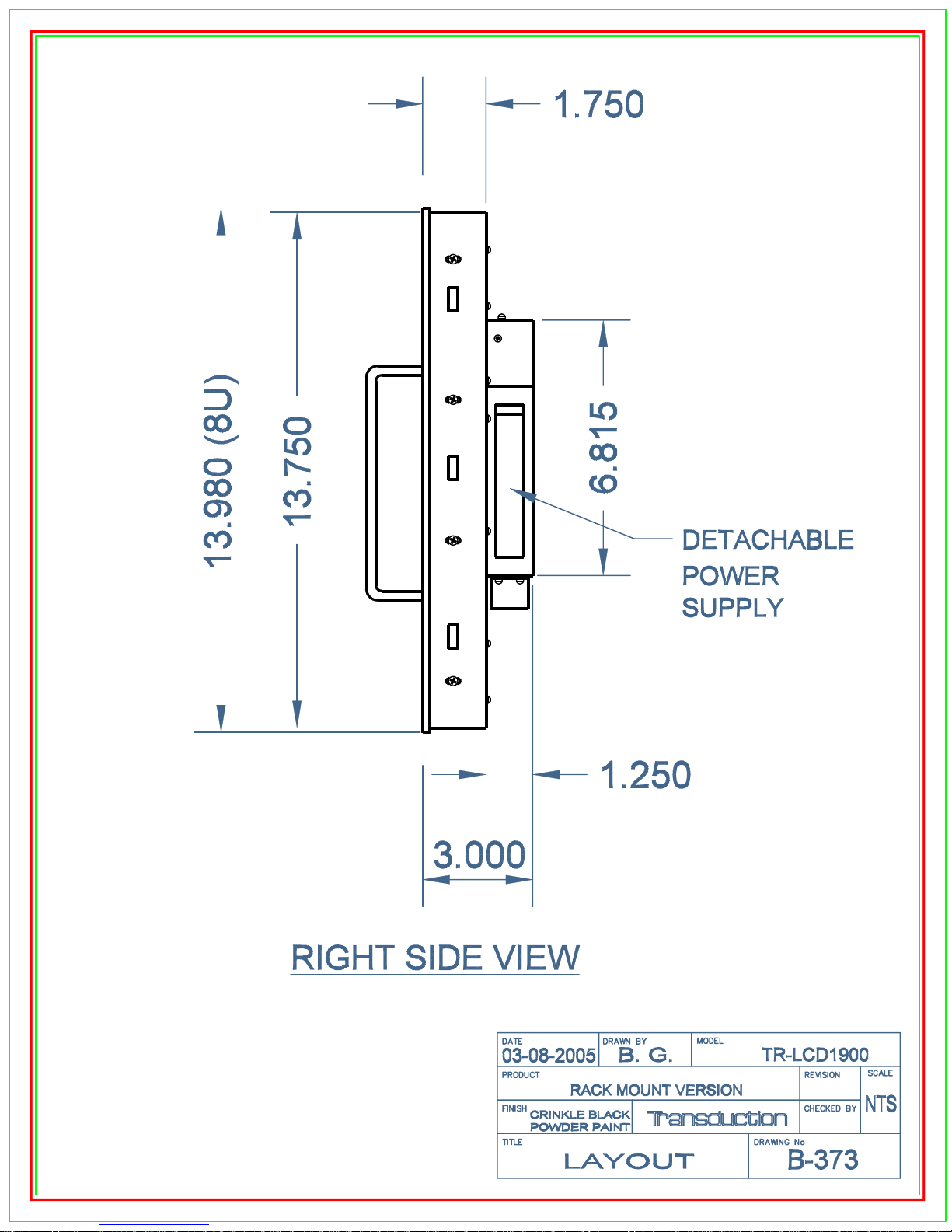
18.96” x 2.875” x 14” (8U) / 14.3 lb
48.16cm x 7.3cm x 35.56cm / 6.5 k g
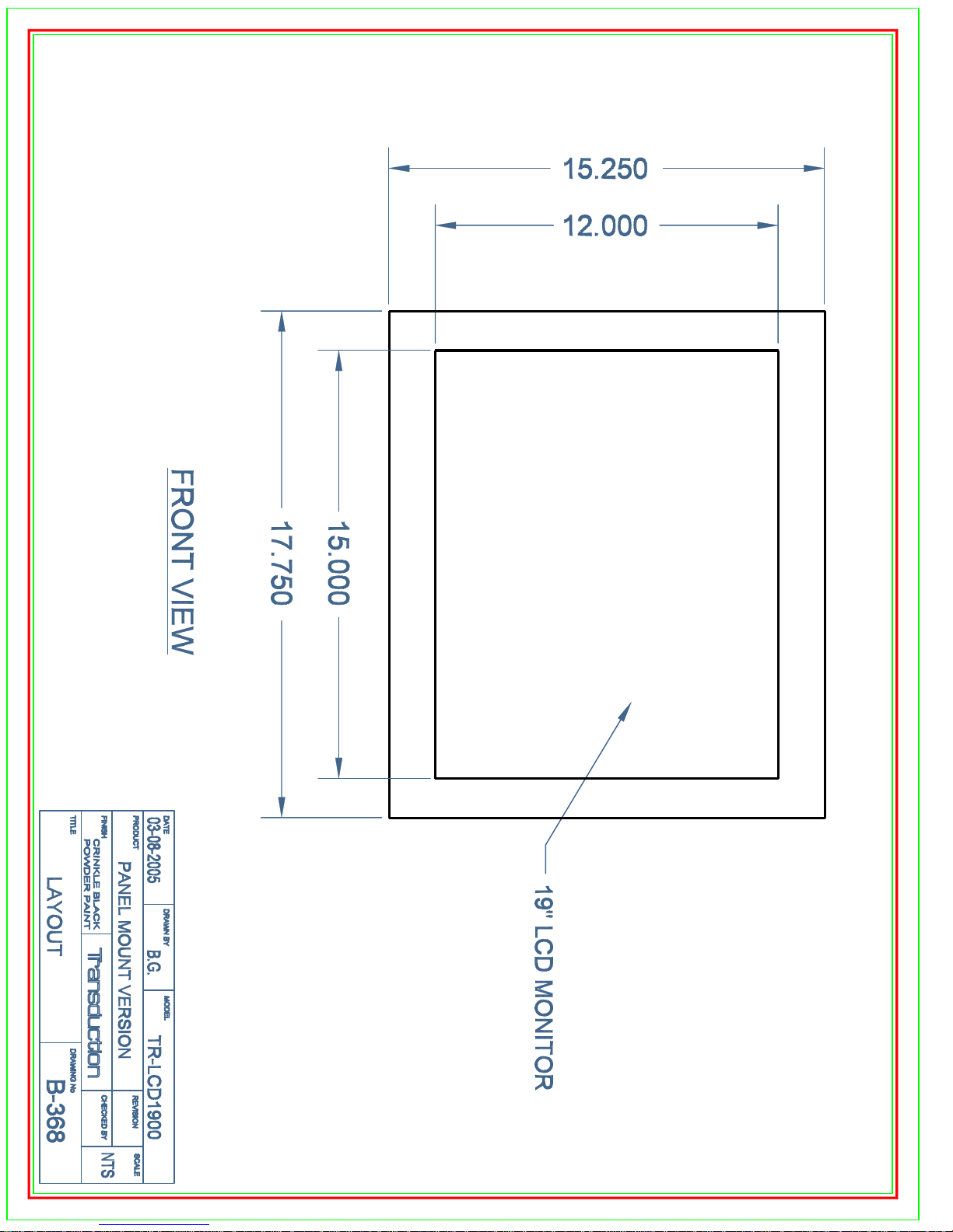
17.75” x 3.00” x 15.25” / 14 lb
45.09cm x 7.62cm x 38.74cm / 6.35 k g
32°F ~ 122°F (0°C ~ 50°C)
10% ~ 80%, non-condensing
-4°F ~ 140°F (-20°C ~ 60°C)
5% ~ 95%, non-condensing
Vibration & Shock 5G/30G
the monitor and computer systems will provide the best operating conditions and
monitor settings. In most cases, monitor installation will proceed autom atic ally,
unless the user wishes to select alternate settings.
precision of 99.999% above is used for this product. B ut the RED, G R E E N, B LUE
and WHITE c olor pixels may s eem to be bright sometimes or some black pixels
could be seen. This is normal.
2
Active matrix, thin film transistor
(TFT) liquid crystal display
(LCD)
Automatically
Automatically
Dependent on display card
used.
See Other Resolutions
Supported on page 32 for
complete list
For example, the no. of TFT LCD pixels that is contained in this product are
3,932,160.
For Windows 98SE or later.
FCC Class A
CE
UL
10 TR-LCD1900
Page 13
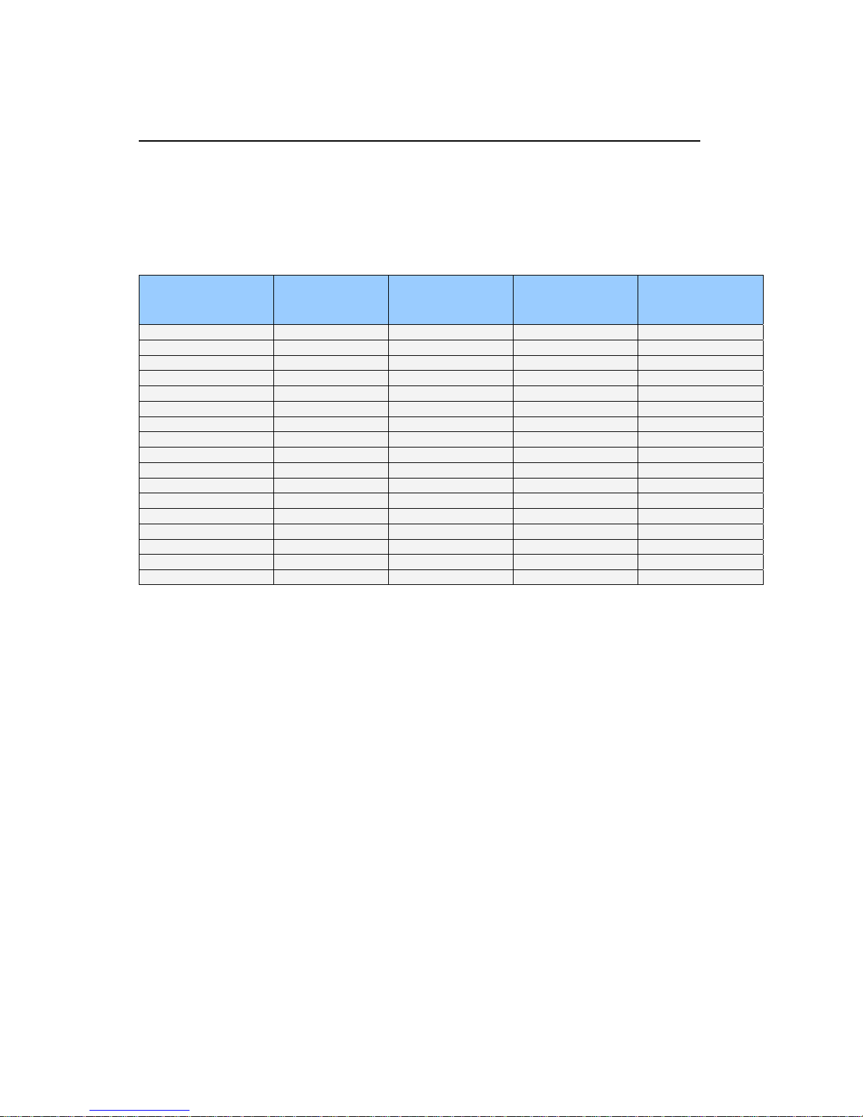
Resolutions Supported
Display Mode Horizontal
Vertical
Pixel Clock
Sync Polarity
If the signal transferred from the computer is the same as the following Preset Timing Modes, the
screen will be adjusted automatically. However, if the signal differs, the screen may go blank while
the power is on. Refer to the video card manual and adjust the screen as follows.
Preset Timing Modes
Frequency
(kHz)
IBM, 640 x 350 31.469 70.086 25.175 +/IBM, 640 x 480 31.469 59.940 25.175 -/IBM, 720 x 400 31.469 70.087 28.322 -/+
MAC, 640 x 480 35.000 66.667 30.240 -/MAC, 832 x 624 49.726 74.551 57.284 -/VESA, 640 x 480 37.500 75.000 31.500 -/VESA, 640 x 480 37.861 72.809 31.500 -/VESA, 800 x 600 35.156 56.250 36.000 +,-/+,VESA, 800 x 600 37.879 60.317 40.000 +/+
VESA, 800 x 600 46.875 75.000 49.500 +/+
VESA, 800 x 600 48.077 72.188 50.000 +/+
VESA, 1024 x 768 48.363 60.004 65.000 -/VESA, 1024 x 768 56.476 70.069 75.000 -/VESA, 1024 x 768 60.023 75.029 78.750 +/+
VESA, 1280 x 1024 63.981 60.020 108.00 +/+
VESA, 1280 x 1024 79.976 75.025 135.00 +/+
SUN, 1280 x 1024 81.129 76.106 135.00 -/-
Frequency
(Hz)
(MHz)
(H/V)
Horizontal Frequency
The time to scan one line connecting the right edge to the left edge of the screen horizontally is
called Horizontal Cycle and the inverse number of the Horizontal Cycle is called Horizontal
Frequency. Unit: kHz
Vertical Frequency
Like a fluorescent lamp, the screen has to repeat the same image many times per second to
display an image to the user. The frequency of this repetition is called Vertical Frequency or
Refresh Rate. Unit: Hz
11 TR-LCD1900
Page 14

TRANSDUCTION
5155 Spectrum Way Bldg 23
Mississauga, ON
L4W 5A1
Canada
905-625-1907
www .transduction.com
12 TR-LCD1900
Page 15
Page 16
Page 17
Page 18
Page 19
Page 20
Page 21
Page 22
Page 23
 Loading...