

Transduction TR-LCD1900-ITX-7 User Manual
TRANSDUCTION
USER’S MANUAL
TR-LCD1900-ITX-7 INDUSTRIAL PANEL/RACK
AND 19” LCD TOUCH SCREEN DISPLAY
5155 Spectrum Way, Mississauga, ON, Canada L4W 5A1
TEL: 1-800-268-0427, 905-625-1907
FAX: 905-625-0531
Email: sales@transduction.com

Table of Contents
Important Information ............................................................................. 4
Product Description & War
ranty ............................................................. 5
Chapter 1 - Introduction ........................................................................... 6
TR-LCD1900-ITX-7 Specifications...........................................................
7
LCD Display Opera
tion .......................................................................... 9
TR-LCD1900-ITX-7 SBC Features ..........................................................
10
TR-LCD190
0-ITX-7 SBC Specifications...............................
................... 11
Chapte
r 2 – TR-LC
D1ϵ00-ITX-
7 SBC Jumpers & Connec
tors .................. 14
Section 1 – Jumpers
on the TR-LCD1900-ITX-7 SBC ............................ 15
Ju
mper Location
s on the TR-LCD1900-ITX-7 SBC ............................ 16
JP
1, JP2: COM P
ower Selection ....................................................... 17
JP3: Clear CMOS RAM Data ............................................................. 17
JP4: CF Card Mode Selection .......................................................... 18
JP5: COM1 Power Pin (Pin9) ........................................................... 18
AT MODE: AT Mode Selection ........................................................ 18
LCDPWR: LCD PANEL Power Selection ............................................ 19
COM2MODE: RS232/RS422/RS485................................................. 19
Section 2 – Connectors on the TR-LCD1900-ITX-7 .............................. 20
Co
nnect
or L
ocati
ons on the TR-LCD1900-ITX-7 .............................. 21
Fr
ont Panel Co
nnector .................................................................... 22
BACKLIGHT Connector .................................................................... 23
IRDA Connector ............................................................................... 23
IDE Connectors ................................................................................ 24
COM1 Serial Port ............................................................................. 25
TR-LCD1900-ITX-7 User Manual
1

Table of Contents
Section 2 – Connectors on the TR-LC
D1900-ITX-7 (Cont’d)
COM2 Serial Port ............................................................................. 25
COM3, COM4, COM5, COM6 Serial Ports ....................................... 26
PWROUT1 Connector ...................................................................... 26
PWROUT2 Connector ...................................................................... 26
LPT Port ........................................................................................... 27
PS/2 Keyboard & Mouse Connector ............................................... 28
PS2KBMS Connector ....................................................................... 28
VGA Connector ............................................................................... 29
VGA1 Connector ............................................................................. 29
VGA2 Connector ............................................................................. 30
DCIN Connector .............................................................................. 30
DCIN2 Power Connector ................................................................. 31
CPU Fan Power Connector .............................................................. 31
FAN1 Power Connector ................................................................... 31
FAN2 Power Connector ................................................................... 31
USB12 USB34 Connectors ............................................................... 32
LANGbE+USBx2 Connectors ............................................................ 32
LAN-GBE Connectors ....................................................................... 33
LAN RJ45 LED1, 2 ............................................................................. 33
Audio Connectors............................................................................ 34
Audio 1 Pin Headers ........................................................................ 34
Audio 2 Pin Headers ........................................................................ 34
SATA1, SATA2, SATA3 Connectors .................................................. 35
TR-LCD1900-ITX-7 User Manual
2

Table of Contents
Section 2 – Connectors o
n the TR-LCD1900-ITX-7 (Cont’d)
DIO Pin Header ................................................................................ 35
LVDS Connector .............................................................................. 36
CF-II Connector ............................................................................... 37
Chapter 3 – BIOS Setup .......................................................................... 37
Main Menu .......................................................................................... 43
Standard CMOS Features .................................................................... 46
Advanced BIOS Features ..................................................................... 51
Advanced Chipset Features ................................................................. 56
Integrated Peripherals ........................................................................ 59
Power Management Setup ................................................................. 71
PnP/PCI Configuration ......................................................................... 73
PC Health Status .................................................................................. 77
Load Fail-Safe Defaults ........................................................................ 79
Load Optimized Defaults ..................................................................... 79
Set Supervisor/User Password ............................................................ 80
Save & Exit Setup ................................................................................ 82
Exit Without Saving ............................................................................. 82
Chapter 4 – Appendix ............................................................................. 83
AC Power Adapter ........................................................................... 84
I/O Port Address Map ..................................................................... 85
Interrupt Request Lines (IRQ) ......................................................... 86
POST Beep ....................................................................................... 87
Resistive Touch Screen Option ....................................................... 88
TR-LCD1900-ITX-7 Mechanical Drawings ........................................ 95
TR-LCD1900-ITX-7 User Manual
3

Important Information
The information in this document is subject to change without notice.
All relevant issues have been considered in the preparation of this document. Should you notice an
omission or any questionable item in this document, please feel free to notify Transduction.
Regardless of the foregoing statement, Transduction assumes no responsibility for any errors that may
appear in this document nor for results obtained by the user as a result of using this product.
Copyright © 2015 Transduction. All rights reserved.
This document is protected by copyright. No part of this document may be reproduced, copied or
translated in any form or means without prior written permission from Transduction.
All other trademarks, brand and product names are the property of their respective owners.
Return policy
Warranty is 3 years for the whole system from the date of purchase. Products returned for repair must be
accompanied by a Return Material Authorization (RMA) number, obtained from Transduction prior to return.
Freight on all returned items must be prepaid by the customer. The customer is responsible for any loss or
damage caused by the carrier in transit.
To obtain an RMA number, call us at 905-625-1907. We will need the following information:
· Return company address and contract
· Model name, model number and serial number
· Description of the failure
Mark the RMA number clearly on the outside of each box, include a failure report and return the product
to:
Transduction
5155 – 23 Spectrum Way
Mississauga ON Canada L4W 5A1
Attn: RMA Department
TR-LCD1900-ITX-7 User Manual
4

Product Description
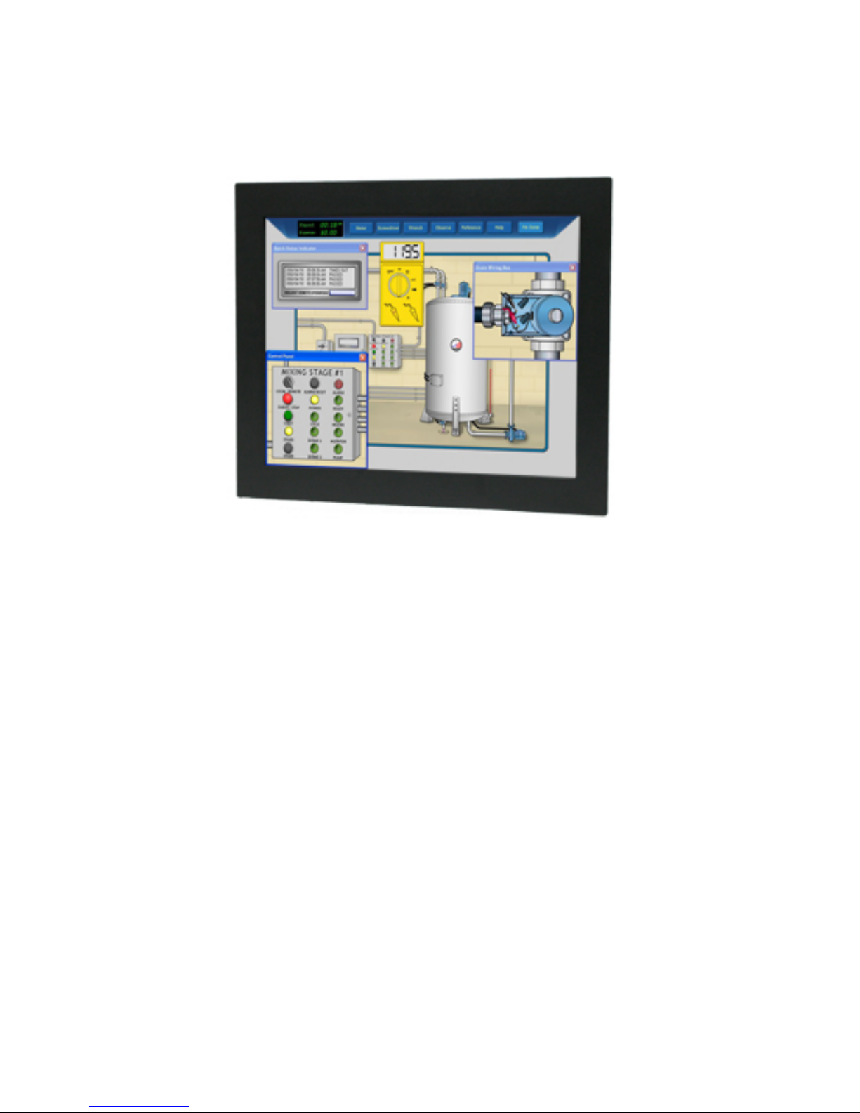
TR-LCD1900-ITX-7 is a NEMA 4 Panel/Rack
Mount Industrial Computer.
TR-LCD1900-ITX-7 industrial computer with or without touch screen has
been
designed
to provide many years
of reliable operation in industrial
environments. The warranty is 3 years but MTBF based on serivice
records is in excess of 100,000 hours.
Based on the Intel Dual ATOM 1.8GHz processor, TR-LCD1900-ITX-7 provides
a low cost
alternative to comparable products offered by our competitors costing
3 times more.
Designed by Transduction this computer is ma
nufactured in Canada with
the same high quality standards that we use for military and nuclear clients.
Warranty
Warranty is unconditional for 3 years from the date of Transduction invoice,
FOB our plant in Mississauga. Transduction Return Material Authorization
(RMA) number must be obtained prior to return of any goods for service and
clearly shown on the shipping label. For RMA number call 905-625-1907
ext. 12, 9AM to 5PM Eastern Time Zone.
TR-LCD1900-ITX-7 User Manual
5

1
Introduction
This manual is designed to give you information on the
TR-LCD1900-ITX-7 industrial PC.The topics covered in this
chapter are as follows:
TR-LCD1900-ITX-7 Specifications ............................. 7-8
LCD Display Operation ............................................... 9
TR-LCD1900-ITX-7 SBC Features ............................... 10
TR-LCD1900-ITX-7 SBC Specifications ................
.... 11-13
6
TR-LCD1900-ITX-7 User Manual

TR-LCD1900-ITX-7 Specifications
Model TR-LCD1900-ITX-7 Industrial
Panel/Rack Computer
Processor 1.8GHz Intel Atom D525 with four
threads
Cooling 3 x cooling fans with speed control
One CPU cooler and two for system fans
Chipset
Intel ICH8M 64-Bit
BIOS Award PnP Ver. 6.0
8Mbit FlashROM with BootBlock for failsafe
Display 19” TFT LCD, resolution 1280 x 1024
(SXGA)
Backlight MTBF > 150,000 hours
Brightness - 350cd/m², Contrast ratio 700:1 (brightness and contrast software
adjustable)
USB resistive touch screen
Memory Up to 4GB SO-DIMM DDR3 800MHz
Display Intel D525 integrated GMA3150 Graphic
Engine Interface
DB15 SVGA connector
Dual VGA display supported - display
devices can be selected by BIOS or
graphics drivers
Ethernet 2 x Realtek RT8111E Gigabit LAN
External RJ45 connectors
PXE Boot ROM and WOL supported
Green Function Power saving mode includes doze,
standby and suspend modes
External I/O 1 x SVGA DB15 - mirror of LCD
2 x serial ports
1 x parallel port
4 x USB 2.0 ports
2 x audio jacks
Disk I/O Optional SLIM CD-R/W-DVD
One or two 2.5” SATA hard drives 500
or 1000GB
Optional high speed ash 64GB ~ 256GB
with S.M.A.R.T. and SUPERCAP features
Optional RAID1
Green Function Power saving mode includes doze,
standby and suspend modes
Audio Realtek ALC888 high denition
7.1 channel surrounding audio support
Watchdog Timer System reset programmable watchdog
timer with 1 ~ 255sec time-out value
Operating Temperature 0 ~ 50ºC (32º ~ 122ºF) with hard drive
0 ~ 60ºC (32º ~ 140ºF) for 2 hours with
SSD
Storage Temperature -20 ~ 85ºC (-4º ~ 185ºF)
Humidity Relative humidity 10 ~ 90%,
non-condensing
Storage: Relative humidity 45% max.
non-condensing
TR-LCD1900-ITX-7 User Manual 7
TR-LCD1900-ITX-7 Specifications
Shock and Vibration Shock - 25G, Vibration - 5G
Power Requirement DC 12V input with 4-pins Mini-DIN
connector
Includes universal AC 12VDC 100W
power adapter
Optional DC input 12, 24, 48, 125 and
250V
Compliance: Electrical Safety
Approval, CE and FCC Class B
Compatible with Windows 10 32/64-
bit, Windows 7 32/64-bit, Windows
Vista, Windows XP, Windows 2000,
QNX, LINUX and DOS 6.22
Warranty 3 years
Dimensions Panel mount version - 3.943” (4.625”
with CD/DVD) (H) x 15.250” (D) x
17.750” (W)
Rack mount version - 3.943” (4.625”
with CD/DVD) (H) x 13.980” (D) x
18.960” (W)
Weight
10.5kg (23.15lbs)
TR-LCD1900-ITX-7 User Manual 8

1. LCD Monitor screen is always connected via internal LVDS
interface. It can be disabled in the BIOS set-up.
2. External analog SVGA port is the "mirror" of the LCD screen
for connection of the external monitor.
3. LCD display settings can be changed in SET-UP section of the
video driver.
4. For touch screen installation and calibration is "Resistive Touch
Screen Option" section in the appendix of the manual.
LCD Display Operation
TR-LCD1900-ITX-7 User Manual 9

Features
Intel Dual Core Atom Processor D525 on board.
Dual GbE LAN, Dual DDR3 socket for up to 4GB.
Compact size design with rich I/O functions.
Multiple I/O functions: 8 x USB2.0, 6 x COM, 3 x
SATA, 1 x IRDA, 1x PIDE, 1x CF, 1x LPT, 1x DIO.
Multiple display devices: VGA1, VGA2, HDM, Single
Channel 24-bits LVDS LCDI.
Single DC +12V input power for normal operation.
Dual Mini Card Socket and one PCI 32-bits slot for
flexible I/O expansion.
7.1 channels surrounding audio support.
10
TR-LCD1900-ITX-7 User Manual

Specifications
Processor
Intel Dual Core Atom D525 processor on board.
1.8GHz Core Speed with dual Core and four Threads.
BIOS
Award Standard PnP Flash BIOS 6.0.
8Mbit FlashROM with BootBlock for fail-safe.
System Memory
Two DDR3 SO-DIMM Sockets.
Supports DDR3-800 non-ECC memory up to 4.0 GB.
Chipset
Intel ICH8M chipset.
Video
Intel D525 Integrated GMA3150 graphic engine.
One D-Sub female connector for CRT displays.
One 40-pins connector for single 24-bits LVDS LCD.
One HDMI for HD 1080p displays.
Dual VGA display supported.
Support dual Independent display, display devices can
be selectable by BIOS or graphic drivers.
10/100M/1000M Ethernet
Two Realtek RT8111E on board for Dual Gigabit LAN
support.
PXE Boot ROM and WOL supported.
On Board I/O
Six serial ports as COM1~COM6. COM2 is
RS232/422/485 selectable by jumper.
COM1 and COM2 are D-Sub on rear panel. Pin9 is
powered with either +5V or +12V by jumper.
11
TR-LCD1900-ITX-7 User Manual

COM3~COM6 are pin-header for internal connections.
One parallel port supports SPP/ECP/EPP mode.
1 x IrDA port. 1x DIO (8-bits).
Dual Mini PCI-Express sockets.
One PCI 32-bits slot, supports up to 3 master devices.
Eight USB 2.0 ports. Four on real panel and four for
internal connections.
PIDE and SATA
PIDE controller built in ICH8M support up to UltraDMA
mode 5 or ATA100 speed.
One standard 44-pins box header to supports 2.5” HDD
or DOM Flash Disk.
Three SATA ports from ICH8M support up to SATA-II
devices.
One 50-pins CF-II socket for Compact Flash Card.
Watchdog Timer
Programmable watchdog timer for 1~255 seconds.
CMOS
On-board RTC with 242 bytes of Battery-back CMOS
RAM.
Audio
RealTek ALC888 High-Definition Audio chip on-board.
Two Audio-Jacks on rear for Audio Line-out and MIC.
7.1 channel surrounding audio supported.
Power
Single DC 12V input with 4-pins Mini-DIN connector.
Supplies +5V and +12V output power for peripheral
devices and LCD panel.
12
TR-LCD1900-ITX-7 User Manual

Software Compatibility
Microsoft windows: Win10 32/64bits, Win7 32/64bits,
Win XP 32/64bits, XP embedded standard, WinCE 6.0.
Linux 32/64bits and DOS 6.22.
Cooling
Three cooling FAN connectors.
One for CPU cooler and two for System FAN.
Dimensions
190mm (W) x 135mm (L).
4 screw holes on four corners.
Operating Temperature
0 to 60 C operating Range.
Relative Humility: 5~95%, non-condensing.
13
TR-LCD1900-ITX-7 User Manual

2
14
TR-LCD1900-ITX-7 User Manual
Jumper Settings & Connectors
This chapter provides information on the TR-LCD1900-ITX-7
jumper settings and internal and external connectors. The
topics covered are as follows:
Section 1 - Jumpers on the TR-LCD1900-ITX-7 ............ 16-19
Section 2 - Connectors on the TR-LCD1900-ITX-7 ........ 20-37

2 Section 1
15
TR-LCD1900-ITX-7 User Manual
Jumpers on the TR-LCD1900-ITX-7 SBC
The jumpers on the TR-LCD1900-ITX-7 SBC allow you to configure
your board according to the needs of your applications. The
following table lists the jumpers on TR-LCD1900-ITX-7 SBC and
their respective functions.
Jumper Locations on the TR-LCD1900-ITX-7 SBC ........... 16
JP1, JP2: COM Power Selection ..................................... 17
JP3: Clear CMOS RAM Data .......................................... 17
JP4: CF Card Mode Selection ........................................ 18
JP5: COM1 Power Pin (Pin9) ......................................... 18
AT MODE: AT Mode Selection ....................................... 18
LCDPWR: LCD PANEL Power Selection ........................... 19
COM2MODE: RS232/RS422/RS485 ............................... 19
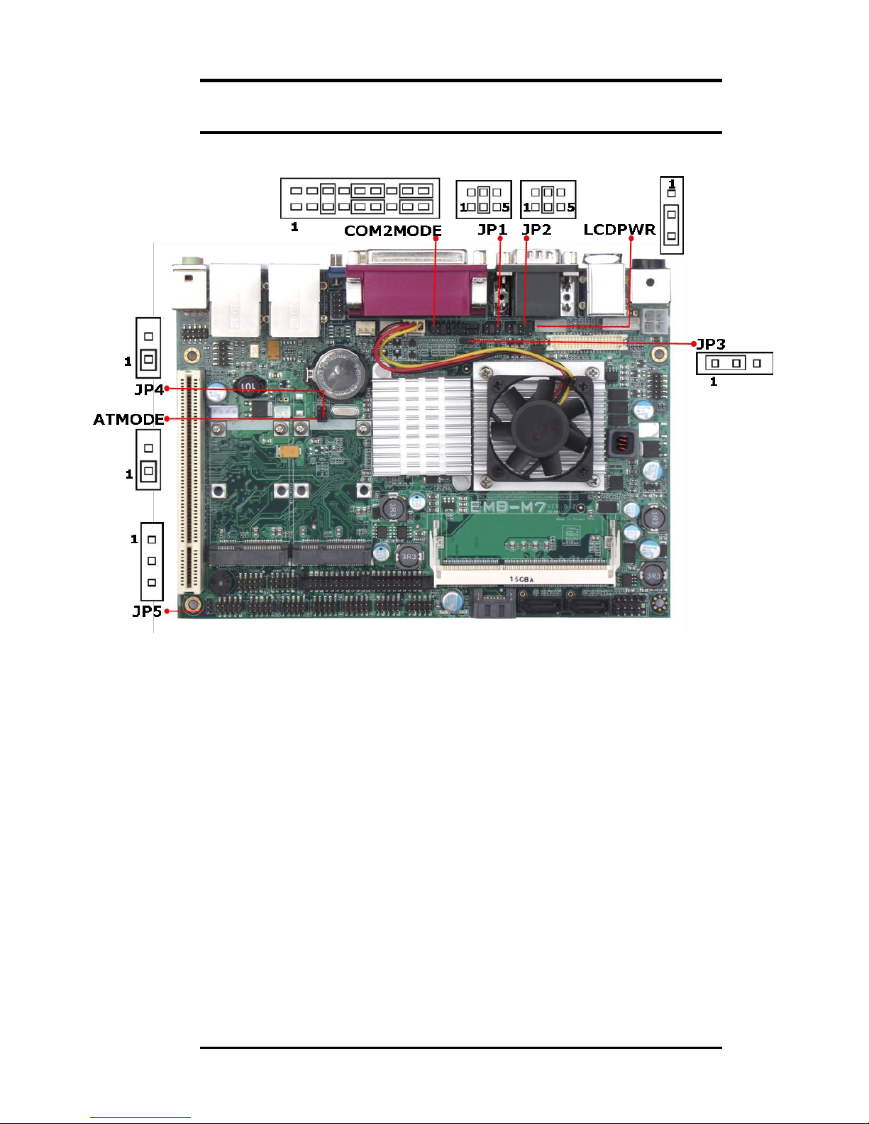
Jumper Locations on the TR-LCD1900-ITX-7
16
TR-LCD1900-ITX-7 User Manual
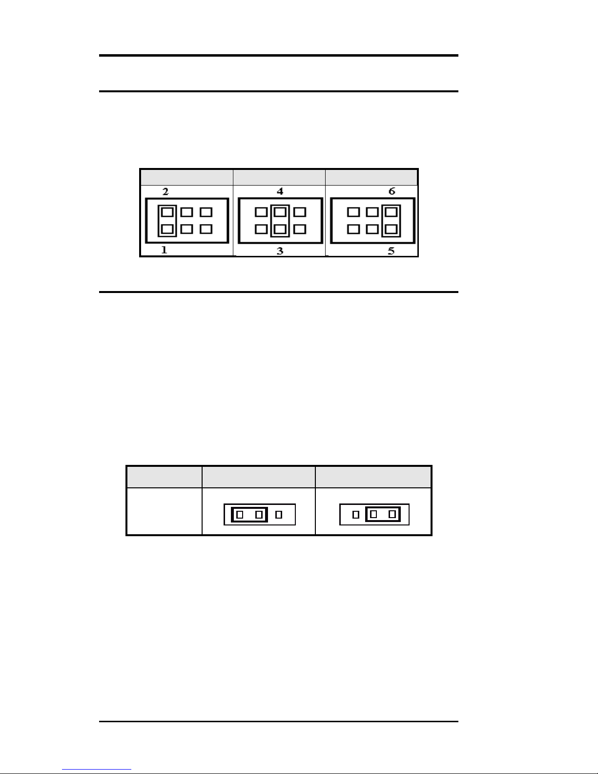
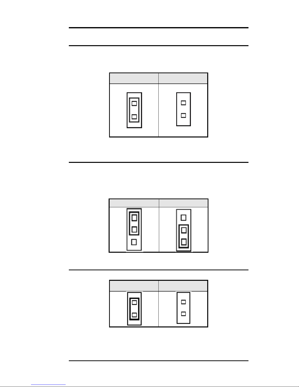
JP1, JP2: COM Power Selection
JP1, JP2 can be used to select the COM supple power:
+5V, Ring-IN or +12V.
JP1: COM2Pin9 power or Ring-IN
JP2: COM1 pin9 power or Ring-IN
+5V
RI
+12V
JP3: Clear CMOS RAM Data
This 3-pin Jumper allows the user to disconnect the
built-in 3V battery power to clear the information stored
in the CMOS RAM. To clear the CMOS data:
1. Turn off the system power.
2. Remove Jumper cap from pin1&2.
3. Short the pin2 and pin3 for three seconds.
4. Put Jumper cap back to pin1 & 2.
5. Turn on your computer.
6. Hold Down <Delete> during boot up and enter BIOS
setup to enter your preferences.
COMS
NORM
CLR
JP3
1-2 2-3
17
TR-LCD1900-ITX-7 User Manual
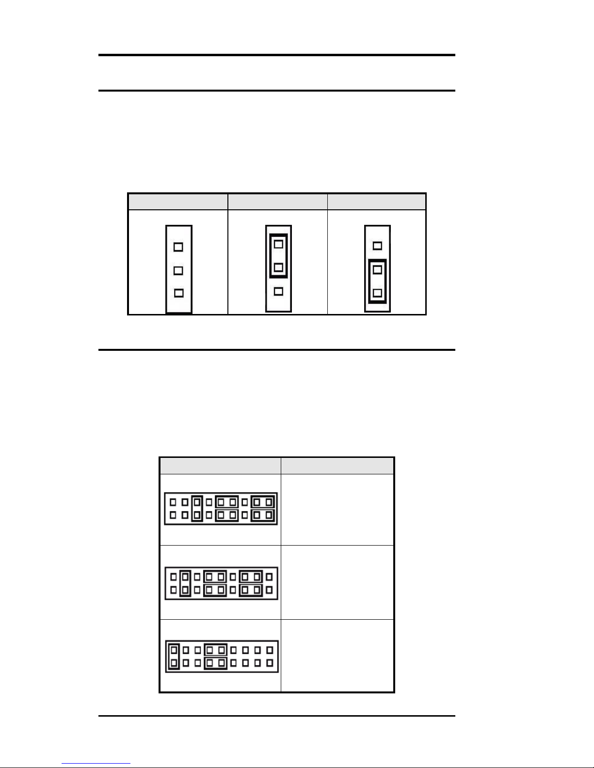
JP4: CF Card Mode Selection
This Jumper is to select the CF works as Secondary
Channel Master Device or Slave Device.
Master
Slave
JP4
JP4
JP5: COM1 Power Pin (Pin9)
JP5 can be used to select the COM supple power: +5V or
+12V.
JP5: COM6 Pin9 power
+5V
+12V
AT MODE: AT Mode Selection
AT Mode
ATX Mode
1
1
1
1
18
TR-LCD1900-ITX-7 User Manual
LCDPWR: LCD PANEL Power Selection
LCDPWR can be used to select the Panel LCD supple
power: +3.3V or +5V.The default setting is on
+3.3V.User need to check the LCD panel spec and adjust
this jumper to make Panel work in specified power rail.
This Jumper serves LVDS LCD connector.
LCDPWR
+5V
+3.3V
1 1 1
COM2MODE: RS232/RS422/RS485
COM2 support multi-protocols include RS232, RS422
and RS485, while COM3, COM4. COM5 and COM6
support diffused RS232 protocol.
The Protocols of COM2 can be set up through jumpers.
COM2MODE: COM2 Protocols selection.
The pin-out for each mode is illustrated on next chapter.
COM2MODE1
I/F TYPE
2 18
1 17
RS-232
2 18
1 17
RS-422
2 18
1 17
RS-485
19
TR-LCD1900-ITX-7 User Manual

Connector Locations on the TR-LCD1900-ITX-7 .......... 21
Front Panel Connector ............................................. 22
BACKLIGHT Connector ............................................ 23
IRDA Connector ..................................................... 23
IDE Connectors ...................................................... 24
COM1 Serial Port .................................................... 25
COM2 Serial Port .................................................... 25
COM3, COM4, COM5,COM6 Serial Ports ..................... 26
PWROUT1 Connector .............................................. 26
PWROUT2 Connector .............................................. 26
LPT Port ................................................................ 27
PS/2 Keyboard & Mouse Connector ........................... 28
PS2KBMS Connector ............................................... 28
VGA Connector ...................................................... 29
VGA1 Connector ..................................................... 29
VGA2 Connector ..................................................... 30
DCIN Connector ..................................................... 30
DCIN2 Power Connector .......................................... 31
CPU Fan Power Connector ....................................... 31
FAN1 Power Connector ............................................ 31
FAN2 Power Connector ............................................ 31
USB12 USB34 Connectors ....................................... 32
LANGbE+USBx2 Connectors .................................... 32
LAN- GBE Connectors ............................................. 33
LAN RJ45 LED1, 2 .................................................. 33
Audio Connectors ................................................... 34
Audio1Pin Headers ................................................. 34
Audio 2 Pin Headers ............................................... 34
SATA1, SATA2, SATA3 Connectors ........................... 35
DIO Pin Header ...................................................... 35
LVDS Connector ..................................................... 36
CF-II Connector ..................................................... 37
2 Section 2
Connectors on the TR-LCD1900-ITX-7
The connector on the TR-LCD1900-ITX-7 allows you to connect
external devices such as keyboard, floppy disk drives, hard
disk drives, printers and etc. The following table lists the
connectors on TR-LCD1900-ITX-7 and their respective page
number.
20
TR-LCD1900-ITX-7 User Manual
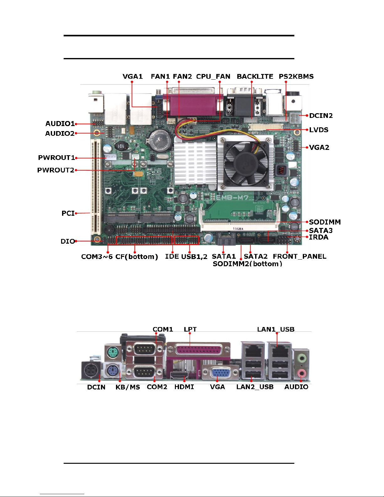
Connector Locations on the TR-LCD1900-ITX-7
21
TR-LCD1900-ITX-7 User Manual
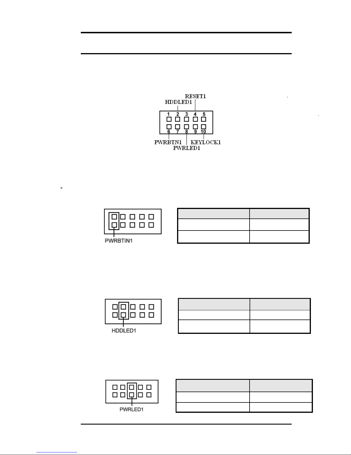
Front Panel Connector
The front panel of the case has a control panel, which
provides light indication of the computer activities and
switches to change the computer status.
ATX Power ON/OFF Button
This 2-pin connector acts as the “Power Supply On/Off
Switch” on the TR-LCD1900-ITX-7 main board. When
pressed the,
switch will force the Main board to power on.
When pressed again, it will force the main board to power off.
PWR BTN Pin # Signal Name
1
PWR-BTN
6
GND
HDD LED Connector
This connector connects to the hard drive activity LED on
control panel. This LED will flash when the HDD is being
accessed.
HDD LED Pin #
Signal Name
2
VCC
7
HDDLED
Power-On LED
This connector allows users to connect to Front Panel
Power indicator.
Power-On Pin #
Signal Name
3
VCC
8
GND
22
TR-LCD1900-ITX-7 User Manual
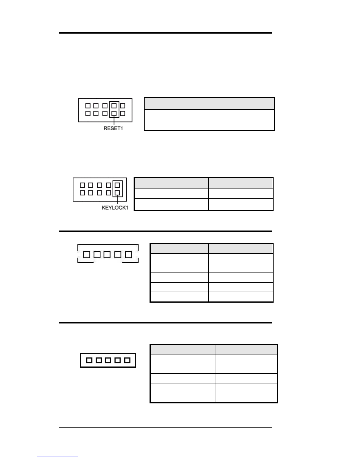
RESET Switch
The reset switch allows the user to reset the system
without turning the main power switch off and then on.
Orientation is not required when making a connection to
this header.
RESET Pin #
Signal Name
4
Reset
9
GND
KEYLOCK Switch
The keylock switch, when closed, will disable the
keyboard function.
KEYLOCK Pin #
Signal Name
5
KEYLOCK
10
GND
BACKLIGHT Connector
1
Pin #
Signal Name
1
+12V
2
GND
3
Brightness
4
ON/OFF
5
GND
IRDA Connector
This connector is used for an IRDA connector for wireless
communication.
1
IrDA Pin #
Signal Name
1
+5V
2
FIR
3
IR-TX
4
GND
5
IR-RX
23
TR-LCD1900-ITX-7 User Manual
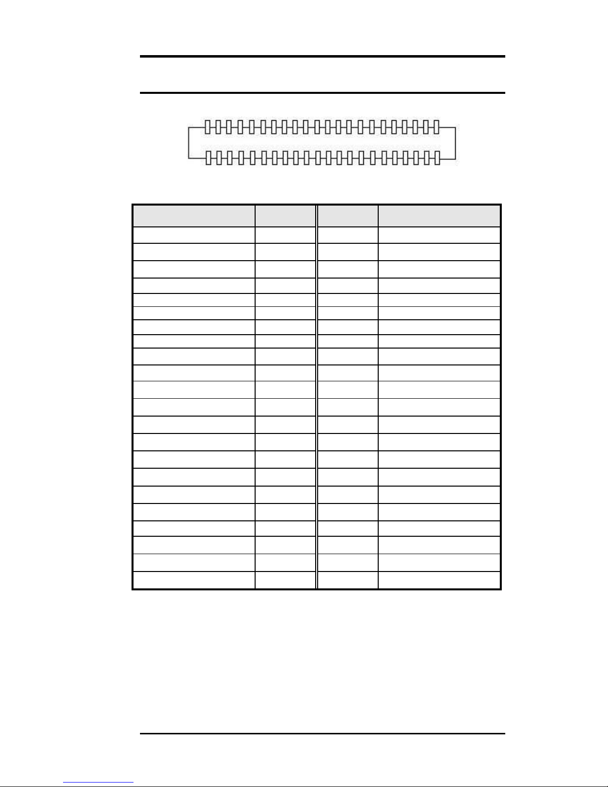
IDE Connectors
43 1
44 2
Primary IDE Connector
Signal Name
Pin #
Pin #
Signal Name
Reset IDE
1 2 Ground
Host data 7
3 4 Host data 8
Host data 6
5 6 Host data 9
Host data 5
7 8 Host data 10
Host data 4
9
10
Host data 11
Host data 3
11
12
Host data 12
Host data 2
13
14
Host data 13
Host data 1
15
16
Host data 14
Host data 0
17
18
Host data 15
Ground
19
20
Key
DRQ
21
22
Ground
Host IOW
23
24
Ground
Host IOR
25
26
Ground
IOCHRDY
27
28
Host PU 0
DACK
29
30
Ground
IRQ14
31
32
No connect
Address 1
33
34
P66DET
Address 0
35
36
Address 2
Chip select 1
37
38
Chip select 3
Activity LED
39
40
GND
VCC
41
42
VCC
GND
43
44
NC
24
TR-LCD1900-ITX-7 User Manual
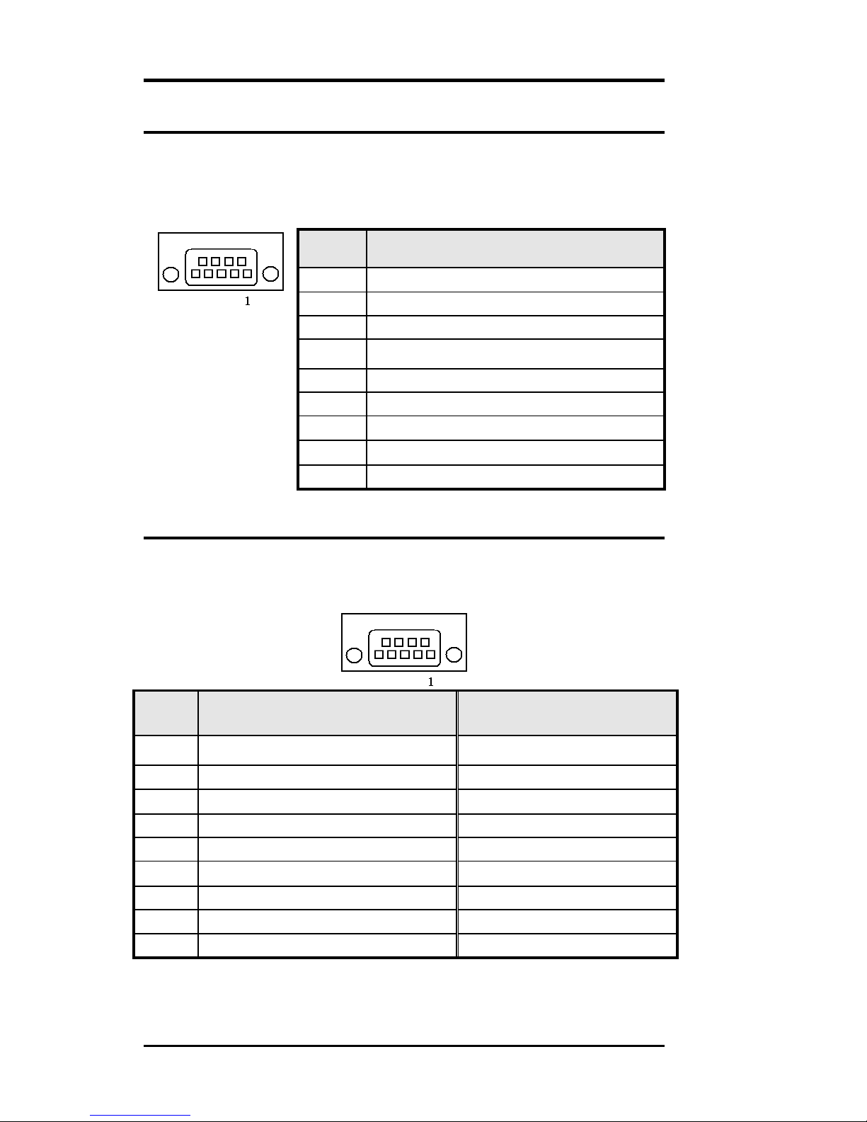
COM1 Serial Port
COM1, a 9-pin D-Sub male connector, is the onboard
COM1 serial port of the TR-LCD1900-ITX-7. The following table
shows its pin assignments.
Pin #
Signal Name
1
DCD, Data carrier detect
2
RXD, Receive data
3
TXD, Transmit data
4
DTR, Data terminal ready
5
GND, ground
6
DSR, Data set ready
7
RTS, Request to send
8
CTS, Clear to send
9
+5V,Ring-IN or +12V
COM2 Serial Port
COM2, a 9-pin D-Sub male connector, is the onboard
COM2 serial port of the TR-LCD1900-ITX-7. The following table
shows its pin assignments.
Pin #
RS232 Mode
Signal Name
RS422/RS485 Mode
Signal Name
1
DCD, Data carrier detect
TX- (422/485)
2
RXD, Receive data
TX+ (422/485)
3
TXD, Transmit data
RX+ (422)
4
DTR, Data terminal ready
RX- (422)
5
GND, ground
GND
6
DSR, Data set ready
N.C.
7
RTS, Request to send
N.C.
8
CTS, Clear to send
N.C.
9
+5V,Ring-IN or +12V
N.C.
25
TR-LCD1900-ITX-7 User Manual

COM3, COM4, COM5,COM6 Serial Ports
COM3, COM4, COM5, COM6 a 10-pin header connector,
is the onboard COM3, COM4, COM5, COM6 serial port of
the TR-LCD1900-ITX-7. The following table shows its pin
assignments.
Pin #
RS232 Mode Signal Name
1
DCD, Data carrier detect
2
RXD, Receive data
3
TXD, Transmit data
4
DTR, Data terminal ready
5
GND, ground
6
DSR, Data set ready
7
RTS, Request to send
8
CTS, Clear to send
9
Ring-IN
10
NC
PWROUT1 Connector
Pin #
Signal Name
1
VCC
2
GND
3
GND
4
+12V
PWROUT2 Connector
Pin #
Signal Name
1
VCC
2
GND
1
1
1 2 9
10
26
TR-LCD1900-ITX-7 User Manual
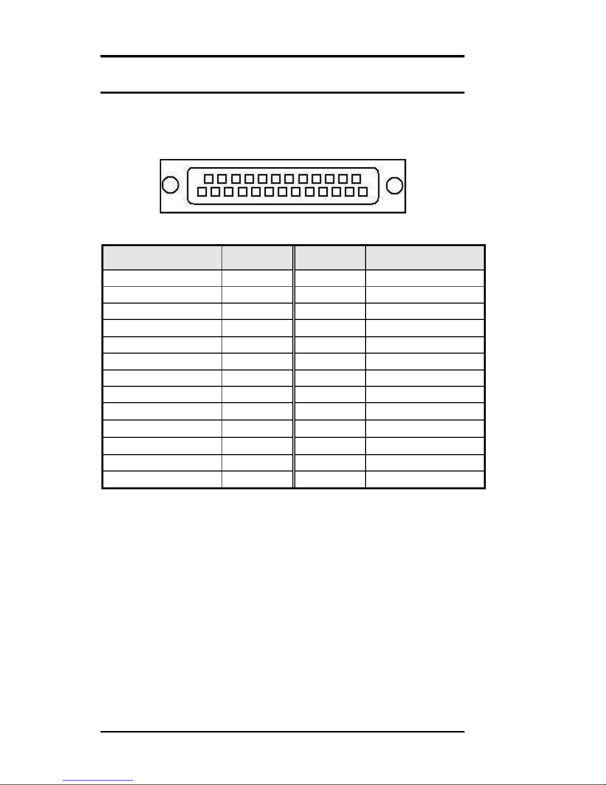
LPT Port
The LPT parallel port is a standard DSUB 25-pins Female
connector. It can be configured as EPP or ECP or SPP
mode.
Signal Name
Pin #
Pin #
Signal Name
Strobe
1
14
AUTOFD
DATA0
2
15
ERROR
DATA1
3
16
INIT
DATA2
4
17
SLIN
DATA3
5
18
GND
DATA4
6
19
GND
DATA5
7
20
GND
DATA6
8
21
GND
DATA7
9
22
GND
ACK
10
23
GND
BUSY
11
24
GND
PE
12
25
GND
SLCT
13
1
13
14
25
27
TR-LCD1900-ITX-7 User Manual
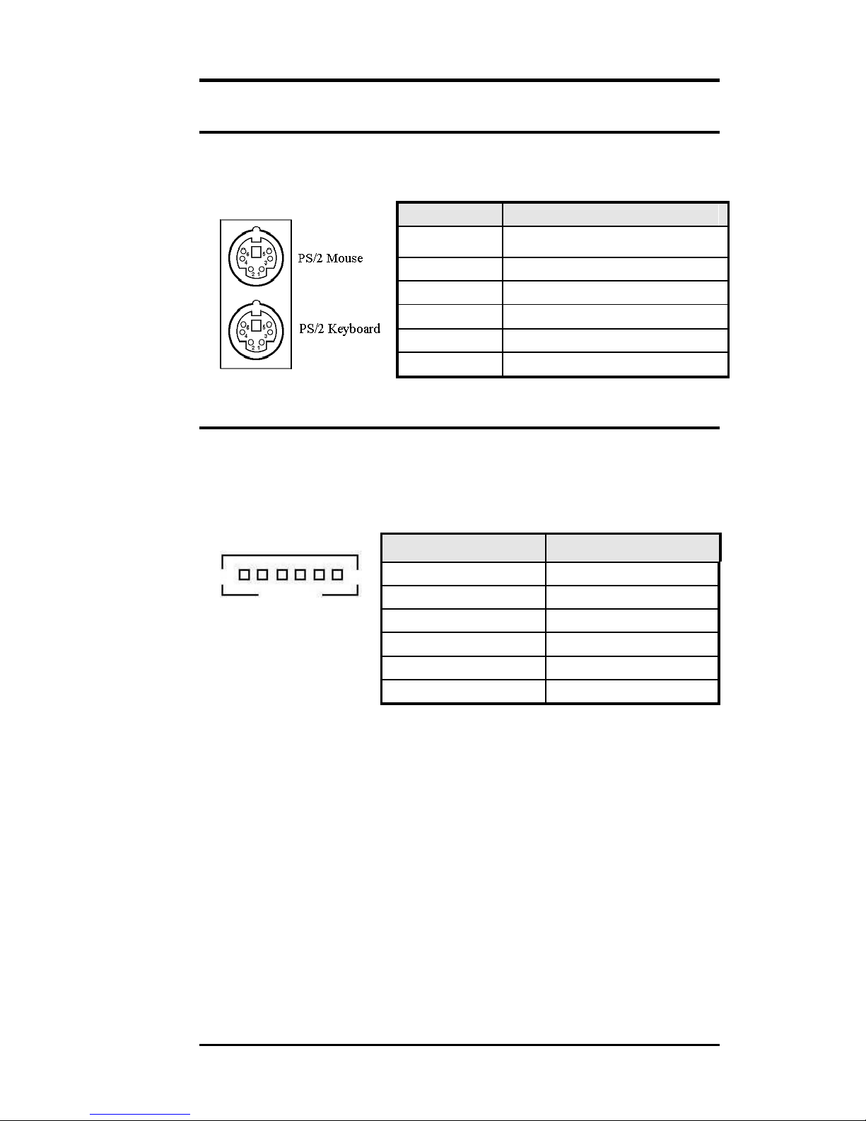
PS/2 Keyboard & Mouse Connector
The following table describes the pin assignment of PS/2
Keyboard and Mouse connector.
Pin #
Signal Name
1
Keyboard/Mouse data
2
NC
3
GND
4
5V
5
Keyboard/Mouse clock
6
GND
PS2KBMS Connector
The following table describes the pin assignment of PS/2
Keyboard and Mouse connector with 6-pins wafer for
internal or external access.
Pin #
Signal Name
1
RKBCLK
2
RKBDAT
3
RMSCLK
4
RMSDAT
5
RKBVCC
6
KBGND
1
28
TR-LCD1900-ITX-7 User Manual
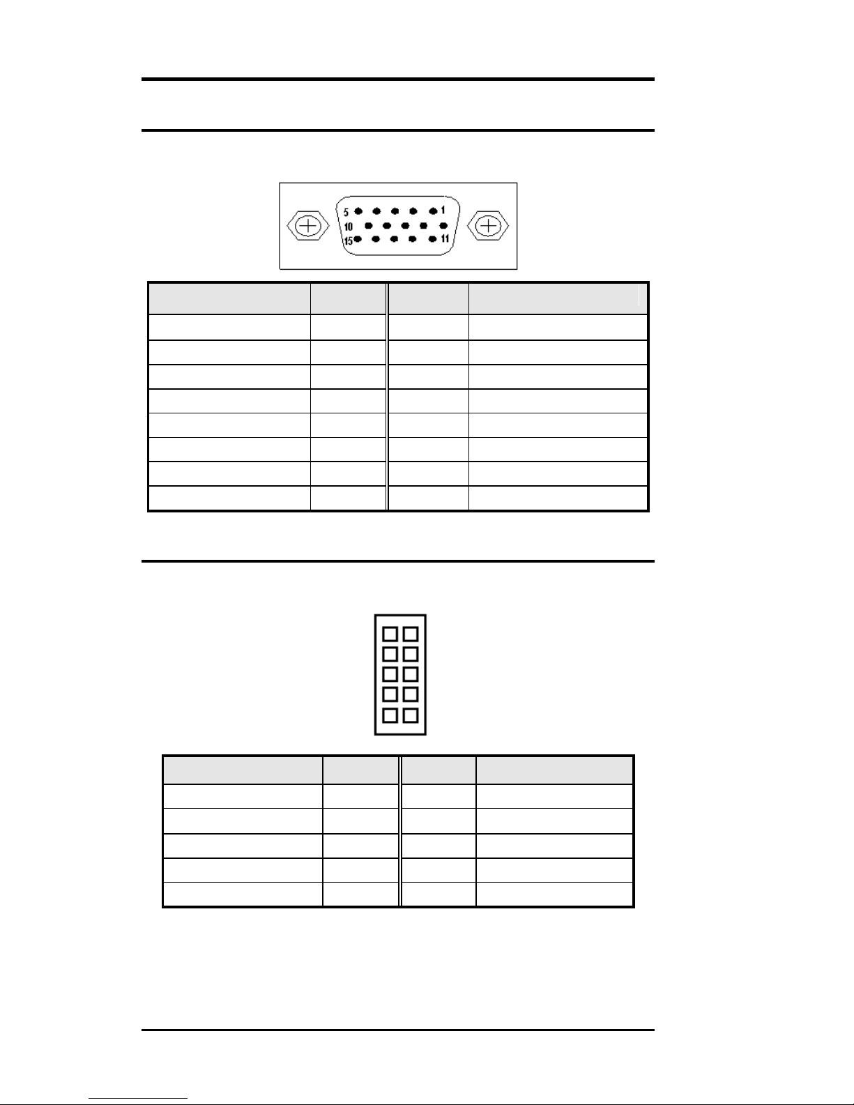
VGA Connector
The pin assignments of VGA CRT connector are as
follows:
Signal Name
Pin #
Pin #
Signal Name
Red
1 2 Green
Blue
3 4 N.C.
GND
5 6 GND
GND
7 8 GND
N.C.
9
10
GND
N.C.
11
12
DDC_DATA
HSYNC
13
14
VSYNC
DDC_CLK
15
VGA1 Connector
INT_VGA is for internal Video A/D board connection. The
pin out is listed as below:
Signal Name
Pin #
Pin #
Signal Name
RED
1 2 GND
GREEN
3 4 GND
BLUE
5 6 GND
HSYNC
7 8 DDC_DATA
VSYNC
9
10
DDC_CLK
1
2
9
10
29
TR-LCD1900-ITX-7 User Manual
 Loading...