

Page 1

Mercury5 RFID Reader
Installation and Service Guide
Page 2

Page 3

Contents
Mercury5 RFID Reader Installation and Service Guide . . . . . . . . . . . . . . . . . . . . 1
About this Guide . . . . . . . . . . . . . . . . . . . . . . . . . . . . . . . . . . . . . . . . . . . . . . . . . . . . . . . . . . . . . . . . . 2
Installation Requirements. . . . . . . . . . . . . . . . . . . . . . . . . . . . . . . . . . . . . . . . . . . . . . . . . . . . . . . . . . 3
Performance Considerations. . . . . . . . . . . . . . . . . . . . . . . . . . . . . . . . . . . . . . . . . . . . . . . . . . . . . . . . . . . . 4
Tag Variables . . . . . . . . . . . . . . . . . . . . . . . . . . . . . . . . . . . . . . . . . . . . . . . . . . . . . . . . . . . . . . . . . . . . . . . 4
Environment . . . . . . . . . . . . . . . . . . . . . . . . . . . . . . . . . . . . . . . . . . . . . . . . . . . . . . . . . . . . . . . . . . . . . . . . 4
Setting the Reader RF Power . . . . . . . . . . . . . . . . . . . . . . . . . . . . . . . . . . . . . . . . . . . . . . . . . . . . . . . . . . . 5
Reader Installation . . . . . . . . . . . . . . . . . . . . . . . . . . . . . . . . . . . . . . . . . . . . . . . . . . . . . . . . . . . . . . . . . . . 6
Install the Reader . . . . . . . . . . . . . . . . . . . . . . . . . . . . . . . . . . . . . . . . . . . . . . . . . . . . . . . . . . . . . . . . . . . . 7
Install the Antennas. . . . . . . . . . . . . . . . . . . . . . . . . . . . . . . . . . . . . . . . . . . . . . . . . . . . . . . . . . . . . . . . . . . 8
Connect the Reader . . . . . . . . . . . . . . . . . . . . . . . . . . . . . . . . . . . . . . . . . . . . . . . . . . . . . . . . . . . . . . . . . . 8
Reader Configuration . . . . . . . . . . . . . . . . . . . . . . . . . . . . . . . . . . . . . . . . . . . . . . . . . . . . . . . . . . . . . . . . 10
Reader Service . . . . . . . . . . . . . . . . . . . . . . . . . . . . . . . . . . . . . . . . . . . . . . . . . . . . . . . . . . . . . . . . . . . . . 12
Using the Browser-Based Interface. . . . . . . . . . . . . . . . . . . . . . . . . . . . . . . . . . . . . . . . . . . . . . . . . . . . . . 12
Status Page. . . . . . . . . . . . . . . . . . . . . . . . . . . . . . . . . . . . . . . . . . . . . . . . . . . . . . . . . . . . . . 13
Query Page. . . . . . . . . . . . . . . . . . . . . . . . . . . . . . . . . . . . . . . . . . . . . . . . . . . . . . . . . . . . . . 14
Write Page. . . . . . . . . . . . . . . . . . . . . . . . . . . . . . . . . . . . . . . . . . . . . . . . . . . . . . . . . . . . . . . 16
Settings Page . . . . . . . . . . . . . . . . . . . . . . . . . . . . . . . . . . . . . . . . . . . . . . . . . . . . . . . . . . . . 18
Instructions for Modifying the Settings . . . . . . . . . . . . . . . . . . . . . . . . . . . . . . . . . . . . . . . . . 19
Firmware Upgrade Page. . . . . . . . . . . . . . . . . . . . . . . . . . . . . . . . . . . . . . . . . . . . . . . . . . . . . . . . . . . . . . 20
Restart Page. . . . . . . . . . . . . . . . . . . . . . . . . . . . . . . . . . . . . . . . . . . . . . . . . . . . . . . . . . . . . . . . . . . . . . . 21
Diagnostics Page . . . . . . . . . . . . . . . . . . . . . . . . . . . . . . . . . . . . . . . . . . . . . . . . . . . . . . . . . . . . . . . . . . . 22
Help Page . . . . . . . . . . . . . . . . . . . . . . . . . . . . . . . . . . . . . . . . . . . . . . . . . . . . . . . . . . . . . . . . . . . . . . . . . 23
Rebooting the Reader. . . . . . . . . . . . . . . . . . . . . . . . . . . . . . . . . . . . . . . . . . . . . . . . . . . . . . . . . . . . . . . . 24
Using Safe Mode. . . . . . . . . . . . . . . . . . . . . . . . . . . . . . . . . . . . . . . . . . . . . . . . . . . . . . . . . . . . . . . . . . . . 24
Specifications . . . . . . . . . . . . . . . . . . . . . . . . . . . . . . . . . . . . . . . . . . . . . . . . . . . . . . . . . . . . . . . . . . . . . . 26
Electrical . . . . . . . . . . . . . . . . . . . . . . . . . . . . . . . . . . . . . . . . . . . . . . . . . . . . . . . . . . . . . . . . . . . . . . . . . . 26
Reader. . . . . . . . . . . . . . . . . . . . . . . . . . . . . . . . . . . . . . . . . . . . . . . . . . . . . . . . . . . . . . . . . . 26
Separate Power Supply. . . . . . . . . . . . . . . . . . . . . . . . . . . . . . . . . . . . . . . . . . . . . . . . . . . . . 26
Environmental . . . . . . . . . . . . . . . . . . . . . . . . . . . . . . . . . . . . . . . . . . . . . . . . . . . . . . . . . . . . 26
Mechanical . . . . . . . . . . . . . . . . . . . . . . . . . . . . . . . . . . . . . . . . . . . . . . . . . . . . . . . . . . . . . . . . . . . . . . . . 26
Reader. . . . . . . . . . . . . . . . . . . . . . . . . . . . . . . . . . . . . . . . . . . . . . . . . . . . . . . . . . . . . . . . . . 26
Supported Tag Protocols. . . . . . . . . . . . . . . . . . . . . . . . . . . . . . . . . . . . . . . . . . . . . . . . . . . . 27
Declarations . . . . . . . . . . . . . . . . . . . . . . . . . . . . . . . . . . . . . . . . . . . . . . . . . . . . . . . . . . . . . . . . . . . . . . . 27
Regulatory Compliance. . . . . . . . . . . . . . . . . . . . . . . . . . . . . . . . . . . . . . . . . . . . . . . . . . . . . 27
ThingMagic 1
Page 4

Appendix A . . . . . . . . . . . . . . . . . . . . . . . . . . . . . . . . . . . . . . . . . . . . . . . . . . . . . . . 1
Authorized Antennas . . . . . . . . . . . . . . . . . . . . . . . . . . . . . . . . . . . . . . . . . . . . . . . . . . . . . . . . . . . . . 1
Antenna Cables . . . . . . . . . . . . . . . . . . . . . . . . . . . . . . . . . . . . . . . . . . . . . . . . . . . . . . . . . . . . . . . . . . 3
2 Mercury5 RFID Reader Installation and Service Guide
Page 5

Mercury5 RFID Reader Installation
and Service Guide
The ThingMagic Mercury5 RFID Reader uses RFID (radio frequency identification) technology to
read data stored on RFID tags and labels. The reader operates as an SQL (structured query
language) server, providing tag data in response to requests from another application. A separate
software application may be used to direct its operation and provide a user interface.
The reader supports UHF (ultra high frequency) antennas, which are available separately. The
reader supports multiple configurations of UHF antenna ports and transfers data to a remote
computer through a wired 10/100 Ethernet connection.
If you need assistance call the RFID support line at 1-800-555-RFID.
M5 RFID Reader Parts
Reader Version
Description
4 Port UHF - NA 1/0
Ruggedized
Part No.
TM-M5-NA-01
ThingMagic 1
Page 6

Mercury5 RFID Reader Installation and Service Guide About this Guide
About this Guide
This installation and service guide explains how to install the Mercury5 Reader and use the
browser-based interface.
Use the instructions provided with the antennas to install and service the antennas.
Other related Mercury5 Reader documents are:
Regulatory Information for the User, TM-M5-X-REG
Query Protocol Reference Guide, TM-M5-X-RQL
Industrial Enclosure Installation Guide, tm p/n
Note
Because customer requirements dictate the placement of reader and antenna
components, your ThingMagic representative will supply this information
separately.
2 Installation and Service Guide
Page 7

Mercury5 RFID Reader Installation and Service Guide Installation Requirements
Installation Requirements
The reader is shipped with a certified limited power source with a cable length of 1.8m
(6ft).
Use only authorized antennas and cables to maintain FCC approval (see Appendix A).
In order to comply with FCC requirements for RF exposure safety, a separation distance
of at least 22 cm (8.7 in) needs to be maintained between the radiating elements of the
antenna and the bodies of nearby persons.
Provide strain relief for all reader connections.
The minimum screw size for mounting the reader is #12 (M5). Use suitable wall
anchors when mounting to drywall or masonry.
A shielded Ethernet cable must be used to communicate with other devices.
Multiple readers and antennas can be used in combination to enhance detection at
specific locations provided the software application is able to synchronize antenna
operation.
Recommended minimum configuration for a computer running an application that
interfaces with the Mercury5 Reader:
– Pentium® 400 MHz processor
– 128MB memory
– 10 GB hard drive
– Microsoft® Windows® 2000 or Windows XP operating system
– T-10/100 Ethernet® port
– CD-ROM drive
ThingMagic 3
Page 8

Mercury5 RFID Reader Installation and Service Guide Installation Requirements
Performance Considerations
Reader performance may be affected by external factors including tag variables and environment.
Performance tests conducted under typical operating conditions at your site are recommended to
help you optimize system performance.
Tag Variables
There are several variables associated with tags that can affect reader performance:
Application Surface—Some materials interfere with tag performance including metal
and moisture. Tags applied to items made from or containing these materials may not
perform as expected.
Tag Orientation—Reader performance is affected by the orientation of the tag in the
antenna field.
Tag Model—Many tag models are available. Each model has its own performance
characteristics.
Environment
Reader performance may be affected by the following:
Metal surfaces such as desks, filing cabinets, bookshelves, and wastebaskets may
enhance or degrade reader performance.
Mount antennas as far as possible from metal surfaces that are adversely affecting
system performance.
Devices that operate at 900MHz, such as cordless phones and wireless LANs, can
interfere with reader performance.
These devices may degrade performance of the reader. The reader may also adversely
affect performance of 900MHz devices.
Antennas operating in close proximity may interfere with one another, thus degrading
reader performance.
Interference from other antennas may be eliminated or reduced by using either one or
both of the following strategies:
– Affected antennas may be synchronized by a separate user application using a time-
multiplexing strategy.
– Antenna power can be reduced by reconfiguring the RF Transmit Power setting for
the reader.
4 Installation and Service Guide
Page 9

Mercury5 RFID Reader Installation and Service Guide Installation Requirements
Product Configuration and Part Numbers
Mercury5 Reader
Description /Part
Number
UHF 4-Readpoint
Ruggedized
TM-M5-NA/W-02A
Analog
Modules
1 4 Yes Yes Yes
Addressable
Read Points
Protocol Support
Class 0/1 ISO
18000
Gen2
Setting the Reader RF Power
During initial installation, the reader must be properly configured to use the correct RF power to
comply with FCC regulations. DO NOT increase the power beyond this level.
The maximum RF power is determined from antenna gain and antenna cable loss using the
formula:
Pmax = 36 dBm - Antenna Gain + Cable Loss
For example, if the antenna has a maximum gain of 6 dBi, and the cable has a minimum loss of 0.6
dB, the maximum RF power that may be set is (36- 6 + 0.6) = 30.6 dBm.
The Reader RF Power is set through the Settings Page. See the Status Page
in no case may the power be set higher than 32.5 dBm.
on page 13. Note that
ThingMagic 5
Page 10

Mercury5 RFID Reader Installation and Service Guide Installation Requirements
Reader Installation
The following parts are provided with the reader:
Part Description Part Number Qty.
Multi-frequency RFID Reader TM-M5-NA-0x 1
Power Supply TM-M5-PS 1
Installation and Service Guide TM-M5-X-INSTALL 1
Regulatory Information for the User TM-M5-X-REG 1
Query Protocol Reference Guide TM-M5-X-RQL 1
Note
IMPORTANT: Be sure the user receives Mercury5 Reader Regulatory Information
for the User.
6 Installation and Service Guide
Page 11
Mercury5 RFID Reader Installation and Service Guide Installation Requirements
Install the Reader
You can place the reader on a shelf or mount it to a wall.
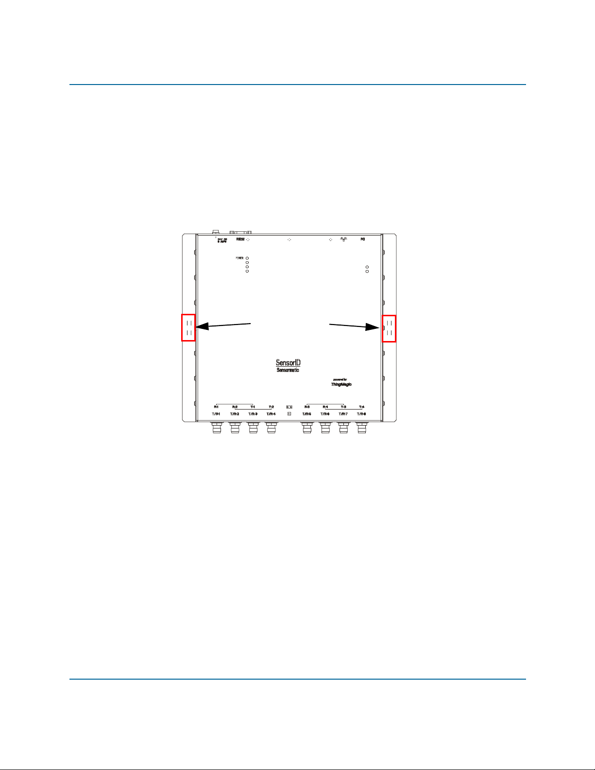
To mount the reader on a wall use the following instructions:
1. Hold the reader in its mounting location and mark the position of the two mounting
screws. The minumum screw size is #12 (M5).
MODULE A
MODULE B
FAULT / ERROR
Mounting Holes
STATUS
ACTIVITY
2. Drill holes for the screws and install wall anchors if necessary.
3. Insert the screws and tighten until almost flush with the wall.
4. Slip the reader over the screws and slide down to lock the screws in the keyhole openings.
5. Tighten the screws.
ThingMagic 7
Page 12

Mercury5 RFID Reader Installation and Service Guide Installation Requirements
Install the Antennas
The antennas can be mounted directly to a variety of surfaces. Follow the installation instructions
provided with the antennas and refer to Appendix A
for information about antennas from different
manufacturers.
One to four dual antennas can be connected to the reader, depending on the number of cards
installed. Silk-screen markings on the reader identify the cards installed.
Connect the Reader
1. Connect the required UHF antennas to the ports on the reader (see the figure Antenna
Connection Options).
Note
IMPORTANT: Connect antennas to the ports before applying power to the reader.
Any port not having an antenna connected to it will be disabled when the reader is
powered on.
Antenna Connection Options
4
3
TX
2
1
4
3
RX
2
1
2. Verify that all antennas are securely connected.
8 Installation and Service Guide
Page 13

Mercury5 RFID Reader Installation and Service Guide Installation Requirements
3. Connect the reader to the network by plugging an Ethernet cable into the Ethernet port.
or
Connect the reader to a PC (personal computer) by plugging a crossover Ethernet cable
into the Ethernet port.
[If DHCP is to be used, then the network must be connected before powering up the
reader.]
4. Plug the transformer provided with the reader into the DC power input connector. Then
connect the transformer to a power outlet.
A = RJ-45 Ethernet port C = RS-232
B = Safe Mode button D = DC power input
When the reader powers up, one green, one yellow, and one red light comes on.
After approximately 30 seconds, all lights except the green one will go out; the green light will
blink after the reader finishes its power-on self-test.
The reader is now ready for operation.
ThingMagic 9
Page 14

Mercury5 RFID Reader Installation and Service Guide Installation Requirements
Reader Configuration
In some cases, the application software may provide support for reader configuration. If so, follow
the instructions provided with the application.
The following procedure describes how to configure the reader directly from a network PC using
the browser-based interface.
The reader is shipped with the following default network configuration:
IP Address
Subnet Mask
Gateway
You must know the IP address and subnet mask settings for the network environment in which the
reader will be running.
1. Exit any reader applications that are running on the network.
10.0.0.101
255.0.0.0
10.0.0.1
Note
IMPORTANT: Running another reader application while using the browser-based
interface may cause a reader error. If this happens, reboot the reader or restart the
system using the browser-based interface.
2. Verify that the reader is operational. All LED’s should be out except for the green power
LED which should be pulsing.
3. Start a Java-enabled web browser from any network-enabled PC. This PC must be
configured with an IP address and subnet mask compatible with the reader default
settings.
For example:
IP Address
Subnet Mask
4. Browse to…
http://10.0.0.101
The Mercury5 Reader browser-based interface to the tag reader is displayed.
10 Installation and Service Guide
10.0.0.101
255.0.0.0
Page 15

Mercury5 RFID Reader Installation and Service Guide Installation Requirements
5. Click the Settings link in the navigation menu. The Modify Settings page appears.
6. These setting apply to both the LAN interface and the wireless interface. If you wish to
use DHCP select the DHCP? Yes radio button; otherwise, enter the required network
settings in the IP Address, Subnet Mask, and Gateway fields. The fields will turn red if the
gateway is not on the same subnet as the IP address. Then, click the Save Changes button.
Note
IMPORTANT: Do not disconnect power until the save process is complete.
7. Set the reader RF power to correspond to antenna and cable types. Refer to Appendix A.
8. Verify that the settings shown are correct. Then, restart the reader by disconnecting the
power cable and then reconnecting it (see Rebooting the Reader on page 24).
It may take several seconds for the reader to restart. If the IP address was changed, you
must type the new address into the browser address field to communicate with the reader.
9. Once the system restarts, click Save Changes. You are taken to the Settings Modified
page. Your changes will be saved and then applied. After the reader reconfigures its
network interfaces, it will automatically redirect you to its status page. There is no need to
restart the reader.
Note
IMPORTANT: Do not disconnect power while the reader is saving its new
configuration.
10. The reader is now ready to receive commands from the network.
11. Use the Query page of the browser-based interface to verify antenna operation.
12. Close the browser window. Start the reader application on the network.
ThingMagic 11
Page 16

Mercury5 RFID Reader Installation and Service Guide Installation Requirements
Reader Service
Using the Browser-Based Interface
The Mercury5 Reader browser-based interface communicates directly with the RFID reader. It
includes several tools that enable you to monitor reader performance, change reader settings, and
upgrade reader firmware.
A navigation menu provides access to the following pages:
Status—Displays current operational settings.
Query—Allows the user to set frequency of operation, set antennas, set RF air interface
protocols, and read tags.
Write—Allows the user to write tags; this is only applicable to tags that are writeable.
Settings—Allows the user to modify network settings.
Firmware—This page can be used to upgrade the tag reader with new firmware images
supplied by ThingMagic.
Restart—Allows the user to restart the reader.
Diagnostics—This page provides the current operating settings of the reader.
Help—This page provides information that is helpful in operating the tag reader.
The browser-based interface can be run from any PC on the network. Care must be taken to
configure the PC with an IP address and subnet mask compatible with the current operational
settings of the reader.
To start the browser-based interface:
1. Exit all reader applications on the network.
Note
IMPORTANT: Running another reader application while using the browser-based
interface may cause a reader error. If this happens, reboot the reader or restart it
using the browser-based interface.
2. Start a Java-enabled web browser from any network-enabled PC.
3. Ty pe the IP address of the reader you want to communicate with in the Address field of the
browser.
4. A navigation menu and the Current Operational Settings page appear in the browser.
12 Installation and Service Guide
Page 17

Mercury5 RFID Reader Installation and Service Guide Installation Requirements
Status Page
The Reader Status page shows the current settings of the reader.
1. Click the Status link in the navigation menu to display the Current Operational Settings
page.
2. Close the browser window if you are finished using the browser-based interface.
ThingMagic 13
Page 18

Mercury5 RFID Reader Installation and Service Guide Installation Requirements
Query Page
Use the Query page to monitor reader performance. The Query page is useful for verifying
performance when installation is complete and for troubleshooting performance issues.
The Query field includes a drop-down list (at the bottom-right of the screen) that enables you to
specify the operating mode. The operating mode specifies the tag protocols and antenna ports to be
used in conjunction with the Query page.
Note
The selected settings DO NOT affect reader performance associated with other
applications.
The following operating modes are available for use with the Query page:
Selection Description
EPC1 CC915 protocol tags using both UHF
antenna ports
CC915@UHF1 CC915 protocol tags using UHF port 1
CC915@UHF2 CC915 protocol tags using UHF port 2
ALL All protocols using all ports
14 Installation and Service Guide
Page 19

Mercury5 RFID Reader Installation and Service Guide Installation Requirements
1. Click the Query link on the navigation menu. The Query page appears.
2. Select the operating mode from the pull-down list.
3. Click the Start button to begin reading tags.Tag data is displayed. Each entry shows
sequential tag number, number of times tag was read, tag data, antenna, and pr oto col.
4. Click Stop to stop the tag search.
Note
IMPORTANT: You MUST stop the query before exiting the browser-based
interface or the reader will continue to poll antennas.
The Query page provides additional options that enable you to control the data that is gathered and
how it is displayed:
Bignum checkbox (when checked) displays the total number of unique tags read. The
total is displayed in large red numbers directly over the tags read list.
ThingMagic 15
Page 20

Mercury5 RFID Reader Installation and Service Guide Installation Requirements
Show Raw button displays raw tag data on the Query page. Each entry shows reader,
protocol, antenna, and tag data.
Hide Raw button stops the display of raw tag data.
Clear Output button clears the data displayed.
Query Once button initiates a single search cycle after clicking Start.
Writ e Page
Use the Write page to replace the EPC data that is encoded on a 915 MHz EPC Class 1 tag.
16 Installation and Service Guide
Page 21

Mercury5 RFID Reader Installation and Service Guide Installation Requirements
Consider the following guidelines when writing to tags:
Always place a tag 0.3–0.6m (1–2ft) from the antenna when writing data. The tag may
be damaged if it is too close to the antenna.
Only unlocked 915 MHz tags can be used. The write function is not supported for 13.56
MHz tag protocols.
The data to be written must be exactly 16 hexadecimal characters (numerals from 0–9
and letters from A–F).
Always place only one tag in the antenna’s field when writing. If multiple tags are
present, they will all be encoded with the same EPC data.
Use the antenna connected to UHF1.
To write data to a tag:
1. Click the Write link on the navigation menu. The Write page appears.
2. In the top pane, type or paste the 16-character hexadecimal data to be written to the tag.
3. Highlight the hexadecimal data.
4. Click the Make Update button. A query designed to write the highlighted data to the tag
appears in the center pane.
5. Place the tag 0.3–0.6m (1–2ft) from the antenna connected to UHF1.
6. Verify that no other tags are in the antenna’s field.
7. Click the Submit Query button to write the data. If the write was successful, the new tag
data appears in the bottom pane.
To read data from a tag:
1. Display the Write page (click the Write link on the navigation menu).
2. Click the Make Select button. A query designed to read data from the antenna connected
to UHF1 appears in the center pane.
3. Place the tag to be read within the detection zone of the antenna.
4. Click the Submit Query button to read tag data. Query results appear in the bottom pane.
ThingMagic 17
Page 22

Mercury5 RFID Reader Installation and Service Guide Installation Requirements
Settings Page
Use the Modify Settings page to change network settings.
1. Click the Settings link on the navigation menu. The Modify Settings page appears.
2. Enter the required settings.
3. Click the Save button to save the new settings.
Note
IMPORTANT: Do not disconnect power until the save process is complete.
The new settings DO NOT take effect until the reader is restarted by rebooting the reader (see
Rebooting the Reader
18 Installation and Service Guide
on page 24).
Page 23

Mercury5 RFID Reader Installation and Service Guide Installation Requirements
Instructions for Modifying the Settings
Changing these parameters changes the values used on startup. The set of variables that can be
changed affects both the network settings and radio settings. Even though basic validity checking
is performed, care must be taken to use correct values. Changing between static network settings
and DHCP will change what fields are valid--static network settings are ignored when in DHCP
mode, and DHCP related settings are ignored when in static IP mode.
dhcp? This radio button determines whether the tagreader uses DHCP to
obtain an IP address or static networking.The d e fau lt value is Yes.
dhcpcd_ixp1 This parameter sets the flags passed to the dhcpcd process. Typical
settings include -h hostname and -t timeout_in_secs. The default
value is -t 15 -h Mercury5.
ipaddr_ixp1 This setting specifies the IP address used when the reader uses static
addressing. It is an IP address in dotted-quad notation. The default
value is 10.0.0.101.
netmask_ ixp1 This setting specifies the netmask used when the reader uses static
broadcast_ixp1 This setting specifies the broadcast address used when the reader
gateway This setting specifies the gateway to use when the reader uses static
uhf_power_centidbm This setting specifies the UHF power output level, measured in
addressing. It is specified in dottedquad notation. The default value
is 255.255.255.0.
uses static addressing. It is specified in dotted-quad notation. The
default value is 255.255.255.0.
addressing. It is specified as device_name/gateway_ip_address. The
default value is ixp1/10.0.0.1.
centidBm. The default value is 3000 (equal to 30.00 dBm.)
ThingMagic 19
Page 24

Mercury5 RFID Reader Installation and Service Guide Installation Requirements
Firmware Upgrade Page
1. Click the Firmware link on the navigation menu. The Firmware Upgrade page appears.
2. Place the cursor in the Filename field and type the complete network pathname of the
firmware file or click the Browse button to locate the new firmware file.
3. Click the Upgrade button to download the new firmware to the reader.
4. The status frame at the bottom of the page displays the progress of the upgrade if the web
browser supports automatic page reload. Click the Refresh button to update the status bar
if the web browser does not support automatic page reload.
5. Downloaded firmware IS NOT implemented until the reader is restarted.
6. If an error occurs during the firmware upgrade, use Safe Mode to recover.
20 Installation and Service Guide
Page 25

Mercury5 RFID Reader Installation and Service Guide Installation Requirements
Restart Page
Use the Restart Page to restart the reader.
1. Click the Restart link on the navigation menu.The Restart Reader page appears.
2. To restart the reader, click the Restart System button. A dialog box appears asking if you
want to restart the reader.
3. Click OK. The following message appears and remains on the screen until the reader
restarts. Then the Status page appears.
ThingMagic 21
Page 26
Mercury5 RFID Reader Installation and Service Guide Installation Requirements
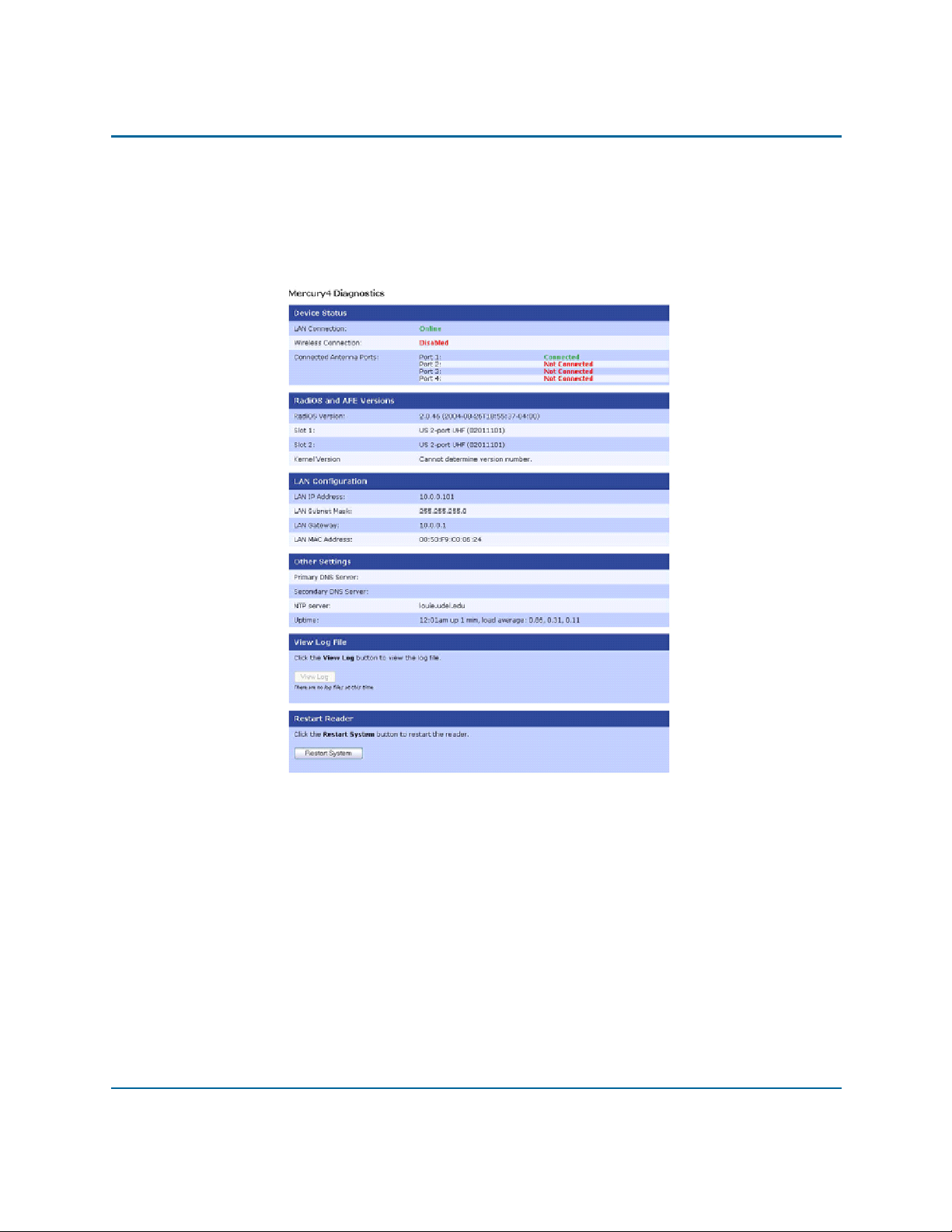
Diagnostics Page
The diagnostics page provides a wealth of information, including the current setings of the reader,
comprenhensive version information, and current status of network interfaces.
22 Installation and Service Guide
Page 27

Mercury5 RFID Reader Installation and Service Guide Installation Requirements
Help Page
Use the Help page to view descriptions of system operations.
ThingMagic 23
Page 28

Mercury5 RFID Reader Installation and Service Guide Installation Requirements
Rebooting the Reader
Use this procedure to recover from a reader error.
1. Disconnect power from the reader.
2. Re-connect reader power.
3. Wait for at least 60 seconds for the reader to boot up. The Power/Heartbeat LED remains
solid green while the reader boots.
When the LED begins blinking, the boot process is complete.
Using Safe Mode
Use the Safe Mode button on the reader connector panel to recover from errors that disable the
reader.
Safe mode operation restores factory default settings as follows:
Firmware Version: ..................factory installed version
UHF (915 MHz) RF Transmit Power:.......................30
IP Address: ...................................................10.0.0.101
Subnet Mask:..................................................255.0.0.0
Gateway:...........................................................10.0.0.1
Although the browser-based interface pages are displayed in red when operating in Safe mode, the
reader is fully functional. In most cases, the reader will need to be reconfigured for operation with
the reader application after starting in Safe mode.
1. Disconnect power from the reader.
2. Depress and hold the Safe Mode button while restoring power to the reader . Keep the Safe
Mode button depressed until the reader boots completely (the green Power/Heartbeat LED
blinks).
3. Factory-default settings are restored.
24 Installation and Service Guide
Page 29

Mercury5 RFID Reader Installation and Service Guide Installation Requirements
4. Use the browser-based interface to configure the reader for use with your system. This PC
must be configured with an IP address and subnet mask compatible with the reader default
settings. For example: IP address 10.0.0.10, net mask 255.0.0.0.
5. Click the Settings link on the navigation menu and verify the new settings.
6. Restart the reader with the new settings. Once the restart is complete, the reader is no
longer in Safe Mode.
ThingMagic 25
Page 30

Mercury5 RFID Reader Installation and Service Guide Installation Requirements
Specifications
Electrical
Reader
UHF operating frequency........................... 902–928MHz
Input voltage.................................................24Vdc, 2.0A
Separate Power Supply
Input voltage...................Nominal 100–240Vac, 50/60Hz
AC line current .............................Nominal 0.5A at 120V
Output voltage ...................... Nominal 24Vdc, 2.5A peak
Certified limited power source
Class 2
Environmental
Operating temperature:............ 0° to 40°C (32° to 104°F)
Relative humidity: ....................0 to 90% non-condensing
Mechanical
Reader
Length......................................................26.5cm (10.4in)
Width.......................................................26.6cm (10.4in)
Width (with mounting bracket) ..................30.5cm (12in)
Depth ...........................................................3.8cm (1.5in)
Weight ...........................................................1.4kg (3 lbs)
26 Installation and Service Guide
Page 31

Mercury5 RFID Reader Installation and Service Guide Installation Requirements
Supported Tag Protocols
915 MHz........................................................EPC Class 1
.......................................................................EPC Class 0
...................................................................ISO 18000-6B
..................................................................................Gen2
Declarations
Regulatory Compliance
EMC.........................................................47 CFR, Part 15
Safety................................................................UL 60950
Can/CSA C22.2 No 60950
EN 60950
FCC COMPLIANCE: This equipment complies with Part 15 of the FCC rules for intentional
radiators and Class A digital devices when installed and used in accordance with the instruction
manual. Following these rules provides reasonable protection against harmful interference from
equipment operated in a commercial area. This equipment should not be installed in a residential
area as it can radiate radio frequency energy that could interfere with radio communications, a
situation the user would have to fix at their own expense.
EQUIPMENT MODIFICATION CAUTION: Equipment changes or modifications not
expressly approved by ThingMagic LLC, the party responsible for FCC compliance, could void
the user's authority to operate the equipment and could create a hazardous condition.
IMPORTANT USER INFORMATION: In order to comply with FCC requirements for RF
exposure safety , a separation distance of at least 22 cm (8.7in) needs to be maintained between the
radiating elements of the antenna and the bodies of nearby persons.
Other Declarations
WARRANTY DISCLAIMER: ThingMagic LLC makes no representation or warranty with
respect to the contents hereof and specifically disclaims any implied warranties of merchantability
or fitness for any particular purpose. Further, ThingMagic LLC reserves the right to revise this
publication and make changes from time to time in the content hereof without obligation of
ThingMagic LLCto notify any person of such revision or changes.
ThingMagic 27
Page 32

Mercury5 RFID Reader Installation and Service Guide Installation Requirements
LIMITED RIGHTS NOTICE: For units of the Department of Defense, all documentation and
manuals were developed at private expense and no part of it wa s developed using Government
Funds. The restrictions governing the use and disclosure of technical data marked with this legend
are set forth in the definition of “limited rights” in paragraph (a) (15) of the clause of DFARS
252.227.7013. Unpublished - rights reserved under the Co pyright Laws of the United States.
TRADEMARK NOTICE: ThingMagic and the ThingMagic logo are trademarks or registered
trademarks of ThingMagic LLC. Other product names mentioned herein may be trademarks or
registered trademarks of ThingMagic LLCor other companies.
No part of this guide may be reproduced in any form without written permission from ThingMagic
LLC.
28 Installation and Service Guide
Page 33

Appendix A
Authorized Antennas
The only antennas authorized by the FCC for use with the Mercury5 Reader are in the tables
below. Detailed information on each antenna is available from their respective manufacturers.
Note
IMPORTANT: No other antennas may be used with the Mercury5 Reader without
violating FCC regulations. It is the responsibility of the user to comply with this
requirement.
ThingMagic Dual Antenna Sensormatic OMNIPOINT Antenna
Model TM-ANT-2 IDANT10LNA25
Gain 6 dBi max 5.75 dBi max
Connector Reverse TNC Reverse TNC
M/A-COM Dual Antenna Matrics General Purpose Antenna
Model MAANAT0141 ANT-GPHP
Part No. 250012-001
Gain 5.9 dBi max. 5.75 dBi max.
Connector Reverse TNC Type N
Alien Dual Antenna
(Circular/Linear)
Model ALR9611-C+L ALR9611-CR+CL
Gain 6 dBi max. 6 dBi max.
Connectors integral 20' cable with reverse TNC integral 20' cable with reverse TNC
ThingMagic 1
Alien Dual Antenna (RH/LH Circular)
Page 34

Appendix A Authorized Antennas
Model
Gain
Connectors
Cables
Note
The two Accusort antennas are used with a special set of cables and circulator, as
noted above. Do not use these antennas with other cables.
Accusort Ramp Bottom
Antenna
Accusort Shelf Antenna
0107161001 0107164001
10 dBi max. 10 dBi max.
Mini UHF Type N
2' LMR-195 + circulator + 10'
LMR-240 (total loss = 1.45 dB)
or
2' LMR-195 + circulator + 20'
LMR 240 (total loss 2.25 dB)
2' LMR-195 + circulator + 10' LMR-240
(total loss = 1.55 dB)
or
2' LMR-195 + circulator + 20' LMR 240
(total loss 2.35 dB)
2 API Reference Guide
Page 35

Appendix A Antenna Cables
Antenna Cables
The only cables authorized by the FCC for use with the Mercury5 are in the table below:
Long TNC/TNC Long TNC/N
ThingMagic P/N TM-M5CAB-TT-P25 TM-M5CAB-TN-P25
Length 25’ 25’
Insertion Loss 2.5 dB min. 2.5 dB min.
Cable Type Cable Type: LMR-195 Cable Type: LMR-195
Connectors Reverse TNC to Reverse TNC Reverse TNC to Type N
Short TNC/TNC Short TNC/N
ThingMagic P/N
Length 6’ 6’
Insertion Loss
Cable Type
Connectors
TM-M5CAB-TT-P6 TM-M5CAB-TN-P6
0.6 dB min. 0.6 dB min.
LMR-195 LMR-195
Reverse TNC to Reverse TNC Reverse TNC to Type N
ThingMagic 3
Page 36

Appendix A Antenna Cables
4 API Reference Guide
 Loading...