

Page 1

MPRX-FH Reader
User Guide
16-0142-001 Rev A 1/2020
TransCore’s Multiprotocol Reader Extreme Frequency Hopper (MPRX-FH) is a radio
frequency identification (RFID) reader designed for harsh environment applications.
This guide provides site planning, testing, and operating instructions for this system.
This guide is intended for use by authorized TransCore dealers, professional
installers, and service personnel. The MPRX-FH must be installed by a professional
installer. Once installed, configured, and verified by testing, the end user cannot
change the configuration (transmit power, etc) of the MPRX-FH. If changes are
required, the end user must contact their authorized TransCore dealer, professional
installer, and/or service personnel for additional service.
Trusted Transportation Solutions
Page 2

MPRX-FH User Guide
Information in this document is subject to change and does not represent a commitment on the part of
TransCore, LP.
© 2020 TransCore, LP. All rights reserved. TRANSCORE, AMTECH, EGO, and ENCOMPASS are registered
trademarks and are used under license. All other trademarks are the property of their respective owners.
Contents are subject to change. Printed in the U.S.A.
For further information, contact:
TransCore
8600 Jeerson Street NE
Albuquerque, New Mexico 87113 USA
TransCore Technical Support
Phone: (505) 856-8007
Web: www.transcore.com
TransCore Sales Support
Phone: (800) 923-4824
Lantronix ® Technical Support (Ethernet Support)
Phone: (949) 453-7198
Web: www.lantronix.com/support/
ii
Page 3

Approved Antenna List
TRANSMITTERS FOR DETACHABLE ANTENNAS
This radio transmitter, ISED ID: 1584A-MPRXV1, has been approved by Innovation, Science, and Economic
Development Canada to operate with the antenna types listed below, with the maximum permissible gain
indicated. Antenna types not included in this list that have a gain greater than the maximum gain indicated
for any type listed are strictly prohibited for use with this device.
The MPRX-FH complies with FCC Part 15.247 and IC RSS-247 rules and has been designed to operate with
the listed antennas presented in Table 1. The eective maximum gain of each antenna is listed as well as
the required attenuation to ensure that eective gain of greater than the allowed 6dB cannot occur. The
required attenuation presented in Table 1 also includes any cable loss that is included with the system.
To reduce potential interference to other systems, antenna gain and type should be selected in a way that
the EIRP (equivalent isotropically radiated power) is no more than the allowed 36dBm, preferably as low as
possible that is needed for proper operation of the system.
Table 1 Approved Antenna List
FCC COMPLIANCE NOTICE
Manufacture Part Number Polarization
Huber Suhner 1309.17.0111/85018546 Circular 5.50 0.00
Kathrein 52010087 Circular 11.00 5.00
Kathrein 52010249 Linear 11.00 5.00
Kathrein 52010092 Circular -30.00 0.00
Laird S9028P Linear 8.00 2.00
Laird S9025PR Circular 5.50 0.00
MARS Antennas & RF
Systems LTD.
Mobile Mark PN6-915RCP-1C-WHT-6 RH Circular 6.00 0.00
Mobile Mark PN6-915LCP-1C-WHT-6 LH Circular 6.00 0.00
Mobile Mark PL8-915RCP-1Y-WHT-12 RH Circular 8.00 2.00
Mobile Mark HD7-915RCP-BLK RH Circular 7.00 1.00
MTI Wireless Edge LTD. MT-263007/TRH/A/K Circular 11.50 5.50
TransCore AA3152 UTA Linear 14.00 8.00
TransCore AA3237 Linear 6.00 0.00
TransCore AA3110 Linear 12.50 6.50
TransCore AA3153 Linear 10.50 4.50
MA-IS91-T2 Linear 10.50 4.50
Gain
(dBi)
Min lnline Loss
Required (dB)
Table 1 has the antenna polarization, peak linear dBi (decibels over isotropic) gain figures, and the
required loss required between the MPRX-FH and the antenna. This loss can include the cable loss for the
length of the cable required to set up system.
Example:
To set up an MPRX-FH reader for use with the AA3152 antenna using a cable length of LMR-400 with an
average attenuation of 3.94dBi and a length of 115ft, the cable loss would be 4.53dBi. With a gain of 14dBi
iii
Page 4

MPRX-FH User Guide
from the AA3152, and another external attenuator with a value of at least 3.47dBi or greater, this setup
would meet the FCC rule of the maximum EIRP of 36dBm.
Liste des antennes approuvées
ÉMETTEURS RADIO POUR ANTENNES DÉMONTABLES
o
Cet émetteur radio, n
Développement économique Canada pour fonctionner avec les types d’antennes qui figurent dans la liste
ci-dessous, sous réserve du gain maximal admissible indiqué. Il est strictement interdit d’utiliser tout type
d’antenne qui ne figure pas sur cette liste et dont le gain est supérieur au gain maximal indiqué sur la liste,
tous types confondus, avec cet appareil.
Le MPRX-FH est conforme à la section15.247 des règles de la FCC et aux règles du CNR-247, et est
conçu pour fonctionner avec les antennes énumérées dans la liste du tableau1. La liste prescrit le gain
maximal apparent de chaque antenne, ainsi que l’atténuation requise pour faire en sorte qu’un gain
apparent supérieur aux 6dB admis ne peut se produire. L’atténuation requise indiquée au Tableau 1
comprend en outre toute atténuation de câble qui est comprise dans le système.
ISDE 1584A-MPRXV1, a obtenu l’homologation d’Innovation, Sciences et
AVIS DE CONFORMITÉ À LA FCC
Pour limiter les interférences potentielles sur d’autres systèmes, le gain et le type d’antenne doivent être
choisis de sorte que la puissance isotrope rayonnée équivalente (p.i.r.e.) ne dépasse pas les 36dBm
admissibles et, de préférence, soit la plus faible possible compte tenu des exigences de fonctionnement
du système.
Tableau1 – Liste des antennes approuvées
Fabricant Numéro de pièce Polarisation
Huber Suhner 1309.17.0111/85018546 Circulaire 5,50 0,00
Kathrein 52010087 Circulaire 11,00 5,00
Kathrein 52010249 Linéaire 11,00 5,00
Kathrein 52010092 Circulaire -30,00 0,00
Laird S9028P Linéaire 8,00 2,00
Laird S9025PR Circulaire 5,50 0,00
MARS Antennas & RF
Systems LTD
Mobile Mark PN6-915RCP-1C-WHT-6
Mobile Mark PN6-915LCP-1C-WHT-6
Mobile Mark PL8-915RCP-1Y-WHT-12
Mobile Mark HD7-915RCP-BLK
MTI Wireless Edge LTD MT-263007/TRH/A/K Circulaire 11,50 5,50
MA-IS91-T2 Linéaire 10,50 4,50
Circulaire sens
horaire
Circulaire sens
antihoraire
Circulaire sens
horaire
Circulaire sens
horaire
Gain
(dBi)
6,00 0,00
6,00 0,00
8,00 2,00
7,00 1,00
Atténuation de
câble minimale
requise (dB
)
iv
Page 5

TransCore AA3152 UTA Linéaire 14,00 8,00
TransCore AA3237 Linéaire 6,00 0,00
TransCore AA3110 Linéaire 12,50 6,50
TransCore AA3153 Linéaire 10,50 4,50
Le tableau1 indique la polarisation de chaque antenne, le gain linéaire maximal en dBi (décibels par rapport à
l’antenne isotrope) et l’atténuation requise entre le MPRX-FH et l’antenne. Cette atténuation peut comprendre
l’atténuation de câble sur toute la longueur de câble requise pour installer le système.
Par exemple:
Pour installer un lecteurMPRX-FH à utiliser avec l’antenneAA3152 au moyen d’un câbleLMR-400 à
atténuation moyenne de 3,94dBi, d’une longueur de 115pi, l’atténuation de câble serait de 4,53dBi. Le
gain de l’antenneAA3152 étant 14dBi, en utilisant un autre atténuateur externe d’une valeur de 3,47dBi
ou plus, cette installation respecte la p.i.r.e maximale de 36dBm imposée par la FCC.
v
Page 6

MPRX-FH User Guide
NOTE: This equipment has been tested and found to comply with the limits for a Class A
digital device pursuant to Part 15 of the FCC rules. These limits are designed to provide
reasonable protection against harmful interference when the equipment is operated in
a commercial environment. This equipment generates, uses, and can radiate RF energy
and may cause harmful interference to radio communications if not installed and used in
accordance with the instruction manual. Operating this equipment in a residential area is likely
to cause harmful interference, in which case, depending on the laws in eect, the user may be
required to correct the interference at their own expense.
CAUTION:
This equipment may not be modified, altered, or changed in any way without permission.
Unauthorized modification may void the equipment authorization from the FCC and will void
the warranty.
TO USERS IN THE UNITED STATES
FEDERAL COMMUNICATIONS COMISSION FCC
RADIO FREQUENCY INTERFERENCE STATEMENT
47 CFR §15.105A
NO UNAUTHORIZED MODIFICATIONS
47 CFR §15.21
USE OF SHIELDED CABLES AND GROUNDING
47 CFR §15.27A
NOTE: Shielded cables and earth grounding the unit is recommended for this equipment to
comply with FCC regulations.
TRANSCORE, LP
USA
vi
Page 7

AVERTISSEMENT À L’ATTENTION DES
UTILISATEURS AUX ÉTATSUNIS
DÉCLARATION 47 CFR §15.105A DE LA FCC SUR
LES INTERFÉRENCES DES FRÉQUENCES RADIO
REMARQUE : Cet appareil a été testé et déclaré conforme à la catégorie d’un appareil
numérique de classe A en accord avec la partie 15 des directives de la FCC. Ces normes visent
à assurer une protection raisonnable contre les interférences nuisibles lorsque l’appareil est
utilisé dans un environnement commercial. Cet appareil génère, utilise et peut émettre de
l’énergie RF et peut être à l’origine d’interférences nuisibles aux communications radio s’il n’est
pas installé et utilisé en suivant les directives du manuel d’instructions. Si cet appareil est utilisé
dans une zone résidentielle, il est probable qu’il cause des interférences nuisibles. Dans ce cas,
l’utilisateur pourrait être amené à remédier aux interférences à ses propres frais, selon les lois
du pays en vigueur.
AUCUNE MODIFICATION NON AUTORISÉE
47 CFR §15.21
MISE EN GARDE : IL EST INTERDIT DE MODIFIER, D’ALTÉRER OU D’APPORTER DES CHANGEMENTS
À CET APPAREIL DE QUELQUE MANIÈRE QUE CE SOIT SANS AUTORISATION. TOUTE MODIFICATION
NON AUTORISÉE PEUT ANNULER L’AUTORISATION D’UTILISATION ACCORDÉE PAR LA FCC ET
ANNULERA LA GARANTIE.
UTILISATION DE CÂBLES BLINDÉS ET MISE À LA TERRE
47 CFR §15.27A
REMARQUE : Il est recommandé d’utiliser des câbles blindés et une mise à la terre avec cet
appareil afin de répondre aux réglementations de la FCC
TRANSCORE, LP
ÉTATSUNIS
vii
Page 8

MPRX-FH User Guide
This device contains licence-exempt transmitter(s)/receiver(s) that comply with Inovation,
Science and Economic Development Canada’s licence-exempt RSS(s). Operation is subject to
the following two conditions:
1. This device may not cause interference.
2. This device must accept any interference, including interference that may cause undesired
operation of the device.
Cet appareil contient des émetteurs(s)/récepteurs exemptés de licence qui sont conformes
à l’EXEMPTION de RSS(s) d’Innovation, Science et Developpement économique Canada). L’
opération est soumise aux deux conditions suivantes:
1 ) l'appareil ne doit pas produire de brouillage.
2 ) l'utilisateur de l'appareil doit accepter tout brouillage radioélectrique subi, même si le brouillage
est susceptible d'en compromettre le fonctionnement.
WARNING TO USERS IN CANADA
AVERTISSEMENT AUX UTILISATEURS AU CANADA
viii
Page 9

RADIO FREQUENCY HEALTH LIMITS FOR MPRXFH READER
USING AN EXTERNAL ANTENNA IN
FREQUENCY BAND OF 902 TO 928 MHZ
Several agencies (OSHA, FCC, IC) have environmental guidelines regulating maximum
permissible exposure (MPE) or “safe” exposure levels that this product falls under. To ensure
that proper safety guideline for the end users of this product, i.e. Occupational (Controlled) and
General Population/Public (Uncontrolled), the recommended levels for each of the agencies are
presented in the next sections with TransCore’s recommendations for safety in the last section.
OSHA (Occupational Safety and Health Administration)
OSHA (an agency of The United States of America) legislates in the Code of Federal
Regulations (CFR) Title 29 Part 1910 Subpart G 1910.97 titled “Nonionizing radiation”, a maximum
2
safe exposure limit of 10 milliwatts per square centimeter (mW/cm
) during any 0.1-hour period
(i.e. 6 minutes). Using the frequency (in the middle of the band of operation of this equipment)
of 915 MHz and the highest antenna gain that this equipment is certified for use in a final
installation, the minimum safe distance was calculated to be 8in (20cm).
FCC (Federal Communication Commission)
FCC (an agency of The United States of America) legislates in the Code of Federal Regulations
(CFR) Title 47 Chapter I Subchapter A Part 1 Subpart I Section 1.1310 titled “Radiofrequency
radiation exposure limits” that the maximum permissible exposure (MPE) is the following:
Occupational/Controlled Exposure
2
Power density = frequency(in MHz)/300 mW/cm
with an Averaging time of 6 Min
General Population/Uncontrolled Exposure
2
Power density = frequency(in MHz)/1500 mW/cm
with an Averaging time of 30 Min
Using the frequency (in the middle of the band of operation of this equipment) of 915MHz
and the highest antenna gain that this equipment is certified for use in a final installation,
the minimum safe distance was calculated. The MPE minimum distances are 14in (36cm) for
the Occupational/Controlled environment, and 31.5in (80.5cm) for the General Population/
Uncontrolled environment.
Industry Canada (Innovation, Science and Economic Development Canada)
Industry Canada (a Department of the Government of Canada) sets out the requirements in
Radio Standards Specification RSS-102, Issue 5 guidelines, recommending a maximum safe
2
power density in W/m
uncontrolled exposure at 915MHz is 2.77 W/m
. Thus, the maximum permissible exposure for general population/
2
. The average time is 6 minutes. The maximum
permissible exposure (MPE) is the following:
Controlled Environment
0.5
Power density = 0.6455*frequency(in MHz)
W/m2 with a Reference Period time of 6 Min
ix
Page 10

MPRX-FH User Guide
Power density = 0.02619*frequency(in MHz)
Using the frequency (in the middle of the band of operation of this equipment) of 915MHz
and the highest antenna gain that this equipment is certified for use in a final installation, the
minimum safe distance was calculated. The MPE minimum distances are 13in (32cm) for the
Controlled environment and 33in (84cm) for the General Public/Uncontrolled environment.
TransCore Recommendation on MPE (Maximum Permissible Exposure)
The calculated power densities and MPE distance for each of the agencies respective to the
environment is shown below.
General Public/Uncontrolled Environment
0.6834
W/m2 with a Reference Period time of 6 Min
Occupational/Controlled Environment
Agency Power Density
MPE minimum distance Time (min)
(mW/cm2)
in cm
OSHA 10 5.5 14 6
FCC 3.05 10.2 26 6
IC 1.95 12.6 32 6
General Population/Public/Uncontrolled Environment
Agency Power Density
MPE minimum distance Time (min)
(mW/cm2)
In cm
OSHA 10 5.5 14 6
FCC 0.61 22.0 56 30
IC 0.28 33.0 84 6
With the equipment installed and running at the maximum transmit power of 1.0W (30dBm),
0 dB transmit attenuation, using a 6dBi gain antenna that the equipment is certified for, the
recommendation for each of the operation environments is as follows:
1 ) The antenna should be installed at least 33in (84cm) from the General Population/Public i.e.
Uncontrolled Environment.
2 ) Maintenance personnel (i.e. Occupational/Controlled Environment) must remain at least 13in
(32cm) from the antenna and limit their time in the environment to 6 minutes when the system
is operating.
x
Page 11

LIMITES D’EXPOSITION AUX RADIOFRÉQUENCES POUR LE LECTEUR MPRXFH
UTILISANT UNE ANTENNE EXTERNE SUR LA BANDE
DE FRÉQUENCES DE 902.25 À 903.75 ET DE 910.00 À 921.50 MHZ
Plusieurs organismes (OSHA, FCC, IC) publient des directives environnementales qui
recommandent des limites d’exposition maximale autorisée (normes MPE) ou des niveaux
d’exposition «sûrs» auxquels cet appareil se conforme. Pour faire en sorte que chaque
utilisateur final ait connaissance des directives de sécurité qui le concerne, que ce soit
dans son travail (accès contrôlé) ou pour la population générale/le grand public (accès non
contrôlé), TransCore présente les niveaux recommandés par chaque organisme dans ses
recommandations sécuritaires détaillées dans la dernière section.
OSHA (Occupational Safety and Health Administration)
Dans le Code des réglementations fédérales (CFR), Titre 29, Partie 1910, Sous-partie G 1910.97,
intitulée «Nonionizing radiation» (Rayonnements non ionisants), l’OSHA (organisme américain)
recommande un plafond d’exposition maximale de 10 milliwatts par centimètre carré (mW/
2
) pendant une période de 0,1 heure (soit 6 minutes). En utilisant la fréquence de 915 MHz
cm
(milieu de la bande de fréquences de cet appareil) et le gain d’antenne maximal pour lequel cet
appareil a reçu une certification d’utilisation dans une installation finale, la distance minimale
sécuritaire est de 20 cm (8 po).
FCC (Federal Communication Commission)
Dans le Code des réglementations fédérales (CFR), Titre 47, Chapitre I, Sous-chapitre A, Partie
1, Sous-partie I, Section 1.1310 intitulée «Radiofrequency radiation exposure limits» (Limites
d’exposition aux rayonnements de radiofréquence), la FCC (organisme américain) établit les
limites d’exposition maximale autorisée (normes MPE) comme suit :
Exposition professionnelle/contrôlée
2
Densité de puissance = fréquence (en MHz)/300 mW/cm
avec une durée moyenne de 6 min.
Exposition de la population générale/non contrôlée
2
Densité de puissance = fréquence (en MHz)/1500 mW/cm
avec une durée moyenne de 30 min.
En utilisant la fréquence de 915 MHz (milieu de la bande de fréquences de cet appareil) et le
gain d’antenne maximal pour lequel cet appareil a reçu une certification d’utilisation dans une
installation finale, la distance minimale sécuritaire est la suivante : les distances MPE minimales
sont de 36 cm (14 po) pour l’environnement professionnel/contrôlé et de 80,5 cm (31,5 po) pour
la population générale/environnement non contrôlé.
xi
Page 12

MPRX-FH User Guide
Industrie Canada (Innovation, Sciences et Développement économique Canada)
Le Cahier des charges sur les normes radioélectriques 102, 5
(un ministère du Gouvernement du Canada) établit des recommandations pour une densité
de puissance maximale sécuritaire en W/m
population générale/non contrôlée à 915 MHz est calculée à 2,77 W/m
de 6 minutes. Les limites d’exposition maximale autorisée (normes MPE) sont les suivantes :
Environnement contrôlé
Densité de puissance = 0,6455*fréquence (en MHz)
Grand public/environnement non contrôlé
Densité de puissance = 0,02619*fréquence (en MHz)
En utilisant la fréquence de 915 MHz (milieu de la bande de fréquences de cet appareil) et le
gain d’antenne maximal pour lequel cet appareil a reçu une certification d’utilisation dans une
installation finale, la distance minimale sécuritaire est la suivante : les distances MPE minimales
sont de 32 cm (13 po) pour l’environnement professionnel/contrôlé et de 84 cm (33 po) pour le
grand public/environnement non contrôlé.
e
édition, d’Industrie Canada
2
. Ainsi, l’exposition maximale admissible pour la
2
. La durée moyenne est
0,5
W/m2 avec une durée de référence de 6
min.
0,6834
W/m2 avec une durée de référence de 6 min.
Recommandations de TransCore sur les limites d’exposition maximale autorisée (normes
MPE)
Les densités de puissance et la distance MPE calculées par chaque organisme pour un
environnement donné sont présentées ci dessous.
Exposition professionnelle/environnement contrôlé
Organisme
Densité de puissance
2
(mW/cm
)
Distance MPE minimale
Durée (en min.)
po cm
OSHA 10 5,5 14 6
FCC 3,05 10,2 26 6
IC 1,95 12,6 32 6
Population générale/environnement non contrôlé
Organisme
Densité de puissance
2
(mW/cm
)
Distance MPE minimale
Durée (en min.)
po cm
OSHA 10 5,5 14 6
xii
FCC 0,61 22,0 56 30
IC 0,28 33,0 84 6
Avec l’équipement installé et fonctionnant à la puissance de transmission maximale de
1,0 W (30dBm), 0 dB transmettent l’atténuation, à l’aide d’une antenne à gain 6dBi pour
Page 13

laquelle l’équipement est certifié, la recommandation pour chacun des environnements de
fonctionnement est la suivante:
1 ) L’antenne devrait être installée à au moins 84 cm (33 po) de la population générale/du grand
public, c’est-à-dire d’un environnement non contrôlé.
2 ) Le personnel d’entretien (c’est-à-dire dans un environnement professionnel/contrôlé) doit rester
à au moins 32 cm (13 po) de l’antenne et limiter son temps d’exposition à 6 minutes lorsque
l’appareil est en fonctionnement.
Licensing Requirements
The MPRX-FH is an end-user license exempt device certified under FCC Part 15.247 and IC RS-247. As
such, the end-user of this product is not required to file for a site license from the FCC (US) or IC (Canada).
For other countries, refer to the local laws and frequency control agencies.
Once installed by a professional installer, the end user cannot make changes to the configuration (transmit
power, etc.) of the unit.
xiii
Page 14

MPRX-FH User Guide
Table of Contents
Approved Antenna List....................................................iii
Licensing Requirements ...................................................xi
Chapter1 System Overview ............................1–17
System Description .....................................................1–17
Reader................................................................1–17
Compatible Tag Types ................................................. 1–22
Chapter2 Test Procedures ............................2–23
Required Tools and Equipment ..........................................2–23
Pre-installation Testing of the MPRX-FH ..................................2–25
Testing the MPRX-FH Circuit ............................................2–25
Connecting the Antenna(s) .............................................2–26
Connecting the Power Supply...........................................2–29
Connecting Communications ...........................................2–32
Connecting Sense Input and Sense Output Circuits ........................2–32
Chapter3 General Software Information ................3–37
Command Entry Conventions .............................................3–37
Command Response Conventions .........................................3–37
Operating Parameters .................................................3–38
Power Fail............................................................3–38
Program Download ....................................................3–38
Startup...............................................................3–39
Tag/Message Buer....................................................3–40
Chapter4Communications Protocols ................... 4–41
Introduction .......................................................... 4–41
Basic Protocol ........................................................4–42
Error Correcting Protocol ...............................................4–42
xiv
Data Inquiry Protocol ..................................................4–43
Basic Protocol and ECP Format..........................................4–43
ECP Reliability ........................................................4–50
Manually Disabling ECP for Maintenance .................................4–53
Page 15

Chapter5 Commands ................................5–55
Default Settings .......................................................5–55
Operating Modes......................................................5–55
Command List ........................................................5–56
Chapter6 Configuration . . . . . . . . . . . . . . . . . . . . . . . . . . . . . . 6–82
Configuring the Reader ................................................6–82
Terminal Emulation Software ............................................6–83
Configuring MPRX-FH Parameters ........................................ 6–86
Chapter7 Troubleshooting and Maintenance ............7–94
Error Messages .......................................................7–94
MPRX-FH Repair ......................................................7–97
Technical Support .....................................................7–97
Chapter8 AT5720 Check Tag-to-MPRX-FH ..............8–98
Required Supplies .....................................................8–98
To assemble the kit for two check tags....................................8–98
AppendixAGlossary.................................A–100
AppendixBTechnical Specifications ...................B–105
Reader Specifications .................................................B–105
AppendixC Wiring Information .......................C–108
Communications Interfaces ............................................C–108
AppendixDCommand Quick Reference ................ D–110
Command Syntax .................................................... D–110
Factory Default Settings ............................................... D–110
Numerical Command List ...............................................D–111
Alphabetical Command List............................................ D–116
AppendixE Compatible Tag Information ...............E–122
Tag Configurations ...................................................E–122
Tag Data Formats..................................................... E–123
xv
Page 16

MPRX-FH User Guide
List of Figures
Figure 1 MPRX End Views . . . . . . . . . . . . . . . . . . . . . . . . . . . . . . . . . . . . . . 1–17
Figure 2 Location of Host Port on MPRX . . . . . . . . . . . . . . . . . . . . . . . . . . . . . . 1–19
Figure 3 Pin Assignments for Host Connector . . . . . . . . . . . . . . . . . . . . . . . . . . 1–19
Figure 4 Location of Sense Port on MPRX . . . . . . . . . . . . . . . . . . . . . . . . . . . . .1–20
Figure 5 Socket Assignments for Sense Connector . . . . . . . . . . . . . . . . . . . . . . . 1–20
Figure 6 Socket Assignments for Ethernet Connector . . . . . . . . . . . . . . . . . . . . . . 1–21
Figure 7 Wiring for Audible Circuit Tester for MPRX-FH. . . . . . . . . . . . . . . . . . . . . . 2–25
Figure 8 Connect RF N-type Load or Attenuator to Reader Cable End . . . . . . . . . . . . .2–26
Figure 9 Short Load to Earth Ground . . . . . . . . . . . . . . . . . . . . . . . . . . . . . . . . 2–27
Figure 10 MPRX-FH Showing Antenna Ports . . . . . . . . . . . . . . . . . . . . . . . . . . . . 2–28
Figure 11 Location of MPRX-FH Ground Stud. . . . . . . . . . . . . . . . . . . . . . . . . . . . 2–29
Figure 12 Location of Host/Sense Ports on MPRX-FH. . . . . . . . . . . . . . . . . . . . . . . 2–30
Figure 13 Stand-alone DeviceInstaller Link. . . . . . . . . . . . . . . . . . . . . . . . . . . . . 2–33
Figure 14 DeviceInstaller Start Menu . . . . . . . . . . . . . . . . . . . . . . . . . . . . . . . .2–33
Figure 15 Connecting Directly to Computer Ethernet Port . . . . . . . . . . . . . . . . . . . .2–34
Figure 16 Multiple NIC Cards . . . . . . . . . . . . . . . . . . . . . . . . . . . . . . . . . . . . 2–34
Figure 17 Adapter Options . . . . . . . . . . . . . . . . . . . . . . . . . . . . . . . . . . . . . . 2–34
Figure 18 Check for Updates Screen . . . . . . . . . . . . . . . . . . . . . . . . . . . . . . . .2–35
Figure 19 Disable Firewall . . . . . . . . . . . . . . . . . . . . . . . . . . . . . . . . . . . . . .2–35
Figure 20 LanTronix DeviceInstaller Screen . . . . . . . . . . . . . . . . . . . . . . . . . . . .2–36
Figure 21 Xport Direct+ Device Screen . . . . . . . . . . . . . . . . . . . . . . . . . . . . . . . 2–36
Figure 22 Tag and Antenna Orientation (horizontal polarization) . . . . . . . . . . . . . . . .6–85
Figure 23 MPRX-FH RF Control Options . . . . . . . . . . . . . . . . . . . . . . . . . . . . . .6–89
Figure 24 Sense CTAG Pinouts . . . . . . . . . . . . . . . . . . . . . . . . . . . . . . . . . . .8–98
Figure 25 MPRX Exterior Case Dimensions . . . . . . . . . . . . . . . . . . . . . . . . . . . .B–106
Figure 26 MPRX End Panel Dimensions with Antenna Ports. . . . . . . . . . . . . . . . . . . B–107
Figure 27 MPRX End Panel Dimensions with Communication Connectors . . . . . . . . . .B–107
xvi
Page 17

List of Tables
Table 1 Approved Antenna List . . . . . . . . . . . . . . . . . . . . . . . . . . . . . . . . . . . . iii
Table 2 Connector Cabling Accessory Kits . . . . . . . . . . . . . . . . . . . . . . . . . . . . 1–18
Table 3 Power Supply Current Requirements . . . . . . . . . . . . . . . . . . . . . . . . . . . 1–18
Table 4 Recommended Cables . . . . . . . . . . . . . . . . . . . . . . . . . . . . . . . . . . . 1–22
Table 5 Pretest Accessory Options . . . . . . . . . . . . . . . . . . . . . . . . . . . . . . . . .2–24
Table 6 Pretest Accessory Options Available From Third Party . . . . . . . . . . . . . . . . .2–24
Table 7 Pin Assignments for Host Connector . . . . . . . . . . . . . . . . . . . . . . . . . . . 2–30
Table 8 Socket Assignments for Sense Connector . . . . . . . . . . . . . . . . . . . . . . . .2–31
Table 9 Inrush and Steady State Currents for MPRX-FH . . . . . . . . . . . . . . . . . . . . . 2–31
Table 10 Four-Character Command Structure . . . . . . . . . . . . . . . . . . . . . . . . . . .3–37
Table 11 Sample Command Sequence . . . . . . . . . . . . . . . . . . . . . . . . . . . . . . . 3–38
Table 12 Select Baud Rate Commands . . . . . . . . . . . . . . . . . . . . . . . . . . . . . . .5–57
Table 13 Select Stop Bits Commands . . . . . . . . . . . . . . . . . . . . . . . . . . . . . . . . 5–58
Table 14 Select Parity Commands . . . . . . . . . . . . . . . . . . . . . . . . . . . . . . . . . . 5–58
Table 15 Append Time and Date Commands . . . . . . . . . . . . . . . . . . . . . . . . . . .5–60
Table 16 Append Auxiliary Information Commands . . . . . . . . . . . . . . . . . . . . . . . .5–60
Table 17 Unique ID Code Criteria . . . . . . . . . . . . . . . . . . . . . . . . . . . . . . . . . .5–62
Table 18 Select Valid Code Commands and Frames . . . . . . . . . . . . . . . . . . . . . . . 5–62
Table 19 Software Flow Control Commands . . . . . . . . . . . . . . . . . . . . . . . . . . . .5–73
Table 20 RF Control Commands . . . . . . . . . . . . . . . . . . . . . . . . . . . . . . . . . . 5–74
Table 21 RF Attenuation Command Variables . . . . . . . . . . . . . . . . . . . . . . . . . . . 5–74
Table 22 Presence Without Tag Report Commands . . . . . . . . . . . . . . . . . . . . . . . 5–75
Table 23 RF Control Algorithm Commands . . . . . . . . . . . . . . . . . . . . . . . . . . . . 5–76
Table 24 Timeout Period Values . . . . . . . . . . . . . . . . . . . . . . . . . . . . . . . . . . . . 5–76
xvii
Page 18

MPRX-FH User Guide
Table 25 Input Inversion Options . . . . . . . . . . . . . . . . . . . . . . . . . . . . . . . . . .5–77
Table 26 MPRX-FH Default Configuration Settings . . . . . . . . . . . . . . . . . . . . . . . . 6–82
Table 27 Command Sequence to Verify Communications . . . . . . . . . . . . . . . . . . . .6–84
Table 28 Error Messages . . . . . . . . . . . . . . . . . . . . . . . . . . . . . . . . . . . . . .7–94
Table 29 Symptoms and Remedies . . . . . . . . . . . . . . . . . . . . . . . . . . . . . . . . . 7–95
Table 30 Check Tag 0 Wire Assignments . . . . . . . . . . . . . . . . . . . . . . . . . . . . . 8–98
Table 31 Check Tag 1 Wire Assignments . . . . . . . . . . . . . . . . . . . . . . . . . . . . . . 8–99
Table 32 MPRX Host Communications Cable Pin Designations . . . . . . . . . . . . . . . . .C–108
Table 33 Communications Interfaces and Conductor Requirements . . . . . . . . . . . . . .C–108
Table 34 MPRX SENSE Communications Cable Pin Designations. . . . . . . . . . . . . . . .C–109
Table 35 Ethernet Pin Designations . . . . . . . . . . . . . . . . . . . . . . . . . . . . . . . .C–109
Table 36 MPRX-FH Default Configuration Settings . . . . . . . . . . . . . . . . . . . . . . . .D–110
Table 37 MPRX-FH Commands Listed Numerically . . . . . . . . . . . . . . . . . . . . . . . .D–111
Table 38 MPRX-FH Commands Listed Alphabetically. . . . . . . . . . . . . . . . . . . . . . . D–116
Table 39 SeGo Protocol Tags . . . . . . . . . . . . . . . . . . . . . . . . . . . . . . . . . . . .E–122
xviii
Page 19
Chapter1 System Overview
System Description
The MPRX-FH is a reader that supports transponders formatted for ISO/IEC 18000-63 (Tag Data Standard
Protocol) and TransCore’s Super eGo® (SeGo) radio frequency identification (RFID) technology.
Operational Modes
The MPRX-FH reader can operate in several modes, depending on the application. All modes are readonly.
ISO/IEC 18000-63: This mode has applications mainly in the toll and access control environment.
SeGo: This mode has applications mainly in the toll and access control environment.
The operational mode of the reader is limited by the firmware load, and also by enabling or disabling the
modes using the appropriate #4NN commands, as defined in “Chapter 5 Commands” on page 5–57.
Chapter 1 System Overview
Reader
The MPRX-FH consists of an input/output (I/O) module, a power supply, a reader logic board (also called a
tag decoder), and a radio frequency (RF) transmitter/ receiver (called the RF module) in a compact
enclosure. These components are contained in a highly reliable, compact, and easy-to-install package.
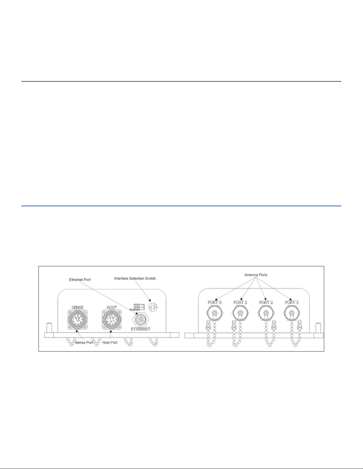
Figure 1 shows the four port version of the MPRX-FH. The host connector, sense connector, Ethernet
connector, and interface selection switch are on the opposite end of the MPRX-FH from the four antenna
port locations.
Figure 1 MPRX End Views
Power and Communications Cables
Cable length for power and communications depends on the physical characteristics of the MPRXFH installation site. Table 2 lists accessory kits available for cabling options based on your site’s
requirements.
TransCore Proprietary
1–19
Page 20

MPRX-FH User Guide
Electrical Power
Table 2 Connector Cabling Accessory Kits
Part Number Description
58-7200-001 MPRX-FH host connector leads 0.15m (6in)
58-7200-002 MPRX-FH host cable assembly 3m (120in)
58-7200-003 MPRX-FH host cable assembly 5m (200in)
58-7200-004 MPRX-FH host cable assembly 10m (400in)
58-7201-001 MPRX-FH sense connector leads 0.15m (6in)
58-7201-002 MPRX-FH sense cable assembly 3m (120in)
58-7201-003 MPRX-FH sense cable assembly 5m (200in)
58-7201-004 MPRX-FH sense cable assembly 10m (400in)
The MPRX-FH accepts 16-20VAC or 16-28VDC. Consult your local and national electrical codes for
installation and safety requirements.
It is the installer’s responsibility to supply conversion equipment and wiring. Table 3 contains power
supply current requirements.
Power circuits are protected internally against power surges (±30%).
Table 3 Power Supply Current Requirements
a
Standby
68°F (20°C)
Supply
(RF On)
a
Maximum
Power at 68°F (20°C)
(RF O)
Operating Power at
16 to 20V AC 20W (Watts) 14W
16 to 28 V DC 20W 14W
a 1700 milliamp (mA) initial rush-in current at startup
1–20
TransCore Proprietary
Page 21
Chapter 1 System Overview
Host Communications
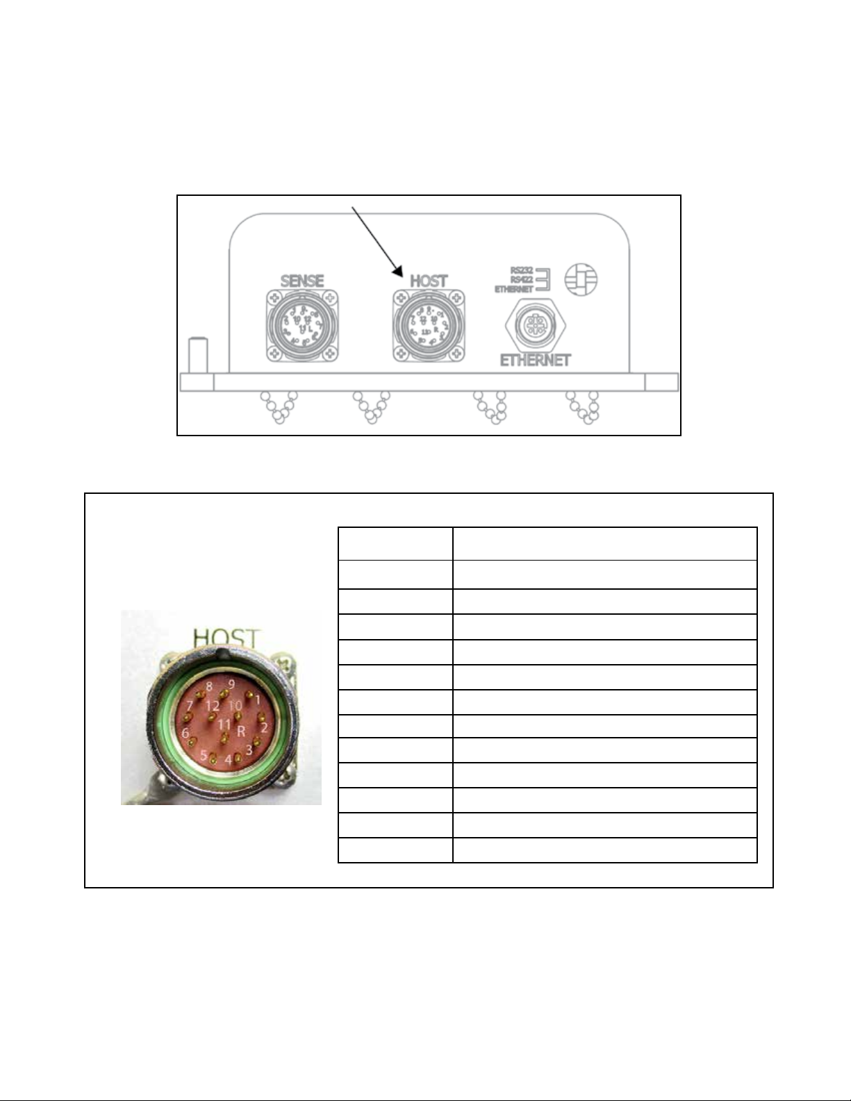
The MPRX-FH communicates through an asynchronous RS–232, RS–422, or Ethernet interface. Figure 2
shows the MPRX-FH communications ports and Figure 3 shows the host connector pin designations.
Figure 2 Location of Host Port on MPRX
Pin Number Operation
1
2
3
4
5
6
7 RS422_RX+
8
9
10
11 +V In
12 +V Return
RS232_TX
RS232_RX
LOCK
LOCK_RTN
RS422_TX+
RS422_TX–
RS422_RX–
COM_GND (RS232 GND)
COM_GND (RS422 GND)
Figure 3 Pin Assignments for Host Connector
The standard RS–232/RS–422/Ethernet connection maximum distance depends on the baud rate, cable
type, and the receiving device at the other end.
TransCore Proprietary
1–21
Page 22
MPRX-FH User Guide
Sense Connections
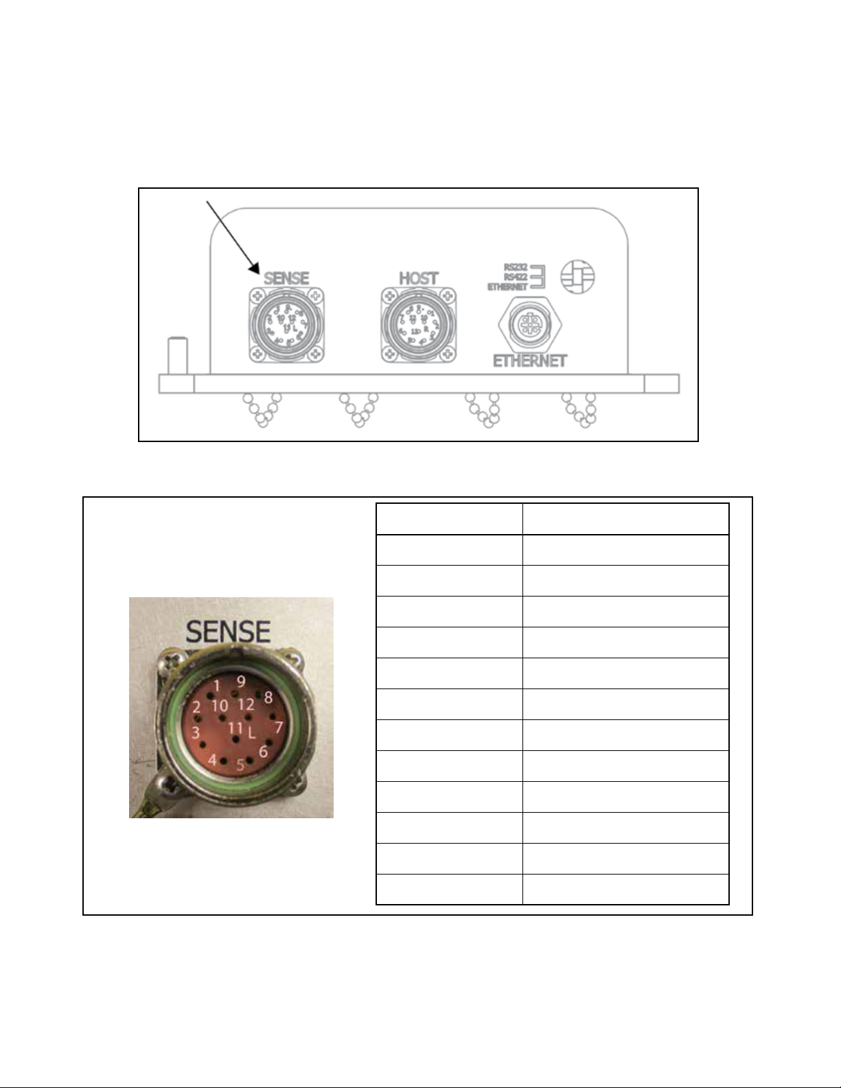
Figure 4 shows the location of the MPRX-FH sense port, and Figure 5 shows the sense connector socket
designations.
Figure 4 Location of Sense Port on MPRX
Socket Number Operation
1 +12VDC OUT
2 OUT1
3 I/O GROUND
4 I/O GROUND
5 PULSE OUT
6 OUT0
7 CTAG 0
8 CTAG 1
9 I/O GROUND
10 I/O GROUND
1–22
11 SENSE 1
12 SENSE 0
Figure 5 Socket Assignments for Sense Connector
TransCore Proprietary
Page 23
Chapter 1 System Overview
The MPRX-FH’s two RF sense input circuits are TTL (Logic Level, 0V/5V), designed to be shorted to I/O
Ground (0V) to provide sense presence detect for antenna ports 0 and 1 (Sense 0) and antenna ports 2
and 3 (Sense 1).
The MPRX-FH’s tag lock output circuit is a single-pole, double-throw relay providing a dry contact closure.
These contacts are rated at 42.2V AC peak (30V
The output circuit is not intended for the direct control of electro-mechanical devices such as motorized
barrier arms. For such applications, the MPRX-FH output circuit should be used to drive a secondary
appropriately-rated high-power relay.
) or 60V DC, at 1A maximum with non-inductive load.
rms
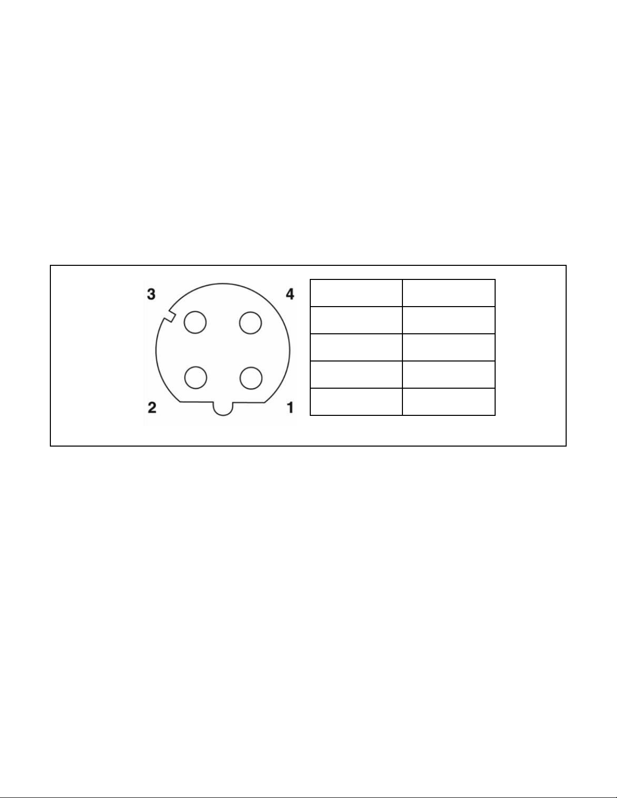
Ethernet Interface
The Ethernet interface is a standard M12 socket. Figure 6 shows the connector socket designation.
Socket Number Operation
1 Receive +
2 Transmit +
3 Receive -
4 Transmit -
Figure 6 Socket Assignments for Ethernet Connector
Antenna Interface
The site must include interface cable(s) between the MPRX-FH and the compatible antenna(s) chosen for
the site. The antenna interface is a reverse polarity TNC connector.
TransCore Proprietary
1–23
Page 24

MPRX-FH User Guide
Table 4 Recommended Cables
Cable Type
RG–223 0.216 12.8dB
RG–214 0.425 7.5dB
FSJ1–50 0.25 5.68dB
LDF2–50 0.375 11.01dB
FSJ4–50B 0.50 11.25dB
LDF4–50A 0.50 6.94dB
a Suxes 50, 50A, and 50B indicate 50-ohm cables available
from the Andrew Corporation.
Compatible Tag Types
The MPRX-FH provides the capability to read ISO/IEC 18000-63 formatted tags and TransCore Super eGo
(SeGo) protocol tags. Refer to “Compatible Tag Information” on page E–124 for information on compatible
tag models.
Overall
a
Diameter
(in.)
Cable Loss
per 100 ft
1–24
TransCore Proprietary
Page 25

Chapter2 Test Procedures
Required Tools and Equipment
Ensure that you have received all parts before beginning your pre-installation MPRX-FH tests.
Your MPRX-FH is packaged with the following materials:
• One MPRX-FH
• One MPRX-FH Quick Start Guide
• Any accessories ordered as options (refer to Table 5.)
Other required accessories are:
• Power/communications cable harness
• 16-20VAC or 16-28VDC
• At least one MPRX-FH-compatible antenna (refer to “Table 1 Approved Antenna List” on page iii)
Chapter 2 Test Procedures
• Antenna RF cable
These may be ordered as accessories from TransCore or obtained from other sources.
Additional Materials Needed for Testing
You will need these additional materials to perform the pretests on the MPRX-FH:
• Test tags, supplied by the TransCore dealer or distributor (formatted for ISO/IEC 18000-63 or SeGo)
• Suitable power wiring for the MPRX-FH (refer to “Table 1 Approved Antenna List” on page iii)
• Audible circuit tester and 9V DC battery for circuit tester power
• Wire stripper
• At least one MPRX-FH compatible antenna
• Suitable RF interface coaxial cable
TransCore Proprietary
2–25
Page 26

MPRX-FH User Guide
Pretest Accessory Options Available From TransCore
Table 5 lists optional TransCore MPRX-FH installation accessory items.
Part No. Description
58-7200-001 MPRX-FH Host Connector with Leads 0.15m (6in)
58-7200-002 MPRX-FH Host Cable 3m (120in)
58-7200-003 MPRX-FH Host Cable 5m (200in)
58-7200-004 MPRX-FH Host Cable 10m (400in)
58-7201-001 MPRX-FH Sense Connector with Leads 0.15m (6in)
58-7201-002 MPRX-FH Sense Cable 3m (120in)
58-7201-003 MPRX-FH Sense Cable 5m (200in)
58-7201-004 MPRX-FH Sense Cable 10m (400in)
20-7001-001 MPRX-FH check tag accessory kit
13-5118-903 Test Rail Tag with metal back plane – Rail-car Format – SeGo
13-5118-904 Test Rail Tag with metal back plane – Locomotive Format – SeGo
Table 5 Pretest Accessory Options
Table 6 lists pretest accessory options available from a third party.
Table 6 Pretest Accessory Options Available From Third Party
Mfg Part No. Mfr. Description
HG908P-NM LCOM 915 Mhz Bench Antenna – LCOM – 4 ft type N male connector
4N5W-03 AERO FLEX Type N attenuator 5 W – 3 db
4N5W-10 AERO FLEX Type N attenuator 5 W – 10 db
4N5W-15 AERO FLEX Type N attenuator 5 W – 15 db
3018-5W AERO FLEX Type N 50 ohm load – 5 W
2–26
TransCore Proprietary
Page 27
Pre-installation Testing of the MPRX-FH
9
VDC
Battery
6-12VDC
Buzzer
+ -
Pin 4 on
Host Connector
Pin 3 on
Host Connector
- +
Pretest involves the following steps:
• Testing the MPRX-FH circuit
• Connecting the antenna(s)
• Connecting the power supply
• Connecting communications
• Connecting sense input and sense output circuits
• Power and tag read capability testing prior to final installation of the MPRX-FH
Testing the MPRX-FH Circuit
Before installing the MPRX-FH permanently at the site, you should test the circuit to confirm that the MPRXFH has power and can read a tag that is in the tag read zone.
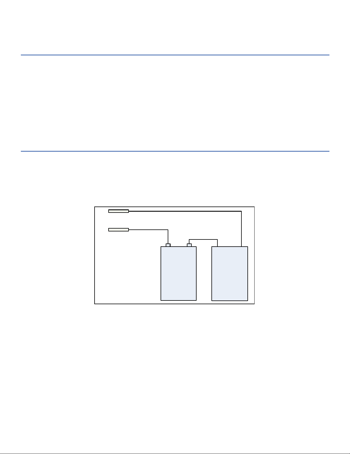
A voltage meter or audible circuit tester (buzzer) is necessary in order to test the circuit. An example test
setup diagram is shown in Figure 7. The buzzer is powered by a 9VDC battery and is equipped with two
alligator-clip leads. When you touch the leads together, the box will produce an audible sound.
Chapter 2 Test Procedures
Figure 7 Wiring for Audible Circuit Tester for MPRX-FH
TransCore Proprietary
2–27
Page 28
MPRX-FH User Guide
Connecting the Antenna(s)
To test the MPRX-FH, connect the antenna and power supply as described in this section.
Discharge Voltage from the Antenna
Caution
During shipping and installation, an antenna can build up a very high voltage charge.
The voltage needs to be discharged before connecting the antenna to the reader.
TransCore strongly advises that you use adequate Earth Ground for this voltage
discharge procedure in accordance with the National Electric Code for the locale where you are
installing the MPRX-FH.
Use these instructions to discharge high voltage from the antenna before proceeding with further
pre-installation testing of the reader.
Required Equipment
This procedure requires the following equipment.
• MPRX-FH
• External antenna
• Grounding RF cable (long enough to reach Earth Ground source)
• N-type load (e.g., 50 Ω) or RF attenuator (e.g., 20 dB)
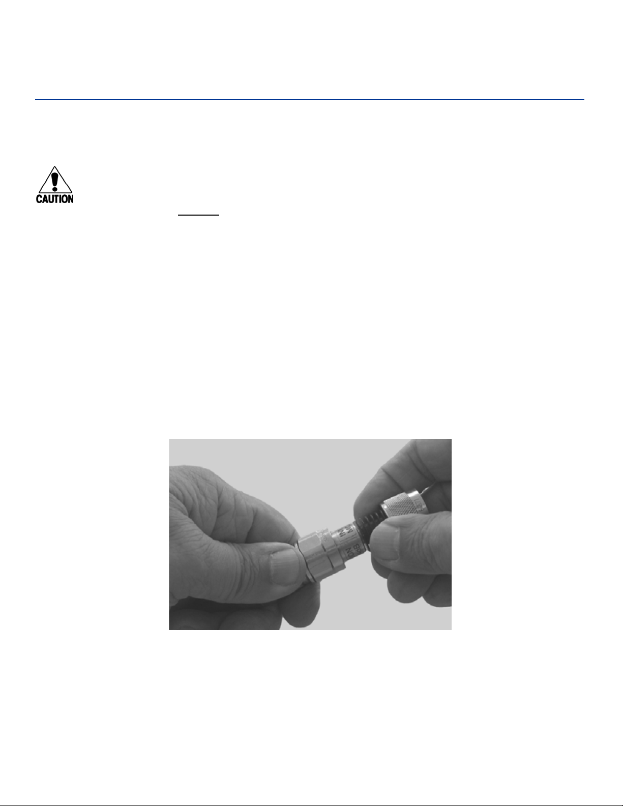
1. Terminate the reader end of the grounding RF cable with any N-type load or RF attenuator
(Figure 8).
2–28
Figure 8 Connect RF N-type Load or Attenuator to Reader Cable End
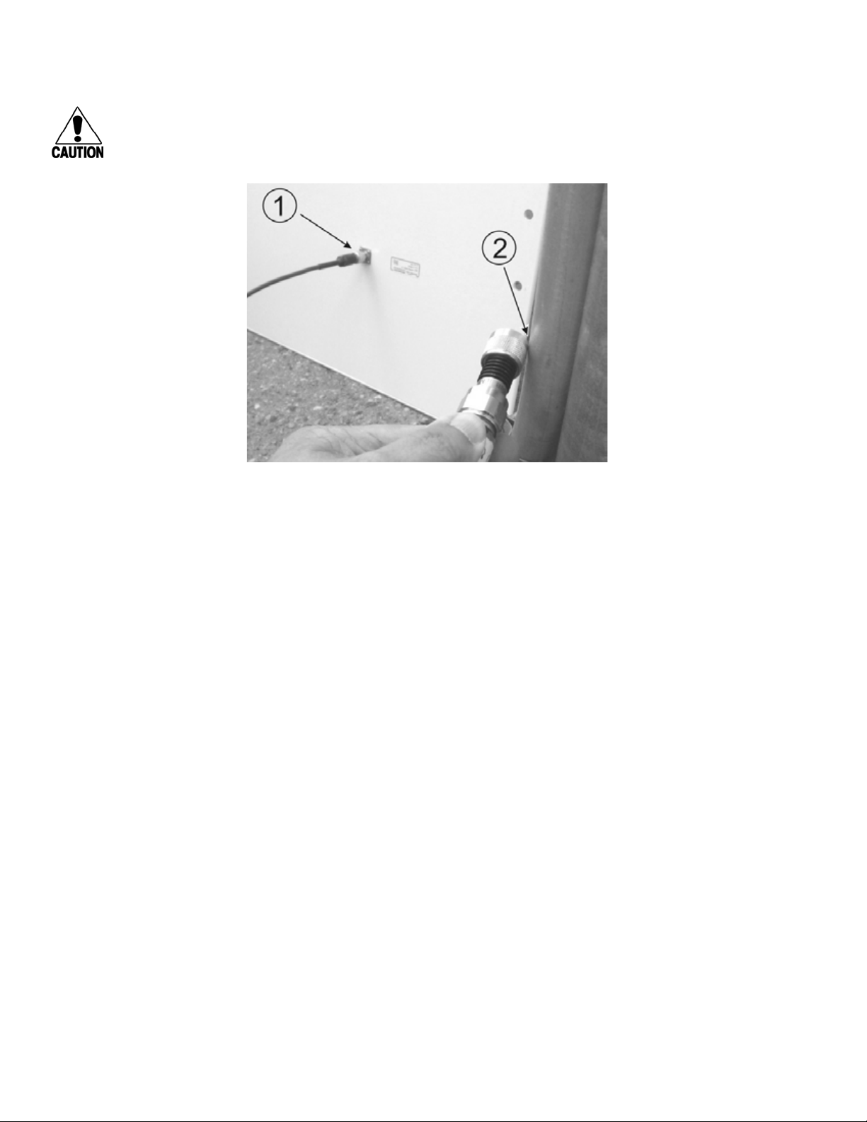
2. Connect the grounding RF cable to the antenna (Item 1 in Figure 9).
3. Short the outer metal case of the load or attenuator to Earth Ground for approximately 10 seconds
(Item 2 in Figure 9). In this example, the operator is using the mounting pole that has been
properly connected to Earth Ground.
TransCore Proprietary
Page 29
Chapter 2 Test Procedures
CAUTION
TransCore does not recommend using a screwdriver or other tool to short the RF cable center
conductor to the outer ground of the cable. This grounding method can damage the center pin
or the threads of the connector.
Figure 9 Short Load to Earth Ground
4. Disconnect the grounding RF cable from the antenna and connect the permanent RF cable to
reader.
Once the antenna is discharged and properly connected to the reader, the reader circuitry
provides a DC path to keep any further charge from building up in the antenna.
TransCore Proprietary
2–29
Page 30
MPRX-FH User Guide
Connecting the Reader and Antenna
1. Ensure the reader is turned o and power is disconnected.
2. Connect one end of the RF interface cable to the antenna.
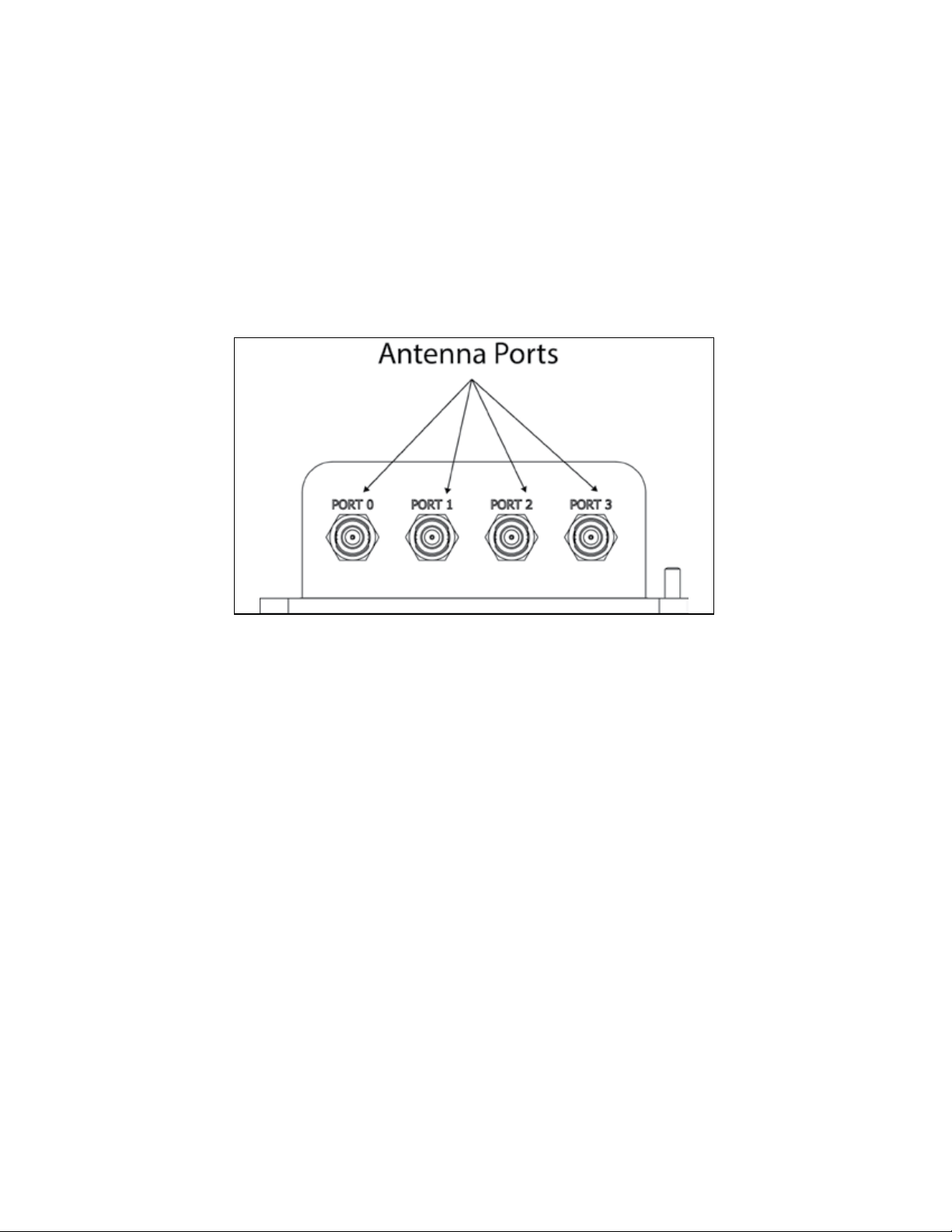
3. Connect the other end of the RF interface cable to the appropriate antenna port on the end of the
MPRX-FH. Refer to Figure 10.
4. The ports can be turned on in consecutive order. If all four ports will not be used, start with Port 0
and turn on connected ports. Unused ports should be set to OFF. Refer to “Numerical Command
List” on page D–113 for a list of commands.
Figure 10 MPRX-FH Showing Antenna Ports
2–30
TransCore Proprietary
Page 31

Connecting the Power Supply
Caution
To avoid damage to the MPRX-FH, first connect the reader to Earth Ground using a
ground cable and stake before powering up the reader or connecting to an antenna.
TransCore recommends following the National Electric Code or equivalent code for surge
protection for the locale where the MPRX-FH is installed. A minimum of 18 AWG wire to earth
ground is required for protective earthing.
Connect any antenna(s) or terminate the antenna ports before applying power to the reader.
Connect the MPRX-FH to a Power Supply
1. Connect the MPRX-FH to Earth Ground. Figure 11 shows the location of the MPRX-FH ground stud.
Chapter 2 Test Procedures
Figure 11 Location of MPRX-FH Ground Stud
TransCore Proprietary
2–31
Page 32

MPRX-FH User Guide
2. Connect the MPRX-FH to a power supply using the host interface cable.
The Sense and Host ports on the MPRX-FH are M23 connectors (Figure 12). Table 7 lists the pin
assignments for the Host connector and Table 8 lists the socket assignments for the Sense
connector.
Figure 12 Location of Host/Sense Ports on MPRX-FH
Table 7 Pin Assignments for Host Connector
Pin Number Operation
1 RS232_TX
2 RS232_RX
3 LOCK
4 LOCK_RTN
5 RS422_TX+
6 RS422_TX–
7 RS422_RX+
8 RS422_RX–
9 COM_GND (RS232 GND)
10 COM_GND (RS422 GND)
11 +V In
12 +V Return
2–32
TransCore Proprietary
Page 33

Table 8 Socket Assignments for Sense Connector
Socket Number Operation
1 +12VDC OUT
2 OUT1
3 I/O GROUND
4 I/O GROUND
5 PULSE OUT
6 OUT0
7 CTAG 0
8 CTAG 1
9 I/O GROUND
10 I/O GROUND
11 SENSE 1
Chapter 2 Test Procedures
12 SENSE 0
Connect the Power Supply
After mounting the MPRX-FH, connect the reader to a dedicated 16–28VDC or 16–20VDC power supply.
The MPRX-FH should be connected to power with an external fuse to protect both the MPRX-FH and
power source. Inrush and Steady State currents for the MPRX-FH are listed in Table 9. Choice of fuse type
and rating shall comply with regulatory requirements of the installation.
Table 9 Inrush and Steady State Currents for MPRX-FH
MPRX-FH Current
Voltage (VDC) Inrush Current (A) Inrush Time (ms)
12 4.89 1.38 1.68
24 9.4 2.46 0.87
Caution
To avoid damage to the MPRX-FH, connect the MPRX-FH to ground before powering up
the reader or connecting the antenna(s).
Connect the antenna(s) before applying power to the reader.
Steady State
Current (A)
TransCore Proprietary
2–33
Page 34

MPRX-FH User Guide
Interface Selection Switch
The MPRX-FH incorporates a communications interface selection switch, which allows on-the-fly changes
to the communications mode. This switch allows selecting the reader’s receive communications interface.
All communications interfaces are configured for simultaneous transmit, but only the interface selected by
the switch is active for commands transmitted into the reader.
Connecting Communications
The MPRX-FH communicates through RS–232, RS–422, or Ethernet protocols.
Required Materials
You need the following materials to connect the communications cable to the host device:
• Host device
• Any terminal emulation program operating on a PC
Connecting the MPRX-FH to the Host Port
MPRX-FH communications and customer interface signals are supplied from the MPRX-FH to the host
through a multi-wire cable. The connector for this cable is located on the end of the MPRX-FH (Figure 12
on page 2–32).
Insert one end of the MPRX-FH communications/power interface connector into the M23 Host connector
at the MPRX-FH and the other end into the customer-supplied host device connector. Refer to Table 7 and
Table 8 for pin assignments and numbers.
Connecting Sense Input and Sense Output Circuits
The MPRX-FH has two sense input circuits and a tag lock output circuit available. SENSE 0 is used to
enable RF on antenna ports 0 and 1 if enabled, and SENSE 1 is used to enable RF on antenna ports 2
and 3. The sense input circuits are used to notify the MPRX-FH of train presence and are designed to be
connected to a free-of-voltage dry contact. The tag lock output circuit is a single-pole, double-throw relay
that provides a normally closed and normally open dry contact. The relay contact is rated at 42.2VAC peak
(30 Vrms) or 60VDC at 1 A maximum.
CAUTION
If controlling an external gate or device requiring high current, an isolation transformer
is required.
Sense Input Circuits
2–34
The MPRX-FH supports two sense inputs – SENSE 0 and SENSE 1 – which require two sense input lines
(SENSE x and GND) for each loop sense or a total of four sense input connections. SENSE 0 is used to
control RF power for the track that has antennas connected to RF ports 0 and 1. The sense inputs are
wired through the reader M23 sense connector. The MPRX-FH expects the SENSE 0 circuit to close when
a rail car is present (on the track with antennas connected to MPRX-FH ports 0 and 1).
TransCore Proprietary
Page 35

Chapter 2 Test Procedures
SENSE 1 must be closed when a rail car is present on the track connected to MPRX-FH antenna ports 2
and 3. The reader RF switches on to the appropriate RF ports immediately upon detecting SENSE x.
Sense Output Circuit
The sense output is dedicated for testing and reader setup. It is defined as the TAG_LOCK signal, which
indicates a valid tag is in the read field.
This sense output is a dry contact that provides a normally open and normally closed sense output. The
relay contacts are rated at 42.2VAC peak (30 Vrms) or 60VDC at 1A maximum. If controlling an external
gate or device requiring high current, an isolation transformer is required.
Interface through Ethernet Port
To interface through the Ethernet port of the MPRX-FH, connect via the M12 Ethernet port (Use an M12
to RJ45 adapter if required). A static IP address will need to be assigned to the local host if directly
connected, or the reader may be attached to the network.
Setting up Local Host
1. From the following link, install the stand-alone DeviceInstaller. (Refer to Figure 13.) This is needed
to know the IP address of the Ethernet to serial converter.
http://ltxfaq.custhelp.com/app/answers/detail/a_id/644?_ga=1.59440430.2035039615.1475511776
Figure 13 Stand-alone DeviceInstaller Link
2. Once installed, launch DeviceInstaller from the START menu (Figure 14).
Figure 14 DeviceInstaller Start Menu
3. Select whether to direct-connect to the computer Ethernet port or whether to connect to the
corporate network.
TransCore Proprietary
2–35
Page 36

MPRX-FH User Guide
Connecting Directly to Computer Ethernet Port
1. Go to the computer’s network setting and change the IP address and Subnet mask of the network
interface controller (NIC) card you are connecting to as shown in Figure 15.
Figure 15 Connecting Directly to Computer Ethernet Port
2. If the computer has multiple NIC cards, a prompt may appear as shown in Figure 16. Select YES.
Figure 16 Multiple NIC Cards
3. At the next prompt, choose the desired adapter (Figure 17). If necessary, the selection can be
changed at a later time through the OPTIONS menu.
2–36
Figure 17 Adapter Options
TransCore Proprietary
Page 37

Chapter 2 Test Procedures
For the direct-connect to the computer’s Ethernet port option, choose the network adapter with
the 169.254.10.1 address.
To connect to the corporate network, choose the Local Area Connection.
4. The next screen prompts for an update (Figure 18). Select NO.
Figure 18 Check for Updates Screen
Finding the IP Address of the Reader
Note: If a firewall is present it will need to be disabled to allow access (Figure 19).
Figure 19 Disable Firewall
TransCore Proprietary
2–37
Page 38

MPRX-FH User Guide
1. From the Lantronix DeviceInstaller, right-click on the appropriate connection and select refresh
(Figure 20).
Figure 20 LanTronix DeviceInstaller Screen
2. The Xport Direct+ device will populate on the right side of the window (Figure 21). Use the IP
address to configure your terminal emulator connection. Use Telnet and Port 10001.
3. The opened connection works just like a serial connection.
Figure 21 Xport Direct+ Device Screen
2–38
TransCore Proprietary
Page 39

Chapter 3 General Software Information
Chapter3 General Software Information
Command Entry Conventions
All MPRX-FH commands are preceded by the start-of-message character (#). The end-of-message
sequence expected from the host is a carriage return (CR). The MPRX-FH terminates messages with a
return and a line-feed (CR/LF). For example, the command #01 Switch To Command Mode is typed as
follows:
#01<ENTER>
where
<ENTER> is the Enter or Return key.
Some command characters may be represented by the letter N. This letter indicates you are to supply a
value. Maximum valid entries are the numbers 0 through 9 and the uppercase letters A through F. These
letters allow for as many as 16 available user responses and are based on the hexadecimal numbering
system.
Commands have at least two characters following the # character. Table 10 shows the basic structure of a
four-character command.
Table 10 Four-Character Command Structure
#1005 Set Baud Rate To 9600 Baud
# All commands are preceded by the # character.
Indicates the command group. This command is in Group 1 –
1
Communications Port Control.
Indicates the command subgroup. In this example, all commands
0
with a second digit of 0 apply to the main port.
The command digit. In this example, the 0 indicates that this
0
command aects the baud rate.
Indicates the setting. Normally this is a variable and is usually a
hexadecimal value from 0 through F. In this example, 5 sets the
5
baud rate to 9600, the factory setting. In some commands, this
digit may be a four-place hexadecimal string or a character string.
Command Response Conventions
Like the MPRX-FH commands, responses are preceded by the # character. Many MPRX-FH commands
respond with #Done or #Error indicating the command was or was not recognized and completed.
Other commands respond with a four-character identifier followed by one or more values.
TransCore Proprietary
3–39
Page 40

MPRX-FH User Guide
Table 11 shows an example of a command/reply sequence. This example assumes that an MPRX-FH with
serial number SN97001P running version X.XX software is connected to a PC running a terminal emulation
software package. The command sequence verifies that communications are working correctly.
Table 11 Sample Command Sequence
Entry MPRX-FH Response
#01 <CR> #Done <CR/LF>
#505 <CR>
#00 <CR> #Done <CR/LF>
In command discussions, MPRX-FH response characters may be shown in brackets < >. The use of
brackets indicates that the response is a value in the range of characters. The brackets are not part of the
response. For example, the response to command #520 Display Power Fail Bit is either a 0 or a
1. In the command discussion, the response is shown as:
#PWRB <0-1>
with actual MPRX-FH response being one of the following:
#PWRB 0
#PWRB 1
In this example, PWRB is the four-character identifier for power fail bit, and the 0 or 1 is the value. All spaces
shown in the response are actual spaces sent from the MPRX-FH. In this example, one space is between
the letter B and the number.
#Model E4 Series Ver X.XX
SN97001P <CR/LF>
Switches MPRX-FH to
command mode
Reports the software
version and serial
number
Returns MPRX-FH to
data mode
Notes
Operating Parameters
The MPRX-FH maintains its operating parameters in nonvolatile memory (NVRAM) so that the parameters
are preserved after a power-down sequence.
Power Fail
The system maintains a power fail flag. The host transmits command #520 Display Power Fail Bit to
determine if a power down has occurred. This flag is cleared by both command #63 Reset Reader and
command #65 Reset Power Fail Bit.
Program Download
Program Download stores the MPRX-FH application software into the reader’s flash memory. It is used to
install program upgrades, add features, and to recover from corrupted program data.
Note: Program Download is a custom TransCore utility host process.
3–40
TransCore Proprietary
Page 41

Chapter 3 General Software Information
Download Considerations
You should consider the following factors when performing Program Download:
• The MPRX-FH does not process tags while in download mode.
• The MPRX-FH does not accept any program data unless a successful erase of flash memory
has been performed before transmitting the data. Erasing the flash memory typically takes two
seconds.
• Cycling reader power after exiting from download mode re-executes startup. If the new software
has been loaded without errors, the MPRX-FH comes up in data mode. If a flash checksum error
is detected, the MPRX-FH reenters download mode and transmits a sign-on message with a boot
version of 0.00x and without a serial number.
Note: The MPRX-FH uses default boot communications parameters when operating in download
– 38400 baud, 8 data bits, 1 stop bit, no parity, basic protocol – and does not echo
mode
commands.
Download Procedures
If TransCore releases a new version of the MPRX-FH software or if the MPRX-FH does not appear to be
working properly, you may need to download the software to the MPRX-FH. Contact technical support or
your TransCore sales representative.
Startup
Upon startup, MPRX-FH transmits a sign-on message or a boot ROM failure message.
Sign-On Message
If startup is successful, the sign-on message appears as follows:
where
Serial number 000000 is the default setting and is not a valid number. If this number appears in the
sign-on message, the serial number has never been stored into reader memory. The serial number must
be assigned by factory-authorized personnel using command #695S...S Set Serial Number.
Because only six digits are allowed in the software, when setting the serial number skip the fourth (middle)
digit of the seven-digit number shown on the reader label.
Model E4 Series [software version] SNSSSSSS
[Copyright notice]
SSSSSS is the serial number assigned to the MPRX-FH unit being used.
If the flash memory checksum does not indicate verification, the sign-on message appears as follows at a
baud rate fixed at 38,400 bps:
Model [E4] Ver 0.00x
[Copyright notice]
TransCore Proprietary
3–41
Page 42

MPRX-FH User Guide
Boot Failure Message
Upon powering up, the software performs a checksum verification on itself. The function returns a specific
value for the particular version of software. If the value returned is not correct, the boot code assumes that
the application code has been corrupted and a failure condition exists. If the failure message does not
transmit, a communications error has occurred or the boot has failed to the extent that it cannot transmit the
failure message.
If the failure message version number equals 0.00 and no serial number exists, the flash memory
checksum has failed, and the MPRX-FH is operating out of boot ROM. In this case, the MPRX-FH
automatically enters download mode and waits for a new program to be loaded into the flash memory.
Contact TransCore Technical Support for assistance.
Tag/Message Buer
The MPRX-FH maintains a tag buer in battery backed RAM to save tag IDs acquired when data inquiry
protocol is used. This buer holds up to 500 time-stamped messages.
Note: When the buer fills, subsequent tag IDs will be lost.
3–42
TransCore Proprietary
Page 43

Chapter 4 Communications Protocols
Chapter4Communications Protocols
Introduction
The MPRX-FH supports the following communications protocols:
• Basic
• Error correcting
• Data inquiry
The following protocol information provides reference information relevant to developing host software.
Communications are performed using the 7-bit ASCII code with optional parity, providing easy setup,
testing, and diagnostics with standard ASCII terminals and serial printers.
Each message is framed within the start-of-message <som> and end-of-message <eom> characters
so that the host device can detect the beginning and end of each message. This convention is most
important under marginal communications conditions during which the host may receive extraneous noiseinduced characters between reader transmissions. In such instances, the host is capable of ignoring any
messages that do not conform to the <som>...<eom> frame sequence.
Both data mode and command mode require a two-way message interchange when using error
correcting protocol (ECP). This interchange is completed by the message recipient returning a message
acknowledgment to the message sender.
With ECP, all transmissions require a message. If a message is not received, the sender will time out with
the same eect as if it had received a negative acknowledgment (from the host) or an #Error message
from the MPRX-FH.
Software (XON/XOFF) flow control is optionally supported. Be careful in the use of XON/XOFF since noiseinduced characters may be interpreted by the MPRX-FH as the XOFF character, which would suspend
reader output without information reaching the host device. For more information, refer to “Reader
Transmissions” on page 4–45.
Note: TransCore recommends that XON/XOFF flow control be disabled while using ECP.
TransCore Proprietary
4–43
Page 44

MPRX-FH User Guide
Basic Protocol
With basic protocol, messages sent to and from the MPRX-FH and the host are transmitted without error
checking. For each host transmission, the MPRX-FH returns a #Done or #Error message to the host.
When the host device is physically close to the MPRX-FH and no sources of interference exist, the basic
protocol provides reliable communications.
The host must be ready to receive reader-transmitted messages because in basic protocol the MPRX-FH
does not wait for the host to acknowledge a message before transmitting the next message. If necessary,
the host may halt reader transmissions by using software flow control. Refer to “Chapter 6 Configuration”
on page 6–84 for software flow control information.
Error Correcting Protocol
When the quality of data communications is imperative or may be suspect, you can utilize ECP to ensure
the integrity of data transmitted between the MPRX-FH and the host.
Note: TransCore recommends that basic protocol (not ECP) be used when commands are entered
manually at the keyboard.
Error correction is accomplished with the use of a cyclic redundancy check (CRC) value that is based on
the message data. The originator (reader or host) calculates the CRC value of a message and includes it in
the transmitted message.
The recipient (reader or host) also calculates a CRC value for the received message. If the transmitted
message data is correct, the CRC value calculated by the recipient will agree with the CRC value
calculated by the originator. If the CRC values do not agree, the recipient rejects the message.
Message sequence numbers are also included when using ECP. These sequence numbers are checked
to determine if the message received has the correct sequence number; if not, the recipient rejects the
message.
Because the seven-bit ASCII code is used and there are eight data bits per character, the eighth bit can
optionally be used to support parity. Where parity is selected, the CRC value calculation includes the parity
of each character in the calculation of the CRC value.
Parity is required to achieve the most reliable communications. If parity is enabled, both the MPRX-FH and
the host must issue a message if any received character has a parity error. However, the message must
not be transmitted before receipt of the <eom> character. If the message is transmitted prematurely, the
MPRX-FH will issue an #Error message, and the host device will issue a negative acknowledgment
message.
4–44
TransCore Proprietary
Page 45

Data Inquiry Protocol
Data inquiry protocol is a basic protocol option that allows the host to control transmission of reader tag
data. The selection of data inquiry protocol aects data mode operation. As MPRX-FH acquires tags, it
buers them but does not transmit them. Instead, the host must poll MPRX-FH for each tag by sending a
CTRL-E character (hex 5 digit). MPRX-FH transmits one message (tag ID or report data) for each CTRL-E it
receives until the buer is empty.
Each tag request message sent by the host consists only of the CTRL-E character; no <som> or <eom>
characters are sent. MPRX-FH data transmission (tag ID and report data) format is the same as for basic
protocol.
Selection of data inquiry protocol does not aect command mode operation.
Basic Protocol and ECP Format
Note: In the following text, the symbols <and> are used to represent required variable message
data, and the symbols [and] are used to represent optional data. These symbols are not part of the
message syntax.
Chapter 4 Communications Protocols
Reader Transmissions
The basic protocol format and the data inquiry protocol format are as follows:
<som><data><eom>
The ECP format is as follows:
<som><seq><data><crc><eom>
where
<som> Start-of-message (ASCII # character)
<seq> Sequence number (ASCII hex) that represents an even number in the range 0–9, A–F
(0, 2, 4, 6, 8, A, C, E). The MPRX-FH maintains the number. The host must acknowledge
reader transmissions by sending an ACK message with the same sequence number
received from the MPRX-FH. The MPRX-FH updates its sequence number upon receipt
of a valid host ACK. If an ACK is not received, the MPRX-FH retransmits the message.
A reader transmission sequence is not considered complete until the MPRX-FH
receives an ACK and updates its sequence number.
<data> ASCII string up to 72 characters long. This string may contain tag data; a presence
without tag report; an input status change report; an #Error06, #Error07,
#Error08, or #Error11 message; or a sign-on message. Auxiliary data may also be
included.
<crc> Field containing four ASCII digits that represent the 16-bit CRC value calculated on the
message. The CRC value is calculated on bytes between the <som> character and the
first <crc> byte.
TransCore Proprietary
4–45
Page 46

MPRX-FH User Guide
When the host receives a properly framed message, it can calculate a 16-bit CRC value.
The calculation is applied to the character string that immediately follows the <som>
and that ends with the character immediately preceding the first <crc> character.
Transmitted CRC value can then be compared with the binary equivalent of the
received <crc> characters. If the transmitted and received CRC values do not
match, the recipient assumes the message was received in error, and transmits a NAK
message response.
<eom>
End-of-message characters (ASCII CR and LF). The system includes both a carriage
return (CR) and line feed (LF) to facilitate the use of terminals and printers.
If the host receives a <som> character in the middle of a data message, the message in
progress is aborted. The assumption is that an <eom> was lost and the MPRX-FH is in
the process of retransmitting the previous message.
ECP Host ACK/NAK Response
With ECP, the host device responds to all data message transmissions from the MPRX-FH using the
following acknowledgment or negative acknowledgment response format.
<som><seq><ack/nak><crc><eom>
where
<som> Start-of-message (ASCII # character)
<seq> Echo of the sequence number received from the MPRX-FH. The sequence number
should correspond to the data message that is being positively or negatively
acknowledged by the host. If the MPRX-FH receives an ACK message with the
incorrect sequence number, the data message is retransmitted.
The host device resets the anticipated data message sequence number to that of the
MPRX-FH before communications can resume without error.
4–46
<ack/nak> ASCII @ character for ACK response; ASCII ? character for NAK response
<crc> CRC value for the message
<eom> End-of-message character (ASCII CR)
The MPRX-FH sets a user-programmable timeout delay at the time each message is transmitted based
on command #612NN Set Error Correcting Protocol Timeout, where NN = timeout delay. To disable the
timeout delay for diagnostic purposes, issue the command #612FF Disable Error Correcting Protocol
Timeout.
If the timeout delay expires before the MPRX-FH receives an ACK or NAK message from the host, a logical
NAK condition will be declared. If the MPRX-FH receives a NAK or timeout, the reader retransmits the data
message.
When the MPRX-FH receives an ACK message, the system software treats the message as having been
properly received by the host. The software increments the sequence number, and advances pointers to
the next message in the MPRX-FH’s message queue to prepare for sending the next message.
TransCore Proprietary
Page 47

Chapter 4 Communications Protocols
Switch to Command Mode Request
The host device may issue command #01 Switch to Command Mode while in data mode.
The basic protocol format is as follows:
<som><cmd><eom>
The ECP format is as follows:
<som><seq><cmd><crc><eom>
where
<som> Start-of-message (ASCII # character)
<seq> Sequence number generated by the host device separately from that appearing in data
messages transmitted by the MPRX-FH
<cmd> Switch to command mode (ASCII characters 01)
<crc> CRC value for the message
<eom> End-of-message character (ASCII CR)
Host Transmission
The host device initiates synchronous communications between the MPRX-FH and the host. The host
begins a sequence by issuing a command; the MPRX-FH responds accordingly.
The data inquiry protocol format is as follows:
<CTRL-E>
The basic protocol format is as follows:
<som><cmd>[<data>]<eom>
The ECP format is as follows:
<som><seq><cmd>[<data>]<crc><eom>
where
<CTRL-E> ASCII Control E (hex 5 digit). When in data inquiry mode, each
<CTRL-E> by the host causes the MPRX-FH to transmit one tag ID.
<som> Start-of-message (ASCII # character)
<seq> Sequence number (ASCII hex digit) that represents an odd number in the range 0–9,
A–F (1, 3, 5, 7, 9, B, D, F). The host should use odd sequence numbers in its command
since the MPRX-FH uses even sequence numbers in its transmissions. This method
eliminates the possibility of a synchronous host command and an asynchronous reader
transmission having the same sequence number.
transmission of a
Upon receiving a host command in ECP, the MPRX-FH replies using the command’s
sequence number in its response. Therefore, the host device updates its sequence
number upon receipt of a valid reader response. If the sequence number is not
updated before transmission of the next command, the MPRX-FH will not service the
new command; it will retransmit its previous message. A command/message sequence
is not complete until the host updates its sequence number.
TransCore Proprietary
4–47
Page 48

MPRX-FH User Guide
<cmd> Command code, a string that contains from two to four ASCII hex characters
[<data>] Optional data field, an ASCII string of as many as 20 characters
<crc> CRC value for the message
<eom> End-of-message character (ASCII CR)
Reader Command Response
The basic protocol format is
The ECP format is
where
in length. For example,
the store hardware configuration string command is #696S...S or command #696
Store Hardware Configuration String followed by the data string S...S.
<som><resp><eom>
<som><seq><resp><crc><eom>
<som> Start-of-message (ASCII # character)
<seq> Echo of sequence number received in host command message
<resp> Response string. The MPRX-FH returns #Done, #Error, or another
depending on the host transmission. This string can be up to 72 characters long.
<crc> CRC value for the message
<eom> End-of-message character (ASCII CR and LF)
ASCII string
Sample Messages
This section contains examples of typical messages transmitted between the MPRX-FH and the host
device.
Reader Transmissions
Basic protocol reader transmission
#KING 1302<eom>
Host response
No host response for non-ECP
ECP reader transmission
#4KING 1302 <crc><eom>
4–48
TransCore Proprietary
Page 49

where
Chapter 4 Communications Protocols
#
4
KING 1302 Message data: Tag ID is shown.
<crc> CRC value for the message
<eom> End-of-message character
Host response
where
# Start-of-message character
4 Message sequence number
@ ACK (acknowledgment character)
? NAK (negative acknowledgment character)
<crc> CRC value for the message
<eom> End-of-message character
Start-of-message character
Message sequence number
Other sample message data could be as follows:
IOST C0 O2 I0 D24 (display I/O status) #Error06 (frequency not set)
#4@<crc><eom>
Host Command Transmissions
ECP host transmission
#7NNNXXX<crc><eom>
where
# Start-of-message character
7 Message sequence number
NNNXXX Select RF Operating Frequency command where NNN is the command and XXX is a
hexadecimal value from 000 to 118.
<crc> CRC value for the message
<eom> End-of-message character
#Done Command has been invoked by the MPRX-FH
Reader response
#7Done<crc><eom> or #7Error<eom>
For some commands, the MPRX-FH responds with data that relates to the command,
such as T0F 0, to indicate the mode enabled for a #570 Display Operating Mode
Status command.
#7Error<eom> will be returned if host transmission is not a legal command with legal
data.
TransCore Proprietary
4–49
Page 50

MPRX-FH User Guide
Timing and Synchronization
The ECP is largely independent of baud rate. The timeout delays previously described are a function of
baud rate.
The MPRX-FH supports an ECP timeout, which applies equally to both transmit and receive.
The receiver’s minimum timeout delay equals the time to transmit/receive the longest anticipated message
at the current baud rate setting. Additional margin should be included for idle periods between characters;
for example, processing overhead, if any. The timeout delay period can be expressed as follows:
where
rec (ms) = L x [Τchar + Τidle]
Τ
char (ms) 1000 x [ B
Τ
Bc
Rb
L
idle Maximum idle period between characters (ms)
Τ
Bits per character, typically 10
Baud rate, 1200–38.4 K
Length of message in characters
/ Rb ]
c
Note: The MPRX-FH supports baud rates between 1200 and 38.4 K.
Likewise, the sender must set a timeout delay equal to the delay of nine characters at the current baud
rate setting. For example, the time required to shift out the <eom> character plus the time to shift in the
ACK or NAK message to be received plus a processing allowance for the receiver to process the message
and check for error conditions.
Thus, the sending timeout delay can be expressed as follows:
send (ms) = 9 * Τchar + Τerrchk
Τ
where
errchk(ms) Processing period to perform error checking by receiver
Τ
The host device can remotely set the MPRX-FH’s communications parameters while in the command
mode, but TransCore does not recommend this action if communications conditions are marginal.
After the MPRX-FH receives new communications parameters, the MPRX-FH issues the #Done message
and switches to the new configuration immediately. The host device switches its communications
parameters immediately after the transaction is complete.
4–50
As noted, the message initiator, such as the MPRX-FH in data mode and the host device in command
mode, starts a timeout counter at the time a message is transmitted. If the timeout expires before receiving
an acknowledgment message, a logical NAK condition is declared, and the initiator assumes the message
was received in error. In this instance, the message is retransmitted until an acknowledgment message is
received.
The message recipient, such as the host device in data mode and the MPRX-FH in command mode, starts
a timeout counter when a <som> character is received. If the timeout expires without the receipt of an
<eom>, the message acquisition is aborted (reset), and the receiver waits for the next <som> character.
TransCore Proprietary
Page 51

Chapter 4 Communications Protocols
If the message recipient receives a second <som> character before an <eom> character, the message
acquisition is aborted (reset), and retransmission of the previous message is assumed to be underway.
These strategies allow for recovery during periods when communications are marginal or lost completely.
Reader-Addressed Failure Conditions
The MPRX-FH addresses the following failure conditions.
Illegal Sequence Number (Not in the Range 0–9, A–F)
If the MPRX-FH detects an illegal sequence number in a host command message, it discards the received
message and sends no response. If it receives an illegal sequence number in an ACK message, it
responds as if a NAK had been received and retransmits the data.
Wrong Sequence Number
If the MPRX-FH receives the wrong sequence number in an ACK message, it responds as if a NAK had
been received, and it retransmits the data.
Incorrect CRC
If the MPRX-FH detects an incorrect CRC value in a host command message, it discards the received
message. No response is sent. If it receives an incorrect CRC value in an ACK message, it responds as if a
NAK had been received, and it retransmits the data.
Illegal Command
If the MPRX-FH receives an illegal command, it returns its standard #Error message.
Transmission Timeout
If the MPRX-FH transmits an asynchronous message and the host does not send an ACK before the ECP
timeout occurs, the MPRX-FH retransmits the message.
Receive Timeout
If the MPRX-FH receives a <som> but does not receive a matching <eom> before the ECP timeout occurs,
it discards the incomplete message and resets its receiver.
Asynchronous Message/Command Message Collision
If the MPRX-FH transmits asynchronous data at the same time that the host sends a command, the MPRXFH gives priority to receiving the command. It processes the command and sends a message before it
retransmits the asynchronous data.
Host-Addressed Failure Conditions
The host device addresses the following failure conditions.
Illegal or Wrong Sequence Number
If the host detects an illegal or wrong sequence number in a reader response, it retransmits the command
with the same sequence number. If the host detects an illegal sequence number in an asynchronous
reader transmission, it sends a NAK message.
TransCore Proprietary
4–51
Page 52

MPRX-FH User Guide
Incorrect CRC
If the host detects an incorrect CRC value in a reader message, it retransmits the command with the same
sequence number. If the host detects an incorrect CRC value in an asynchronous reader transmission, it
transmits a NAK message.
Transmission Timeout
If the MPRX-FH does not respond to a host command within a specified interval, the host software
retransmits the command with the same sequence number.
Receive Timeout
If the host receives a <som> but does not receive a matching <eom> within a specified timeout interval, it
discards the incomplete message and resets its receiver.
Asynchronous Message/Command Message Collision
If the host receives an asynchronous reader transmission at the same time it transmits a command, it
ignores the asynchronous message and waits for the MPRX-FH’s response. The MPRX-FH retransmits
asynchronous data after it transmits the command message.
ECP Reliability
An undetected error is defined as a message having incorrect data or status but no parity or CRC errors.
An error transaction is defined as a message having either a parity or CRC error. Laboratory testing
indicates an undetected error rate of less than one undetected error per 1,000,000 error transactions with
parity enabled.
To ensure this error rate is not exceeded, the host must enable parity and adhere closely to the timing
specifications discussed previously in “Timing and Synchronization” on page 4–50.
CRC Calculation
The CRC used by the ECP is based on a 16-bit algorithm. The algorithm, as implemented, operates on
eight-bit characters, for example, a seven-bit ASCII character plus one optional parity bit. The 16-bit result
is converted to four ASCII hex characters and is appended to messages transmitted by the MPRX-FH.
The MPRX-FH accepts four ASCII < ` > characters (60 hex) as a wild card CRC value in lieu of a valid
four-character CRC value to facilitate testing and diagnostic checkout.
The MPRX-FH implements the algorithm with a 512-byte lookup table to reduce the processing overhead
requirements.
To simplify the implementation of the CRC algorithm by host software developers, several examples of the
calculation are provided in C source code on the following pages. The calculation may be performed with
or without a lookup table, depending on the trade-o between code memory and processing overhead.
4–52
TransCore Proprietary
Page 53

Chapter 4 Communications Protocols
Example 1 presents an example of a function (CALCCRC) that calculates the CRC value through a call to a
separate function (UPDCRC).
unsigned short calccrc(char *message)
{
unsigned short crc = 0;
for ( ; *message != (char)0;message++) crc =
updcrc(*message & 0xff, crc);
return (crc)
}
Example 2 shows an example of UPDCRC that does not require a lookup table.
#dene BITS_PER_CHAR 8
unsigned short updcrc (unsigned short ch, unsigned short crc)
{
register short counter = BITS_PER_CHAR;
register short temp = crc;
while (--counter >= 0) if
(temp & 0x8000) {
temp <<= 1;
temp += (((ch <<= 1) & 0x0100) != 0);
temp ^= 0x1021;
}
else { temp
<<= 1;
temp += (((ch <<= 1) & 0x0100) != 0);
}
return(temp);
}
TransCore Proprietary
4–53
Page 54

MPRX-FH User Guide
Example 3 contains an example of UPDCRC that does require a lookup table.
#dene updcrc(cp, crc)( crctab[((crc >> 8) & 255)]^ (crc << 8) ^ cp static
unsigned short crctab [256] = {
0x0000, 0x1021, 0x2042, 0x3063, 0x4048, 0x50a5, 0x60c6, 0x70e7,
0x8108, 0x9129, 0xa14a, 0xb16b, 0xc18c, 0xd1ad, 0xe1ce, 0xf1ef,
0x1231, 0x0210, 0x3273, 0x2252, 0x52b5, 0x4294, 0x72f7, 0x62d6,
0x9339, 0x8318, 0xb37b, 0xa35a, 0xd3bd, 0xc39c, 0xf3ff, 0xe3de,
0x2462, 0x3443, 0x0420, 0x1401, 0x64e6, 0x74c7, 0x44a4, 0x5485,
0xa56a, 0xb54b, 0x8528, 0x9509, 0xe5ee, 0xf5cf, 0xc5ac, 0xd58d,
0x3653, 0x2672, 0x1611, 0x0630, 0x76d7, 0x66f6, 0x5695, 0x46b4,
0xb75b, 0xa77a, 0x9719, 0x8738, 0xf7df, 0xe7fe, 0xd79d, 0xc7bc,
0x48c4, 0x58e5, 0x6886, 0x78a7, 0x0840, 0x1861, 0x2802, 0x3823,
0xc9cc, 0xd9ed, 0xe98e, 0xf9af, 0x8948, 0x9969, 0xa90a, 0xb92b,
0x5af5, 0x4ad4, 0x7ab7, 0x6a96, 0x1a71, 0x0a50, 0x3a33,
0xdbfd, 0xcbdc, 0xfbbf, 0xeb9e, 0x9b79, 0x8b58, 0xbb3b, 0xab1a,
0x6ca6, 0x7c87, 0x4ce4, 0x5cc5, 0x2c22, 0x3c03, 0x0c60, 0x1c41,
0xedae, 0xfd8f, 0xcdec, 0xddcd, 0xad2a, 0xbd0b, 0x8d68, 0x9d49,
0x7e97, 0x6eb6, 0x5ed5, 0x4ef4, 0x3e13, 0x2e32, 0x1e51, 0x0e70,
0xff9f, 0xefbe, 0xdfdd, 0xcffc, 0xbf1b, 0xaf3a, 0x9f59, 0x8f78,
0x9188, 0x81a9, 0xb1ca, 0xa1eb, 0xd10c, 0xc12d, 0xf14e, 0xe16f,
0x1080, 0x00a1, 0x30c2, 0x20e3, 0x5004, 0x4025, 0x7046, 0x6067,
0x83b9, 0x9398, 0xa3fb, 0xb3da, 0xc33d, 0xd31c, 0xe37f, 0xf35e,
0x2a12,
0x02b1, 0x1290, 0x22f3, 0x32d2, 0x4235, 0x5214, 0x6277, 0x7256,
0xb5ea, 0xa5cb, 0x95a8, 0x8589, 0xf56e, 0xe54f, 0xd52c, 0xc50d,
0x34e2, 0x24c3, 0x14a0, 0x0481, 0x7466, 0x6447, 0x5424, 0x4405,
0xa7db, 0xb7fa, 0x8799, 0x97b8, 0xe75f, 0xf77e, 0xc71d, 0xd73c,
0x26d3, 0x36f2, 0x0691, 0x16b0, 0x6657, 0x7676, 0x4615, 0x5634,
0xd94c, 0xc96d, 0xf90e, 0xe92f, 0x99c8, 0x89e9, 0xb98a, 0xa9ab,
0x5844, 0x4865, 0x7806, 0x6827, 0x18c0, 0x08e1, 0x3882, 0x28a3,
0xcb7d, 0xdb5c, 0xeb3f, 0xfb1e, 0x8bf9, 0x9bd8, 0xabbb, 0xbb9a,
0x4a75, 0x5a54, 0x6a37, 0x7a16, 0x0af1, 0x1ad0, 0x2ab3, 0x3a92,
0xfd2e, 0xed0f, 0xdd6c, 0xcd4d, 0xbdaa, 0xad8b, 0x9de8, 0x8dc9,
0x7c26, 0x6c07, 0x5c64, 0x4c45, 0x3ca2, 0x2c83, 0x1ce0, 0x0cc1,
0xef1f, 0xff3e, 0xcf5d, 0xdf7c, 0xaf9b, 0xbfba, 0x8fd9, 0x9ff8,
0x6e17, 0x7e36, 0x4e55, 0x5e74, 0x2e93, 0x3eb2, 0x0ed1, 0x1ef0,
};
4–54
TransCore Proprietary
Page 55

Example 4 shows an example of a function that creates the lookup table.
#include <stdio.h>
#dene MAX_CHAR 256
#dene BITS_CHAR 8
#dene SIGN_BIT 0x8000
#dene POLY 0x1021
unsigned short crctab [MAX_CHAR]; main
()
{
unsigned short ch; unsigned
short workval; unsigned
short bit; unsigned short
carry;
for (ch = 0; ch != MAX_CHAR; ch++) {
workval = ch << BITS_CHAR;
for (bit = BITS_CHAR; bit != 0; bit--) {
carry = (workval & SIGN_BIT);
Chapter 4 Communications Protocols
workval <<= 1; if
(carry) workval ^=
POLY;
}
crctab[ch] = workval;
}
for (ch = 0; ch != MAX_CHAR; ch++)
printf(“0x%04x\n”, crctab[ch]);
}
Manually Disabling ECP for Maintenance
Under certain conditions, communications between the host and MPRX-FH may be lost temporarily
and maintenance may be required. The reader or host is sending out a message and waiting for an
acknowledgment. When the acknowledgment is not received, the message is sent again. Additional
messages are also buered. Often the first indication that the MPRX-FH software is in an ECP “loop”
is when the user/technician sees a recurring display of the same message repeated on the monitor.
The procedure described in the following paragraphs enables the maintenance technician to change
configuration or test tag reading manually.
Assuming that the ECP timeout is at the factory default of 12.7 seconds (or other value that allows enough
time for the commands to be manually entered) the following command sequence may be used to break
out of an ECP loop. This command sequence uses four ASCII < ` > characters (60 hex) as wild card CRC
values.
Note: The ASCII <`> character (60 hex) is commonly located on the ~ key.
TransCore Proprietary
4–55
Page 56

MPRX-FH User Guide
You must acknowledge existing messages by issuing commands with the generic format:
where
# Start-of-message character
x Message sequence number. This must be the same as the sequence number of the
@ ACK (acknowledgment character)
<‘‘‘‘> Wild card CRC value for the message
<eom> End-of-message character
The following is a typical sequence after power-on limiting buered messages.
Note: Ensure that no tags are in the field when you are performing this troubleshooting procedure.
Caution
To avoid damage to the MPRX-FH, ensure that you have connected the antenna or a
dummy load to the reader before applying power to the reader.
#x@‘‘‘‘<eom>
message being acknowledged
Reader transmission on power-up:
#0 Model …. SN <crc><eom>
Manually enter: #0@````<eom>
Reader response: #2 Copyright 2008 TransCore <crc><eom>
Manually enter: #2@````<eom>
Manually enter: #101‘‘‘‘<eom> This puts reader into command mode
Reader response: #1Done<crc><eom>
Manually enter: #3610‘‘‘‘<eom> This puts reader into basic protocol, disabling ECP
Reader response: #Done
Enter any other desired diagnostic or directive commands in basic protocol. After maintenance is
complete enter the commands:
#00 return the reader to data mode
#611 return to error correcting protocol
#100````<eom>
return reader to data mode
4–56
TransCore Proprietary
Page 57

Chapter5 Commands
Default Settings
The MPRX-FH is delivered from the factory with specified default settings that determine how the reader
operates. Commands transmitted by the host device can change the default settings and control
additional features. The commands can be transmitted by manually entering the commands at the host
keyboard if the host is in terminal emulation mode. The MPRX-FH can also communicate with ASCII
terminals.
Operating Modes
The MPRX-FH has three modes of operation: Data, Command, and Download. The software for the
MPRX-FH contains two separate programs — Boot and Application. The Boot program has control of the
MPRX-FH on startup and when operating in download mode. The Application program has control of the
MPRX-FH during data mode and command mode operation and holds the application code. Together, they
control the MPRX-FH in the three modes of operation.
Chapter 5 Commands
Data Mode
The MPRX-FH is in the data mode upon power-up. While in the data mode, the MPRX-FH sends all
communications, such as tag IDs and reports, as data messages to the host device. Reports provide
information on input status changes (input 0 and input 1), a presence without tag report, and buer overflow
information. When MPRX-FH mode has been enabled (#837) and while the MPRX-FH is in data mode, the
host device can send the following commands the MPRX-FH:
#01 changes the MPRX-FH from the data mode to the command mode.
#440 provides a one-time reset of all tag uniqueness timers at which point the previously set
timeout interval resumes.
Note: The MPRX-FH transmits ID codes to the host device when the MPRX-FH is in data mode.
Command Mode
While the MPRX-FH is in the command mode, the host device sends commands to the MPRX-FH that can
be used to control the reader operation and configuration. After the MPRX-FH receives a command, it
transmits a command response message. Typically, the command message contains #Error, #Done, or
data relating specifically to the command request. These messages may be of variable length since some
commands require information as part of the message; for example, #570 Display Operating Mode
Status.
Communication can be lost if the host device attempts to send certain commands under marginal
communication conditions. For example, if the host device transmits the command request to change the
baud rate and the MPRX-FH properly receives the request and transmits the #Done message, one of the
two following conditions may occur:
TransCore Proprietary
5–57
Page 58

MPRX-FH User Guide
1. If the host device receives the #Done message, then both the host and the MPRX-FH switch to the
new baud rate, and communications are maintained.
Note: In many applications, the host must be set to the new baud rate as it does not change
automatically. The MPRX-FH changes the baud rate immediately after issuing the message.
2. If the host does not receive the #Done message transmitted by the MPRX-FH, the host assumes
that the command was not properly sent and does not switch to the new baud rate, causing a loss
of communications.
Caution
The host device should only change communications parameters or protocols during
test or set up conditions.
Download Mode
In download mode, the host can download new software to the MPRX-FH.
While in download mode, the MPRX-FH turns RF o, does not process tags, and does not echo host
commands.
Typically, TransCore trained personnel download new application code using a custom firmware loader
program. Contact TransCore Technical Support for information about firmware updates and procedures.
Command List
Reader commands are divided into groups based on a primary function. The following sections provide
information about each command in command number order. Refer to “Command Quick Reference” on
page D–112 for listings of commands in numerical and alphabetical order.
In the following text, the symbols <and> represent variable message data. These symbols are not part of
the message syntax.
Hex digits (0–9, A–F) in either uppercase or lowercase characters may be used in data strings and for hex
digits A–F.
Reader Mode Control — Command Group 0
Group 0 commands control reader mode. The mode determines whether the reader is transmitting data to
or receiving data from a host device or terminal.
00 Switch to Data Mode (Factory Default)
#00 switches the reader to data mode, which allows the reader to transmit tag data (ID
codes) to the host. In addition to switching the reader to data mode, Command #00
automatically saves to non-volatile memory (NVRAM) any user parameters that had
been changed during the command mode session. The reader enters data mode on
power up.
5–58
TransCore Proprietary
Page 59

Chapter 5 Commands
Caution
To save user parameter changes to non-volatile memory (NVRAM), you must send
Command #00 before powering down the reader.
When MPRX-FH mode has been enabled (#837) and while the MPRX-FH is in data mode, the host device
can send the following commands to the MPRX-FH:
#01 Switch to Command Mode
Reader response: #Done
#440 Reset Uniqueness
Reader response: #Done
Note: The MPRX-FH transmits ID codes to the host device when the MPRX-FH is in data mode.
01 Switch to Command Mode
#01 switches the reader to command mode, which allows the reader to accept commands
from a host or terminal. While in command mode, the reader turns RF o and does not
acquire tags.
Reader response: #Done
Communications port Control — Command Group 1
Group 1 commands configure the parameters used by the MPRX-FH to communicate with a host device or
terminal. These commands set baud rate, stop bits, parity, and end-of- line delay.
100N Select Baud Rate
#100N selects the reader baud rate. The factory-default setting is 9600 baud. The N variable
specifies the baud rate shown in Table 12.
Table 12 Select Baud Rate Commands
Command Baud Rate Selected
1002
1003
1004
1005
1006
1007
9600 (factory default)
1200
2400
4800
19.2 K
38.4 K
Reader response: #Done
Caution
If ECP is enabled, ensure that the ECP timeout is sucient for the new baud rate.
TransCore Proprietary
5–59
Page 60

MPRX-FH User Guide
101N Select Stop Bits
#101N selects the number of stop bits for reader character transmission. The factory default
setting is 1 stop bit. The N variable specifies the number of stop bits as indicated in
Table 13.
Table 13 Select Stop Bits Commands
Command Stop Bits Selected
1010
1011
Reader response: #Done
1 (factory default)
2
102N Select Parity
#102N selects the reader parity setting. The factory-default setting is parity disabled. The N
variable specifies parity as shown in Table 14.
Table 14 Select Parity Commands
Command Data Bits Parity Selected
1020
1021
1022
Reader response: #Done
8 Disable parity (factory default)
7 Select even parity
7 Select odd parity
Command Group 2
Group 2 commands control the real-time clock which maintains the MPRX-FH internal time and date. This
time and date can be appended to IDs, error messages, and sensor input reports. An internal battery
supports the clock, so time and date are preserved if main power is lost.
5–60
20 Set Time
#20 sets the time. Enter the time in the proper format: two-digit decimal entries with no
spaces between characters and using colons as delimiters.
The entry format is as follows:
20HH:MM:SS or 20HH:MM:SS:hh
where
HH
MM
SS
represents hundredths of a second (00 to 99).
hh
:
represents hours (00 to 23).
represents minutes (00 to 59).
represents seconds (00 to 59).
is the time delimiter.
TransCore Proprietary
Page 61

Chapter 5 Commands
If hundredths of a second is not specified, the reader sets the hundredths register to 00.
Reader response: #Done
21 Set Date
#21 sets the date. Enter the date in the proper format: two-digit decimal entries with no
spaces between characters and using forward slashes “/” as delimiters. The entry
format is as follows:
21MM/DD/YY
where
MM
DD
YY
/
Reader response: #Done
represents the month (01 to 12).
represents the day (01 to 31).
represents the last two digits of the year (00 to 99).
is the date delimiter.
22 Display Time and Date
#22 displays the reader’s current time and date. One space separates the time and the date
output.
Reader response: HH:MM:SS.hh MM/DD/YY
where
HH
MM
SS
represents hundredths of seconds
hh
:
MM
represents hours
represents minutes
represents seconds
is the time delimiter
represents the month
DD
YY
/
represents the day
represents the last two digits of the year
is the date delimiter
Append Information — Command Group 3
Group 3 commands append useful information to reader transmissions, such as IDs, error messages, and
sensor input reports. Auxiliary information such as reader number, antenna number (or manual entry code),
number of times the previous tag was read, and sensor input status can be appended to the ID using the
Group 3 commands.
30N Append Time and Date Selection
#30N selects the option of appending the time and date to transmitted IDs, error messages,
presence without tag reports, and input status change reports. The factory default
setting is time and date appended (Command #302).
TransCore Proprietary
5–61
Page 62

MPRX-FH User Guide
The reader returns an #Error message if its tag buer contains data. The reset reader
Command #63 may be transmitted to clear the buer; however, tag ID data will not be
reported. If this is unacceptable, allow the buer to empty before reissuing append time
and date Command #30N Append Time and Date commands are shown in Table 15.
Table 15 Append Time and Date Commands
Command Append Option
300
302
The reader transmits messages with time and date appended as follows. One space separates the time
from the date.
<string>&<HH:MM:SS.hh MM/DD/YY>
where
string
&
HH:MM:SS is the time delimiter.
MM/DD/YY is the date delimiter.
Reader response: #Done
is a tag ID, error message, or report.
separates <string> from the time and date.
No time and date appended
Time and date appended (factory default)
31N Append Auxiliary Information Selection
#31N selects the option of appending auxiliary information to transmitted IDs, presence-
without-tag reports, and input status change reports. Auxiliary information is not
appended to error messages. The factory-default setting is no auxiliary information
appended. The N variable specifies whether or not auxiliary information is to be
appended. Append Auxiliary Information commands are shown in Table 16.
5–62
Table 16 Append Auxiliary Information Commands
Command Append Option
310
311
The reader transmits messages with auxiliary information appended as:
<message data>%<xx-y-zz-q-sss>
where
%
xx
-
y
separates the auxiliary information and signals the host computer that auxiliary
information is appended.
reader ID. Value can be set with Command #60NN.
auxiliary information delimiter
antenna number.
No auxiliary information appended (factory default)
Auxiliary information appended
TransCore Proprietary
Page 63

Chapter 5 Commands
zz
q
sss
Reader response: #Done
number of reads (00 to FF hexadecimal) of the previous tag on this antenna
current status of input0 and input1 (0 to 3)
relative to tag read strength
322 Disable TID data append
#322 Append_EPC_TID
If ISO/IEC 18000-63 is enabled, this commpand will append TID to the end of the
response. Refer to “839 Enable ISO/IEC 18000-63 Protocol” on page 5–81
Reader Response: 0/1
323 Disable TID data append
#323 Append_EPC_TID
If ISO/IEC 18000-63 is enabled, this commpand will append TID to the end of the
response. Refer to “839 Enable ISO/IEC 18000-63 Protocol” on page 5–81.
Reader Response: 0/1
ID Filtering — Command Group 4
Group 4 commands set criteria for filtering (buering or discarding) ID codes. These commands are useful
for eliminating duplicate ID codes and selecting the type of tags read by the MPRX-FH.
40 Transmit All ID Codes
#40 instructs the reader to transmit all IDs without regard for uniqueness. This command
can be useful when tuning the read zone and mapping the footprint or performing
diagnostics.
After diagnostics are complete, you may want to reinstate the uniqueness check using
Command #410N Select Unique ID Code Criteria.
Reader response: #Done
410N Select Unique ID Code Criteria (Anti-passback Feature)
#410N instructs the reader to buer and transmit ID codes according to the following test: an
ID is read if previously decoded IDs have changed value at least N+1 times since the
new ID was last received. IDs that do not pass the test are not reported. The factorydefault setting is Command #4100, which selects a separation of one ID. Variable N
specifies ID separation as shown in Table 17.
TransCore Proprietary
5–63
Page 64

MPRX-FH User Guide
Table 17 Unique ID Code Criteria
Command Uniqueness Criteria
4100
4101
4102
4103
Each time the reader receives a tag ID, it compares the ID with the contents of a
comparison register. This register contains the following two items:
Item 1 Most recently acquired ID
Item 2 Second-most recently acquired ID
Item 3 Third-most recently acquired ID
Item 4 Fourth-most recently acquired ID
When the uniqueness filter is set to separation of one ID, the newly acquired ID
is transmitted only if it is dierent from the first item. Separation of two IDs allows
transmission if the new ID is dierent from Items 1 and 2 in the comparison register.
Separation of three and four IDs transmit the new ID only if it is dierent from the first
three and the first four items, respectively.
Note: A new ID can fail the filter test and not be transmitted; however, it remains stored in the
comparison register.
Separation of 1 ID (factory default)
Separation of 2 IDs
Separation of 3 IDs
Separation of 4 IDs
The uniqueness test has a time limit as set by Command #44N. If an ID is buered,
it will not be accepted again unless it arrives at the reader more than the timeout
value from the previous arrival or until the receipt of one or more other IDs reset the
uniqueness.
Reader response: #Done
420N Select Valid ID Code Criteria
#420N directs the reader to validate an ID received only after it has been obtained a specified
number of times in sequence. Values for N are 1 through 4 (Table 18). The factory setting
is one acquisition (N = 0).
Table 18 Select Valid Code Commands and Frames
Command Valid Code Frames
4200
4201
4202
4203
The validation procedure is executed before the unique ID test (Select Unique ID Code
Criteria [#410N] Commands). IDs that do not pass the validation test are not reported.
1 (factory default)
2
3
4
5–64
TransCore Proprietary
Page 65

Chapter 5 Commands
For example, Command #4203 specifies that the same ID must be obtained from the
antenna/RF module 4 times in succession before it is considered for the uniqueness
test. This feature is useful in installations where RF reflections may cause a single tag to
be read multiple times or where an occasional ID might be read from fringe areas.
440 Reset Uniqueness
#440 causes the ID filtering process set by Select Unique ID Code Criteria (#410N) to
restart. It is used in conjunction with the Set Uniqueness Timeout (#44N) Commands.
This command provides a one-time reset at which point the previously set timeout
interval resumes. This command can be sent in data or command mode.
44N Set Uniqueness Timeout
Places a time limit on the uniqueness criterion set by Select Unique ID Code Criteria (#410N). The
parameter N sets the number of minutes on the timeout clock. The factory setting is two minutes (N = 1).
Command Timeout Clock
#441 2 minutes (factory setting)
#442 15 seconds#443 30 seconds
Entering these commands eectively expires the timeout clock, which erases all current IDs in the
comparison register. In eect, the first ID that is acquired after the clock expires always appears to be new
and is stored. Newly acquired IDs are only tested against IDs that are registered after the clock resets.
The timeout clock is continually reset (does not expire) as long as the reader receives the same tag ID. For
example, assume that the timeout clock is set for two minutes and there is a railcar parked on a siding in
front of the reader. Without this reset feature, the railcar’s ID would be reported every two minutes (each
time the timeout clock expired).
454 Disable Multi-tag Sort (Factory Default)
#454 Disables the multi-tag sort function.
Reader response: #Done
455 Enable Multi-tag Sort
#455 enables the multi-tag sort function that allows the reader to identify unique tags within a
group.
Reader response: #Done
Note: Enabling the multi-tag sort function adversely aects the vehicle speed at which tags may be
read. If there is only one tag expected in the vehicles of the target population, multi-tag sort should
be disabled.
456 Enable SeGo Protocol Tag Initialization During Multi-tag Sort (Factory
Default)
#456 enables the reader to send the Super eGo® (SeGo) protocol tag initialize command
as part of the multi-tag sort function. When the reader sends the SeGo protocol tag
TransCore Proprietary
5–65
Page 66

MPRX-FH User Guide
Reader response: #Done
457 Disable SeGo Protocol Tag Initialization During Multi-tag Sort
#457 disables the reader from sending the SeGo protocol tag initialize command as part
Reader response: #Done
484 Disable SeGo
#484 disables the reader from reading SeGo protocol data from tags.
485 Enable SeGo
#485 enables the reader to read SeGo protocol data from tags if the reader is programmed
initialize command, all tags in the RF field reenter the sort process.
of the multi-tag sort function. Any SeGo protocol tags already identified by the reader
during the sort process will not be re-identified as long as they remain powered in the
RF field. The reader will only identify new tags that come into the RF field or tags that
do not remain powered in the RF field.
to read this tag protocol.
Reader Status — Command Group 5
Group 5 commands provide status reports on the parameters and operation of the reader.
505 Display Software Version
#505 displays the reader model number, software version information, and assigned serial
number.
Reader response: Model E4 Series Ver X.XX SNSSSSSS
where
X.XX Version number
SSSSSS Serial number of the unit, skipping the fourth character printed on
label
506 Display Hardware Configuration Information
#506 displays hardware configuration information stored in the reader memory by the user.
Hardware configuration information is empty by default until you set the information to
any 20 character ASCII string desired using Command #696S...S.
Reader response: An ASCII string from 1 to 20 characters in length
520 Display Power Fail Bit
#520 displays the value of the reader power fail bit. The power fail bit changes from 0 to 1
when power to the reader is interrupted. To reset the bit, use Command #63 Reset
Reader or Command #65 Reset Power Fail Bit. On initial power-up, the host should
transmit one of these two commands to clear the power fail bit.
the reader product
5–66
Reader response: PWRB P<0 to 1> R0
TransCore Proprietary
Page 67

Chapter 5 Commands
where
P0
No power failure detected
P1
Power failure detected
R0
Not applicable to the MPRX-FH
521 Display Reader ID Number
#521 displays the reader ID that is sent in the auxiliary data field.
Reader response:
RDID xx
where
xx = 01 to FF (hexadecimal)
522 Display Communications port Parameters
Command #522 displays the selected communications port parameters, including the baud rate (#100N),
the number of stop bits (#101N), the parity scheme (#102N), and the end-of-line delay.
Reader response:
MAIN B<2 to 7> S<0 to 1> P<0 to 2> D0
where
B2
B3
B4
B5
B6
B7
S0
S1
P0
P1
P2
D0
One space is required between each value. For example, if factory default settings are assigned, the
reader message is
1200 baud
2400 baud
4800 baud
9600 baud (factory default)
19.2 kbps
38.4 kbps
one stop bit (factory default)
two stop bits
no parity (factory default)
even parity
odd parity
00 ms end-of-line delay (fixed)
MAIN B5 S0 P0 D0
indicating 9600 baud, one stop bit, no parity, and 0-ms end-of-line delay.
Note: The information transmitted in response to Command
mode operation only. While operating in download mode, default communications parameters are
always used.
TransCore Proprietary
#522 applies to data and command
5–67
Page 68

MPRX-FH User Guide
524 Display Appended Information Status
#524 displays the information being appended to the reader transmissions. Command #31N
Reader response: IDAP T<0 to 1> D<0 to 1> X<0 to 1>
where
appends information.
T0
T1
D0
D1
X0
X1
Time not appended
Time appended
Date not appended
Date appended
Auxiliary information not appended (factory default)
Auxiliary information appended
One space is required between each value. For example, if factory-default settings are
assigned, the reader response is
IDAP T1 D1 X0
indicating time and date appended, and auxiliary information not appended.
525 Display Communications Protocol Status
#525 displays the status of Command #610 Select Basic Communications Protocol,
Command #611 Select Error Correcting Protocol, or #613 Enable Data Inquiry
Protocol, Command #614N Selected Mode of Software Flow Control, and Command
#612NN Error Correcting Protocol Timeout.
Reader response: ECPS P<0 to 2> T<01 to FF> X<0 to 2> S0
where
P0
P1
P2
Txx
X0
X1
S0
Basic protocol selected (factory default)
ECP enabled
data inquiry protocol enabled
ECP timeout where xx = 01 to FE (hexadecimal) |
Timeout (ms) = 50 * xx
If xx = FF timeout disabled
Software Flow Control disabled
Software flow control enabled (factory default)
start of message character is #
For example, if factory default settings are assigned, the reader message is:
ECPS P0 TFE X1 S0
which means basic protocol selected, an ECP timeout of 254 (12,700 ms or 12.7 sec),
software flow control enabled, and start of message character is #.
5–68
TransCore Proprietary
Page 69

Chapter 5 Commands
527 Display RF Status
#527 displays the current status of the RF module. The reader response indicates whether
RF is controlled externally by the host, set by Command #640N RF Control, or
internally by input set by Command #641 (not applicable to the MPRX-FH). RF always
is controlled by Sense 0 and Sense 1 when reader is in MPRX-FH mode. Sense 0
enables RF on antenna ports 0 and 1, and Sense 1 enables RF on antenna ports 2 and
3. Refer to “MUX Operational Modes” on page 5–83. Command #527 also displays
the current RF status and the uniqueness timeout.
Reader response: RFST C<0 to 1> O<0 to 1> T<1 to 3> Fxxx Rxx Gxx Axx Ixx
where
C0
C1 RF controlled by presence sensor on input 0, the red/green pair (factory default)
O0 RF o
O1 RF on
T1 Uniqueness timeout of two minutes
T2 Uniqueness timeout of 15 seconds
T3 Uniqueness timeout of 30 seconds
Fxxx Not used
Rxx Not used
Gxx Tag decoder range (distance) for SeGo protocol tags, xx = 00 to 1F hexadecimal range
Axx RF power attenuation, where 00 is maximum output power and 0A is minimum output
I04 Fixed
For example, if factory default settings are assigned, the reader message is
which means that RF is enabled by presence sensor on input 0, RF signal o, uniqueness timeout of two
minutes, RF output frequency has not been set, maximum RF output range for eGo and eGo Plus tags, full
RF power, and IAG power set at 4 dB attenuation.
RF controlled by host
value
power (10dB less than maximum power).
RFST C1 O0 T1 R1F G1F A00 I04
529 Display Presence Input Status
#529 displays the parameters associated with presence detection and RF control. The
reader’s message indicates if presence without tag reports are enabled/ disabled
(#690N Select Presence without Tag Report Option), if input inversion is enabled/
disabled (#694N Select Input Inversion Option), and the minimum presence true
period (always true). The reader’s message also reports the selected RF timeout
(#693N Select RF Timeout Period) and the selected means of RF-o control (#692N
Select RF Control Algorithm). If presence without tag reports is enabled (#6901 Enable
Presence without Tag Report Option), the reader transmits a report if a presence is
detected without the subsequent acquisition of a valid tag.
TransCore Proprietary
5–69
Page 70

MPRX-FH User Guide
Note: RF timeout values vary depending on the operative tag read mode and the type of tag in the
read field. All times are approximate.
Reader response: PRST P<0 to 1> D0 A<0 to 2> T<0 to F> I<0 to 1>
where
P0
Presence without tag reports disabled (factory default)
P1 Presence without tag reports enabled
D0 Minimum presence true period of 0 ms (fixed)
A0 RF o on timeout only
A1 RF o on timeout or tag
A2 RF o on timeout or presence condition false (factory default)
T0 RF timeout of 0 ms (always expired)
T1 4 ms
T2 8 ms
T3 12 ms
T4 20 ms
T5 24 ms
T6 32 ms
T7 48 ms
T8 60 ms
T9 92 ms
TA 152 ms
TB 300 ms
TC 452 ms
TD 600 ms
TE 752 ms
TF RF timeout infinite, never expires (factory default)
I0 input inversion disabled (factory default)
I1 input inversion enabled
For example, if factory default settings are assigned, the reader message is
PRST P0 D0 A2 TF I0
which means that presence without tag reports is disabled, minimum presence true period is 0, RF o
control on timeout or presence false, infinite RF timeout, and input inversion disabled.
5–70
TransCore Proprietary
Page 71

Chapter 5 Commands
530 Display RF0 Filter Status
#530 displays the parameter set for the RF input, including the selected unique ID code
criteria (#410N Select Unique ID Code Criteria) and the valid ID code criteria, which
are fixed at one acquisition.
Reader response RF0S U<0 to 4> V<0 to 3>
where
U0
U1
U2
U3
U4
V0
V1
V2 Valid ID code criteria of three acquisitions
V3
One ID separation (factory default)
Two ID separations
Three ID separations
Four ID separations
Transmit all IDs
Valid ID code criteria of one acquisition (factory default)
Valid ID code criteria of two acquisitions
Valid ID code criteria of four acquisitions
For example, if factory default settings are assigned, the reader message is
RF0S U0 V0
which means separation of one ID for uniqueness filtering and a valid ID code criteria of
one acquisition.
537 Display Echo Status
#537 displays echo mode status. In basic protocol (#610 Select Basic Communication
Protocol) and data inquiry protocol (#613 Enable Data Inquiry Protocol), the reader may
be configured to enable (#6171 Enable Echo Mode) or disable (#6170 Disable Echo
Mode) the echo of received commands. Refer to sections 6170 Disable Echo Mode and
“6171 Enable Echo Mode (Factory Default)” on page 5–75 for more information.
Reader response: ECHO <0 to 1>
where
0
1
Echo status disabled (factory default)
Echo status enabled
540 Display Flash Checksum
#540 displays the flash memory checksum.
Reader response: PCKS I0000 Exxxx
where
0000 Not applicable to the MPRX-FH
xxxx Represents the four-byte ASCII representation of the flash
TransCore Proprietary
memory checksum
5–71
Page 72

MPRX-FH User Guide
543 Display Boot Checksum
#543 displays the boot ROM checksum.
Reader response: BCKS xxxx
where
xxxx represents the four-byte ASCII representation of the boot ROM checksum.
549 Get User-Programmable Group Select Equals (GSE) Filter Data
#549 queries the reader for the user-programmable GSE filter data programmed in the
reader using Command #697. The response data is formatted similar to the data in the
configuration command.
For example, if the command string shown in Command #697 (refer to “697 Set User-
Programmable Group Select Equals (GSE) Filter” on page 5–80) was sent to a given
reader, the response to the #549 query command would be:
#A4 0A 0005014202024133
The reader response contains all the data fields repeated in the same sequence as
displayed in the User-Programmable GSE configuration command.
552 Display Antenna Multiplexing Mode
#552 displays the antenna multiplexing mode When the MPRX-FH mode is enabled
Reader response: MUX x<0 to 3> <MPRX-FH>
where
x=0 antenna multiplexing disabled, RF on port 0 only
x=1 antenna multiplexing between RF ports 0 and 1 when sense 0 active
x=2 antenna multiplexing between RF ports 0 and 1 when sense 0 active and RF port 2
when sense 1 active
x=3 antenna multiplexing between RF ports 0 and 1 when sense 0 active and RF ports 2
and 3 when sense 1 active
MPRX-FH = MPRX-FH mode selected
560 Request Sensor Status Change
#560 displays the sensor status change reporting. Not applicable to the MPRX-FH
Reader response: SSTC E<0 to 1> M<0 to 3>
where
E0
Input status change reports disabled (factory default)
5–72
E1
M0
M1
M2
M3
Input status change reports enabled
Reporting disabled (factory default)
Changes on input 0 reported
Changes on input 1 reported
Changes on either input reported
TransCore Proprietary
Page 73

Chapter 5 Commands
For example, if factory default settings are assigned, the reader message is
SSTC E0 M0
which means that input status change reports are disabled on both input 0 and input 1.
570 Display Operating Mode Status
#570 displays the currently selected tag read mode.
Reader response: D> eGo:<I, D> SeGo:<I, D> IAG:<E, D> Sort:<E, D> TMM0
where
I ID (64 bits)
E Enabled
F Not used
D Disabled
TMM0 Fixed
577 Report Buered Handshakes
#577 reports the buered handshakes. When in MPRX-FH mode and/or if antenna
multiplexing is enabled, the response is
Reader response: HDSH C0 <ww> C1 <xx> C2 <yy> C3 <zz>
where
ww
xx
yy
zz
count from port 0
count from port 1
count from port 2
count from port 3
Reader Control Functions — Command Group 6
Group 6 commands set reader control functions such as reader ID, communication protocol, output pulse,
and RF control.
60NN Set Reader ID Number
#60NN sets the reader ID that will be sent in the auxiliary data field (Command #311).
Uppercase or lowercase characters are allowed for NN; for example, hex digits A though
F or a through f
where
NN = 00 to FF (hex for 0 to 255, factory default = 00).
Reader response #Done
610 Select Basic Communication Protocol (Factory Default)
#610 enables the basic communications protocol.
Reader response: #Done
TransCore Proprietary
5–73
Page 74

MPRX-FH User Guide
611 Select Error Correcting Protocol
#611 enables the error correcting protocol.
Reader response: #Done
Caution
Do not switch to ECP (Command #611 Select Error Correcting Protocol) unless the host
is prepared to acknowledge each reader transmission.
612NN Select Error Correcting Protocol Timeout
#612NN selects the timeout interval for ECP. This timeout applies to the transmission of tag,
report, and error messages and to the receipt of host commands. The transmit timeout
is initiated immediately after the end-of-message sequence CR/ LF is transmitted. If the
host does not acknowledge the message within the specified interval, the reader times
out and retransmits the message.
The receive timeout is initiated upon receipt of the start-of-message character (#). If the
end-of-message character (CR) is not received within the specified interval, the reader
discards the partially received message and resets its receiver.
Uppercase or lowercase characters are allowed for NN; for example, hex digits A
through F or a through f.
The value for NN specifies the timeout interval as follows:
ms
50 * NN for NN = 01 to FE (1–254)
where
FE
FF
Reader response: #Done
Factory default (12,700 ms or 12.7 seconds)
Disables the ECP timeout
Caution
Ensure that the ECP timeout is sucient for a given baud rate. Refer to “00 Switch to
Data Mode (Factory Default)” on page 5–58.
613 Enable Data Inquiry Protocol
#613 Enable Data Inquiry Protocol. Refer to “Data Inquiry Protocol” on page 4–45” for more
information.
Reader response:
#Done
614N Select Software Flow Control Option
5–74
#614N selects the Software Flow Control option for reader-to-host communications. The
factory default setting is software flow control (XON/XOFF) enabled. During data
mode and command mode operation, the following Software Flow Control options are
available. The N variable specifies Software Flow Control as shown in Table 19.
TransCore Proprietary
Page 75

Table 19 Software Flow Control Commands
Command Software Flow Control Option
Chapter 5 Commands
6140
6141
If the reader is configured for software flow control (XON/XOFF), it stops transmitting
if it receives an XOFF character (host software Command 13H). It does not resume
transmitting until it receives an XON character (host software Command 11H).
Note: TransCore recommends that XON/XOFF Software Flow Control be
disabled while using the ECP.
Disable software flow control
Enable software flow control (factory default)
6170 Disable Echo Mode
#6170 disables the reader’s echo of received host commands. If operating in basic protocol
or data inquiry protocol, the reader echoes by default. As the reader receives a host
command, it echoes each character of the command. Once the entire command has
been received and processed, the reader transmits its response. If echoing is disabled
with Command #6170, the reader does not echo the command, but only transmits its
response. The reader never echoes while in ECP or download mode operation.
Reader response: #Done
6171 Enable Echo Mode (Factory Default)
#6171 enables the reader to echo received host commands
#6170 disables echo mode
Reader response: #Done
63 Reset Reader
#63 resets the power fail bit, clears all buers, resets tag uniqueness, turns o both output
lines, transmits the sign-on message, and returns to the data mode.
Note: This command does not reset any other configuration parameters.
Reader response: Model E4 Series Ver X.XX SNSSSSSS
Copyright 2008 TransCore
where
X.XXD Version number
SSSSSS Serial number of the unit, skipping the fourth character printed on
label.
the reader product
640N RF Control
#640N directly controls the RF module. The N value controls the RF power as shown in
Table 20.
TransCore Proprietary
5–75
Page 76

MPRX-FH User Guide
Table 20 RF Control Commands
Command RF Power
6400
6401
Note: These commands only have an eect when the reader is not in
MPRX-FH mode. Refer to Commands #836 and #837.
#6400 disables RF-by-input control command
#641 Select RF-by-Input Control (default)
Reader response: #Done
Turns o RF
Turns on RF
641 Select RF-by-Input Control (Factory Default)
#641 configures the reader for RF-by-input control. The reader automatically turns on RF
when it detects a presence through sense 0. The reader turns o RF according to the
selected RF control algorithm (#692N Select RF Control Algorithm).
Note: This command only has an eect when the reader is not in MPRX-FH mode.
Reader response: #Done
644NN Set RF Attenuation
#644NN sets the attenuation control for the output RF power where NN is a hexidecimal value
from 00 to 0A. Settings for attenuation are 1.0 dB increments over a range of 10 dB
of attenuation from the maximum power setting of 2 watts at 0dB attenuation to a
minimum power level of 200 milliwatts at 10-dB attenuation.
The Set RF Attenuation Command NN variables and corresponding attenuation settings
are shown in Table 21.
Reader response: #Done
Table 21 RF Attenuation Command Variables
Variable (NN) Attenuation Setting (dB)
00
01
02
03
04
05
06
07
08
09
0A
0 (factory default)
1
2
3
4
5
6
7
8
9
10
5–76
TransCore Proprietary
Page 77

Chapter 5 Commands
645NN Set SeGo/ISO/IEC 18000-63 Protocol Operating Range (Distance)
#645NN sets the read range for SeGo/ISO/IEC 18000-63 protocol tags where NN is a
hexadecimal value from 00 to 1F; the range increases with increasing NN value. The
range can be adjusted for 32 discrete values where 00 is the shortest range and 1F is
the longest range. Default range value is 1F.
Reader response: #Done
65 Reset Power Fail Bit
#65 resets the power fail bit to 0. The bit changes from 0 to 1 when power is restored to
the reader. Upon reader power-up, the host transmits either Command #65 or #63
Reset Reader to properly initialize this bit. The current state of the power fail bit may be
displayed. Refer to “520 Display Power Fail Bit” on page 5–66 for more information.
Reader response: #Done
66F Load Default Operating Parameters
#66F loads all the factory default operating parameters except RF operating frequency. Refer
to “Factory Default Settings” on page D–112 for a listing of the defaults.
Reader response:
#Done
#Error
All parameters loaded OK
A parameter load failed
690N Select Presence Without Tag Report Option
#690N enables or disables the presence without tag report option. If the presence without tag
reporting option is enabled using Command #6901, input reports are transmitted when
a tag presence is detected without the subsequent acquisition of a valid tag. The value
for N specifies the reports as shown in Table 22.
Table 22 Presence Without Tag Report Commands
Command Report Option
6900
6901
Note: These commands only have an eect when the reader is not in MPRX-FH mode.
Reader response: #Done
Refer to “Basic Protocol and ECP Format” on page 4–45 for message format information.
Disable presence without tag reports (factory default)
Enable presence without tag reports
692N Select RF Control Algorithm
#692N selects the algorithm for turning o RF power when RF-by-input control is enabled
using Command #641 Select RF-by-Input Control.
The values for N specify the RF control algorithms as shown in Table 23.
TransCore Proprietary
5–77
Page 78

MPRX-FH User Guide
Table 23 RF Control Algorithm Commands
Command RF Power O
6920
6921
6922
#6920 turns o RF power based on the timeout established by Command #693N Select RF
Timeout Period.
#6921 allows RF power to be turned o either after the timeout period or upon acquisition of a
valid tag ID, whichever occurs first.
#6922 turns o RF power either after the timeout period or upon the presence false condition,
whichever occurs first.
Reader response: #Done
On timeout only
Timeout or tag ID acquired
Timeout or presence false (factory default)
693N Select RF Timeout Period
#693N selects the RF timeout period used by Command #692N Select RF Control Algorithm.
Values for N range from 0 through F.
#693F disables the RF timeout. The reader turns o the RF immediately following the
acquisition of a valid tag, whether or not it is unique (default).
Uppercase or lowercase characters are allowed for N; for example, hex digits A through F or a through f.
The commands and corresponding timeouts are shown in Table 24.
Table 24 Timeout Period Values
Command Timeout (ms)
6930
6931
6932
6933
6934
6935
6936
6937
6938
6939
693A
693B
0 (always expired)
4
8
12
20
24
32
48
60
92
152
300
5–78
TransCore Proprietary
Page 79

Table 24 Timeout Period Values
Command Timeout (ms)
Chapter 5 Commands
693C
693D
693E
693F
Reader response: #Done or #Error.
The reader returns an Error message if a valid hexadecimal digit is not substituted for N in Command
#693N.
Note: This command only has an eect when the reader is not in MPRX-FH mode.
452
600
752
Infinite (never expires, factory default)
694N Select Input Inversion Option
#694N enables or disables input inversion. When inversion is enabled, an open circuit input
is interpreted as a closed circuit, and a closed circuit input is interpreted as an open
circuit. This feature allows greater flexibility in the attachment of external equipment to
the reader inputs. For example, some proximity sensors indicate presence with an open
circuit. In this instance, Command #6941 can enable input inversion so that an open
circuit input indicates a presence. The values for N represent the two inversion options
as shown in Table 25.
Reader response: #Done
Table 25 Input Inversion Options
Command Option
6940
6941
Disable input inversion (factory default)
Enable input inversion
695S...S Set Serial Number (Factory Default)
#695 assigns the reader serial number according to the format:
695SSSSSS
where SSSSSS is the serial number.
The serial number may contain as many as six uppercase or lowercase ASCII
alphanumeric characters.
Note: The factory-assigned serial number of the reader contains seven characters. However, to
maintain backward compatibility, the reader software allows only six characters to be entered.
When setting the serial number, skip the fourth (middle) character of the seven-character number
shown on the reader product label. Once assigned, the serial number is preserved during powerdown and the loading of default parameters.
Reader response: Done
TransCore Proprietary
5–79
Page 80

MPRX-FH User Guide
696S...S Store Hardware Configuration String (Factory Default)
#696S...S stores hardware configuration information into reader memory. The hardware
where
S...S is the hardware configuration string that may contain as many as 20 uppercase or
Note: Once assigned, configuration information is preserved during power-down and the loading of
default parameters.
Reader response: #Done
697 Set User-Programmable Group Select Equals (GSE) Filter
#697 sets the user-programmable GSE filter. The command string is assigned according to
configuration string is assigned according to the following format:
696S...S
lowercase ASCII alphanumeric characters.
the following format:
697 MM AA DDDDDDDDDDDDDDDD
where
MM = The tag uses this mask to determine which of the eight Comparison Data bytes are to
be compared for the Group Select filter.
AA = This field is used by the tag to determine the start address in the tag memory for the
comparison data.
DD…DD = Comparison Data: an 8-byte field (16 characters) used by the tag as the comparison
data for the Group Select filter. The tag compares the data in this field to data in tag
memory beginning at the Start Address to determine if the tag will respond to a reader
Group Select request. Only the bytes having the corresponding bit set in the GSE Mask
is used for this comparison.
As an example, to configure a reader to have only tags with data in byte locations 10, 12,
and 15 (decimal) with hexadecimal values “00,” “01,” and “02,” the following command is
used:
#697 A4 0A 0005014202024133
To understand how the data is interpreted, it is necessary to break down the GSE Mask
field, A4, into binary:
A4 = 1010 0100
This mask equates to the tag comparing the first, third, and sixth bytes of the
Comparison Data to data in the tag beginning at address location 0A (10 decimal).
5–80
The Comparison Data field is broken down in bytes with the bytes corresponding to the
mask underlined in bold (for clarification):
Address: 0A 0B 0C 0D 0E 0F 10 11
Data: 00 05 01 42 02 02 41 33
where
0A (10 decimal) must be equal to “00” hexadecimal, the first byte in the Comparison Data
TransCore Proprietary
Page 81

Chapter 5 Commands
field
0C (12 decimal) must be equal to “01” hexadecimal, the third byte in the Comparison Data
field
0F (15 decimal) must be equal to “02” hexadecimal, the sixth byte in the Comparison Data
field
Reader response: #Done
698XX Set ISO/IEC 18000-63 Tag Range
#698XX Variable will be EPCRFRange
Auxiliary Reader Control — Command Group 8
Group 8 commands provide control of reader functions, such as the sense input lines.
830 Disable Automatic Periodic RF Status Report (Factory Default)
#830 default set in the factory to disable the automatic periodic RF status report.
Reader response: #Done
831 Enable Automatic Periodic RF Status Report
#831 enables the automatic periodic RF status report. This function sends out a periodic RF
status report if no other message (a tag read) is sent from the reader for a period of
time. This message is the same message that would be sent in response to the #527
Display RF Status command. Enabling this function is helpful in some sites where there
may not be much tag activity, and the user wants an automatic way to ensure the
communication channel with the reader is still intact. With this function enabled, the
host system will get a message from the reader at least every three minutes.
Reader response: #Done
836 Disable MPRX-FH Mode
#836 disables the MPRX-FH mode.
Reader response: #Done
837 Enable MPRX-FH Mode
#837 enables the MPRX-FH mode.
Reader response: #Done
838 Disable ISO/IEC 18000-63 Protocol
#838 Variable is EPC_tag_en
Reader response: False/True
839 Enable ISO/IEC 18000-63 Protocol
#839 Variable is EPC_tag_en
Reader response: False/True
TransCore Proprietary
5–81
Page 82

MPRX-FH User Guide
840 Disable ISO/IEC 18000-63 Tag Sort
#840 Variable is EPC_tag_sort
Reader response: False/True
841 Enable ISO/IEC 18000-63 Tag Sort
#840 Variable is EPC_tag_sort
Reader response: False/True
842 Disable AI1200 Emulation Mode
#842 disables the AI1200 Emulation mode.
Reader response: #Done
843 Enables the AI1200 Emulation Mode
#843 enables the AI1200 Emulation mode.
Reader response: #Done
850 MUX RF Port 0 (Factory Default)
#850 enables RF port 0, which disables antenna multiplexing.
Reader response: #Done
851 MUX Between RF Ports 0 and 1
#851 multiplexes between RF ports 0 and 1.
Reader response: #Done
852 MUX Between RF Ports 0, 1, and 2
#852 multiplexes between RF ports 0, 1, and 2.
Reader response: #Done
853 MUX Between RF Ports 0, 1, 2, and 3
#853 multiplexes between RF ports 0, 1, 2, and 3.
Reader response: #Done
891 MUX Test Mode RF Port 1 Only
#891 turns on RF port 1 only for antenna mux testing.
Reader response: #Done
5–82
Note: Refer to “MUX Test Modes” on page 5–83 for test operation.
892 MUX Test Mode RF Port 2 Only
#892 turns on RF port 2 only for antenna mux testing.
Reader response: #Done
Note: Refer to “MUX Test Modes” on page 5–83 for test operation.
TransCore Proprietary
Page 83

Chapter 5 Commands
893 MUX Test Mode RF Port 3 Only
#893 turns on RF port 3 only for antenna mux testing.
Reader response: #Done
Note: Refer to “MUX Test Modes” on page 5–83 for test operation.
MUX Operational Modes
To enable antenna multiplexing (muxing) operational modes, issue the following commands:
#836/#837 Disable/enable MPRX-FH mode
#850 RF port 0 only (factory default)
#851 mux between RF ports 0 and 1
#852 mux between RF ports 0, 1, and 2
#853 mux between RF ports 0, 1, 2, and 3
#552 Display mux setting. This display message will include “MPRX-FH” if MPRX-FH mode is
enabled (#837).
When MPRX-FH mode is disabled, the reader will continuously step through each
port that has been enabled with #85X, stepping through whichever tag protocols are
enabled on each port, in order. The reader turning RF on will be qualified “RF on by
sense” setting. Command #6401 is used to turn RF on continuously and bypass the
RF on by sense. Sense 0 is used for all antennas that are enabled, if RF is turned on by
sense, #641.
When MPRX-FH mode is enabled, you must use Sense 0 and Sense 1 to turn on RF and
read tags. Sense 0, when shorted to reader signal ground, will enable tag reads on RF
ports 0 and 1 (if enabled with #851) and Sense 1 will enable tag reads on ports 2 and 3
(if enabled with #853). For example, if Commands #837 and #853 have been entered,
Sense 0 is open, Sense 1 shorted, and the reader is in data mode, the reader will
attempt tag reads toggling between RF ports 2 and 3 only.
MUX Test Modes
To enable antenna muxing test modes, issue the following commands:
#891 RF port 1 only
#892 RF port 2 only
#893 RF port 3 only
To use these test modes, MPRX-FH mode must be disabled (#836) and muxing must be disabled (#850).
These command modes are not saved to NVM, and will be cleared by a power cycle of the reader, or by
enabling either MPRX-FH mode or muxing. When these modes are enabled, the reader will continually run
through whichever tag protocols have been enabled, but only on the selected RF port. These test mode
commands are qualified by the RF on by sense settings. Use #6401 to disable RF on by sense, if desired.
TransCore Proprietary
5–83
Page 84

MPRX-FH User Guide
Chapter6 Configuration
Configuring the Reader
After installing the MPRX-FH, you need to configure its operating parameters. Terminal settings should be
initially set at 9600 baud, 8 data bits, no parity, 1 stop bit, and no software flow control.
Default Operating Parameter Settings
Table 26 contains the factory default configuration settings for the MPRX-FH operating parameters. The
default configuration settings may not be the correct operating configuration settings for a specific site.
Review the default configurations shown in Table 26 to determine which parameters, in addition to
operating frequency and operating range, need to be adjusted. Refer to “Commands” on page 5–57 for
a complete list of parameters and the corresponding commands.
Note: The dual-protocol MPRX-FH internal timing varies depending on the operative tag read mode
and the type of tag in the read field.
Table 26 MPRX-FH Default Configuration Settings
Parameter Setting Command
Operating mode Data
Baud rate 9600
Stop bits 1
Parity None
Time and date appended Enabled
Auxiliary information appended Disabled
Unique ID code criteria Separation of 1 ID
SeGo protocol tag initialization
during multi-tag sort
Reader ID number 00
Enabled
00
1005
1010
1020
302
310
4100
456
6000
6–84
Communications protocol Basic
Error correcting protocol (ECP)
timeout
Software flow control Software (XON/XOFF)
Echo mode Enabled
TransCore Proprietary
12.7 sec
610
612FE
6141
6171
Page 85

Chapter 6 Configuration
Table 26 MPRX-FH Default Configuration Settings
Parameter Setting Command
RF attenuation Full power
SeGo protocol tag operating range Maximum
Presence without tag reports Disabled
RF-o control Timeout or no presence
RF timeout Never true
Input inversion Disabled
Serial number SSSSSS
Store hardware configuration
Automatic periodic RF status report Disabled
Terminal Emulation Software
To configure the MPRX-FH using a PC and terminal emulation software to manually enter MPRX-FH host
commands, follow the instructions in the section “Connecting the MPRX-FH to the Host Port” on page
2–34. Then, enter the appropriate configuration commands through the terminal emulation software on
the host.
Hardware configuration
not known
64400
6451F
6900
6922
693F
6940
695
696
830
Refer to “Commands” on page 5–57 for a detailed description of all available configuration commands.
Starting the Terminal Emulation Software
You can use a PC and any terminal emulation software to enter the host commands to download flash
software, configure reader operating parameters, perform diagnostics, and retrieve tag data.
To start the terminal emulation software
At the command prompt, type your terminal emulation start command and press ENTER.
The application should display a connection description dialog box.
3. Enter a name for the session and click OK. The application should display a phone number dialog
box.
4. Choose the Com 1 option or whichever com port on the PC to which the RS–232 cable is attached.
5. Use the following values:
• Bits per second: 9600 baud
• Data bits: 8
• Parity: None
• Stop bits: 1
• Software flow control: None
TransCore Proprietary
6–85
Page 86

MPRX-FH User Guide
Verifying Communications
You must verify that the MPRX-FH and the PC or laptop are communicating.
To verify communications
1. Start the terminal emulation application as described in “Starting the Terminal Emulation Software”
on page 6–85.
Note: When testing the MPRX-FH using a laptop computer, TransCore recommends that you
configure laptop communication parameters to match those of the host device to which the MPRXFH will be connected after testing and configuration are completed.
2. Cycle the power on the MPRX-FH. Upon startup, the MPRX-FH transmits a sign-on message
displayed on the terminal emulation screen, or a boot ROM failure message.
The sign-on message appears as follows at a baud rate of 9600 bps:
Model [software version] SNSSSSSS [Copyright notice]
where SSSSSS is the serial number assigned to the MPRX-FH skipping the fourth character
printed on the reader product label.
Serial number 000000 is the default setting and is not a valid number. If this number appears
in the sign-on message, the serial number has not been stored into reader memory. Contact
TransCore Technical Support.
If the flash memory checksum is not verifiable, the sign-on message appears as follows:
Model [E4 BOOT] Ver 0.00 A
[Copyright notice]
If the failure message version number equals 0.00 E and no serial number exists, the flash
memory checksum has failed, and the MPRX-FH is operating out of boot ROM. In this case, the
MPRX-FH automatically enters download mode and waits for a new program to be loaded into
the flash memory. Follow the instructions in “Download Considerations” on page 3–41 .
Communications can also be verified by using the command sequence in Table 27.
3. If a successful sign-on message is not returned, check connections and communications factors
and correct any errors.
Table 27 Command Sequence to Verify Communications
6–86
Entry MPRX-FH Response Notes
#01 <CR> #Done <CR/LF>
#505 <CR>
#00 <CR> #Done <CR/LF>
#Model E4 Series Ver X.XX
SN97001P <CR/LF>
TransCore Proprietary
Switches the MPRX-FH to command mode
Reports the software version and serial number
Returns the MPRX-FH to data mode
Page 87

Chapter 6 Configuration
To check connections and communications factors
1. Confirm that the MPRX-FH has power.
2. Verify the connections between the PC and the MPRX-FH.
3. Verify the receive (Rx) and transmit (Tx) connections.
4. If using handshaking, verify the request to send (RTS) and clear to send (CTS) connections.
5. Verify the COM port settings for the MPRX-FH following the instructions in “Serial Port
Communications” on page 6–92 .
Repeat the procedures in “Verifying Communications” on page 6–86.
If you still cannot verify the MPRX-FH and PC communications, contact TransCore Technical Support.
Verifying Tag Read Capability
After verifying communications between the MPRX-FH and the PC, verify the capability to read tags. The
test tag should match the tag type and protocol of the tags that your system will be reading.
The polarization of the test tag must be aligned in the same direction as the antenna. Figure 22 shows
horizontally polarized antenna and tag. The test tag must be mounted flush against a metal backplane.
Note: Matching the tag and antenna polarization is critical to obtaining optimal system
performance
Figure 22 Tag and Antenna Orientation (horizontal polarization)
Note: The default tag read mode of the reader is the protocol(s) programmed into the reader. Use
only those test tags programmed with the correct protocol(s) for the reader.
Caution
To avoid damage to the MPRX-FH, you must connect the antenna before applying power to the
reader.
TransCore Proprietary
6–87
Page 88

MPRX-FH User Guide
To verify tag read capability
1. Once communications are verified, enter the following sequence of commands to turn on
continuous RF:
• #01
• #6401
• #40
• #00
2. Pass one test tag in front of the active MPRX-FH antenna. If the MPRX-FH reads the tag, the terminal
emulation application displays the tag information on the screen.
3. If the tag ID is not displayed, perform the following actions:
• Verify that the MPRX-FH is in data mode (Command #00 Switch to Data Mode).
• Ensure that the tag you are using is compatible with the MPRX-FH. The MPRX-FH can read tag
types that are compatible with the reader model.
• An MPRX-FH displays the tag read for any tag that is compatible with the reader programming.
• Using the audible circuit tester as described in “Testing the MPRX-FH Circuit” on page 2–27,
verify that the reader is capable of reading the tag in the read zone. If it is, the problem is
probably in the communications between the MPRX-FH and the host.
4. Pass a dierent reader-compatible test tag in front of the MPRX-FH antenna.
5. When the MPRX-FH reads the second tag successfully, the terminal emulation application displays
that tag’s information in the main screen below the information for the first tag.
6. If the read is unsuccessful, perform the following actions:
• Ensure the tag you are using is compatible with the MPRX-FH.
• Using the audible circuit tester as described in “Testing the MPRX-FH Circuit” on page 2–27,
verify that the reader is capable of reading the tag in the read zone. If it is, the problem is
probably in the communications between the MPRX-FH and the host device.
Configuring MPRX-FH Parameters
Follow the procedures in this section to configure MPRX-FH parameters using a PC, laptop, or terminal
emulator. The PC or laptop must be connected to and communicating with the MPRX-FH and the
terminal emulation application must be configured correctly, as described in the section “Verifying
Communications” on page 6–86.
To configure parameters
6–88
1. Switch to command mode by typing #01 at the prompt on the terminal emulation screen, and
pressing ENTER.
Note: All MPRX-FH commands are preceded by the start-of-message character (#).
2. To meet requirements of your site, make changes to default operating parameters as described in
the following sections.
TransCore Proprietary
Page 89

Chapter 6 Configuration
The following sections contain procedures to set some of the parameters that are commonly changed to
meet the requirements of a specific site. Procedures are listed in alphabetical order by parameter.
Appended Tag Data
Use this procedure to set appended tag data parameters using the terminal emulation application. Refer to
“31N Append Auxiliary Information Selection” on page 5–62 for more information.
To set appended tag data parameters
1. Ensure that the host device is in command mode.
2. Enter Command #311 to append auxiliary information or Command #310 to have no auxiliary
information appended (factory default). Press ENTER.
ID Separation
The host can select a unique ID separation of one ID or two IDs. The reader default operation is for a
unique ID separation of one ID and a uniqueness timeout of two minutes. You can disable the uniqueness
check using Command #40 Transmit All ID Codes. In this case, every tag ID received is transmitted
without regard to uniqueness. You can reinstate uniqueness checking with commands #4100 or #4101
Select ID Separation.
Note: The MPRX-FH internal timing varies depending on the operative tag read mode and the type
of tag in the read field.
Refer to section “40 Transmit All ID Codes” on page 5–63 “and section “529 Display Presence Input
Status” on page 5–69.
To set ID separation parameters
1. Ensure that the host device is in command mode.
2. Enter Command #4100 to select a separation of one ID; enter Command #4101 to select a
separation of two IDs. Press ENTER.
Reports
The MPRX-FH can be configured to transmit presence without tag reports and input status change reports.
A presence without tag report is transmitted in data mode only, and only if the system has a presence
detector. This report is sent if a presence is detected without the detection of a valid tag ID. Refer to
sections “529 Display Presence Input Status” on page 108 and “690N Select Presence Without Tag
Report Option” on page 5–77.
To set presence reporting
1. Ensure that the host device is in command mode.
2. Enter Command #529 to display presence input status and press ENTER. P0 indicates presence
without tag reports disabled (factory default), and P1 indicates presence without tag reports
enabled.
3. Enter Command #6901 to enable presence without tag reports, or enter Command #6900 to
disable presence without tag reports (factory default). Press ENTER.
TransCore Proprietary
6–89
Page 90

MPRX-FH User Guide
To set input status change reporting
1. Ensure that the host device is in command mode.
2. Enter Command #560 to display input status change report options and press ENTER.
E0 input status change reports disabled (factory default)
E1 input status change reports enabled
M0 reporting disabled (factory default)
M1 changes on input 0 reported
M2 changes on input 1 reported
M3 changes on either input reported
Reset Reader
Command #63 Reset Reader resets uniqueness, clears the power fail bit, and transmits the sign-on
message. The reader returns to data mode following the completion of this command.
Note: This command does not reset any of the configuration parameters.
Refer to “63 Reset Reader” on page 5–75.
To reset the reader
1. Ensure that the host device is in command mode.
2. Enter Command #63. Press ENTER.
Radio Frequency
The MPRX-FH operates in the 902 to 928MHz band as a frequency hopper. Each frequency is used
equally on average by the transmitter.
6–90
TransCore Proprietary
Page 91

Chapter 6 Configuration
RF Transmission
The RF transmission can be controlled by connecting a presence detector to the SENSE0 circuit.
As a factory default, the MPRX-FH is configured to control the RF power with a presence detector.
Figure 23 illustrates the methods of controlling RF sense output.
Figure 23 MPRX-FH RF Control Options
Presence Detector Controlling RF Transmission
The presence detector can be a loop detector, a track circuit, an infrared sensor, an ultrasonic sensor,
or another presence detection device that is connected to sense input0 to turn on the MPRX-FH RF
transmitter. In Figure 23, Option A shows a presence detector controlling the RF transmitter. This
operation is ensures that the RF is “on” only when a train is in the MPRX-FH read zone. Command #641
Select RF-by-Input Control (factory default) must be enabled.
To set the option of the presence detector controlling the MPRX-FH
• Ensure that the host device is in command mode.
• Enter Command #641. Press ENTER.
• Leave the setting on RF-by-input control for normal operation.
Sense Inputs
The RS–232 configuration used by the MPRX-FH has two sense inputs — SENSE 0 and SENSE 1. SENSE
0 is used to enable RF on antenna ports 0 and 1 if enabled, and SENSE 1 is used to enable RF on antenna
ports 2 and 3. The sense input circuits are used to notify the MPRX-FH of train presence and are designed
to be connected to a free-of-voltage dry contact. The MPRX-FH sense inputs are designed to connect to a
dry contact closure.
You can configure the MPRX-FH to generate input status change reports, which are transmitted like tag
IDs. The host can then respond based on the true/false (closed/open) status of the sense inputs. Refer to
the section “Reports” on page 6–89“.
TransCore Proprietary
6–91
Page 92

MPRX-FH User Guide
The following procedures describe how to set sense inputs using the terminal emulation software. Refer to
command “694N Select Input Inversion Option” on page 5–79 for more information.
To set sense inputs
1. Ensure that the host device is in command mode.
2. Enter Command #6940 to disable input inversion (factory default) or Command #6941 to
enable input inversion, and press ENTER.
Sense Output Device
The sense output is dedicated for testing and set up of the reader. It is defined as the TAG_LOCK signal
and indicates that a valid tag is in the read field.
This sense output is a dry contact that provides a normally open and normally closed sense output. The
relay contacts are rated at 42.2V AC peak (30 Vrms) or 60V DC at 1 A maximum. If controlling an external
gate or device requiring high current, an isolation transformer is required.
Serial Port Communications
The MPRX-FH supports one RS–232 communications port. For the RS–232 communications specification,
the MPRX-FH maintains the following three sets of parameters that aect serial port communications:
• Port configuration parameters (baud rate, data bits, stop bits, parity)
• Communications protocols (basic, error correcting)
• Flow control scheme (none, software)
The default serial port configuration for each of these three parameters is as follows:
• 9600 baud, 8 data bits, 1 stop bit, no parity
• Basic communications protocol
• Software flow control (XON/XOFF)
You can change these parameters in data mode and command mode operation by issuing commands
with the host device. Use the following procedures to set serial port communications parameters using the
terminal emulation program.
Port Configuration Parameters
Use this procedure to set port configuration parameters using the terminal emulation program. Refer to
sections “100N Select Baud Rate” on page 5–59 through “102N Select Parity” on page 5–60.
To set baud rate
6–92
1. Ensure that the host device is in command mode.
2. Enter Command #100N and press ENTER.
To set stop bits
1. Ensure that the host device is in command mode.
2. Enter Command #101N and press ENTER.
TransCore Proprietary
Page 93

Chapter 6 Configuration
To set parity
1. Ensure that the host device is in command mode.
2. Enter Command #102N and press ENTER.
Communications Protocol
Use the following procedures to set communications protocol. Refer to sections “610 Select Basic
Communication Protocol (Factory Default)” on page 5–73 through “614N Select Software Flow Control
Option” on page 5–74 for more information.
Caution
Do not switch to ECP (Command #611) unless the host is prepared to acknowledge
each reader transmission.
To select a communications protocol
1. Ensure that the host device is in command mode.
2. Enter Command #610 to select basic protocol (factory default) or Command #611 to select ECP
and press ENTER.
Software Flow Control
The host can enable or disable software flow control with Command #614N Select Flow Control Option.
The host can use software control characters (XON/XOFF) to interrupt reader transmissions. When the
reader is configured for software flow control, it stops transmitting if it receives the XOFF character from
the host (host software command 13H). It resumes transmitting only when it receives the XON character
(host software command 11H) from the host. If software flow control is not needed, the reader should be
configured for no flow control (#6140 Disable Flow Control).
Note: TransCore recommends that XON/XOFF software flow control be disabled while using the
ECP.
Use the following procedure to set software flow control parameters using the terminal emulation program.
Refer to section “614N Select Software Flow Control Option” on page 5–74 .
To select software flow control
1. Ensure that the host device is in command mode.
2. Enter Command #6140 to disable flow control, Command #6141 to enable software flow control
(factory default) and press ENTER.
Fine-Tuning and Verifying the Read Zone
If the read zone is too wide or too deep for your application, it can be fine-tuned by physically adjusting
the external antenna mounting orientation, reprogramming the actual RF power output (#644NN Set
RF Attenuation), and/or reprogramming the RF sensitivity range and #645NN Set SeGo Protocol Tag
Operating Range). The combination of these adjustments allows you to confine the read zone to the area
where tagged vehicles pass.
TransCore Proprietary
6–93
Page 94

MPRX-FH User Guide
Refer to sections “645NN Set SeGo/ISO/IEC 18000-63 Protocol Operating Range (Distance)” on page
5–77, and “644NN Set RF Attenuation” on page 5–76 for more information.
Note: As described in “Marking the Read Zone” on page 4–14, marking the read pattern using test
tags that are hand-carried by a tester gives a general idea of the read pattern but the pattern may
vary somewhat when actual rail assets are read.
Physically Orienting the MPRX-FH Antenna(s)
You can manually adjust the location of the read zone by loosening the antenna(s) mounting hardware and
pointing the antenna in the desired direction. The unit should be aligned to point directly at the tag as it
enters the desired read zone.
Fine-Tuning the Read Zone by Lowering Output Power
You can make the read zone smaller by adjusting the MPRX-FH RF power output from a maximum of 2
watts to a minimum of 200 milliwatts using Command #644NN Set RF Attenuation.
To adjust the read zone by lowering output power
1. Ensure that your PC is communicating with the MPRX-FH using a terminal emulation program as
described in section “Verifying Communications” on page 6–86.
Caution
Test tags should be compatible with your MPRX-FH. Test tags should be ISO/IEC 18000-63
or SeGo.
Enter Command #01 to switch to command mode. You are prompted with #DONE from the reader
and can now enter reader commands.
2. Enter in Command #64401 to lower the RF power by 1 dB below 2 watts (default). Press ENTER.
Note: In the Command #644NN, NN can be any hexadecimal value from 00 to 0A. Settings
for attenuation are 1.0 dB increments over a range of 10 dB of attenuation from the maximum
power setting of 2 watts at 0 dB attenuation to a minimum power level of 200 milliwatts at 10 dB
attenuation. Increasing the attenuation lowers the output RF power.
3. Switch to data mode by entering Command #00 and pressing ENTER.
4. Verify that the read zone has decreased by moving the tag through the desired read area. If the
read zone is still too large, switch to command mode and enter the Command #64402 to lower
the output RF power another 1 dB. Continue increasing the NN value until the read zone matches
the desired read zone.
When the desired read zone is established, test the read zone with simulated and real trac by
performing the following procedures:
To test the read zone
6–94
1. Ensure that the MPRX-FH is in data mode.
2. With the MPRX-FH running, place one tag behind your back while you hold another tag in the new
read zone. If a valid read, the data from the tag held in the read zone displays on the PC screen.
TransCore Proprietary
Page 95

Chapter 6 Configuration
3. Switch tags, placing the other tag behind your back and holding the first tag in the read zone. If a
valid read, the data from this tag held in the read zone displays on the PC screen. If both tags are
read, you have successfully adjusted the read range.
4. If one or both tags did not read, follow the suggestions in “Verifying Tag Read Capability” on page
6–87.
Fine-tuning the Read Zone by Adjusting Sensitivity Range
The MPRX-FH read zone can be fine-tuned by using #645NN for SeGo protocol tag read mode to
reprogram the RF sensitivity range. Sensitivity range adjustments have less impact on the read pattern
than RF power adjustment, thus RF power adjustment should be used as the main read pattern adjustment
tool. Sensitivity range control may be helpful in stopping some tag reads on the very edges of the read
pattern. To produce a noticeable change in the read pattern, you must decrease the range sensitivity by
more than one increment.
To adjust the read zone by adjusting sensitivity range
1. Ensure that your PC is communicating with the MPRX-FH using a terminal emulation program as
described in “Verifying Communications” on page 6–86.
2. Mark the current read zone.
3. Enter Command #01 to switch to command mode. You are prompted with #DONE from the reader
and can now enter reader commands.
4. Enter Command #64318 or #64518 to decrease the range sensitivity seven increments below the
maximum (default). Press ENTER.
Note: In the Command #645NN, NN can be any hexadecimal value from 00 to 1F. The reader’s
receiver becomes less sensitive to tag signals as the value of NN is lowered from the maximum
sensitivity of 1F to the minimum sensitivity of 00.
5. Verify that the read zone has decreased by moving the tag through the desired read area. If
the read zone is still too large, switch to command mode and enter the Command #64517 to
decrease the range another increment. Continue increasing the NN value until the read zone
matches the desired read zone.
When the desired read zone is established, test the read zone with simulated and real trac by
performing the following procedures.
To test the read zone
1. Ensure that the MPRX-FH is in data mode.
2. With the MPRX-FH operating, place one tag behind your back while you hold another tag in the
new read zone. If a valid read, the data from the tag held in the read zone displays on the host
device screen.
3. Switch tags, placing the other tag behind your back and holding the first tag in the read zone. If a
valid read, the data from this tag held in the read zone displays on the host device screen.
4. If both tags are read, you have successfully adjusted the read range. If one or both tags did not
read, follow the suggestions in “Verifying Tag Read Capability” on page 6–87.
TransCore Proprietary
6–95
Page 96

MPRX-FH User Guide
Chapter7 Troubleshooting and Maintenance
Error Messages
The MPRX-FH transmits an error message if a command received from the host is not a recognized
command or if information supplied with the command is incorrect. The reader sends this message to
diagnostic commands if the reader fails the specified test.
Table 28 contains a list of error messages.
Table 28 Error Messages
Error
Message
Error06 NVRAM parameters have been lost.
The MPRX-FH will not function properly
because the RF section is shut o until the
frequency is reset.
Error07 The RF phase locked loop (PLL) has
lost lock and is unable to operate at its
intended frequency. RF output is disabled
while the MPRX-FH attempts to reset the
PLL.
Error08 The RF PLL has successfully regained lock
and has been reset to its proper operating
frequency. The RF section is returned
to its state prior to losing lock (enabled/
disabled). #Error08 will only be issued
after #Error07 has been issued.
ErrorRF1 Warning message that the RF board did
not return an update acknowledge signal
ErrorRF2 Warning message that the RF module did
not return an INIT DONE signal
Description Corrective Action
Reset the reader
Reset the RF frequency. Refer to “Radio
Frequency” on page 6–90 for instructions.
No action necessary; the previous error has
been corrected.
If the reader indicates a single #ErrorRF1
event and recovers from the error, no
corrective action is required. You may want
to track this error message if it should occur
again. If the reader indicates repeated
#ErrorRF1 warning messages then return
the reader to the factory.
If the reader indicates a single #ErrorRF2
event and recovers from the error, no
corrective action is required. You may want
to track this error message if it should occur
again. If the reader indicates repeated
#ErrorRF2 warning messages then return
the reader to the factory.
7–96
TransCore Proprietary
Page 97

Table 28 Error Messages
Chapter 7 T roubleshooting and Maintenance
Error
Message
ErrorRF3 Warning message of unexpected status
read, including status byte, from RF
module
Description Corrective Action
If the reader indicates a single #ErrorRF3
event and recovers from the error, no
corrective action is required. You may want
to track this error message if it should occur
again. If the reader indicates repeated
#ErrorRF3 warning messages then return
the reader to the factory.
Troubleshooting
If you contact TransCore Technical Support, use the symptom number in Table 29 to reference the
problem that you are having with the MPRX-FH. Should problems continue, contact TransCore for return
and replacement procedures.
Table 29 Symptoms and Remedies
Symptom
Number
a
Symptom Remedy
1 When performing a quick
test of the MPRX-FH, the
buzz box does not buzz.
2
The baud rate is selected
correctly but nothing
happens.
Check all wiring connections and antenna connections and ensure
that the buzz box is functioning.
The wires from the MPRX-FH are grouped in pairs. You may find more
than one red wire, more than one black wire, and so on. Be sure to
connect the correct red and white wire pair to the leads from the
battery.
Verify that RF is on. Using a terminal emulation program, you may
switch to command mode and issue command #527 to determine
RF status. “527 Display RF Status” on page 5–69 for more
information.
The MPRX-FH is not communicating with your host device. Check
the power supply to your host device, and check the connections
between the host device and the MPRX-FH. Try reversing the receive
and transmit connections. Also, check the position of the Interface
Selection Switch.
TransCore Proprietary
7–97
Page 98

MPRX-FH User Guide
Table 29 Symptoms and Remedies
Symptom
Number
a
Symptom Remedy
3 When testing the MPRX-
FH, all the wires are
connected correctly but
the unit does not respond.
4
Strange signal responses
come from the MPRX-FH
when tested with the PC.
5 Nothing happens when
the test tag is passed in
front of the MPRX-FH RF
antenna.
The MPRX-FH may not have the software loaded inside the unit.
Contact Technical Support.
If you are using a terminal emulation program, check that the terminal
emulation setting on the MPRX-FH is VT100.
Check that the MPRX-FH communication cable is connected to the
correct COM port.
Verify that the external antenna is connected correctly.
Also, check the position of the Interface Selection Switch.
Ensure that the reader is in the correct interface mode for the
test tag.
Check the system defaults using a terminal emulation program. Both
PC and reader should be set to 9600 baud, 8 bits, 1 stop bit, and no
parity.
Ensure that the MPRX-FH is powered on
Verify that the reader is set to RF ON (#6401). Verify that the antenna
is connected correctly.
6
7
The MPRX-FH came from
another site and does not
work the way the factory
defaults indicate that it
should.
When connected to a PC
that is running terminal
communications software,
a just-powered up MPRXFH displays one of the
Dierent commands may have been used to support the other site’s
specific configuration. You can restore the factory defaults by using a
terminal emulation program to switch to command mode and issuing
command #66F Load Default Operating Parameters. All factory
defaults except RF frequency will be restored.
The MPRX-FH works. The software is now loaded. SSSSSS is the
TransCore-assigned serial number for this MPRX-FH. However, if
SSSSSS = 000000, a serial number has never been assigned. If
a serial number has not been assigned to your MPRX-FH, contact
TransCore Technical Support.
following messages:
#Model E4 Series
X.XX SNSSSSSS
#[Copyright notice]
7–98
TransCore Proprietary
Page 99

Table 29 Symptoms and Remedies
Chapter 7 T roubleshooting and Maintenance
Symptom
Number
a
Use this number to reference the problem you are having with the MPRX-FH-FH if you contact Transcore for Technical Support.
a
8
9 The perimeter of the read
10
The read zone is too
small, even before the RF
power and range control
have been adjusted.
zone has been defined,
but there is a “hollow” spot
in the center of the zone
that does not read tags.
The MPRX-FH is reading
tags out of the desired
read zone.
Symptom Remedy
If another MPRX-FH is in the same area, ensure that it is operating on
another frequency that is at least 2 MHz dierent.
Check for possible interference from another nearby RF source:
fluorescent lights, neon signs, high voltage power lines, nearby
cellular telephone, or radio stations. Lights will need to be removed
or shielded. Point the external antenna in a dierent direction to see
if interference comes from only one direction. You may require a
dierent MPRX-FH that uses another frequency.
Verify that the RF power is set to an appropriate value. Verify that
the range adjustment is set to the maximum. Verify that the reader is
getting the correct supply voltages. Refer to “527 Display RF Status”
on page 5–69.
The angle of the external antenna may need adjustment. Slightly tilt
the external antenna to a dierent angle to change either the length
or width of the read zone.
Check the range control adjustment. Refer to “Radio Frequency” on
page 6–90.
Some interference from other RF or electrical sources may be
occurring.
Verify that the read zone has been properly set up. Refer to “Fine-
Tuning and Verifying the Read Zone” on page 6–93.
MPRX-FH Repair
The MPRX is designed for whole-unit replacement and is manufactured with surface-mounted
components. It requires sophisticated testing and repair equipment. All testing and repairs are performed
at TransCore’s factory. Please contact TransCore to obtain a Return Materials Authorization (RMA) for
returning the reader.
Technical Support
Authorized dealers and distributors are responsible for the direct support of all customers. Authorized
dealers and distributors needing support can contact TransCore Technical Support. Please be prepared
to answer a series of questions that are designed to direct you to the best TransCore support resource
available. These questions will relate to symptoms, configuration, model, and tags used.
Note: End users and facility operators contacting Technical Support will be referred to the dealer
responsible for the system sale.
TransCore Proprietary
7–99
Page 100

MPRX-FH User Guide
Chapter8 AT5720 Check Tag-to-MPRX-FH
Required Supplies
Check Tag Kit (TransCore P/N 19114-00
Before assembling the check tag antenna kit, make sure you have the necessary supplies and tools for
this task.
You need the following additional materials and/or tools to complete the installation.
• AT5720 Check Tag(s)
• Wire stripper
• Multiprotocol Reader Extreme
Figure 24 shows the check tag pinouts.
Pin Number Operation
1 +12VDC OUT
3 I/O GROUND
5 PULSE OUT
7 CTAG 0 Data
8 CTAG 1 Data
10 I/O GROUND
Figure 24 Sense CTAG Pinouts
To assemble the kit for two check tags
1. Strip the cable insulation to expose the three check tag wires. Strip wire insulation approximately
1/4 inches to expose bare wire.
For Check Tag 0, connect wires as listed in Table 30.
Table 30 Check Tag 0 Wire Assignments
8–100
Wire Color Pin No.
Ground Blue 3
Power Brown 1
Data Gray 7
2. If connecting two check tags, connect wires as listed in Table 31.
TransCore Proprietary
 Loading...