

Page 1

MPI 6000 Multi-Protocol
Reader System Guide
TransCore, Inc.
19111 Dallas Parkway, Suite 300
Dallas, Texas 75287-3106
September 2005
P/N 411880
Page 2

Page 3

©
2005 TC IP, Ltd. All rights reserved. TRANSCORE, AMTECH, and EGO are registered trademarks of
TC IP, Ltd, and are used under license. All other trademarks listed are the property of their respective
owners. Contents are subject to change. Printed in the U.S.A.
Products covered by this document are protected by one or more of the following U.S. patents 4,739,328;
4,864,158; 4,999,636; 5,030,807; 5,550,547; 5,606,322; 5,673,037; 5,912,632; 5,942,987; and foreign
equivalent patents. Other patents pending.
For further information, contact:
TransCore
19111 Dallas Parkway, Suite 300
Dallas, Texas 75287-3106 USA
Phone: (972) 733-6600
Fax: (972) 733-6699
TransCore Action Center (TrAC)
Phone: (800) 755-0378
For comments or questions about this document, e-mail tech.pubs@transcore.com
.
Page 4

WARNING TO USERS IN THE UNITED STATES
FEDERAL COMMUNICATIONS COMMISSION (FCC) RADIO FREQUENCY
INTERFERENCE STATEMENT
47 CFR §15.105(a)
NOTE: This equipment has been tested and found to comply with the limits for a Class A digital device
pursuant to Part 15 of the Federal Communications Commission (FCC) rules. These limits are designed to
provide reasonable protection against harmful interference when the equipment is operated in a
commercial environment. This equipment generates, uses, and can radiate radio frequency (RF) energy and
may cause harmful interference to radio communications if not installed and used in accordance with the
instruction manual. Operating this equipment in a residential area is likely to cause harmful interference, in
which case, depending on the laws in effect, the users may be required to correct the interference at their
own expense.
NO UNAUTHORIZED MODIFICATIONS
47 CFR §15.21
CAUTION: This equipment may not be modified, altered, or changed in any way without permission
from TransCore, Inc. Unauthorized modification may void the eq uip ment authorization from the FCC and
will void the TransCore warranty.
USE OF SHIELDED CABLES IS REQUIRED
47 CFR §15.27(a)
Shielded cables must be used with this equipment to comply with FCC regulations.
A license issued by the FCC is required to operate this RF identification device in the United States.
Contact TransCore, Inc. for additional information concerning licensing requirements for specific devices.
TransCore, Inc.
USA
iv
Page 5
Health Limits
Within the United States, environmental guidelines regulating safe exposure levels are issued by the Occupational Safety and Health Administration (OSHA).
For equipment operating from 300 to 1500 MHz the FCC limits on radiation exposure are contained in
CFR title 47 part 1.1310.
Note: Frequency (f) is expressed in MHz.
Exposure Classification Power Density Averaging Time
Occupational/Controlled Exposure
General Public/Uncontrolled Exposure
f/300 mW/cm
f/1500 mW/cm
2
2
At 902 MHz (worst case frequency for MPI 6000 operating band) these levels are
Exposure Classification Power Density Averaging Time
Occupational/Controlled Exposure
General Public/Uncontrolled Exposure
3.0 mW/cm
0.6 mW/cm
2
2
RF Levels From TransCore Equipment
Power density is given in milliwatts per centimeter (mW/cm) and is calculated as
PG
S
=
where
4 D
π
2
6 minutes
30 minutes
6 minutes
30 minutes
P = antenna input power (mW)
G = antenna gain referenced to an isotropic radiator
D = distance from antenna (cm)
For TransCore’s IT2200 AVI system at maximum levels of
P = 1 W or 1000 mW, maximum
G = 14dBi or 25.1; AA3152 Universal Toll Antenna
S = 0.60 mW/cm
S = 3.0 mW/cm
2
, General Public Exposure Limit
2
, Occupational/Controlled Limit
Page 6

MPI 6000 Multi-Protocol System Guide
For the maximum power level (2 watts) the minimum safe distance is
PG
D
=
For a typical operating power level of 0.5W (-6dB attenuation from maximum power) the minimum safe distance is
=
D
Any distance beyond 2.68 ft (0.82 m) from the antenna is compliant. Because antennas typically are mounted
at heights of 18 ft (5.5 m), the minimum compliance distance should be met and maintained. Typical exposure
levels should be below FCC exposure limits.
= 2.68 ft (81.5 cm) for General Public Exposure Limit, and 1.2 ft (36.46 cm) for
S
π
4
Occupational/Controlled Limit
PG
= 1.339 ft (40.8 cm) for General Public Exposure Limit, and 0.6 ft (18.3 cm) for
S
π
4
Occupational/Controlled Limit
For example, a 6 ft (1.8 m) tall person standing in the center of the main lobe of the antenna would experience
maximum RF levels of 0.03 mW/cm
eral Public Exposure Limit, the maximum exposure is 1/40
level is 4 times lower than that. For locations not centered in the main lobe of the antenna, the drop off in
antenna gain reduces the radiation exposure for that area. A person standing 6 ft (1.8 m) to the side of an
antenna would experience an additional approximate 10dB drop in power density.
For these reasons, the MPI 6000 falls within FCC exposure limits.
2
, and typical levels of 0.0075mW/cm2. Even for the more stringent Gen-
th
of the compliance level, and the typical exposure
Page 7

Contents
Page 8

Page 9

Health Limits. . . . . . . . . . . . . . . . . . . . . . . . . . . . . . . . . . . . . . . . . . . . . . . . . . . . . . . v
RF Levels From TransCore Equipment. . . . . . . . . . . . . . . . . . . . . . . . . . . . . . . . . v
1 Before You Begin
Purpose of the Guide. . . . . . . . . . . . . . . . . . . . . . . . . . . . . . . . . . . . . . . . . . . . . . 1-3
Intended Audience . . . . . . . . . . . . . . . . . . . . . . . . . . . . . . . . . . . . . . . . . . . . . . . . 1-3
Guide Topics . . . . . . . . . . . . . . . . . . . . . . . . . . . . . . . . . . . . . . . . . . . . . . . . . . . . 1-3
Related Documentation . . . . . . . . . . . . . . . . . . . . . . . . . . . . . . . . . . . . . . . . . . . . 1-4
Typographical Conventions Used in this Manual . . . . . . . . . . . . . . . . . . . . . . . 1-4
Licensing Requirements . . . . . . . . . . . . . . . . . . . . . . . . . . . . . . . . . . . . . . . . . . . 1-5
U.S. Licensing . . . . . . . . . . . . . . . . . . . . . . . . . . . . . . . . . . . . . . . . . . . . . . . . . . 1-5
2 Developing the Installation Site Plan
Contents
3 Installing and Configuring the MPI 6000
Overview of the MPI 6000 . . . . . . . . . . . . . . . . . . . . . . . . . . . . . . . . . . . . . . . . . . 3-3
Connecting the MPI 6000 for Operation. . . . . . . . . . . . . . . . . . . . . . . . . . . . . . . 3-3
External Connectors . . . . . . . . . . . . . . . . . . . . . . . . . . . . . . . . . . . . . . . . . . . 3-3
Installing and Using the MPI 6000 Host Software . . . . . . . . . . . . . . . . . . . . . . . 3-6
Installing the Host Software. . . . . . . . . . . . . . . . . . . . . . . . . . . . . . . . . . . . . . . . 3-6
Connecting to the MPI 6000 Reader with the Host Software . . . . . . . . . . . . 3-7
Configuring the MPI 6000 Reader Operating Frequency . . . . . . . . . . . . . . . 3-7
Operating the MPI 6000 Reader. . . . . . . . . . . . . . . . . . . . . . . . . . . . . . . . . . 3-7
4 Lane Tuning Guidelines
Why You Need to Tune a Lane . . . . . . . . . . . . . . . . . . . . . . . . . . . . . . . . . . . . . . 4-3
Required Equipment . . . . . . . . . . . . . . . . . . . . . . . . . . . . . . . . . . . . . . . . . . . . . . 4-3
Lane Tuning Parameters . . . . . . . . . . . . . . . . . . . . . . . . . . . . . . . . . . . . . . . . . . . 4-3
ix
Page 10
MPI 6000 Multi-Protocol Reader System Guide
Traffic Requirements . . . . . . . . . . . . . . . . . . . . . . . . . . . . . . . . . . . . . . . . . . . . . 4-3
Tag Transaction or Handshake . . . . . . . . . . . . . . . . . . . . . . . . . . . . . . . . . . 4-4
Capture Zone or Lane Footprint . . . . . . . . . . . . . . . . . . . . . . . . . . . . . . . . . . 4-4
RF Factors. . . . . . . . . . . . . . . . . . . . . . . . . . . . . . . . . . . . . . . . . . . . . . . . . . . . . 4-6
Downlink and Uplink Transmitted RF Power . . . . . . . . . . . . . . . . . . . . . . . . 4-7
Range Control Adjustments . . . . . . . . . . . . . . . . . . . . . . . . . . . . . . . . . . . . . 4-7
Frequency Considerations — Single Protocol . . . . . . . . . . . . . . . . . . . . . . . 4-7
Frequency Considerations — Multiple Protocols . . . . . . . . . . . . . . . . . . . . . 4-8
Antenna-Tag Orientation . . . . . . . . . . . . . . . . . . . . . . . . . . . . . . . . . . . . . . . 4-8
Antenna Uptilt Angle. . . . . . . . . . . . . . . . . . . . . . . . . . . . . . . . . . . . . . . . . . . 4-9
Antenna Positioning Within the Lane . . . . . . . . . . . . . . . . . . . . . . . . . . . . . 4-10
Signal Timing. . . . . . . . . . . . . . . . . . . . . . . . . . . . . . . . . . . . . . . . . . . . . . . . . . 4-11
5 Optimizing MPI 6000 Reader System Performance
Cross-Lane Interference in RFID Systems . . . . . . . . . . . . . . . . . . . . . . . . . . . . 5-3
What Is Cross-Lane Interference? . . . . . . . . . . . . . . . . . . . . . . . . . . . . . . . . . . 5-3
Determining Acceptable Lane Performance . . . . . . . . . . . . . . . . . . . . . . . . . . . 5-3
Identifying Cross-Lane Interference . . . . . . . . . . . . . . . . . . . . . . . . . . . . . . . . . 5-4
Diagnosing Cross-Lane Interference. . . . . . . . . . . . . . . . . . . . . . . . . . . . . . . . . 5-5
Remedying Cross-Lane Interference . . . . . . . . . . . . . . . . . . . . . . . . . . . . . . . . 5-5
Frequency Separation . . . . . . . . . . . . . . . . . . . . . . . . . . . . . . . . . . . . . . . . . 5-5
RF Power . . . . . . . . . . . . . . . . . . . . . . . . . . . . . . . . . . . . . . . . . . . . . . . . . . . 5-5
Time-Division Multiplexing . . . . . . . . . . . . . . . . . . . . . . . . . . . . . . . . . . . . . . 5-6
Physical Remedies . . . . . . . . . . . . . . . . . . . . . . . . . . . . . . . . . . . . . . . . . . . 5-10
6 General Software Information
General Software Information. . . . . . . . . . . . . . . . . . . . . . . . . . . . . . . . . . . . . . . 6-3
Plan and Organize. . . . . . . . . . . . . . . . . . . . . . . . . . . . . . . . . . . . . . . . . . . . . . . 6-3
Communications Protocols . . . . . . . . . . . . . . . . . . . . . . . . . . . . . . . . . . . . . . . . 6-3
Ethernet. . . . . . . . . . . . . . . . . . . . . . . . . . . . . . . . . . . . . . . . . . . . . . . . . . . . . . . 6-3
Communications RS–232 . . . . . . . . . . . . . . . . . . . . . . . . . . . . . . . . . . . . . . . . . 6-4
Diagnostic RS–232 Serial Communications . . . . . . . . . . . . . . . . . . . . . . . . . . . 6-5
Reader Command Protocol. . . . . . . . . . . . . . . . . . . . . . . . . . . . . . . . . . . . . . . . . 6-6
UDP/IP Fast Ethernet Communications Protocol . . . . . . . . . . . . . . . . . . . . . . . 6-7
Command Request Message . . . . . . . . . . . . . . . . . . . . . . . . . . . . . . . . . . . . 6-7
Data Acknowledge Message . . . . . . . . . . . . . . . . . . . . . . . . . . . . . . . . . . . . 6-8
Command Response Message . . . . . . . . . . . . . . . . . . . . . . . . . . . . . . . . . . 6-8
Asynchronous Response Message . . . . . . . . . . . . . . . . . . . . . . . . . . . . . . . 6-9
Software Flow Control Message . . . . . . . . . . . . . . . . . . . . . . . . . . . . . . . . 6-10
Unsolicited Status Message . . . . . . . . . . . . . . . . . . . . . . . . . . . . . . . . . . . . 6-10
Serial Communications Protocol . . . . . . . . . . . . . . . . . . . . . . . . . . . . . . . . . . . 6-11
Command Request Message . . . . . . . . . . . . . . . . . . . . . . . . . . . . . . . . . . . 6-11
x
Page 11

Data Acknowledge Message . . . . . . . . . . . . . . . . . . . . . . . . . . . . . . . . . . . 6-11
Command Response Message . . . . . . . . . . . . . . . . . . . . . . . . . . . . . . . . . 6-12
Asynchronous Response Message . . . . . . . . . . . . . . . . . . . . . . . . . . . . . . 6-13
Software Flow Control Message. . . . . . . . . . . . . . . . . . . . . . . . . . . . . . . . . 6-14
Unsolicited Status Message . . . . . . . . . . . . . . . . . . . . . . . . . . . . . . . . . . . . 6-15
7 Configuration Commands and Responses
Configuring the MPI 6000 . . . . . . . . . . . . . . . . . . . . . . . . . . . . . . . . . . . . . . . . . . 7-3
Required Commands to Set Up MPI 6000 Reader. . . . . . . . . . . . . . . . . . . . 7-3
System Interface Command Group Commands . . . . . . . . . . . . . . . . . . . . . . . . 7-5
System Identify . . . . . . . . . . . . . . . . . . . . . . . . . . . . . . . . . . . . . . . . . . . . . . . 7-6
Set Communications Baud Rate. . . . . . . . . . . . . . . . . . . . . . . . . . . . . . . . . . 7-6
Get Communications Baud Rate . . . . . . . . . . . . . . . . . . . . . . . . . . . . . . . . . 7-7
Set Time and Date . . . . . . . . . . . . . . . . . . . . . . . . . . . . . . . . . . . . . . . . . . . . 7-8
Get Time and Date . . . . . . . . . . . . . . . . . . . . . . . . . . . . . . . . . . . . . . . . . . . . 7-9
Firmware Download . . . . . . . . . . . . . . . . . . . . . . . . . . . . . . . . . . . . . . . . . . . 7-9
Reset Reader . . . . . . . . . . . . . . . . . . . . . . . . . . . . . . . . . . . . . . . . . . . . . . . 7-10
Get Stored Tag Response Message . . . . . . . . . . . . . . . . . . . . . . . . . . . . . 7-10
Get Number of Stored Tag Response Messages. . . . . . . . . . . . . . . . . . . . 7-11
Delete All Stored Tag Response Messages . . . . . . . . . . . . . . . . . . . . . . . . 7-11
Get System Startup Status . . . . . . . . . . . . . . . . . . . . . . . . . . . . . . . . . . . . . 7-11
Get Lane Controller Interface Status . . . . . . . . . . . . . . . . . . . . . . . . . . . . . 7-12
Get System Interface Status. . . . . . . . . . . . . . . . . . . . . . . . . . . . . . . . . . . . 7-13
Get DigBrd Hdwr Remote Inventory . . . . . . . . . . . . . . . . . . . . . . . . . . . . . . 7-13
Get DigBrd CPU Boot Fmwr Remote Inventory . . . . . . . . . . . . . . . . . . . . . 7-14
Get DigBrd CPU Appl Fmwr Remote Inventory . . . . . . . . . . . . . . . . . . . . . 7-14
Get DigBrd FPGA UDP/IP Core Fmwr Remote Inventory . . . . . . . . . . . . . 7-15
Get UDP/IP Core Lane Controller Parameters . . . . . . . . . . . . . . . . . . . . . . 7-16
Set UDP/IP Core IP Address . . . . . . . . . . . . . . . . . . . . . . . . . . . . . . . . . . . 7-17
Get UDP/IP Core IP Address . . . . . . . . . . . . . . . . . . . . . . . . . . . . . . . . . . . 7-17
Get UDP/IP Core Port Number. . . . . . . . . . . . . . . . . . . . . . . . . . . . . . . . . . 7-18
Contents
8 Tag Command Processing
Reader Operation . . . . . . . . . . . . . . . . . . . . . . . . . . . . . . . . . . . . . . . . . . . . . . . . . 8-3
Write Commands. . . . . . . . . . . . . . . . . . . . . . . . . . . . . . . . . . . . . . . . . . . . . . . . 8-3
Read Commands. . . . . . . . . . . . . . . . . . . . . . . . . . . . . . . . . . . . . . . . . . . . . . . . 8-3
Host Commands Required for Tag Processing. . . . . . . . . . . . . . . . . . . . . . . . . 8-3
9 System Diagnostics and Preventive Maintenance
Troubleshooting Indications and Actions . . . . . . . . . . . . . . . . . . . . . . . . . . . . . 9-3
xi
Page 12

MPI 6000 Multi-Protocol Reader System Guide
A Acronyms and Glossary
B Block Diagrams
MPI 6000 System . . . . . . . . . . . . . . . . . . . . . . . . . . . . . . . . . . . . . . . . . . . . . . . . . B-3
C System Technical Specifications
Component Specifications . . . . . . . . . . . . . . . . . . . . . . . . . . . . . . . . . . . . . . . . . C-3
MPI 6000 Multi-Protocol Reader . . . . . . . . . . . . . . . . . . . . . . . . . . . . . . . . . . . . C-3
Power Supply Fault Detection . . . . . . . . . . . . . . . . . . . . . . . . . . . . . . . . . . . C-3
AA3152 Universal Toll Antenna . . . . . . . . . . . . . . . . . . . . . . . . . . . . . . . . . . . . C-3
Environmental Specifications . . . . . . . . . . . . . . . . . . . . . . . . . . . . . . . . . . . . C-3
D Hardware Interfaces
Hardware Interfaces. . . . . . . . . . . . . . . . . . . . . . . . . . . . . . . . . . . . . . . . . . . . . . . D-3
Communications . . . . . . . . . . . . . . . . . . . . . . . . . . . . . . . . . . . . . . . . . . . . . . . . D-4
Ethernet . . . . . . . . . . . . . . . . . . . . . . . . . . . . . . . . . . . . . . . . . . . . . . . . . . . . D-4
RS-232 Connectors . . . . . . . . . . . . . . . . . . . . . . . . . . . . . . . . . . . . . . . . . . . D-4
Hardware Diagnostic Port . . . . . . . . . . . . . . . . . . . . . . . . . . . . . . . . . . . . . . . . . D-6
Antenna Multiplexer Connectors. . . . . . . . . . . . . . . . . . . . . . . . . . . . . . . . . . D-7
RF System Test Connectors. . . . . . . . . . . . . . . . . . . . . . . . . . . . . . . . . . . . . D-7
xii
Page 13

1
Before You Begin
Page 14

Page 15

This chapter provides an overview of the MPI 6000 Multi-Protocol Reader
System Guide.
Purpose of the Guide
This MPI 6000 Multi-Protocol System Guide provides an overview of the reader systems as well as a list of the reader software commands and diagnostic and hardware
interface information.
Intended Audience
The intended audience for this guide is those personnel responsible for operating the
MPI 6000 Multi-Protocol Reader.
Guide Topics
Chapter 1
Before You Begin
The MPI 6000 Multi-Protocol System Guide presents the following information.
Chapter 1 - Before You Begin In process
Chapter 2 - Theory of Operation In process
Chapter 3 - System Components In process
Chapter 4 - MPI 6000 System Operation In process
Chapter 5 - Diagnostics Information In process
Appendix A - Acronyms and Glossary In process
Appendix B - Block Diagrams In process
Appendix C - System Technical
Specifications
Appendix D - Hardware Interfaces In process
Appendix E - Reader Defaults In process
Index In process
In process
1-3
Page 16
MPI 6000 Multi-Protocol Reader System Guide
Related Documentation
See the following related document:
MPI 6000 Reader Quick Reference Guide (in process)
Typographical Conventions Used in this Manual
The following conventions are used in this manual. Not all of the conventions are used
in this version.
Table 1-1 Typographical Conventions
Convention Indication
This procedure might cause harm to the equipment and/or the user.
A caution sign indicates concerns about a procedure.
Code
Dialog Box Title Title of a dialog box as it appears on screen.
Screen Title Title of a screen as it appears on screen.
Menu Item Appears on a menu.
Note Additional information that further clarifies the current discussion. These
Cancel button Bold text identifies the labeling of items as they actually appear on the keyboard,
Ctrl-Esc A hyphen indicates actions you should perform simultaneously. For example, Ctrl-
5 Return A space indicates that you should press the specified keys in the sequence listed,
before Text in italics indicates emphasis.
Code, including keywords and variables within text and as separate paragraphs,
and user-defined program elements within text appear in courier typeface.
important points require the user’s attention. The paragraph is in italics and the
word Note is bold.
on a button, as a menu item, and so forth.
Esc means to press the Ctrl and Esc keys at the same time.
not at the same time.
Customer > Find Bold text followed by a > and more bold text indicates the order of command
selections to reach a specific function.
click Click means that you should press and release the left mouse button.
cursor The cursor is the flashing vertical line that appears in a selected edit box.
1-4
Page 17
Before You Begin
Table 1-1 Typographical Conventions (continued)
pointer The pointer is the arrow in the window that shows the movement of the mouse.
Licensing Requirements
T o operate a radio frequency (RF) system in a given country, the user must first obtain
permission from the regulatory agency that controls radio operations in that country.
Most countries require type and safety approval, as well as licensing for RF transmitters.
TransCore data and literature are available to assist with approval and licensing activities.
U.S. Licensing
MPI 6000 systems users in the U.S. must obtain a license from the Federal Communications Commission (FCC). The authorized frequency bands in the U.S. are 902 to
904 MHz and 909.75 to 921.75 MHz.
The user is responsible for filing the FCC license according to FCC regulations, but
the TransCore dealer should provide assistance and support as necessary to complete
these forms.
An FCC license provides the user with the legal authorization to operate the MPI 6000
systems on the licensed frequencies at the site specified in the license. Only an autho
rized installer or service technician can set the frequency for MPI 6000 to that specified in the FCC site license.
The FCC license also provides the user with protection and authorization to maintain
the system should any other RF identification product be used in the licensed area
after the MPI 6000 equipment is installed.
-
1-5
Page 18

MPI 6000 Multi-Protocol Reader System Guide
1-6
Page 19

2
Developing the Installation Site Plan
Page 20

Page 21

Developing the Installation Site Plan
This chapter will provide guidelines for the following tasks:
Assessing the Site and Formulating a Frequency Plan
Site Layout and Traffic Flow
Electrical and Communications Requirements
MPI 6000 and Tag Model Interoperability
Reading of Mixed Population Tags
Antenna Selection
Antenna and Tag Alignment
Polarization
Site Preparation Checklist
Chapter 2
Components Checklist
Task Checklist
2-3
Page 22

MPI 6000 Multi-Protocol Reader System Guide
2-4
Page 23

3
Installing and Configuring the MPI 6000
Page 24

Page 25

Installing and Configuring the MPI 6000
This chapter provides instructions for installing and configuring the MPI
6000 system. It also describes the individual components of the MPI
6000 system.
Overview of the MPI 6000
TransCore’s MPI 6000 is an integrated high-speed, multi-protocol 915-MHz radio frequency identification (RFID) reader system that includes an RF transceiver board and
processor in a single assembly.
The MPI 6000 can be integrated into an onsite lane controller or a NEMA enclosure.
The MPI 6000 transmits and receives signals through a single antenna.
The MPI 6000 is capable of supporting any of the following protocols in a given
installation:
• American Trucking Association (ATA), full-frame and half-frame (read-only)
Chapter 3
• California Title 21 (read-only)
• eGo®
1
(read-only)
• Inter-Agency Group (IAG) (read/write)
• Super eGo (SeGo)* (read/write)
• TransCore IT2200 (read/write)
Where multiple tag protocols are used in the same installation, the MPI 6000 is capable of supporting any two of the above protocols.
The MPI 6000 is also suitable for a wide variety of automatic vehicle identification
transportation applications, including electronic tolling, open road tolling, electronic
vehicle registration, parking, and rail applications.
The following sections describe the specifications for the external connections from
the MPI 6000 housing.
Connecting the MPI 6000 for Operation
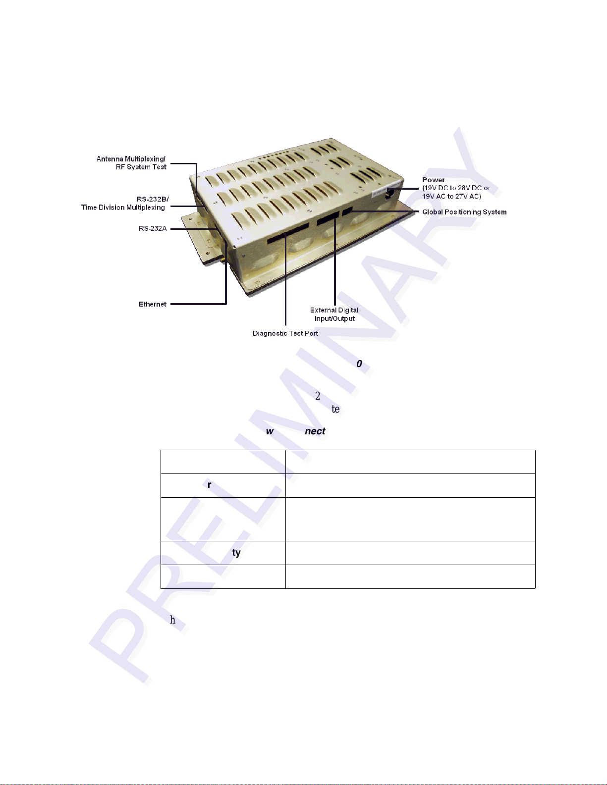
External Connectors
This section lists the MPI 6000 external connections. Figure 3-1 shows the MPI 6000
connector locations.
1.*eGo tags are fully compliant with ANSI INCITS 256:2001 and ISO 18000-6 standards. SeGo is a superset of the eGo
protocol.
3-3
Page 26
MPI 6000 Multi-Protocol Reader System Guide
Figure 3-1 Connector Locations on MPI 6000 Enclosure
Power
The MPI 6000 requires 19V DC to 28V DC or 19V AC to 27V AC RMS voltage
source.
Table 3-1 MPI 6000 Power Connection Specifications
Table 3-1 lists the MPI 6000 external power connector specifications.
Connector Type
Wire Gauge
Voltage
Polarity
Current
Two-Pin Terminal Block
12 – 30 AWG
19V to 28V DC or 19V to 27V AC RMS
Note If AC is used do not ground one end of the AC
input, the AC supply must float.
Either, power supply is polarity independent
2 amps
RF Antenna Connector
The MPI 6000 Reader typically is connected to an AA3152 Universal Toll Antenna
by a single low-loss RF cable. The antenna configuration is designed for overhead
mounting on a gantry or sign structure. Figure 3-2 shows the antenna connector on the
MPI 6000 enclosure.
3-4
Page 27
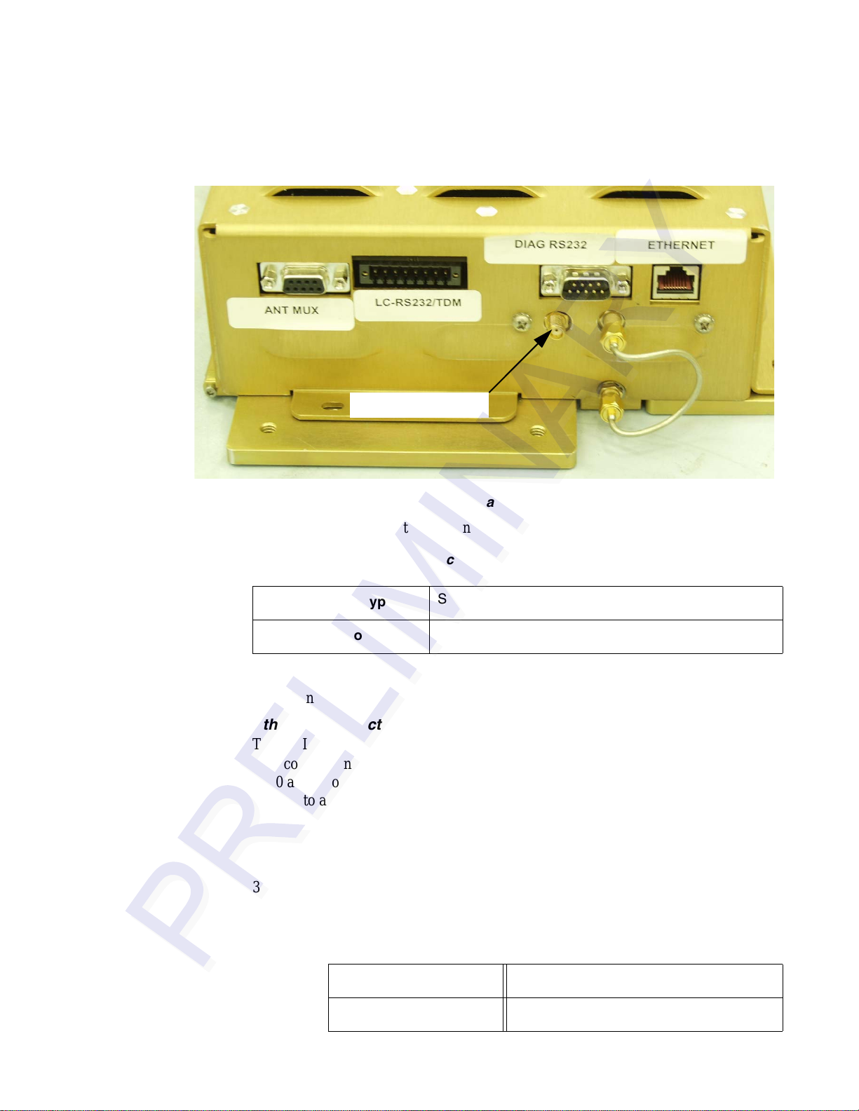
Antenna Connector
Installing and Configuring the MPI 6000
Figure 3-2 Antenna Connector Location
Table 3-2 lists the RF antenna connector parameters.
Table 3-2 RF Antenna Connector Specifications
Connector Type
Output Power
SMA Female
Up to 2 watts
RF Antenna Multiplexing/RF System Test Connector
This connector is used when a single MPI 6000 is used to operate multiple lanes.
Ethernet Connector
The MPI 6000 communicates with a host via an Ethernet communications protocol.
This connection requires an RJ
–45 connector. If you use a switch between the MPI
6000 and a host PC, you do not need a crossover cable. If you connect the MPI 6000
directly to a host PC then you need a crossover cable. If you set the host PC to
Dynamic, TransCore recommends that you set the IP address to Static.
RS–232A Serial Communications Connector
The MPI 6000 communicates via a serial, RS–232, communications protocol (Table
3-3). The diagnostic RS–232 port can be used to display the operating system boot
sequence.
Table 3-3 RS-232 Connector Specifications
Connector Type
Protocol
9 pin D-sub male
RS-232
3-5
Page 28
MPI 6000 Multi-Protocol Reader System Guide
Table 3-3 RS-232 Connector Specifications (continued)
Baud
Bits
Parity
Stop Bits
Flow Control
9600
8
None
1
None
Note: If you connect the MPI 6000 directly to a PC’s serial port, you must use a null-
modem.
By using the version command, you can display data about the configuration of the
MPI 6000 including its Internet Protocol (IP) address. (Mike, any more info here?)
RS-232B/TDM Connector
Information to be provided.
RS-232 Diagnostic Test Port Connector
Information to be provided.
External Digital Input/Output Connector
Information to be provided.
Global Positioning System Connector
Information to be provided.
Installing and Using the MPI 6000 Host Software
This section provides instructions for installing the MPI 6000 host software on your
host computer. You do not need the host to operate the MPI 6000, you can design an
application programming interface using the MPI 6000 commands. Those configura
tion commands are explained in “Configuration Commands and Responses” o n page
7-3 of this system guide.
If you choose to use TransCore’s host software program, follow the instructions in the
following sections.
Installing the Host Software
The MPI 6000 host program is used to communicate with the MPI 6000 and also display tag reads.
To install the MPI 6000 Host software
1. Load (what media is used? CD? FTP site?) the host software onto the host
computer.
-
3-6
Page 29

Installing and Configuring the MPI 6000
2. Run setup.exe and follow the commands to install the Host. The setup procedure
installs an icon named MPI 6000 Host on your computer desktop.
The following sections tell you how to use the MPI 6000 Host software.
Connecting to the MPI 6000 Reader with the Host Software
1. Double-click on the MPI 6000 Host icon.
2. Select UDP on the main screen.
3. In the UDP Command Link Config field, enter the IP address of the reader.
Write the IP address near the Ethernet connector on the MPI 6000 enclosure for
future reference.
4. Select Establish Command Link.
5. Select E.xit.
Configuring the MPI 6000 Reader Operating Frequency
1. Select the Configuration tab.
2. Select the Transceiver Configuration sub-tab.
3. Set the frequencies to desire values. Nominal values are 918.75 for downlink and
903 for uplink. Values must be between 902.25 and 903.75 or between 910 and
918.75 for the downlink. Values must be between 912.75 and 918.75 for the
uplink.
Operating the MPI 6000 Reader
1. Select Tags > FDOT.
2. Enter hex data into the IT2200 Write Data and SeGo Page Data fields. Use 32
hex characters for IT2200 (Allegro) and 16 hex characters for SeGo. This is the
data that is going to be written to the tag.
3. Select Read or Write in the SeGo Sequence Field. This sets the Read or Write
parameters for both IT2200 and SeGo tags.
4. Press Start to begin tag processing.
5. Tag responses should appear in the IT2200 and SeGo fields.
6. To stop the display or the response count, select the check boxes.
7. Press Stop to end tag processing.
8. Press Exit to close the FDOT page.
MPI 6000 Readers have been preconfigured for most needed operations. Parameters
such as attenuation, step-lock settings, and tag command sequences are set when the
reader powers up.
3-7
Page 30

MPI 6000 Multi-Protocol Reader System Guide
3-8
Page 31

4
Lane Tuning Guidelines
Page 32

Page 33

This chapter explains the importance of lane tuning for optimum
automatic vehicle identification (A VI) syste m performance and describes
the MPI 6000 functions and features that can assist you in tuning an AVI
lane.
Why You Need to Tune a Lane
Lane tuning is the procedure by which an installer can optimize the radio frequency
(RF) characteristics and the signal timing of an AV I-equipped toll lane for the perfor
mance dictated by the lane’s traffic requirements. Typically, consideration of these
factors is necessary for each individual lane, although in some installations it may be
possible to identify broader solutions, then apply these solutions to certain classes of
lanes having similar characteristics, followed by additional fine tuning on an individ
ual lane-by-lane basis. This process is necessitated by the radio link, which is subject
to varying factors such as lane type, the geometry of fixed objects near the capture
zone, interference from external sources, adjacent lane interference, natural nonhomogeneity of RF field strength within the ideal capture zone, and varying tag envi
ronments. These factors may vary widely within an installation and from lane to lane
within the same plaza. Furthermore, the type of technologies involved, either IT2200,
American Trucking Association (ATA), eGo, eGo Plus, Title 21 or Inter-Agency
Group (IAG), will play a significant role in tuning the lanes for operation. Knowing
the appropriate factors and available tools is necessary for the set-up and troubleshoot
ing of AVI lane s.
Chapter 4
Lane Tuning Guidelines
-
-
-
-
Required Equipment
You will need the following equipment and tools when you tune a lane:
TBD
Lane Tuning Parameters
Lane tuning parameters can be altered to effect required outcomes. This section lists
the properties that can be used to tune a lane.
Traffic Requirements
The traffic requirements of lane tuning include the following characteristics:
• The duration of the tag transaction, also known as handshake
4-3
Page 34

MPI 6000 Multi-Protocol Reader System Guide
• Maximum traffic speed in the lane, which is used to determine the required length
of the capture zone; also known as the footprint
• The type of lane, that is, express or mixed-use lane
• The presence of vehicle framing devices such as light curtains, which may dictate
the desired location of the first read point
• The presence of alternate toll collection devices, such as coin machines in mixed-
use lanes, which may dictate the desired first read point
• The width of the lane
Traf fic requirements are further defined by two terms, tag transaction or handshake
and capture zone or lane footprint.
Tag Transaction or Handshake
A handshake is defined as one complete transaction between a tag and the AVI equipment. The handshake is defined as a complete transaction because in many cases the
transaction consists of more than a simple read. The transaction may be a read com
mand followed by a general acknowledgment (GENACK), or a read command followed by a write command followed by a GENACK, or some other complex sequence
of commands. Each part of the handshake requires time, and the transaction with the
tag cannot be considered complete unless all the components have been completed. To
this end, there will be a minimum time associated with the handshake. It may be as lit
tle as a few milliseconds, or as high as 30 milliseconds or more.
-
-
Capture Zone or Lane Footprint
The footprint is the length of the capture zone measured on the pavement, starting at
the point of the first tag read and ending where tag reads stop, typically three or four
feet past the receive antenna (
ments of the capture zones of at least five diversely different vehicles equipped with
properly mounted tags. Ideally, RF margin plots taken at the time the footprint are
measured on a foot-by-foot basis, but for the basic measurements discussed in this
guide, all that is needed is the total footprint length from first read to last read.
Figure 4-1). This value is based on the actual measure-
4-4
Page 35

To Be Provided.
Lane Tuning Guidelines
Figure 4-1 Field Size, Shape, and Antenna Polarization Define the Reading
Range
One concern for lane tuning is how large the footprint needs to be for acceptable system reliability. A rule of thumb frequently applied to this problem is that there should
be time for a minimum of four complete transactions as the vehicle passes through the
capture zone. Thus, the system that has the more complex transaction requires the
larger footprint.
For example, if a toll agency requires an IT2200 tag read followed by a string of five
GENACKs, this constitutes a complete transaction, and the total time would be four
milliseconds for the IT2200 tag read plus four milliseconds for the five GENACKs for
a total of eight milliseconds for the entire handshake. Four complete handshakes
require 32 milliseconds. If the same agency has a maximum speed requirement of 60
mph through the lane, this translates to 88 feet per second, or 1 1.36 milliseconds/foot.
The agency could use the system with a footprint that is 32 milliseconds in duration,
which at 60 mph, translates to 11.36 milliseconds per foot or 2.82 feet. Any additional
footprint increases the reliability of the system because the system provides more
chances for the tag to interact with the reader.
1 read @ 4 milliseconds per read = 4 milliseconds
5 GENACK @ 0.8 milliseconds per GENACK= 4 milliseconds
= 8 milliseconds total, each full
handshake
For another example, if the toll agency requires three pages to be read from the tag,
followed by three pages of data to be written to the tag, followed by five GENACKS,
the total transaction time is
4-5
Page 36

MPI 6000 Multi-Protocol Reader System Guide
3 reads @ 4 milliseconds each = 12 milliseconds
3 writes @ 4 milliseconds each = 12 milliseconds
5 GENACKs @ 0.8 milliseconds each= 4 milliseconds
To complete 4 full handshakes (simply a rule of thumb), the vehicle would need to be
in the footprint for 112 milliseconds. If the agency requires 100 mph operation, the
vehicles travel one foot in 6.8 milliseconds. At this speed, the footprint would need to
be 16.47 feet long to satisfy this requirement.
This footprint value can change depending on the use of time division multiplexing
(TDM), which will increase the footprint requirements, or by using more sophisticated
polling methods, which may reduce the footprint requirements. Furthermore, the times
presented in this example for the individual components of the transaction can vary.
For example, a password-protected read or write operation can take longer to com
plete than an ordinary read or write and can impact the overall statistical reliability of
the transaction.
Note: Please consult with TransCore to assess the impact of the more sophisticated
types of transactions.
= 28 milliseconds total, each full hand-
shake
-
Given the uncertainties of any RF link due to reasons already discussed in this section,
a short transaction of only a few milliseconds has a statistically better chance of suc
ceeding than will a complex, longer 30-millisecond transaction. The tag is assumed to
remain in the footprint for a minimum period of time relative to the maximum vehicle
speed and the size of the footprint.
Once the length of the footprint has been determined, the presence of light curtains or
detection loops may dictate the point at which the first tag read should occur. Also,
manned lanes or mixed-use lanes typically require that the tag read occur at least a few
feet in front of the toll collection point. The speed requirements may be reduced for
these lanes and, hence, the footprint size. The point of the first read may be controlled
by antenna placement, uptilt angle, and RF power, which are discussed later in this
chapter. Likewise, if the lane is exceptionally wide or if there is a need for better cov
erage toward the lane sides, the antenna may be mounted higher or in line with other
antennas. A lower gain antenna may be used to increase the side coverage.
-
RF Factors
The RF factors involved in tuning an AVI system may include the following parameters:
• The downlink and uplink transmitted RF power
• Range control adjustments that can be made to the receiver
• Antenna type
-
4-6
• Antenna mounting, that is, lane position (relative to payment point, angle, and
height)
Page 37

Lane Tuning Guidelines
• The downlink and uplink source frequencies and interference from lanes sharing
same or close frequencies
• The antenna-tag orientation
RF power is the most important RF factor in lane tuning. Thirty dBm translates to onewatt nominal power. Increasing the RF power will, in general, increase the footprint.
There are other factors involved such as antenna angle and placement that may affect
the footprint, but increasing RF power will generally increase the signal and increase
both the footprint and the RF margins in the lane.
Because the RF power can create interference in adjacent or nearby lanes and degrade
the performance of the adjacent lane, the RF power should be adjusted so that mini
mum power is used to achieve the desired results.
Downlink and Uplink Transmitted RF Power
Downlink signal is the signal transmitted from the reader to the tag, and uplink signal
is the signal reflected back to the receiver from the tag. The impact of the downlink
and uplink power on footprint and lane performance is heav ily dependent on the pro
tocol type(s) in use in the lane. Table x-x (to be provided) is a general guide to the
influence of RF power on the footprint by protocol. Some of these factors are interre
lated to such aspects as antenna angle, antenna placement, and tag placement, so use
this information as a starting point and consider other aspects of lane tuning when
operating on any given lane.
-
-
-
Both downlink and uplink power are adjustable by tag protocol. In other words, in
multiple protocol systems, the RF power can be adjusted for each tag protocol in use,
independent of the other tag protocol.
Range Control Adjustments
Adjusting the range control allows the user to adjust the footprint separate from any
setting of the RF power. It is an adjustment on the sensitivity of the receiver and is
done independently for each tag protocol. The units are in decibels and vary from 0 to
20dB, with the higher number giving the smaller footprint. Range control always
exerts an effect on the footprint and performance separate from the tag protocol, but
the degree of the effect may be dependent on RF power and antenna parameters as
well. The most common use of range control is in multiple protocol situations, where
the first read point of tags with two differing protocols must be made to coincide
within a lane. In this situation, the power and antenna parameters are adjusted so that
the weaker protocol tags are reading at the appointed position, then range control is
used to adjust the first read point of the stronger protocol tags down to the same posi
tion as the other protocol. Range control can also be used in a sin gle protocol situation
to fine tune the first read position.
Frequency Considerations — Single Protocol
TBD
IT2200 or Title 21 Tag Protocol
TBD
-
This uplink frequency separation should repeat for additional lanes.
eGo Tag Protocol
TBD
4-7
Page 38

MPI 6000 Multi-Protocol Reader System Guide
ATA Tag Protocol
TBD
IAG Tag Protocol
TBD
Frequency Considerations — Multiple Protocols
TBD
Antenna-Tag Orientation
Antennas need to be oriented to match the tag orientation (Figure 4-2). Antennas also
need to match the tag placement and vice versa. For example, if the tag is placed in the
center of the windshield, the antennas should be placed overhead, centered, or nearly
centered in the lane. If the tag is placed to the side of the windshield, the antennas
should be placed overhead to the side matching the tag placement, or a side-mounted
antenna should be used. There are some exceptions to this, and in the overall system
planning, any variation from this rule should be discussed with TransCore at the earli
est possible time to minimize additional costs for altering the lane design, especially
after construction has started. Incorrect antenna placement may render the system’s
performance unacceptable and result in the eventual and expensive refitting of
antenna and communication hardware.
tions, and Figure 4-4 shows exterior tag mounting locations.
-
Figure 4-3 shows interior tag mounting loca-
4-8
Figure 4-2 Tag Orientation with Linearly Polarized Antenna
Page 39

Lane Tuning Guidelines
Figure 4-3 Upper Center Interior Windshield Tag Placement
Figure 4-4 Correct Exterior Tag Placement
Antenna Uptilt Angle
Adjusting the antenna uptilt angle directly affects the footprint and the point of first
tag read (
tag read farther from the antenna. However, at some uptilt angle, a point of diminishing return is reached where the RF power is too dispersed to activate the tag at the
start of the footprint. Increasing the antenna angle beyond this point will not move the
first read point farther out and may actually decrease the RF margin within the cap
ture zone. Also, increasing the angle may produce an area near the start of the capture
zone with spotty reads. The most commonly used range for antenna uptilt angles is
from 10 to 25 degrees with the lower angles producing the sharpest, most clearly
defined read zones. Setting the antenna uptilt angle below 10 degrees may cause
problems in reading tags mounted on windshie lds that are nearly vertical and in read
Figure 4-5). As expected, a greater uptilt angle will move the point of first
-
4-9
-
Page 40

MPI 6000 Multi-Protocol Reader System Guide
ing license plate tags.
Note: Tr ansCore does not recommend placing the antenna uptilt angles at less than five degrees.
Figure 4-5 Overhead Antenna Tilt Angle
Antenna Positioning Within the Lane
In lanes where the antennas are mounted side by side, TransCore recommends that you install the
transmit antenna toward the driver side of the traffic lane and the receiv e antenna toward the pas
senger side of the traffic lane. Antenna position in the lane also impacts lane performance.
Antenna mounting brackets should be designed so that you can adjust the antennas from front to
back and from side to side. In lanes that have no vehicle framing, such as some express lanes, the
front-to-back adjustment is not critical and can be minimized or eliminated. But, in these lanes it is
still valid to have at least ±2 feet (±0.61 m) of side adjustment. Side adjustment may be critical in
places where vehicles tend to travel to one side or another, such as in lanes that are wider than 12
feet (3.65 m). You can move the pair of antennas from side to side so that the centerline between
the antenna pair is located over the area of the lane where the majority of traffic travels. RF reflec
tors, such as toll booths and Jersey barriers, may require you to make side adjustments to achieve
adequate coverage to one side or the other.
The portion of the footprint with the highest RF margin has the highest probability of a successful
tag transaction. This portion of the footprint is the area directly under the antenna and extending
forward (upstream) a number of feet. If the length of the footprint is not an issue, such as the situa
tion in some lower speed mixed-use lanes, but the point of first read is critical, it may be advisable
to use a low antenna angle. Next, adjust the antenna position so that the first read occurs at the
desired point. Adjust the antenna position instead of fixing the antenna position and adjusting the
first read point by manipulating the antenna uptilt angle or the RF power. This adjustment may
-
-
-
4-10
Page 41

Lane Tuning Guidelines
enable you to operate the lane at a lower RF power, which is usually the preferred operational mode.
Signal Timing
TBD
4-11
Page 42

MPI 6000 Multi-Protocol Reader System Guide
4-12
Page 43

Lane Tuning Guidelines
4-13
Page 44

MPI 6000 Multi-Protocol Reader System Guide
4-14
Page 45

5
Optimizing MPI 6000 Reader System
Performance
Page 46

Page 47

Optimizing MPI 6000 Reader System
This chapter provides information to optimize the MPI 6000 performance
and reduce cross-lane interference.
Cross-Lane Interference in RFID Systems
Radio frequency identification (RFID) systems are subject to various types of interference that can affect the level of communications between a tag and a reader system. A
type of interference that can result from the operation of the reader system is called
cross-lane interference.
What Is Cross-Lane Interference?
Cross-lane interference occurs when the RF generated in one toll lane interrupts the
RFID operation in another lane that causes the affected lane to perform poorly . Before
diagnosing cross-lane interference, it is necessary to understand what constitutes a sat
isfactorily performing lane.
Chapter 5
Performance
-
Determining Acceptable Lane Performance
The criteria for optimal lane performance are usually set by the customer and can vary
according to the site requirements. In testing, acceptable lane operation criteria typi
cally are determined by the length of the RF footprint and the speed of the test vehicle.
Usually , a test vehicle’s speed is limited by the amount of the toll lane that can be used
for starting and stopping distances. Usually, testing speed is limited to 20 miles per
hour (mph) or 32 kilometers per hour (kph) or less.
An ideally performing toll lane will produce one handshake for every 4 milliseconds
of transaction time. At 20 mph (32 kph), the vehicle uses 34 milliseconds to travel
through 1.0 foot (0.3 m) of the footprint. If the footprint is 8 feet (2.4 m), this means
that the vehicle will spend approximately 272 milliseconds in the footprint. Based on a
vehicle speed of 20 mph (32 kph) and an 8-foot (2.4m) footprint, this yields an ideal
maximum number of 68 handshakes. Nulls and voids within the RF footprint will
lower this number, as will any other local sources of RF noise and stray reflections. A
rule of thumb for lane performance is to have 40 to 60 handshakes within an 8-foot
(2.4m) footprint with a test vehicle traveling at 20 mph (32 kph). A system that oper
ates with less than 40 handshakes should be tested for cross-lane interference.
-
-
5-3
Page 48

MPI 6000 Multi-Protocol Reader System Guide
Identifying Cross-Lane Interference
Cross-lane interference is identified by an area in the RF read zone, or footprint,
which has areas where a tag cannot be read. If a toll lane has been operating satisfacto
rily and then begins to show a degradation in system performance, that is, an increasing number of missed reads or a spotty read pattern, there is a probability that crosslane interference is occurring.
Cross-lane interference can be caused by the following:
• A downlink antenna transmitting strong RF beyond its lane boundaries
• Reflection of RF from fixed objects (e.g., toll plazas with low, metal roofs)
• Reflection of RF from moving objects (e.g., a passing tractor-trailer in an adjacent
lane)
A typical toll lane application encompasses more than a single lane. In some cases a
toll plaza can have more than eight lanes with each lane having separate RF transmit
ting (downlink) and receiving (uplink) antennas. As shown in Figure 5-1, the RF
transmitted within a lane is not bound by physical dividers such as lane barriers. With
multiple-lane applications, transmissions out of a lane can create areas of possible
cross-lane interference.
-
-
5-4
Figure 5-1 RF Footprint Extends Beyond Lane Boundaries
Page 49

Optimizing MPI 6000 Reader System Performance
Diagnosing Cross-Lane Interference
To diagnose this type of interference, first set the RF power in all lanes to a moderate
setting of 6 to 9 decibels (dB) for both downlink and uplink antennas. Next, tune a sin
gle lane. When tuning a lane be sure to use a tag and vehicle that have been used consistently at your site.
Once the lane has been tuned and you determine that it is working satisfactorily, perform lane tuning procedures in the adjacent lane. Continue for each lane in the toll
plaza.
If each adjacent lane tuning causes the previously tuned lane to start performing
poorly (i.e., spotty read zone or areas of no reads), cross-lane interference is indicated.
Remedying Cross-Lane Interference
Several methods exist to remedy cross-lane interference. These remedies are accomplished by software or hardware changes, or a combination of both. A remedy at one
site may not be appropriate at another site, so iterative methods of correcting this
interference are necessary.
-
Frequency Separation
Review the toll plaza frequency plan that was developed during the eGo 4110A
Reader System installation phase. There are two frequencies for each reader: down
link and uplink. For the eGo 4110A Reader System, all readers share the same downlink frequency, which is generally set to 918.75 MHz. Uplink frequencies should
alternate between 903.00 MHz and 910.00 MHz in adjacent lanes. For example, a
four-lane plaza would have the frequencies shown in
Table 5-1 Frequency Plan for Four-Lane Toll Plaza Using IT2200-series or Title
21 Tag Protocol
Lane Downlink Frequency Uplink Frequency
1 918.75 MHz 903.00 MHz
2 918.75 MHz 910.00 MHz
3 918.75 MHz 903.00 MHz
4 918.75 MHz 910.00 MHz
Table 5-1.
-
RF Power
A good rule of thumb when configuring a toll plaza is to set the RF attenuation at a
lower output and increase the RF power level as needed for optimal system operation.
This practice may provide you with RF attenuation settings at which your reader sys
tem can operate with minimal adjustment for cross-lane interference.
-
5-5
Page 50

MPI 6000 Multi-Protocol Reader System Guide
Time-Division Multiplexing
In situations where cross-lane interference can occur in an installation, and frequency
management is not sufficient to solve the problem, you may need to use time-division
multiplexing (TDM). By using the TDM function in readers, individual readers oper
ate only during interleaved time periods.
The TDM interconnect is provided via a differential RS–485 interface to a DB9 connector that is located on the reader card’s expansion board connector in slot 2. This
connection provides a synchronization interface between readers where RF interfer
ence between readers is reduced by multiplexing the RF reader transmission to independent time slots. Allowing each reader or group of readers to operate at an allotted
time eliminates interference from readers in adjacent lanes.
Although you need to configure the readers to operate using TDM, the interface connection for TDM can be provided to all the readers in a plaza before or during installation by connecting a pair of wires to the DB9 TDM connector of each reader as shown
Figure 5-2. No other equipment is necessary for the interconnection circuit. You
in
need to follow the polarity conventions as shown because this interface is polarity
dependent.
-
-
5-6
Figure 5-2 TDM Configuration Example
TransCore recommends Belden 89182 or 8132 cable. Using these low-loss, lowcapacitance twisted-pair cable, the maximum distance is 1000 feet (305 m). Cables
with lower capacitance can be used to run the TDM cables for longer distances while
maintaining signal integrity . This maximum distance may be slightly long er or shorter
depending on the cable used.
Page 51

Optimizing MPI 6000 Reader System Performance
Because the TDM signals are based on RS–485 signals, you can extend the length of
the TDM bus by using RS
–485 repeaters or by using fiber with converters. Either of
these two modifications should be used only when absolutely necessary in situations
where the TDM lengths need to exceed the 1000-foot (305-m) maximum distance.
Table 5-2 shows the pin designations and descriptions for the TDM connector.
Table 5-2 TDM Connector
Pin Name In/Out Description Recommended Connection
1 N/C N/A No connection N/C
2 N/C N/A No connection N/C
3 N/C N/A No connection N/C
4 N/C N/A No connection N/C
5 N/C N/A No connection N/C
6 N/C N/A No connection N/C
7 TDM (+) In/Out TDM synchronization positive Connect all red pin 7 wires
8 TDM (-) In/Out TDM synchronization negative Connect all black pin 8 wires
9 N/C N/A No connection N/C
together.
together.
To implement TDM, you must configure only one reader in the group as a master
reader for the TDM function. This reader will have a slightly shorter synchronization
period than the rest of the readers connected to it.
Note: The TDM synchronization period is set in 1.0-millisecond increments, whereas
the TDM delay and TDM duration are set in 0.5-millisecond increments.
Figure 5-3 illustrates a typical plaza configuration using TDM. There are three time
slots with three uplink frequencies. All the readers are configured with a downlink frequency of 916 MHz.
5-7
Page 52

MPI 6000 Multi-Protocol Reader System Guide
Figure 5-3 Typical Plaza Configuration Using TDM
The frequency settings and the 9-millisecond TDM time slots were determined based
on a Title 21 tag transaction. For other installations, the frequencies and TDM dura
tion need to be determined based on the type of transaction and expected vehicle
speeds for that installation.
of the time slots. Table 5-3 lists the settings for each reader in each time slot.
-
Figure 5-4 shows a timing diagram for the readers in each
5-8
Figure 5-4 TDM Timing Diagram
Page 53

Table 5-3 TDM Timing Settings
Optimizing MPI 6000 Reader System Performance
Time Slot TDM Delay TDM Duration
T1 0 ms (setting = 0) 9 ms (setting = 18) 31 ms (setting = 31)
T2 10 ms (setting = 20) 9 ms (setting = 18) 32 ms (setting = 32)
T3 20 ms (setting = 40) 9 ms (setting = 18) 33 ms (setting = 33)
a. Master reader TDM synchronization period equals 30 milliseconds.
TDM Synchronization
Period
a
Note: The TDM synchronization period is set in 1.0-millisecond increments, and the
TDM delay and TDM duration are set in 0.5-millisecond increments.
The TDM example shown in Figure 5-4 and Table 5-3 was designed with three time
slots; however, two time slots can be used instead depending on the number of
frequency channels and the timing. Implementing TDM with three time slots reduces
the time avaliable for a transaction in a given lane by a factor of three. Similarly,
implementing TDM with two time slots reduces the time avaliable for a transaction in
a given lane by a factor of two. Although it is possible to implement four or more time
slots, it is unlikely that more than three time slots are necessary or beneficial.
TransCore recommends that a guard-band of 1 millisecond be used between each of
the time slots to ensure that the readers in the previous time slot have sufficient time to
settle before the readers in the next time slot become active. This procedure can be
done by setting the TDM delay on each reader to account for a duration that is 1 milli
second longer than the actual duration and setting the TDM synchronization period to
a value that accounts for a duration 1 millisecond longer than the actual duration.
-
All the readers designated as slave readers in the plaza on the same TDM bus are
dependent on the synchronization signal from the mast er reader. In the event that the
synchronization pulse from the master reader stops functioning, or the TDM signal
from the master reader becomes disconnected from the rest of the readers in the plaza,
a provision in the readers allows a slave reader to serve as a backup master reader and
supply the synchronization pulse. Although this situation will cause the slave reader to
send an error message to the lane controller, the slave reader will continue to function
and provide the TDM synchronization pulse for the other operational readers on the
remaining TDM bus.
Because the location in the plaza where the signal break may occur is unknown,
TransCore recommends that provisions for a break anywhere in the line be consid
ered. Although the TDM synchronization period settings for the slave readers could
all be set at the same single value of 1 millisecond longer than the value used for the
TDM synchronization period on the master reader , they should be set at unique values
increasing at 1 millisecond for each reader, starting at a value 1 millisecond higher
than that of the master reader. This setting ensures that only one reader will provide
the synchronization pulse to a given group of readers in the plaza remaining on the
5-9
Page 54

MPI 6000 Multi-Protocol Reader System Guide
TDM bus in the event of either a TDM connection failure, or a failure of the TDM circuit in the master reader, which also reduces the number of readers that will generate
TDM failure messages in any one of these failure scenarios.
Physical Remedies
By adjusting the angle or position of the downlink and uplink antennas, you may be
able to minimize cross-lane interference.
Warning
Switch off RF power before working on antennas.
Adjusting the Antenna’s Uptilt Angle
Lowering an antenna’s uptilt angle between the antenna cover and the horizon generally reduces the interference (Figure 5-5).
5-10
Figure 5-5 Antenna Tilt Angle Adjustment
Page 55

Optimizing MPI 6000 Reader System Performance
Adjusting the Antenna Side Angle
In the eGo 4110A Reader System, you can adjust an antenna’s side angle so that the
RF transmits toward the center of the toll lane, placing the RF footprint into the lane.
If the side angle is too small, the footprint can project into the lane nearest to the tilted
antenna. If the side angle is too large and the RF footprint is projecting toward the
other antenna, you can reduce the side angle so that the antenna’s RF footprint is
evenly placed within the correct lane boundaries.
Figure 5-6 shows the downlink
antenna being tilted toward the center of the lane.
Figure 5-6 Downlink Antenna Side Angle Adjustment
Adjusting the Antenna Placement
Besides adjusting the antenna angles, you can also move the antenna farther back into
its overhead location so that the read zone does not extend as far in front of the trans
action area. By shortening the read zone, you may be able to reduce the required RF
output power, which will result in reduced probability of cross-lane interference.
You can also move the antenna pair from side to side within the lane. This adjustment
is used in lanes where the traffic travels closer to one side than another. For example,
in manned toll lanes, traffic tends to drive closer to the left side of the lane. The cen
-
terline between the antennas can be shifted to the left to compensate for this tendency.
Other Site Modifications
In rare instances, applying radar-absorbing foam to fixed areas of the toll plaza (e.g.,
metal roof) may reduce the incidence of interference.
5-11
-
Page 56

MPI 6000 Multi-Protocol Reader System Guide
5-12
Page 57

6
General Software Information
Page 58

Page 59

General Software Information
This chapter provides general software information about the design of
MPI 6000 system application software, as well as information required
for using reader system components in the design and integration of an
automated toll, traffic management, or automatic vehicle identification
(AVI) system.
General Software Information
All tag programmer commands are preceded by a start-of-message (<som>) ampersand character (&) followed by an end-of-message (<eom>) percent character (%). All
data after the <eom> character is ignored until the next <som> is detected.
Any & character that occurs in the message between the <som> and <eom> is converted to the backslash and at character (\@) sequence. Any % character is converted
to the \? character sequence. All \ characters are converted to the \\ sequence. All
<som> and <eom> character conversions are performed after the cyclic redundancy
check (CRC) has been performed on the transmit data and before the CRC is per
formed on the receive data.
Chapter 6
-
Reader commands contain only the message information and are not preceded by the
& and are not followed by the %.
Plan and Organize
Tags compatible with the eGo 4110A Reader System have sophisticated memory
organization. TransCore encourages the user to become familiar with the use and
organization of tag memory. Before starting a programming session, TransCore rec
ommends that you plan and organize the development steps.
Communications Protocols
The MPI 6000 communicates with a host by Ethernet or serial communications protocols.
Ethernet
The MPI 6000 can communicate via an Ethernet communications protocol. This connection requires an RJ–45 connector for the Ethernet receptacle. The Ethernet connector is an RJ-45 jack and uses a 10-base T interface. If you use a switch between the
MPI 6000 and the host personal computer (PC), no crossover cable is required. If the
MPI 6000 is connected directly to the host PC then a crossover cable is required. If the
-
6-3
Page 60

MPI 6000 Multi-Protocol Reader System Guide
host PC is set to Dynamic TransCore recommends that you set the IP address to Static.
Table 6-1 lists the connector pin assignments.
Table 6-1 Ethernet Connector
Pin Signal Description
1 TPTX+ Output Differential Transmit Data +
2 TPTX- Output Differential Transmit Data -
3 TPRX+ Input Differential Receive Data +
4 NOT CONNECTED N/A
5 NOT CONNECTED N/A
6 TPRX- Input Differential Receive Data -
7 NOT CONNECTED N/A
8 NOT CONNECTED N/A
Communications RS–232
The connector is an industry standard DB-9M plug. Table 6-2 lists this connector pin
assignments.
Table 6-2 Communications RS-232 Connector Parameters
Pin Signal Description
1 RSD Received line signal detect (not connected)
2 RXD Receive Data
3 TXD Transmit Data
4 DTR Data Terminal Ready (not connected)
5 GND Ground
6 DSR Data Set Ready (not connected)
7 RTS Request to Send
8 CTS Clear to Send
9 RI Ring indicator (not connected)
6-4
The RS-232B/Time-division multiplexing (TDM) connector is an 8-pin terminal
block header. The TDM signals must be isolated.
Table 6-3 lists this connector pin
assignments.
Page 61

General Software Information
Table 6-3 RS-232B/TDM Connector Parameters
Pin Signal Description
1 TXD Transmit Data
2 RXD Receive Data
3 DTR Data Terminal Ready (not connected)
4 RTS Request to Send
5 CTS Clear to Send
6 GND Ground
7 TDM + TDM positive signal
8 TDM - TDM negative signal
Diagnostic RS–232 Serial Communications
The MPI 6000 can communicate via a serial, RS–232, communications protocol
(
Table 6-4). The diagnostic RS–232 port can be used to display the operating system
boot sequence.
Table 6-4 RS-232 Connector Specifications
Connector Type
Protocol
Baud
Bits
Parity
Stop Bits
Flow Control
If you connect the MPI 6000 directly to a host PC serial port, you must use a nullmodem connector.
9 pin D-sub male
RS-232
9600
8
None
1
None
Diagnostic Commands (Mike?)
By using the version command, you can display data about the configuration of the
MPI 6000 including its Internet protocol (IP) address.
The RS-232 diagnostic connector can be used to check the external input/output status. Table 6-5 lists this connector pin assignments.
6-5
Page 62

MPI 6000 Multi-Protocol Reader System Guide
Table 6-5 Diagnostic RS-232 Connector Parameters
Pin Signal Description
1 5V PWR 5V power supply for I/O board
2 GND GND
3 I/O Signal 1 Input/output signal 1
4 I/O Signal 2 Input/output signal 2
5 I/O Signal 3 Input/output signal 3
6 I/O Signal 4 Input/output signal 4
7 Tag in Field 1 Contact Closure 1 for Tag in Field Signal
8 Tag in Field 2 Contact Closure 2 for Tag in Field Signal
Reader Command Protocol
The MPI 6000 implements command requests, data acknowledgements, command
responses, asynchronous responses, software flow control, and unsolicited status mes
sages as required for AVI system configuration and operation. The messages are
defined in this section.
Command request messages are initiated and used by the host to request specific
actions to be performed by the MPI 6000.
Data acknowledge messages are initiated and used by the MPI 6000 to signal the
reception of command request messages received from the host. Additionally, data
acknowledge messages are initiated and used by the host to signal the reception of
command response, asynchronous response, software flow control and unsolicited sta
tus messages received from the MPI 6000.
Command response messages are initiated by the MPI 6000 in response to specific
command request messages received from the host.
Asynchronous response messages are optionally initiated by the MPI 6000 in
response to specific command request messages received from the host.
Software flow control messages are initiated and used by the MPI 60000 System to
inform the host to start or stop sending command request messages. Additionally , soft
ware flow control messages are initiated and used by the host to inform the MPI
60000 System to start or stop sending messages.
-
-
-
6-6
Unsolicited status messages are initiated and used by the MPI 60000 System to
inform the host about specific warning or error conditions in the MPI 60000 System.
The host sends command request messages to the MPI 6000. The MPI 6000 after
receiving command request messages from the host sends data acknowledge mes
-
sages, command response messages, asynchronous response messages and if required
Page 63

General Software Information
software flow control messages to the host. The host on receiving command response
messages, asynchronous response messages and software flow control messages from
the MPI 6000 sends data acknowledge messages to the MPI 6000.
Additionally , the MPI 6000 sends unsoli cited status messages to the host. The host on
receiving unsolicited status messages from the MPI 6000 sends data acknowledge
messages to the MPI 6000.
The MPI 6000 implements message sequence numbers and command sequence numbers in all of the message types (e.g. command request, data acknowledge, command
response, asynchronous response, software flow control and unsolicited status). The
host and the MPI 6000 must implement independent transmit and receive counters for
both the message sequence numbers and the command sequence numbers. The trans
mit counters are used in the generation of the transmitted messages and the receive
counters are used in the received message out-of-sequence error checking. An out-ofsequence error indicates that a message has been missed.
The host’s message sequence numbers independently track the number of messages
sent to the MPI 6000. The MPI 6000’s message sequence numbers independently
track the number of messages sent to the host. These message sequence numbers are
used on the receiving end to determine if a message has been missed. See the software
communication sequence number controls section for more details.
-
The host’s command sequence numbers for each command group independently track
the number of command request messages sent to the MPI 6000. The MPI 6000’s
command sequence numbers for each command group independently track the num
ber of software flow control and unsolicited status messages sent to the host. These
command sequence numbers are used on the receiving end to determine if the appro
priate message as specified above has been missed. See the software communication
sequence number controls section for more details.
-
UDP/IP Fast Ethernet Communications Protocol
The UDP/IP fast Ethernet communications protocol implements the UDP/IP fast
Ethernet protocol as specified in the RealFast UDP/IP Core Design Specification
(RealFast Document Number
Command Request Message
The host sends command request messages to the MPI 6000 as required for system
operation. The host and the MPI 6000 uses the following UDP/IP fast Ethernet com
munications command request message shown here:
<len> <msgSeqNum> <cmd> <cmdSeqNum> [<data>] <checksum>
where
<len> = length, a word that specifies the number of bytes in the entire message.
RFHC04026-V042).
-
-
<msgSeqNum> = message sequence number, a byte that specifies the message
sequence number of the message. See the software communication sequence number
controls section for details.
6-7
Page 64

MPI 6000 Multi-Protocol Reader System Guide
<cmd> = command, a word that specifies the system command. See the command
sections for details.
<cmdSeqNum> = command sequence number, a byte that specifies the command
sequence number of the message. See the software communication sequence number
controls section for details.
[<data>] = optional data payload that varies in length from 0 to 65 bytes and is asso-
ciated with each specific command. See the command sections for details.
<checksum> = checksum, a byte that specifies the checksum of the message.
Data Acknowledge Message
The MPI 6000 sends data acknowledge messages to the host after receiving command
request messages from the host.
The host sends data acknowledge messages to the MPI 6000 after receiving command
response messages, asynchronous response messages, software flow control messages
and unsolicited status messages from the MPI 6000. The host and the MPI 6000 uses
the following UDP/IP fast Ethernet communications data acknowledge message as
shown here:
<len> <msgSeqNum> <cmd> <cmdSeqNum> <resp> <msgSeqNumAck> <checksum>
where
<len> - length, word that specifies the number of bytes in the entire message.
<msgSeqNum> - message sequence number, byte that specifies the message sequence
number of the message. See the software communication sequence number controls
section for details.
<cmd> - command, word that specifies the system command. See the command sec-
tions for details.
<cmdSeqNum> - command sequence number, byte that specifies the command
sequence number of the message. See the software communication sequence number
controls section for details.
<resp> - response, word that specifies the system response. See the response sections
for details.
<msgSeqNumAck> - message sequence number acknowledge, byte that specifies the
message sequence number of the message being acknowledged. See the software
communication sequence number controls section for details.
<checksum> - checksum, byte that specifies the checksum of the message.
Command Response Message
The MPI 6000 after receiving command request messages from the host sends command response messages to the host.
6-8
The host and the MPI 6000 uses the following UDP/IP fast Ethernet communications
command response message shown here:
Page 65

General Software Information
<len> <msgSeqNum> <cmd> <cmdSeqNum> <resp> [<data>] <checksum>
where
<len> = length, a word that specifies the number of bytes in the entire message.
<msgSeqNum> = message sequence number, a byte that specifies the message
sequence number of the message. See the software communication sequence number
controls section for details.
<cmd> = command, word that specifies the system command. See the command sec-
tions for details.
<cmdSeqNum> = command sequence number, a byte that specifies the command
sequence number of the message. See the software communication sequence number
controls section for details.
<resp> = response, a word that specifies the system response. See the response sec-
tions for details.
[<data>] = optional data payload that varies in length from 0 to 63 bytes and is asso-
ciated with each specific response. See the response sections for details.
<checksum> = checksum, a byte that specifies the checksum of the message.
Asynchronous Response Message
The MPI 6000 after receiving command request messages from the host optionally
sends asynchronous response messages to the host.
The host and the MPI 6000 uses the following UDP/IP fast Ethernet communications
asynchronous response message shown here:
<len> <msgSeqNum> <cmd> <cmdSeqNum> <resp> [<data>] <checksum>
where
<len> = length, a word that specifies the number of bytes in the entire message.
<msgSeqNum> = message sequence number, a byte that specifies the message
sequence number of the message. See the software communication sequence number
controls section for details.
<cmd> = command, word that specifies the system command. See the command sec-
tions for details.
<cmdSeqNum> = command sequence number, a byte that specifies the command
sequence number of the message. See the software communication sequence number
controls section for details.
<resp> = response, a word that specifies the system response. See the response sections for details.
[<data>] - optional data payload that varies in length from 0 to 63 bytes and is associated with each specific response. See the response sections for details.
<checksum> = checksum, a byte that specifies the checksum of the message.
6-9
Page 66

MPI 6000 Multi-Protocol Reader System Guide
Software Flow Control Message
The MPI 6000 after receiving command request messages from the host optionally
sends software flow control messages to the host as required for system operation.
The host optionally sends software flow control messages to the MPI 6000 as required
for host operation.
The host and the MPI 6000 uses the following UDP/IP fast Ethernet communications
software flow control message shown here:
<len> <msgSeqNum> <cmd> <cmdSeqNum> <resp> <checksum>
where
<len> = length, a word that specifies the number of bytes in the entire message.
<msgSeqNum> = message sequence number, a byte that specifies the message
sequence number of the message. See the software communication sequence number
controls section for details.
<cmd> = command, a word that specifies the system command. See the command
sections for details.
<cmdSeqNum> - command sequence number, a byte that specifies the command
sequence number of the message. See the software communication sequence number
controls section for details.
<resp> = response, a word that specifies the system response. See the response sec-
tions for details.
<checksum> = checksum, a byte that specifies the checksum of the message.
Unsolicited Status Message
The MPI 6000 sends unsolicited status messages to the host as required for system
operation.
The host and the MPI 6000 uses the following UDP/IP fast Ethernet communications
unsolicited status message shown here:
<len> <msgSeqNum> <cmd> <cmdSeqNum> <status> [<data>] <checksum>
where
<len> = length, a word that specifies the number of bytes in the entire message.
<msgSeqNum> = message sequence number, a byte that specifies the message
sequence number of the message. See the software communication sequence number
controls section for details.
<cmd> = command, a word that specifies the system command. See the command
sections for details.
6-10
<cmdSeqNum> = command sequence number, a byte that specifies the command
sequence number of the message. See the software communication sequence number
controls section for details.
Page 67

General Software Information
<status> = status, a word that specifies the system status. See the response sections
for details.
[<data>] = optional data payload that varies in length from 0 to 63 bytes and is asso-
ciated with each specific response. See the response sections for details.
<checksum> = checksum, a byte that specifies the checksum of the message.
Serial Communications Protocol
The serial communications protocol implements the TransCore error correction protocol (ECP) serial standard.
Command Request Message
The host sends command request messages to the MPI 6000 as required for system
operation.
The host and the MPI 6000 uses the following serial communications command
request message as shown here:
<som> <len> <msgSeqNum> <cmd> <cmdSeqNum> [<data>] <crc16> <eom>
where
<som> - start of message, byte that specifies the start of the message which is defined
as the ASCII character &.
<len> - length, word that specifies the number of bytes in the entire message.
<msgSeqNum> - message sequence number, byte that specifies the message sequence
number of the message. See the software communication sequence number controls
section for details.
<cmd> - command, word that specifies the system command. See the command sections for details.
<cmdSeqNum> - command sequence number, byte that specifies the command
sequence number of the message. See the software communication sequence number
controls section for details.
[<data>] - optional data payload that varies in length from 0 to 65 bytes and is associ-
ated with each specific command. See the command sections for details.
<crc16> - 16 bit cyclic redundancy check, word that specifies the 16 bit cyclic redundancy check of the message exclusive of the <som> and <eom> bytes. The polyno-
mial for the CRC calculation is X16+X12+X5+1 with a divisor polynome of 1021H
and an initial value of FFFFH for a CCITT16 type CRC.
<eom> - end of message, byte that specifies the end of the message which is defined
as the ASCII character %.
6-11
Page 68

MPI 6000 Multi-Protocol Reader System Guide
Data Acknowledge Message
The MPI 6000 after receiving command request messages from the host sends data
acknowledge messages to the host.
The host after receiving command response messages, asynchronous response messages, software flow control messages and unsolicited status messages from the MPI
6000 sends data acknowledge messages to the MPI 6000.
The host and the MPI 6000 uses the following serial communications data acknowledge message as shown here:
<som> <len> <msgSeqNum> <cmd> <cmdSeqNum> <resp> <msgSeqNumAck> <crc16> <eom>
where
<som> - start of message, byte that specifies the start of the message which is defined
as the ASCII character &.
<len> - length, word that specifies the number of bytes in the entire message.
<msgSeqNum> - message sequence number, byte that specifies the message sequence
number of the message. See the software communication sequence number controls
section for details.
<cmd> - command, word that specifies the system command. See the command sec-
tions for details.
<cmdSeqNum> - command sequence number, byte that specifies the command
sequence number of the message. See the software communication sequence number
controls section for details.
<resp> - response, word that specifies the system response. See the response sections
for details.
<msgSeqNumAck> - message sequence number acknowledge, byte that specifies the
message sequence number of the message being acknowledged. See the software
communication sequence number controls section for details.
<crc16> - 16 bit cyclic redundancy check, word that specifies the 16 bit cyclic redun-
dancy check of the message exclusive of the <som> and <eom> bytes. The polyno-
mial for the CRC calculation is X16+X12+X5+1 with a divisor polynome of 1021H
and an initial value of FFFFH for a CCITT16 type CRC.
<eom> - end of message, byte that specifies the end of the message which is defined
as the ASCII character %.
Command Response Message
The MPI 6000 after receiving command request messages from the host sends command response messages to the host.
The host and the MPI 6000 uses the following serial communications command
response message as shown here:
<som> <len> <msgSeqNum> <cmd> <cmdSeqNum> <resp> [<data>] <crc16> <eom>
6-12
Page 69

General Software Information
where
<som> - start of message, byte that specifies the start of the message which is defined
as the ASCII character &.
<len> - length, word that specifies the number of bytes in the entire message.
<msgSeqNum> - message sequence number, byte that specifies the message sequence
number of the message. See the software communication sequence number controls
section for details.
<cmd> - command, word that specifies the system command. See the command sec-
tions for details.
<cmdSeqNum> - command sequence number, byte that specifies the command
sequence number of the message. See the software communication sequence number
controls section for details.
<resp> - response, word that specifies the system response. See the response sections
for details.
[<data>] - optional data payload that varies in length from 0 to 63 bytes and is associ-
ated with each specific response. See the response sections for details.
<crc16> - 16 bit cyclic redundancy check, word that specifies the 16 bit cyclic redun-
dancy check of the message exclusive of the <som> and <eom> bytes. The polyno-
mial for the CRC calculation is X16+X12+X5+1 with a divisor polynome of 1021H
and an initial value of FFFFH for a CCITT16 type CRC.
<eom> - end of message, byte that specifies the end of the message which is defined
as the ASCII character %.
Asynchronous Response Message
The MPI 6000 after receiving command request messages from the host optionally
sends asynchronous response messages to the host.
The host and the MPI 6000 uses the following serial communications asynchronous
response message as shown here:
<som> <len> <msgSeqNum> <cmd> <cmdSeqNum> <resp> [<data>] <crc16> <eom>
where
<som> - start of message, byte that specifies the start of the message which is defined
as the ASCII character &.
<len> - length, word that specifies the number of bytes in the entire message.
<msgSeqNum> - message sequence number, byte that specifies the message sequence
number of the message. See the software communication sequence number controls
section for details.
<cmd> - command, word that specifies the system command. See the command sections for details.
6-13
Page 70

MPI 6000 Multi-Protocol Reader System Guide
<cmdSeqNum> - command sequence number, byte that specifies the command
sequence number of the message. See the software communication sequence number
controls section for details.
<resp> - response, word that specifies the system response. See the response sections
for details.
[<data>] - optional data payload that varies in length from 0 to 63 bytes and is associ-
ated with each specific response. See the response sections for details.
<crc16> - 16 bit cyclic redundancy check, word that specifies the 16 bit cyclic redun-
dancy check of the message exclusive of the <som> and <eom> bytes. The polyno-
mial for the CRC calculation is X16+X12+X5+1 with a divisor polynomial of 1021H
and an initial value of FFFFH for a CCITT16 type CRC.
<eom> - end of message, byte that specifies the end of the message which is defined
as the ASCII character %.
Software Flow Control Message
The MPI 6000 after receiving command request messages from the host optionally
sends software flow control messages to the host as required for system operation.
The host optionally sends software flow control messages to the MPI 6000 as required
for host operation.
The host and the MPI 6000 uses the following serial communications software flow
control message as shown here:
<som> <len> <msgSeqNum> <cmd> <cmdSeqNum> <resp> <crc16> <eom>
where
<som> - start of message, byte that specifies the start of the message which is defined
as the ASCII character &.
<len> - length, word that specifies the number of bytes in the entire message.
<msgSeqNum> - message sequence number, byte that specifies the message sequence
number of the message. See the software communication sequence number controls
section for details.
<cmd> - command, word that specifies the system command. See the command sec-
tions for details.
<cmdSeqNum> - command sequence number, byte that specifies the command
sequence number of the message. See the software communication sequence number
controls section for details.
<resp> - response, word that specifies the system response. See the response sections
for details.
6-14
<crc16> - 16 bit cyclic redundancy check, word that specifies the 16 bit cyclic redundancy check of the message exclusive of the <som> and <eom> bytes. The polyno-
mial for the CRC calculation is X16+X12+X5+1 with a divisor polynome of 1021H
and an initial value of FFFFH for a CCITT16 type CRC.
Page 71

General Software Information
<eom> - end of message, byte that specifies the end of the message which is defined
as the ASCII character %.
Unsolicited Status Message
The MPI 6000 sends unsolicited status messages to the host as required for system
operation.
The host and the MPI 6000 uses the following serial communications unsolicited status message as shown here:
<som> <len> <msgSeqNum> <cmd> <cmdSeqNum> <status> [<data>] <crc16> <eom>
where
<som> - start of message, byte that specifies the start of the message which is defined
as the ASCII character &.
<len> - length, word that specifies the number of bytes in the entire message.
<msgSeqNum> - message sequence number, byte that specifies the message sequence
number of the message. See the software communication sequence number controls
section for details.
<cmd> - command, word that specifies the system command. See the command sec-
tions for details.
<cmdSeqNum> - command sequence number, byte that specifies the command
sequence number of the message. See the software communication sequence number
controls section for details.
<status> - status, word that specifies the system status. See the response sections for
details.
[<data>] - optional data payload that varies in length from 0 to 63 bytes and is asso-
ciated with each specific response. See the response sections for details.
<crc16> - 16 bit cyclic redundancy check, word that specifies the 16 bit cyclic redun-
dancy check of the message exclusive of the <som> and <eom> bytes. The polyno-
mial for the CRC calculation is X16+X12+X5+1 with a divisor polynomial of 1021H
and an initial value of FFFFH for a CCITT16 type CRC.
<eom> - end of message, byte that specifies the end of the message which is defined
as the ASCII character %.
6-15
Page 72

MPI 6000 Multi-Protocol Reader System Guide
6-16
Page 73

7
Configuration Commands and
Responses
Page 74

Page 75

Configuration Commands and Responses
This chapter describes the MPI 6000 interface commands that are used
to configure the reader.
Configuring the MPI 6000
MPI 6000 Readers have been preconfigured for most needed operations. Parameters
such as attenuation, step-lock settings, and tag command sequences are set when the
reader powers up. The Set Frequency command is the only required configuration
command. You must issue this command before the MPI 6000 Reader can read tags.
Required Commands to Set Up MPI 6000 Reader
This section describes the configuration commands that are used to set up the MPI
6000.
Set Frequency
This section describes the Set Frequency command that is used to set the MPI 6000
frequency.
Frequency command data.
Figure 7-1 shows the command transaction process. Table 7-1 lists the Set
Chapter 7
Figure 7-1 Set Frequency Command Process
This command sets the A Counter and B Counter least significant bits (LSB) for the
specified source.
Table 7-1 Set Frequency Command Parameters
Set Frequency Command Data
Bit 7 Bit 6 Bit 5 Bit 4 Bit 3 Bit 2 Bit 1 Bit 0
Set Frequency Command 08H
Unused Source 0XH
Data
Payload
7-3
Page 76

MPI 6000 Multi-Protocol Reader System Guide
Table 7-1 Set Frequency Command Parameters
Unused A Counter XXH
Unused B Counter LSBs 0XH
Carriage Return 0DH
Table 7-2 shows the Set Frequency Response parameters.
Table 7-2 Set Frequency Response Parameters
Set Frequency Response Data
Bit 7 Bit 6 Bit 5 Bit 4 Bit 3 Bit 2 Bit 1 Bit 0
Set Frequency Command 08H
Unused Source 0XH
Acknowledge 00H
Carriage Return 0DH
Data
Payload
The Source field identifies the source for the associated N Counter information (Table
7-3).
Table 7-3 Descriptions of Sources
Source Definition
0 Source 1
1 Source 2
7-4
A Counter – This field contains the data for the binary five-bit A Counter of the PLL.
The A and B counters combine to form the 18-bit N Counter. The valid range of the A
Counter data field is 00H to 1FH.
B Counter LSBs – This field contains the LSB for the binary 13-bit B Counter of the
PLL. The A and B counters combine to form the 18-bit N Counter. The valid range of
the data field is 0H to 3H. The B Counter value is 007XH, where X = B Counter
LSBs.
The PLL frequency spreadsheet contains the values used to set the A Counter and the
B Counter. This command will be modified to allow the system to send frequency val
ues instead of A and B counters.
-
Page 77

Configuration Commands and Responses
System Interface Command Group Commands
This section describes the system commands used to configure the MPI 6000.
Table 7-4 System Interface Command Group
System Interface Command Command Code
System Identify 0000H
Set Communications Baud Rate 0001H
Get Communications Baud Rate 0002H
Set Time and Date 0003H
Get Time and Date 0004H
Firmware Download 0005H
Reset Reader 0006H
Get Stored Tag Response Message 0007H
Get Number of Stored Tag Response Messages 0008H
Delete All Stored Tag Response Messages 0009H
Get System Startup Status 000AH
Get Lane Controller Interface Status 000BH
Get System Interface Status 000CH
Get DigBrd Hdwr Remote Inventory 000DH
Get DigBrd CPU Boot Fmwr Remote Inventory 000EH
Get DigBrd CPU Appl Fmwr Remote Inventory 000FH
Get DigBrd FPGA UDP/IP Core Fmwr Remote Inventory 0010H
Set UDP/IP Core Lane Controller IP Address and Port Number Parameters 0011H
Get UDP/IP Core Lane Controller IP Address and Port Number Parameters 0012H
Set UDP/IP Core IP Address 0013H
Get UDP/IP Core IP Address 0014H
Get UDP/IP Core UDP Port Number 0015H
Each of the system command group commands is listed in this section.
7-5
Page 78

MPI 6000 Multi-Protocol Reader System Guide
System Identify
System Identify Command Data
System Identify Command 0000H
System Identify Response Data
System Identify Command 0000H
Vendor Name
Versi o n ID
Part Number
Serial Number
Payload
Payload
System Identify Data Sizes
Data
Data
7-6
System Identify Data
Vendor Name 15 Bytes
Versi o n ID 15 Bytes
Part Number 15 Bytes
Serial Number 15 Bytes
Data
Size
Set Communications Baud Rate
Set Communications Baud Rate Command Data
Set Communications Baud Rate Command 0001H
Baud Rate Data Code XXH
Data
Payload
Page 79

Configuration Commands and Responses
Set Communications Baud Rate Response Data
Set Communications Baud Rate Command 0001H
Payload
Baud Rate Data Codes
Baud Rate
19,200 bps 0CH
38,400 bps (System Default) 0DH
57,600 bps 0EH
115,200 bps 0FH
Code
Get Communications Baud Rate
Data
Data
Get Communications Baud Rate Command Data
Get Communications Baud Rate Command 0002H
Get Communications Baud Rate Response Data
Get Communications Baud Rate Command 0002H
Baud Rate Data Code XXH
Data
Payload
Data
Payload
7-7
Page 80

MPI 6000 Multi-Protocol Reader System Guide
Set Time and Date
Set Time and Data Command Data
Set Time and Date Command 0003H
Hours XXH
Minutes XXH
Seconds XXH
Hundredths of Seconds XXH
Month XXH
Day XXH
Ye a r XXH
Set Time and Data Response Data
Set Time and Date Command 0003H
Data
Payload
Data
Payload
7-8
Time and Date Data Ranges
Time and Date Data Data Range
Hours 0 to 23 (00H to 17H)
Minutes 0 to 59 (00H to 3BH)
Seconds 0 to 59 (00H to 3BH)
Hundredths of Seconds 0 to 99 (00H to 63H)
Month 1 to 12 (01H to 0CH)
Day 1 to 31 (01H to 1FH)
Ye a r 0 to 99 (00H to 63H)
Page 81

Get Time and Date
Configuration Commands and Responses
Get Time and Data Command Data
Get Time and Date Command 0004H
Get Time and Data Response Data Data Payload
Set Time and Date Command 0004H
Hours XXH
Minutes XXH
Seconds XXH
Hundredths of Seconds XXH
Month XXH
Day XXH
Ye a r XXH
Data
Payload
Firmware Download
Firmware Download Command Data
Firmware Download Command 0005H
Firmware Download Response Data
Firmware Download Command 0005H
Payload
Payload
Data
Data
7-9
Page 82

MPI 6000 Multi-Protocol Reader System Guide
The Firmware Download command is implemented as defined for
both UDP/IP Fast Ethernet and serial communications.
Reset Reader
Reset Reader Command Data
Reset Reader Command 0006H
Reset Reader Control Word A5A5H
Reset Reader Response Data
Reset Reader Command 0006H
Data
Payload
Data
Payload
Get Stored Tag Response Message
Get Stored Tag Response Message Command Data
Data
Payload
7-10
Get Stored Tag Response Message Command 0007H
Stored Tag Response Message Number XXXXH
Get Stored Tag Response Message Response Data
Get Stored Tag Response Message Command 0007H
Stored Tag Response Message Number XXXXH
Stored Tag Response Message Data
Data
Payload
Page 83

Configuration Commands and Responses
Get Number of Stored Tag Response Messages
Get Number of Stored Tag Response Messages Command Data
Get Number of Stored Tag Response Messages Command 0008H
Get Number of Stored Tag Response Messages Response Data
Get Number of Stored Tag Response Messages Command 0008H
Number of Stored Tag Response Messages XXXXH
Data
Payload
Data
Payload
Delete All Stored Tag Response Messages
Delete All Stored Tag Response Messages Command Data
Data
Payload
Delete All Stored Tag Response Messages Command 0009H
Delete All Stored Tag Response Messages Control Word A5A5H
Delete All Stored Tag Response Messages Response Data
Delete All Stored Tag Response Messages Command 0009H
Data
Payload
Get System Startup Status
7-11
Page 84

MPI 6000 Multi-Protocol Reader System Guide
Get System Startup Status Command Data
Get System Startup Status Command 000AH
Get System Startup Status Response Data
Get System Startup Status Command 000AH
System Startup Module Number (System Initialization) XXXXH
System Timer Initialization Status Error Number XXXXH
System BMU Initialization Status Error Number XXXXH
System Queue Create Status Error Number XXXXH
System Task Create Status Error Number XXXXH
Data
Payload
Data
Payload
Get Lane Controller Interface Status
7-12
Get Lane Controller Interface Status Command Data
Get Lane Controller Interface Status Command 000BH
Get Lane Controller Interface Status Response Data
Get Lane Controller Interface Status Command 000BH
Module Number XXXXH
Error Number XXXXH
Data
Payload
Data
Payload
Page 85

Get System Interface Status
Configuration Commands and Responses
Get System Interface Status Command Data
Get System Interface Status Command 000CH
Get System Interface Status Response Data
Get System Interface Status Command 000CH
Module Number XXXXH
Error Number XXXXH
Data
Payload
Data
Payload
Get DigBrd Hdwr Remote Inventory
Get Digital Board Hardware Remote Inventory Command Data
Data
Payload
Get Digital Board Hardware Remote Inventory Command 000DH
Get Digital Board Hardware Remote Inventory Response Data
Get Digital Board Hardware Remote Inventory Command 000DH
Vendor Name
Versi o n ID
Part Number
Serial Number
Data
Payload
7-13
Page 86

MPI 6000 Multi-Protocol Reader System Guide
Hardware Remote Inventory Data Sizes
Hardware Remote Inventory Data
Vendor Name 15 Bytes
Versi o n ID 15 Bytes
Part Number 15 Bytes
Serial Number 15 Bytes
Data
Size
Get DigBrd CPU Boot Fmwr Remote Inventory
Get Digital Board CPU Boot Firmware Remote Inventory
Command Data
Get Digital Board CPU Boot Firmware Remote Inventory Command 000EH
Data
Payload
7-14
Get Digital Board CPU Boot Firmware Remote Inventory
Response Data
Get Digital Board CPU Boot Firmware Remote Inventory Command 000EH
Vendor Name
Versi o n ID
Part Number
Data
Payload
Get DigBrd CPU Appl Fmwr Remote Inventory
Get Digital Board CPU Application Firmware Remote Inventory
Command Data
Get Digital Board CPU Application Firmware Remote Inventory
Command
Data
Payload
000FH
Page 87

Configuration Commands and Responses
Get Digital Board CPU Application Firmware Remote Inventory
Get Digital Board CPU Application Firmware Remote Inventory
Command
Vendor Name
Versi o n ID
Part Number
Response Data
000FH
Get DigBrd FPGA UDP/IP Core Fmwr Remote Inventory
Get Digital Board FPGA UDP/IP Core Firmware Remote Inventory
Command Data
Get Digital Board FPGA UPD/IP Core Firmware Remote Inventory
Command
0010H
Data
Payload
Data
Payload
Get Digital Board FPGA UDP/IP Core Firmware Remote Inventory
Response Data
Get Digital Board FPGA UPD/IP Core Firmware Remote Inventory
Command
Vendor Name
Versi o n ID
Part Number
Firmware Remote Inventory Data Sizes
Data
Payload
0010H
7-15
Page 88

MPI 6000 Multi-Protocol Reader System Guide
Firmware Remote Inventory Data
Vendor Name 15 Bytes
Versi o n ID 15 Bytes
Part Number 15 Bytes
Data
Size
Set UDP/IP Core Lane Controller Parameters
Set UDP/IP Core Lane Controller Parameters Command Data
Set UDP/IP Core Lane Controller Parameters Command 0011H
IP Address (MSW) XXXXH
IP Address (LSW) XXXXH
Por t Number XXXXH
Data
Payload
7-16
Set UDP/IP Core Lane Controller Parameters Response Data
Set UDP/IP Core Lane Controller Parameters Command 0011H
Payload
Get UDP/IP Core Lane Controller Parameters
Get UDP/IP Core Lane Controller Parameters Command Data
Get UDP/IP Core Lane Controller Parameters Command 0012H
Payload
Data
Data
Page 89

Configuration Commands and Responses
Get UDP/IP Core Lane Controller Parameters Response Data
Get UDP/IP Core Lane Controller Parameters Command 0012H
IP Address (MSW) XXXXH
IP Address (LSW) XXXXH
Por t Number XXXXH
Data
Payload
Set UDP/IP Core IP Address
Set UDP/IP Core IP Address Command Data
Set UDP/IP Core IP Address Command 0013H
IP Address (MSW) XXXXH
IP Address (LSW) XXXXH
Data
Payload
Set UDP/IP Core IP Address Response Data
Set UDP/IP Core IP Address Command 0013H
Payload
Get UDP/IP Core IP Address
Get UDP/IP Core IP Address Command Data
Get UDP/IP Core IP Address Command 0014H
Payload
Data
Data
7-17
Page 90

MPI 6000 Multi-Protocol Reader System Guide
Get UDP/IP Core Lane Controller Parameters Command Data
Get UDP/IP Core IP Address Command 0014H
IP Address (MSW) XXXXH
IP Address (LSW) XXXXH
Data
Payload
Get UDP/IP Core Port Number
Get UDP/IP Core Port Number Command Data
Get UDP/IP Core Port Number Command 0015H
Get UDP/IP Core Port Number Command Data
Data
Payload
Data
Payload
Get UDP/IP Core Port Number Command 0015H
Por t Number XXXXH
7-18
Page 91

8
Tag Command Processing
Page 92

Page 93

This chapter provides definitions of and instructions for reading from
and writing to a tag, as well as explanations of the tag command codes.
Reader Operation
The reader can operate in one of two command sequences, either read or write. The
tag command sequences for the Read and Write operations are detailed in the follow
ing sections.
Write Commands
To be provided.
Read Commands
To be provided
Chapter 8
Tag Command Processing
-
Host Commands Required for Tag Processing
To be provided.
8-3
Page 94

MPI 6000 Multi-Protocol Reader System Guide
8-4
Page 95

9
System Diagnostics and
Preventive Maintenance
Page 96

Page 97

System Diagnostics and
Preventive Maintenance
This chapter provides information on the following subjects:
Error Messages
Troubleshooting
Preventive Maintenance Schedule
Visual Inspection
MPI 6000 Repair
Removal and Replacement Procedures
Technical Support
Chapter 9
Troubleshooting Indications and Actions
To be provided.
9-3
Page 98

MPI 6000 Multi-Protocol Reader System Guide
9-4
Page 99

A
Acronyms and Glossary
Page 100

 Loading...