

Page 1

AI1401 Reader User Guide
TransCore, Inc.
19111 Dallas Parkway, Suite 300
Dallas, Texas 75287-3106
October 2004
P/N 411064-002
Page 2

Page 3

©
2004 TC IP, Ltd. All rights reserved. TRANSCORE and AMTECH are registered trademarks of TC IP,
Ltd., and are used under license. All other trademarks listed are the property of their respective owners.
Contents are subject to change. Printed in the U.S.A.
Products covered by this document are protected by one or more of the following U.S. patents 4,739,328;
4,864,158; 4,999,636; and foreign equivalent patents. Other patents pending.
For further information, contact:
TransCore
19111 Dallas Parkway, Suite 300
Dallas, Texas 75287-3106 USA
Phone: (972) 733-6600
Fax: (972) 733-6699
TransCore Action Center (TrAC)
19111 Dallas Parkway, Suite 300
Dallas, Texas 75287-3106 USA
Phone: (800) 755-0378
Fax: (972) 733-6695
For comments or questions about this document, e-mail tech.pubs@transcore.com
.
Page 4

WARNING TO USERS IN THE UNITED STATES
FEDERAL COMMUNICATIONS COMMISSION (FCC) RADIO FREQUENCY
INTERFERENCE STATEMENT
47 CFR §15.105(a)
NOTE: This equipment has been tested and found to comply with the limits for a Class A digital device
pursuant to Part 15 of the Federal Communications Commission (FCC) rules. These limits are designed to
provide reasonable protection against harmful interference when the equipment is operated in a
commercial environment. This equipment generates, uses, and can radiate radio frequency (RF) energy and
may cause harmful interference to radio communications if not installed and used in accordance with the
instruction manual. Operating this equipment in a residential area is likely to cause harmful interference, in
which case, depending on the laws in effect, the users may be required to correct the interference at their
own expense.
NO UNAUTHORIZED MODIFICATIONS
47 CFR §15.21
CAUTION: This equipment may not be modified, altered, or changed in any way without permission
from TransCore, Inc. Unauthorized modification may void the equipment authorization from the FCC and
will void the TransCore warranty.
USE OF SHIELDED CABLES IS REQUIRED
47 CFR §15.27(a)
Shielded cables must be used with this equipment to comply with FCC regulations.
A license issued by the FCC is required to operate this RF identification device in the United States.
Contact TransCore, Inc. for additional information concerning licensing requirements for specific devices.
TransCore, Inc.
USA
Page 5

Contents
Page 6

Page 7

1 Before You Begin
Purpose. . . . . . . . . . . . . . . . . . . . . . . . . . . . . . . . . . . . . . . . . . . . . . . . . . . . . . . . . 1-3
Intended Audience . . . . . . . . . . . . . . . . . . . . . . . . . . . . . . . . . . . . . . . . . . . . . . . . 1-3
Guide Topics . . . . . . . . . . . . . . . . . . . . . . . . . . . . . . . . . . . . . . . . . . . . . . . . . . . . 1-3
Typographical Conventions . . . . . . . . . . . . . . . . . . . . . . . . . . . . . . . . . . . . . . . . 1-4
2 Overview
Introduction . . . . . . . . . . . . . . . . . . . . . . . . . . . . . . . . . . . . . . . . . . . . . . . . . . . . . 2-3
System Configuration . . . . . . . . . . . . . . . . . . . . . . . . . . . . . . . . . . . . . . . . . . . . . 2-4
System Components and Functions . . . . . . . . . . . . . . . . . . . . . . . . . . . . . . . . . 2-5
Features . . . . . . . . . . . . . . . . . . . . . . . . . . . . . . . . . . . . . . . . . . . . . . . . . . . . . . 2-5
Robust Design . . . . . . . . . . . . . . . . . . . . . . . . . . . . . . . . . . . . . . . . . . . . . . . 2-5
Memory. . . . . . . . . . . . . . . . . . . . . . . . . . . . . . . . . . . . . . . . . . . . . . . . . . . . . 2-6
Tag Compatibility . . . . . . . . . . . . . . . . . . . . . . . . . . . . . . . . . . . . . . . . . . . . . 2-6
Appended Information . . . . . . . . . . . . . . . . . . . . . . . . . . . . . . . . . . . . . . . . . 2-6
Power Supply . . . . . . . . . . . . . . . . . . . . . . . . . . . . . . . . . . . . . . . . . . . . . . . . 2-6
Power-Saving Standby Mode . . . . . . . . . . . . . . . . . . . . . . . . . . . . . . . . . . . . 2-6
Specifications . . . . . . . . . . . . . . . . . . . . . . . . . . . . . . . . . . . . . . . . . . . . . . . . . . 2-6
Contents
3 AI1401 Reader Interface Capabilities
AI1401 Connectors. . . . . . . . . . . . . . . . . . . . . . . . . . . . . . . . . . . . . . . . . . . . . . . . 3-3
RS–232C Interface . . . . . . . . . . . . . . . . . . . . . . . . . . . . . . . . . . . . . . . . . . . . . . 3-3
Auxiliary Input/Output Connector. . . . . . . . . . . . . . . . . . . . . . . . . . . . . . . . . . . . 3-4
Power (PWR) . . . . . . . . . . . . . . . . . . . . . . . . . . . . . . . . . . . . . . . . . . . . . . . . 3-5
Battery (BATT) . . . . . . . . . . . . . . . . . . . . . . . . . . . . . . . . . . . . . . . . . . . . . . . 3-5
Buffer (BUFF) . . . . . . . . . . . . . . . . . . . . . . . . . . . . . . . . . . . . . . . . . . . . . . . . 3-5
Error (ERR). . . . . . . . . . . . . . . . . . . . . . . . . . . . . . . . . . . . . . . . . . . . . . . . . . 3-5
Lock (LOCK) . . . . . . . . . . . . . . . . . . . . . . . . . . . . . . . . . . . . . . . . . . . . . . . . . 3-5
Valid Tag (VAL/TAG) . . . . . . . . . . . . . . . . . . . . . . . . . . . . . . . . . . . . . . . . . . 3-6
Ground (GND) . . . . . . . . . . . . . . . . . . . . . . . . . . . . . . . . . . . . . . . . . . . . . . . 3-6
Trigger (TRIG) . . . . . . . . . . . . . . . . . . . . . . . . . . . . . . . . . . . . . . . . . . . . . . . 3-6
RF Connector . . . . . . . . . . . . . . . . . . . . . . . . . . . . . . . . . . . . . . . . . . . . . . . . 3-6
Power . . . . . . . . . . . . . . . . . . . . . . . . . . . . . . . . . . . . . . . . . . . . . . . . . . . . . . 3-6
vii
Page 8

AI1401 Reader User Guide
4 Firmware Command Groups and Parameters
Command Syntax. . . . . . . . . . . . . . . . . . . . . . . . . . . . . . . . . . . . . . . . . . . . . . . . . A-3
Command Groups . . . . . . . . . . . . . . . . . . . . . . . . . . . . . . . . . . . . . . . . . . . . . . . . A-3
Command Group 1 — Communication Port Control . . . . . . . . . . . . . . . . . . . . . A-4
Command Group 2 — Real-Time Clock Control . . . . . . . . . . . . . . . . . . . . . . . . A-5
Command Group 3 — ID Data Format . . . . . . . . . . . . . . . . . . . . . . . . . . . . . . . A-7
Command Group 6 — Interrogator Control . . . . . . . . . . . . . . . . . . . . . . . . . . . . A-9
Command Group 7 — Buffer Control . . . . . . . . . . . . . . . . . . . . . . . . . . . . . . . . A-9
A AI1401 Character Conversion
TransCore Character Conversion Table . . . . . . . . . . . . . . . . . . . . . . . . . . . . . . B-3
List of Figures
Figure 2-1 AI1401 Reader . . . . . . . . . . . . . . . . . . . . . . . . . . . . . . . . . . . . . . . . . . . . . . . . 2-3
Figure 2-2 Example of AI1401 Reader System Configuration . . . . . . . . . . . . . . . . . . . . . . . . . 2-4
Figure 2-3 ASCII RS–232C Port . . . . . . . . . . . . . . . . . . . . . . . . . . . . . . . . . . . . . . . . . . . . . 2-4
Figure 3-1 AI1401 Reader Connector Panel . . . . . . . . . . . . . . . . . . . . . . . . . . . . . . . . . . . . 3-3
Figure 3-2 RS–232C DB9 Connector Pin-out . . . . . . . . . . . . . . . . . . . . . . . . . . . . . . . . . . . . 3-4
Figure 3-3 I/O Interface DB9 Connector Pin-out . . . . . . . . . . . . . . . . . . . . . . . . . . . . . . . . . . 3-5
Figure 3-4 Portable Reader Power Connection . . . . . . . . . . . . . . . . . . . . . . . . . . . . . . . . . . 3-6
List of Tables
Table 1-1 AI1401 Reader User Guide Information . . . . . . . . . . . . . . . . . . . . . . . . . . . . . . . . 1-3
Table 1-2 Typographical Conventions . . . . . . . . . . . . . . . . . . . . . . . . . . . . . . . . . . . . . . . . 1-4
Table 2-1 AI1401 Reader System Specifications . . . . . . . . . . . . . . . . . . . . . . . . . . . . . . . . . 2-6
Table B-1 ASCII to 6 Bits/Character Conversion Table . . . . . . . . . . . . . . . . . . . . . . . . . . . . . B-3
viii
Page 9

1
Before You Begin
Page 10

Page 11

The AI1401 Reader User Guide provides information necessary for
interfacing the AI1401 Reader with a portable reader system.
Purpose
This guide provides the information necessary for TransCore-certified personnel to
connect and operate the AI1401 Reader.
Intended Audience
This document is for those individuals interested in the AI1401 Reader, particularly
technical personnel of TransCore and its distributors, and for trained, authorized
customer and third-party systems integration personnel.
Guide Topics
Chapter 1
Before You Begin
Table 1-1 lists the information found in this user guide.
Table 1-1 AI1401 Reader User Guide Information
Chapter 1 – Before You
Begin
Chapter 2 – AI1401
Reader Overview
Chapter 3 – Interface
Capabilities
Appendix A – Firmware
Command Codes and
Parameters
Appendix B – Character
Conversions
Describes the purpose, intended audience, guide topics, related
documentation, and document conventions.
Provides an overview of the AI1401 Reader’s features, options, and
accessories.
Outlines the AI1401 Reader connectors and identifies their primary functions.
Discusses the firmware command codes and parameters that are used to
configure the AI1401 Reader for communication with a personal computer or
other host computer.
Provides TransCore six bits per character conversions from the standard
ASCII character set.
1-3
Page 12
AI1401 Reader User Guide
Typographical Conventions
Table 1-2 lists the conventions used in this manual:
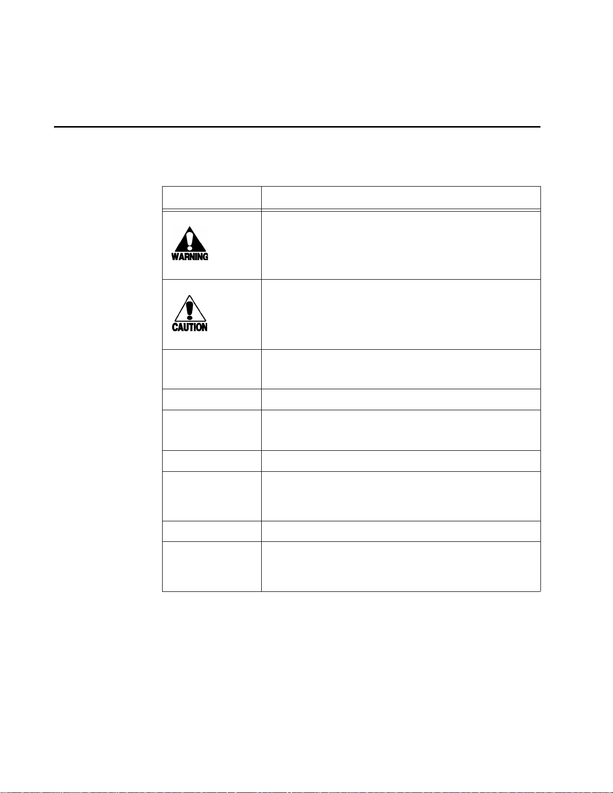
Table 1-2 Typographical Conventions
Convention Indication
This procedure might cause harm to the equipment and/or
the user.
Concerns about a procedure.
Code
Dialog Box Title
Function
Menu Item
Note
NUL Zero-value ASCII character or a zero-value byte.
NULL Zero-value pointers. Null-terminated string refers to strings
Code, including keywords and variables within text and as
separate paragraphs, and user-defined program elements
within text appear in courier typeface.
Title of a dialog box as it appears on screen.
Start with the characters, G4, and are in mixed case with no
underscores, and include parentheses after the name, as in
G4FunctionName().
Appears on a menu. Capitalization follows the interface.
Auxiliary information that further clarifies the current
discussion. These important points require the user’s
attention. The paragraph is in italics and the word Note is
bold.
of printable ASCII characters with a zero-value byte placed
in memory directly after the last printable character of the
string.
1-4
Page 13

2
Overview
Page 14

Page 15

Introduction
Chapter 2
Overview
This chapter provides an overview of the AI1401 Reader and the system
and technology it supports.
The microprocessor-controlled, single output channel AI1401 Reader is an independent unit that combines a reader and a radio frequency (RF) source. The reader provides RF identification (RFID) and data storage within a single, compact unit (Figure
2-1). Due to its size and battery-powered operation, the AI1401 Reader is an invaluable component of any portable reader system.
Figure 2-1 AI1401 Reader
When interfaced with the antenna and power source, the AI1401 Reader uses RF
energy to read data from an electronic tag (a field disturbance device). Tags can con
tain a unique ID code and can be attached to a vehicle, mobile equipment, or shipping
and storage containers. The AI1401 Reader decodes tag ID information and validates
the ID code. Depending on whether you program the reader for buffering or real-time
data transfer, the reader either stores tag data for later processing by a host computer
or transmits the tag data directly to a host computer for real-time data processing and
storage.
-
2-3
Page 16

AI1401 Reader User Guide
System Configuration
The AI1401 Reader is designed to interface with a range of user-supplied handheld
antennas and other equipment for portable applications. A typical portable reader sys
tem consists of a tag that operates within the 915 MHz frequency band, an antenna/
actuator, a direct current (DC) power source, the AI1401 Reader , a host computer , and
communications hardware, for example, RF modems (
-
Figure 2-2).
Figure 2-2 Example of AI1401 Reader System Configuration
The AI1401 Reader is designed to operate using a 13.2V rechargeable NiCad battery
or equivalent DC power source. The reader can store approximately 1,000 tag reads of
128 bits within its 32K buffer. This information may then be transferred to a host
computer. The system also supports real-time reader-to-host communication by
connecting an RF modem to the AI1401 Reader's ASCII RS
or by connecting a PC, handheld, or other computer directly to the reader.
–232C port (Figure 2-3)
2-4
Figure 2-3 ASCII RS–232C Port
Page 17

Overview
Note: The host computer requires software to interpret tag data and to process the
data for storage, retrieval, database manipulation, and records maintenance.Commu
nications (terminal) programs usually do not provide the adequate data processing
capability. Software written specifically for the host computer can be customized to
provide the required capabilities.
System Components and Functions
Components of the AI1401 Reader include:
• Real-time clock
• RS–232C communications port
• Standard DB9 connector for auxiliary input/output (I/O)
• RF channel (915 MHz with SMA-type RF connector for handheld antenna)
• PC board power connector
-
• Power-saving standby mode
• Auxiliary I/O functions (trigger, battery light, lock, etc.)
• Maximum 40-millisecond startup option
When interfaced with the user's antenna and power source and depending upon how
the reader is programmed, the AI1401 Reader provides the following functions:
• Transmits carrier frequency to and receives modulated reflections from tags
within the RF field of the antenna unit.
• Decodes and validates the tag ID information.
• Stores the tag ID code and any appended information for later transmission to the
host computer system.
• Implements real-time reader-to-host communications. You must connect user-sup-
plied RF modems to the AI1401 Reader and remote host computer or connect a
handheld computer terminal to the AI1401 Reader.
Features
This section describes the features of the AI1401 Reader.
Robust Design
The AI1401 Reader is rugged. Surface-mount solid-state circuitry and strain-relief
supports on connectors allow the reader to resist damage from jarring and vibration,
typical conditions in portable applications.
2-5
Page 18

AI1401 Reader User Guide
Memory
The reader's standard 32-Kbyte static random access memory (SRAM) memory holds
approximately 1,000 ID codes. Note that transmitting data to a host computer does not
erase it from the data buffer. A separate command is used to erase all contents of the
buffer, which then turns off the buffer signal.
Tag Compatibility
The AI1401 Reader reads all standard full-frame TransCore 915 MHz band tags,
including read-write tags that have an ATA frame, such as the IT2101 Tag.
Appended Information
Date and time information can be appended to tag ID data for transmission to the host
computer.
Power Supply
The AI1401 Reader uses a 13.2V rechargeable nickel-cadmium (NiCad) battery (not
included) or equivalent DC power source.
Power-Saving Standby Mode
When not in active use, the AI1401 Reader turns off power to all circuitry except the
SRAM and real-time clock. Use of this standby mode extends battery life.
Specifications
Table 2-1 lists the specifications for the AI1401 Reader.
Table 2-1 AI1401 Reader System Specifications
Parameter Specification
Size
Weight
Operating temperature
Power requirements
Power source
Available frequency range
9.0 x 7.5 x 4.5 in
(22.9 x 19.1 x 11.4 cm)
6.0 lb (2.7 kg)
+32°F to +158°F (0°C to +70°C)
+13.5V DC +1.0V DC at 1.3 amps
13.2V, 1.8A NiCad rechargeable battery
(optional) or equivalent DC power source
902–928 MHz
2-6
Approved frequency range by
Federal Communications
Commission (FCC) and Industry
Canada
902.25–903.75 MHz and
910.00–921.50 MHz
Page 19

Table 2-1 AI1401 Reader System Specifications (continued)
Overview
RF power
Typical working range
a
1.6W +0.2W at ambient temperature
Battery tag: 80 ft (24.4 m)
Beam tag: 25 ft (7.6 m)
Buffer size
Data buffer capacity
Communications port
32 Kbytes (battery backed)
1,000 tag reads of 128 bits (with
appended data)
RS–232C
110 to 19,200 Baud
Other features
Real-time calendar clock
Power-saving algorithm
40-ms startup option
a. Depends upon tag type and RF power permitted by FCC licensing requirements.
2-7
Page 20

AI1401 Reader User Guide
2-8
Page 21

3
AI1401 Reader Interface Capabilities
Page 22

Page 23

AI1401 Reader Interface Capabilities
The AI1401 Reader is designed to interface with a variety of user
antennas and other equipment. This chapter outlines the AI1401 Reader
connectors and identifies their primary functions.
AI1401 Connectors
Because the AI1401 Reader combines the system reader and radio frequency (RF)
module into a single unit, the only connections that must be made to the system are the
antenna, actuator, and host computer connectors. These conn ec tors are located at the
end of the AI1401 Reader. (See Figure 2-1 for the location of the connectors.)
3-1 identifies the connectors and their purposes.
Chapter 3
Figure
Figure 3-1 AI1401 Reader Connector Panel
RS–232C Interface
The RS–232C interface connector is a standard DB9 socket connector used for host
computer communications.
Typically, during operation, a portable reader system using the AI1401 Reader functions in the real-time disabled operating mode. In the real-time disabled mode, tag
identifications (ID) are read and stored in the buffer of the AI1401 Reader. After read
ing and storing all tag data, you can connect the AI1401 Reader to a host computer via
the reader's standard RS
software, the contents of the buffer can then be transmitted to the host computer.
–232C connector. Using customized host communications
3-3
-
Page 24

AI1401 Reader User Guide
The RS–232C connector can also be used during system operation, if real-time communications are required. Using the RS–232C connector, the AI1401 Reader supports
the following real-time methods of operation:
• AI1401 Reader to host using direct RS–232C cable connection
• AI1401 Reader to host using RF modems from the remote location to the base
• AI1401 Reader to on-site handheld computer via an RS–232C cable connection
Figure 3-2 defines the pin positions of the RS–232C connector.
location
Figure 3-2 RS–232C DB9 Connector Pin-out
Auxiliary Input/Output Connector
The user's input/output (I/O) interface must provide a DB9 plug connector to terminate on the AI1401 Reader. The user must provide an actuator signal (trigger) that
turns on RF power for reading tags. After tag data is acquired, RF power should be
shut off to conserve power.
Note: When connecting the 10-1401-01 Reader or the 10-1401-04 Reader to a terminal emulator, you may need to isolate Pin 9 of the I/O interface cable.
3-4
Page 25

AI1401 Reader Interface Capabilities
Figure 3-3 illustrates the pin-outs for the I/O interface DB9 connector.
Figure 3-3 I/O Interface DB9 Connector Pin-out
The output signals on the I/O interface DB9 connector indicate operation status of the
AI1401 Reader. These signals can be used to operate LED devices. The AI1401
Reader supports the following signals.
Power (PWR)
The power signal lights when power is applied to the reader unit via the user's RF
actuator switch (trigger). To begin communicating with the reader, you must send a
command within 10 seconds of triggering the device. Commands are discussed in
Chapter 4 of this guide.
After initial power-up, the AI1401 Reader remains on if there is any RS–232C port
activity. Reader power turns off after 10 seconds of inactivity from either the actuator
switch or the RS
value. The user can change the time-out to one minute using the !751 command.
–232C port. The 10-second power off time-out is a factory default
Battery (BATT)
The battery signal is active when the main battery voltage drops below the preset level
(usually about 12.5 volts).
If the battery voltage drops below a second preset level (usually about 11.5 volts), the
microcontroller halts reader functions to prevent improper operation.
Buffer (BUFF)
The buffer signal is active whenever valid data is stored in the data buffer.
Transmitting data to a host computer will not erase it from the data buffer. Command
!73 clears the buffer contents and turns off the buffer LED.
Error (ERR)
The error signal is active when the tag just read contains a parity error.
Lock (LOCK)
The lock signal is active briefly when a valid tag has been decoded.
After the successful acquisition of a tag that meets uniqueness criteria, the RF source
turns off.
3-5
Page 26

AI1401 Reader User Guide
Valid Tag (VAL/TAG)
After successful acquisition of a tag ID, the valid tag signal is active continuously
while the antenna signal is active.
When the antenna signal is deactivated and after a power-on time out, all signals are
off. The power-on time out factory setting is 10 seconds.
Ground (GND)
Ground pin for the DB9 connector
Trigger (TRIG)
Actuator signal that turns on RF power
RF Connector
The user's I/O interface/actuator contains an antenna that broadcasts the RF signal
generated by the RF module and retrieves the amplitude-modulated return signal from
the tag. In addition to the DB9 connector described earlier, the I/O interface must also
provide a SMA-type connector to terminate the RF connection to the AI1401 Reader.
Power
The power connector should be designed to connect to an AMP P/N 643226-1 connector. Power connections should be made as shown in Figure 3-4.
Figure 3-4 Portable Reader Power Connection
3-6
Page 27

A
Firmware Command Groups and
Parameters
Page 28

Page 29

This chapter discusses the firmware command codes, which allow the
user to configure the reader for communications with a personal
computer (PC) or other host computer.
Command Syntax
Command codes enable you to use the features of the AI1401 Reader and to develop
host computer programs for controlling the functions of the AI1401 Reader.
The general syntax of all commands begins with an exclamation character (!) followed by the command code and a list of parameters. No spaces exist between characters, and the command is terminated with Enter or a carriage return <CR>.
As characters are sent to the AI1401 Reader they are automatically echoed back to the
host. As soon as the command is terminated with Enter or <CR>, the AI1401 Reader
responds to the command with one of the following responses:
Appendix A
Firmware Command Groups and
Parameters
!Done — if the command is recognized and accepted
!Error — if it is not recognized
The most typical response is !Done. Other responses are indicated as part of the command descriptions.
Factory default value commands are shown in bold followed by (factory setting).
Command Groups
Reader commands are divided by primary function into eight groups. Following is a
list of the eight command groups:
• Group 1 — Communication Port Control
• Group 2 — Real-Time Clock
• Group 3 — ID Data Format
• Group 4 — This command group not used by AI1401 Reader
• Group 5 — This command group not used by AI1401 Reader
• Group 6 — Interrogator Control
A-3
Page 30

AI1401 Reader User Guide
• Group 7 — Buffer Control
• Group 8 — This command group not used by AI1401 Reader
Command Group 1 — Communication Port Control
Group 1 commands configure the communications parameters used by the se ria l c ommunication port.
The user can set baud rate, stop bits, parity, and end-of-line delay using Command
Group 1 commands.
Baud Rate Select
!100x
where x = 0 to 6
0 = 110 baud
1 = 300 baud
2 = 1200 baud
3 = 2400 baud
4 = 4800 baud
5 = 9600 baud (factory setting)
6 = 19.2 K baud
Response
!Done
or
!Error
Note: The new baud rate setting takes effect after the host computer receives the
!Done response from the reader. All subsequent communications will be at the new
baud rate.
Stop Bits
!101x
A-4
where x = 0 or 1
0=1 stop bit (factory setting)
1 = 2 stop bits
Response
Page 31

Firmware Command Groups and Parameters
!Done
or
!Error
Note: The new stop bits setting takes effect after the host computer receives the !Done
response from the reader. All subsequent communications will be at the new stop bits
setting.
Parity Select
!102x
where x = 0 to 2
0 = disable parity (factory setting)
1 = enable even parity
2 = enable odd parity
Response
!Done
or
!Error
Note: The new parity select setting takes effect after the host computer receives the
!Done response from the reader. All subsequent communications will be at the new
parity setting.
Command Group 2 — Real-Time Clock Control
Group 2 commands control the real-time clock, which maintains the time and date.
The user can set or display the time and date using Group 2 commands.
The real-time clock is supported by an internal lithium battery so that time and date
are preserved in case of power outage. The minimum life expectancy of the battery is
five years, and the battery has a typical life expectancy of 19 years.
Set the Time in the Real-time Clock
!20hh:mm:ss
where
hh = hours (00-23)
mm = minutes (00-59)
ss = seconds (00-59)
Note: Enter the time exactly as shown with no spaces between characters. All entries
use decimal characters 0 through 9.
A-5
Page 32

AI1401 Reader User Guide
Response
!Done
or
!Error
Set the Date in the Real-time Clock
!21MM/DD/YY
where
MM = months (01-12)
DD = days (01-31)
YY = years (00-99)
Note: Enter the date exactly as shown with no spaces between characters. Use forward slashes (/) as delimiters. All entries use decimal characters 0 through 9.
Response
!Done
or
!Error
Display Time and Date
!22
Response
!hh:mm:ss.dd MM/DD/YY
where
hh = hours
mm = minutes
ss = seconds
dd = hundredths of seconds
MM = months
DD = days
A-6
YY = years
Note: There are two spaces between time and date. Use forward slashes (/) as delimiters.
or
!Error
Page 33

Firmware Command Groups and Parameters
Command Group 3 — ID Data Format
Group 3 commands append useful information to reader transmissions such as IDs
and times and dates. Group 3 commands also switch on and off host computer trans
missions. The reader is set at the factory not to append time and date to data.
Do Not Append Time and Date to Data
!300 (factory setting)
The format of the displayed data is
<som><20 chrs><eom>
where
som = start of message character, (!)
20 chrs = 20 data characters
eom = end of message character
-
Response
!Done
or
!Error
Appends Time and Date to Data
!302
The format of the displayed data is
<som><20 chrs><%hh.mm.ss.dd%MM/DD/YY><eom>
where
som = start of message character, (!)
20 chrs = 20 data characters
eom = end of message character
% = time and date string delimiter
hh.mm.ss.dd = see time command !20
MM/DD/YY = see date command !21
Disables Real-Time Transmission to Host
!304
Any acquired tag ID via the RF source is stored in the data buffer and is not sent out
the RS–232C port.
A-7
Page 34

AI1401 Reader User Guide
Response
!Done
or
!Error
Enables Real-Time Transmission to Host
!305 (factory setting)
When a tag is acquired via the RF source, its ID is immediately sent out on the RS–
232C port. The tag ID is not stored in the data buffer. Previously stored data, while in
the non-transmission mode (command !304), is retained and not cleared from the data
buffer.
Response
!Done
or
!Error
Disables Uniqueness Mode
!306
The reader acquires and stores (or sends to the RS–232C port) the same tag ID when
the user-provided RF actuator on the reader is pressed. Uniqueness of tag IDs is not
maintained while in this mode.
Response
!Done
or
!Error
Enables Uniqueness Mode
!307 (factory setting)
Tag ID uniqueness is maintained while in this mode. At least one unique tag ID must
be read before the previously acquired tag ID reads and is stored again.
Response
!Done
or
!Error
A-8
Page 35

Firmware Command Groups and Parameters
Command Group 6 — Interrogator Control
Group 6 commands enable basic protocol or enable transmitter or hardware flow control.
Basic Protocol Enabled (disable all flow control)
!610 (factory setting)
Response
!Done
or
!Error
XON/XOFF Flow Control Enabled
!6140
Response
!Done
or
!Error
Hardware Flow Control Enabled
!6141
The reader controls the data terminal ready line and monitors the readiness of the
modem (or similar external RS
–232C device) via the clear to send (CTS) line. When
the CTS line goes false, the reader halts transmission within one character of the time
that the command is received.
Response
!Done
or
!Error
Command Group 7 — Buffer Control
Group 7 commands control the reader’s search control functions when performed
through the MAIN port.
Display One Line of Data from the Reader Data Buffer
!70
A-9
Page 36

AI1401 Reader User Guide
The reader displays the next line of data from its data buffer. The data pointer then
advances to the next location of data. The data is not erased and continues to be avail
able for display.
Response
<next line of data>
or
!Error — if there is no more valid data to be displayed
Display the Remaining Contents of the Data Buffer
!71
The reader starts with the current location of the data pointer and displays all data until
the last valid data entry. The data is not erased and continues to be available for dis
play.
Response
-
-
Up to 1,000 lines of data, depending on the present position of the data poi nter and the
total number of data entries
or
!Error — if there is no more valid data to display
Reset Data Buffer Pointer to the Beginning
!72
Resets the data pointer to the beginning of the buffer. Resetting allows the displaying
of the data buffer contents as often as needed.
Response
!Done
or
!Error
Clear the Contents of the Data Buffer
!73
Clears all valid data entries from the data buffer and resets the data pointer.
A-10
Request the Number of Entries in the Data Buffer
!74
The number returned is the number of valid data buffer entries in the range of 0 to
1000.
Page 37

Firmware Command Groups and Parameters
Response
!xxxx
where
xxxx = four-digit decimal number, in the range of 0000 to 1000
Note: This number does not give an indication of the position of the display data
pointer.
or
!Error
Set Reader Power-off Time-out to 10 Seconds
!750 (factory setting)
This time-out is the amount of idle time that elapses before the reader discontinues
operation. Activity on the RS
–232C port or activating the trigger signal restarts the
timer.
Response
!Done
or
!Error
Set Reader Power-off Time-out to One Minute
!751
This time-out is the amount of idle time that elapses before the reader discontinues
operation. Activity on the RS
–232C port or activating the trigger signal restarts the
timer.
Response
!Done
or
!Error
Set RF Power-off Time-out
!76x
Sets the amount of time the RF source stays on. The RF source is turned off after the
time-out expires or when the successful acquisition of a tag ID occurs.
where x is
A-11
Page 38

AI1401 Reader User Guide
0 = feature disabled (operates continuous RF mode)
1=50 ms
2 = 100 ms
3 = 200 ms
4 = 300 ms
5 = 400 ms
6 = 500 ms
7 = 600 ms
8 = 700 ms
9 = 800 ms
A = 900 ms
B=1 s (factory setting)
C=2 s
D=3 s
E=4 s
F=5 s
Response
!Done
or
!Error
A-12
Page 39

B
AI1401 Character Conversion
Page 40

Page 41

AI1401 Character Conversion
TransCore Character Conversion Table
Table B-1 lists the TransCore 6-bits per character conversion from the standard ASCII
character set.
Table B-1 ASCII to 6 Bits/Character Conversion Table
ASCII to 6 Bits Per Character Conversions
spc 000000 6 010110 L 101100
! 000001 7 010111 M 101101
" 000010 8 011000 N 101110
# 000011 9 011001 O 101111
$ 000100 : 011010 P 110000
Appendix B
% 000101 ; 011011 Q 110001
& 000110 < 011100 R 110010
’ 000111 = 011101 S 110011
( 001000 > 011110 T 110100
) 001001 ? 011111 U 110101
* 001010 @ 100000 V 110110
+ 001011 A 100001 W 110111
, 001100 B 100010 X 111000
- 001101 C 100011 Y 111001
. 001110 D 100100 Z 111010
/ 001111 E 100101 [ 111011
0 010000 F 100110 \ 111100
1 010001 G 100111 ] 111101
2 010010 H 101000 ^ 111110
3 010011 I 101001 _ 111111
4 010100 J
5 010101 K
B-3
Page 42

AI1401 Reader User Guide
B-4
 Loading...