

Page 1

Encompass® 4H Reader System
TransCore
8600 Jefferson Street NE
Albuquerque, New Mexico 87113
March 2016
P/N 16-0038-002
Page 2

Encompass 4H Reader System Guide
For comments or questions about this document, e-mail tech.pubs@transcore.com.
Information in this document is subject to change and does not represent a commitment on the part of
TransCore, LP.
© 2015-2016 TransCore, LP. All rights reserved. TRANSCORE, AMTECH, EGO, and ENCOMPASS are
registered trademarks and are used under license. All other trademarks are the property of their respective
owners. Contents are subject to change. Printed in the U.S.A.
For further information, contact:
TransCore
8600 Jefferson Street NE
Albuquerque, New Mexico 87113 USA
Technical Support
Phone: (505) 856-8007
Web: transcore.com/rfidsupport
ii
Page 3

Encompass 4H Reader System Guide
FCC RADIO FREQUENCY INTERFERENCE STATEMENT
47 CFR §15.105(a)
NOTE: This equipment has been tested and found to comply with the limits for a Class A digital device
pursuant to Part 15 of the FCC rules. These limits are designed to provide reasonable protection against
harmful interference when the equipment is operated in a commercial environment. This equipment
generates, uses, and can radiate RF energy and may cause harmful interference to radio communications if
not installed and used in accordance with the instruction manual. Operating this equipment in a residential
area is likely to cause harmful interference, in which case, depending on the laws in effect, the user may be
required to correct the interference at their own expense.
NO UNAUTHORIZED MODIFICATIONS
47 CFR §15.21
CAUTION: This equipment may not be modified, altered, or changed in any way without permission
from TransCore, LP. Unauthorized modification may void the equipment authorization from the FCC and
will void the TransCore warranty.
USE OF SHIELDED CABLES IS REQUIRED
47 CFR §15.27(a)
NOTE: Shielded cables must be used with this equipment to comply with FCC regulations.
INDUSTRY CANADA COMPLIANCE STATEMENT
RSS 247
This device complies with Industry Canada’ s license-exempt RSSs. Operation is subject to the following
two conditions:
(1) This device may not cause interference; and
(2) This device must accept any interference, including interference that may cause undesired operation of
the device.
TransCore, LP
USA
NOTE: For IEC60950 compliance, this unit must be used in conjunction with a certified limited power
source (LPS). The LPS should be rated for 16-20VAC output voltage, 3Amps maximum output current or
16-28VDC 3Amps maximum output current, and limited to less than 100VA apparent power.
iii
Page 4

Encompass 4H Reader System Guide
DÉCLARATION SUR LE BROUILLAGE RADIOÉLECTRIQUE, CONFORMÉMENT AUX
EXIGENCES DE LA FCC
47 CFR §15.105(a)
NOTE : Cet appareil a été testé et jugé conforme aux limites établies pour un dispositif numérique de classe A,
selon la partie 15 des règlements de la FCC. Ces limites visent à assurer un degré raisonnable de protection
contre le brouillage préjudiciable lorsque l’appareil est utilisé dans un environnement commercial. Cet appareil
génère, utilise et peut diffuser de l’énergie sous forme de radiofréquences (RF) et peut causer un brouillage
préjudiciable aux communications radio s’il n’est pas installé conformément au mode d’emploi. L’utilisation
de cet appareil en zone résidentielle est susceptible de causer un brouillage préjudiciable, auquel cas, selon la
réglementation applicable, l’utilisateur pourrait être tenu d'éliminer le signal parasite à ses propres frais.
AUCUNE MODIFICA TION SANS AUTORISATION
47 CFR §15.21
MISE EN GARDE: Cet appareil ne peut en aucune façon être modifié, altéré ou transformé sans l’autorisation
de TransCore, LP. Toute modification non autorisée pourrait invalider l’autorisation de la FCC au regard de
l’appareil et annulera la garantie de T ransCore.
UTILISATION DE CÂBLES BLINDÉS ET MISE À LA TERRE
47 CFR §15.27(a)
NOTE : Il est recommandé d’utiliser des câbles blindés et de mettre l’appareil à la terre pour assurer la
conformité aux règlements de la FCC.
INDUSTRIE CANADA DÉCLARATION DE CONFORMITÉ
RSS 247
Le présent appareil est conforme aux CNR d'Industrie Canada applicables aux appareils radio
exempts de licence. L'exploitation est autorisée aux deux conditions suivantes :
(1) l'appareil ne doit pas produire de brouillage, et
(2) l'utilisateur de l'appareil doit accepter tout brouillage radioélectrique subi, même si le brouillage
est susceptible d'en compromettre le fonctionnement.
TransCore, LP
États-Unis
iv
Page 5

Encompass 4H Reader System Guide
Health Limits for Encompass 4H Reader Using Integrated Antenna (902 to 928 MHz)
Within the United States, environmental guidelines regulating safe exposure levels are issued by the Occupational Safety and Health Administration (OSHA).
Section 1910.97 of OSHA Safety and Health Standards 2206 legislates a maximum safe exposure limit of 10 milliwatts per square centimeter (mW/cm
aged over 6 minutes at 915 MHz.
Although not binding, other organizations such as the American National Standards Institute (ANSI) and Health Canada Safety Code 6 (2009) have issued similar guidelines that are more restrictive than the OSHA limits (ANSI C95.1).
Health Canada Safety Code 6 guidelines recommend a maximum safe power den-
sity in W/m
2
, 0.02619ƒ
Thus, the maximum permissible exposure for general population/ uncontrolled
exposure at 915 MHz is 2.77 W/m
The RF power density generated by the Encompass 4H Reader was calculated
using a maximum antenna gain of 11 dBi, equivalent to the antenna gain of the
integrated antenna.
Warning
At 0.291 W transmitted power and a distance of 13 inches (33 cm) from the
reader, the maximum power density calculated was less than 2.77 W/m
the reader at least 13 inches (33 cm) from the general public. Maintenance personnel must remain at least 4.8 inches (12.3 cm) from reader when system is
operating.
0.6834
.
2
. The power limit is a six-minute average.
2
) aver-
2
. Install
The data confirms that the TransCore Encompass 4H Reader effectively meets
OSHA requirements and thus does not represent an operating hazard to either the
general public or maintenance personnel.
v
Page 6

Encompass 4H Reader System Guide
Limites d’innocuité du lecteur Encompass 4H utilisé avec une antenne interne (902 à 928 MHz)
Aux États-Unis, les directives environnementales concernant les niveaux d’exposition
acceptables sont émises par l’OSHA (Occupational Safety and Health Administration).
L’article 1910.97 de la norme de santé et de sécurité 2206 de l’OSHA
d’exposition acceptable à une moyenne de 10 milliwatts par centimètre carré (mW/
2
cm
) sur une période de 6 minutes à 915 MHz.
D’autres organismes de normalisation tels
Institute) et le Code de sécurité 6 de Santé Canada ont émis des directives similaires,
mais non obligatoires, qui fixent des limites plus restrictives que celles de l’OSHA
(notamment la norme ANSI C95.1). Les normes de Santé Canada Code de sécurité 6
recommandent de ne pas dépasser la densité de puissance suivante, exprimée en
2
0,02619ƒ
W/m
Ainsi, le niveau maximal d’exposition permis pour la population générale et les situations d’exposition non contrôlée à 915 MHz est de 2,77 W/m
période de 6 minutes.
La densité de puissance des RF générées par le lecteur Encompass
culée pour un gain d’antenne maximal de 11,0 dBi, soit l’équivalent du gain de
antenne interne.
Mise en garde
Avec une puissance transmise de 0,291 W, la densité de puissance maximale calculée à 13 pouces (33 cm) de l’antenne était inférieure à 2,77 W/m
précaution, installer l’antenne à au moins 13 pouces (33 cm) de la population générale. Le personnel d’entretien doit se tenir à au moins 4.8 pouces (12,3 cm) de
l’antenne lorsque
0,6834
le système est en cours d’utilisation.
que l’ANSI (American National Standards
2
en moyenne sur une
fixe la limite
4H utilisé a été cal-
2
. Par mesure de
vi
Les données confirment que l’utilisation de
exigences de l’OSHA et ne présente pas de danger lié à son utilisation, que ce soit
p
our la population générale ou le personnel d’entretien.
Encompass 4H utilisé répond aux
Page 7

Encompass 4H Reader System Guide
Summary of Revisions to Encompass 4H Reader System Guide
Version
Number
N/A 05/15 Entry for baseline
002 3/16 Added information about power source. Minor updates Chap 7 and 8, Appendix D
Date
Revised
Summary of Changes
vii
Page 8

Encompass 4H Reader System Guide
viii
Page 9

Health Limits for Encompass 4H Reader Using
Integrated Antenna (902 to 928 MHz). . . . . . . . . . . . . . . . . . . . . . . . . . . . . . . . . . . . 1-v
Limites d’innocuité du lecteur Encompass 4H utilisé avec une antenne interne
(902 à 928 MHz) . . . . . . . . . . . . . . . . . . . . . . . . . . . . . . . . . . . . . . . . . . . . . . . . . . . . . 1-vi
Summary of Revisions to Encompass 4H Reader System Guide. . . . . . . . . . . . 1-vii
List of Figures . . . . . . . . . . . . . . . . . . . . . . . . . . . . . . . . . . . . . . . . . . . . . . . . . . . . . 1-xix
List of Tables . . . . . . . . . . . . . . . . . . . . . . . . . . . . . . . . . . . . . . . . . . . . . . . . . . . . . . 1-xxi
1 Introduction
Purpose. . . . . . . . . . . . . . . . . . . . . . . . . . . . . . . . . . . . . . . . . . . . . . . . . . . . . . . . . . . . 1-3
Audience. . . . . . . . . . . . . . . . . . . . . . . . . . . . . . . . . . . . . . . . . . . . . . . . . . . . . . . . . . . 1-3
System Guide Organization . . . . . . . . . . . . . . . . . . . . . . . . . . . . . . . . . . . . . . . . . . . 1-3
Typographical Conventions . . . . . . . . . . . . . . . . . . . . . . . . . . . . . . . . . . . . . . . . . . . 1-5
System Description . . . . . . . . . . . . . . . . . . . . . . . . . . . . . . . . . . . . . . . . . . . . . . . . . . 1-5
Reader. . . . . . . . . . . . . . . . . . . . . . . . . . . . . . . . . . . . . . . . . . . . . . . . . . . . . . . . . . . 1-6
Tags. . . . . . . . . . . . . . . . . . . . . . . . . . . . . . . . . . . . . . . . . . . . . . . . . . . . . . . . . . . . . 1-6
How It Works. . . . . . . . . . . . . . . . . . . . . . . . . . . . . . . . . . . . . . . . . . . . . . . . . . . . . . 1-6
Technical Support . . . . . . . . . . . . . . . . . . . . . . . . . . . . . . . . . . . . . . . . . . . . . . . . . . . 1-7
2 Developing the Site Plan
Overview . . . . . . . . . . . . . . . . . . . . . . . . . . . . . . . . . . . . . . . . . . . . . . . . . . . . . . . . . . . 2-3
Reading of Mixed Population Tags . . . . . . . . . . . . . . . . . . . . . . . . . . . . . . . . . . . . . 2-3
Reader and Tag Alignment . . . . . . . . . . . . . . . . . . . . . . . . . . . . . . . . . . . . . . . . . . . . 2-4
Polarization . . . . . . . . . . . . . . . . . . . . . . . . . . . . . . . . . . . . . . . . . . . . . . . . . . . . . . . 2-5
Unobstructed Line of Sight . . . . . . . . . . . . . . . . . . . . . . . . . . . . . . . . . . . . . . . . . . . 2-6
Site Layout and Traffic Flow . . . . . . . . . . . . . . . . . . . . . . . . . . . . . . . . . . . . . . . . . . . 2-8
The Encompass 4H Reader Read Zone . . . . . . . . . . . . . . . . . . . . . . . . . . . . . . . . . 2-9
Other Encompass 4 Readers in the Area . . . . . . . . . . . . . . . . . . . . . . . . . . . . . . . . 2-9
Lane Configurations . . . . . . . . . . . . . . . . . . . . . . . . . . . . . . . . . . . . . . . . . . . . . . . . 2-9
Gate with Center Island Configuration . . . . . . . . . . . . . . . . . . . . . . . . . . . . . . . 2-10
Parking Garage with Ticket Island Configuration . . . . . . . . . . . . . . . . . . . . . . . 2-11
Overhead Reader Installation Configuration. . . . . . . . . . . . . . . . . . . . . . . . . . . 2-11
Lane Configurations for Encompass 4H Readers. . . . . . . . . . . . . . . . . . . . . . . . . 2-12
vii
Page 10

Encompass 4H Reader System Guide
Reflection, Refraction, and Diffraction of RF Signals . . . . . . . . . . . . . . . . . . . . . . 2-12
Existing Interference . . . . . . . . . . . . . . . . . . . . . . . . . . . . . . . . . . . . . . . . . . . . . . . 2-13
Electrical and Communications Requirements. . . . . . . . . . . . . . . . . . . . . . . . . . . 2-13
Junction Box . . . . . . . . . . . . . . . . . . . . . . . . . . . . . . . . . . . . . . . . . . . . . . . . . . . . . 2-13
Power and Communications Cables. . . . . . . . . . . . . . . . . . . . . . . . . . . . . . . . . . . 2-13
Electrical Power . . . . . . . . . . . . . . . . . . . . . . . . . . . . . . . . . . . . . . . . . . . . . . . . 2-14
Power Extension . . . . . . . . . . . . . . . . . . . . . . . . . . . . . . . . . . . . . . . . . . . . . 2-14
Host Communications. . . . . . . . . . . . . . . . . . . . . . . . . . . . . . . . . . . . . . . . . . . . . . 2-15
RS–232 Interface . . . . . . . . . . . . . . . . . . . . . . . . . . . . . . . . . . . . . . . . . . . . . . . 2-17
RS–422 Interface . . . . . . . . . . . . . . . . . . . . . . . . . . . . . . . . . . . . . . . . . . . . . . . 2-17
Wiegand Interface. . . . . . . . . . . . . . . . . . . . . . . . . . . . . . . . . . . . . . . . . . . . . . . 2-17
Input/Output Circuits . . . . . . . . . . . . . . . . . . . . . . . . . . . . . . . . . . . . . . . . . . . . . . . 2-18
3 Choosing, Installing, and Removing Tags
Compatible Tag Types. . . . . . . . . . . . . . . . . . . . . . . . . . . . . . . . . . . . . . . . . . . . . . . . 3-3
Reader and Tag Model Interoperability. . . . . . . . . . . . . . . . . . . . . . . . . . . . . . . . . . 3-3
TransCore’s eGo Plus Tags . . . . . . . . . . . . . . . . . . . . . . . . . . . . . . . . . . . . . . . . . . 3-4
eGo Plus Sticker Tag . . . . . . . . . . . . . . . . . . . . . . . . . . . . . . . . . . . . . . . . . . . . . . . 3-4
eGo Plus Security Sticker Tag . . . . . . . . . . . . . . . . . . . . . . . . . . . . . . . . . . . . . . . . 3-5
eGo Plus License Plate Tag . . . . . . . . . . . . . . . . . . . . . . . . . . . . . . . . . . . . . . . . . . 3-5
TransCore’s eGo Tags . . . . . . . . . . . . . . . . . . . . . . . . . . . . . . . . . . . . . . . . . . . . . . 3-6
eGo Windshield Sticker Tag . . . . . . . . . . . . . . . . . . . . . . . . . . . . . . . . . . . . . . . . . . 3-6
eGo License Plate Tag . . . . . . . . . . . . . . . . . . . . . . . . . . . . . . . . . . . . . . . . . . . . . . 3-7
Installing eGo Plus Sticker Tags . . . . . . . . . . . . . . . . . . . . . . . . . . . . . . . . . . . . . . . 3-7
Required Materials . . . . . . . . . . . . . . . . . . . . . . . . . . . . . . . . . . . . . . . . . . . . . . . . . 3-8
Positioning eGo Plus Sticker Tags . . . . . . . . . . . . . . . . . . . . . . . . . . . . . . . . . . . . . 3-8
Mirror Post Attached on Windshield . . . . . . . . . . . . . . . . . . . . . . . . . . . . . . . . . . 3-8
Mirror Post Attached on Header. . . . . . . . . . . . . . . . . . . . . . . . . . . . . . . . . . . . . 3-8
Large Truck with No Inside Mirror. . . . . . . . . . . . . . . . . . . . . . . . . . . . . . . . . . . . 3-9
eGo Plus Sticker Tag Installation Procedures. . . . . . . . . . . . . . . . . . . . . . . . . . . . . 3-9
Removing eGo Plus Sticker Tags . . . . . . . . . . . . . . . . . . . . . . . . . . . . . . . . . . . . . . 3-10
Installing eGo Plus Security Sticker Tags. . . . . . . . . . . . . . . . . . . . . . . . . . . . . . . 3-11
eGo Plus Security Sticker Tag Installation Procedures. . . . . . . . . . . . . . . . . . . . . 3-11
Removing eGo Plus Security Sticker Tags . . . . . . . . . . . . . . . . . . . . . . . . . . . . . . 3-12
Installing eGo Plus License Plate Tags . . . . . . . . . . . . . . . . . . . . . . . . . . . . . . . . . 3-13
Required Materials . . . . . . . . . . . . . . . . . . . . . . . . . . . . . . . . . . . . . . . . . . . . . . . . 3-13
Positioning eGo Plus License Plate Tags . . . . . . . . . . . . . . . . . . . . . . . . . . . . . . . 3-13
eGo Plus LPT Installation Procedures . . . . . . . . . . . . . . . . . . . . . . . . . . . . . . . . . 3-13
Installing eGo Windshield Sticker Tags. . . . . . . . . . . . . . . . . . . . . . . . . . . . . . . . . 3-15
Required Materials . . . . . . . . . . . . . . . . . . . . . . . . . . . . . . . . . . . . . . . . . . . . . . . . 3-16
viii
Page 11

Positioning eGo Windshield Sticker Tags . . . . . . . . . . . . . . . . . . . . . . . . . . . . . . . 3-16
Mirror Post Attached Low On Windshield. . . . . . . . . . . . . . . . . . . . . . . . . . . . . 3-16
Mirror Post Attached High on Windshield. . . . . . . . . . . . . . . . . . . . . . . . . . . . . 3-16
Mirror Post Attached to Headliner. . . . . . . . . . . . . . . . . . . . . . . . . . . . . . . . . . . 3-17
Mounting the eGo Windshield Sticker Tag . . . . . . . . . . . . . . . . . . . . . . . . . . . . . . 3-17
Removing eGo Windshield Sticker Tags. . . . . . . . . . . . . . . . . . . . . . . . . . . . . . . . 3-18
Installing eGo LPT . . . . . . . . . . . . . . . . . . . . . . . . . . . . . . . . . . . . . . . . . . . . . . . . . . 3-18
Installing Interior ATA Tags . . . . . . . . . . . . . . . . . . . . . . . . . . . . . . . . . . . . . . . . . . 3-18
Required Materials . . . . . . . . . . . . . . . . . . . . . . . . . . . . . . . . . . . . . . . . . . . . . . . . 3-19
Positioning ATA Tags . . . . . . . . . . . . . . . . . . . . . . . . . . . . . . . . . . . . . . . . . . . . . . 3-19
Interior Driver’s or Passenger’s Side . . . . . . . . . . . . . . . . . . . . . . . . . . . . . . . . 3-19
Interior Center Windshield . . . . . . . . . . . . . . . . . . . . . . . . . . . . . . . . . . . . . . . . 3-19
ATA Interior Tag Installation Procedures. . . . . . . . . . . . . . . . . . . . . . . . . . . . . . . . 3-20
Removing Interior ATA Tags. . . . . . . . . . . . . . . . . . . . . . . . . . . . . . . . . . . . . . . . . . 3-21
Installing ATA License Plate Tags . . . . . . . . . . . . . . . . . . . . . . . . . . . . . . . . . . . . . 3-21
Required Materials . . . . . . . . . . . . . . . . . . . . . . . . . . . . . . . . . . . . . . . . . . . . . . . . 3-21
Positioning ATA License Plate Tags. . . . . . . . . . . . . . . . . . . . . . . . . . . . . . . . . . . 3-22
ATA License Plate Tag Installation Procedures . . . . . . . . . . . . . . . . . . . . . . . . . . 3-22
Types of Bumpers . . . . . . . . . . . . . . . . . . . . . . . . . . . . . . . . . . . . . . . . . . . . . . . . . 3-25
Alternate Mounting Locations . . . . . . . . . . . . . . . . . . . . . . . . . . . . . . . . . . . . . . . . 3-25
Required Materials . . . . . . . . . . . . . . . . . . . . . . . . . . . . . . . . . . . . . . . . . . . . . . . . 3-25
Installation Procedures Using Tape. . . . . . . . . . . . . . . . . . . . . . . . . . . . . . . . . . . . 3-26
Installation Procedures Using Blind Rivets . . . . . . . . . . . . . . . . . . . . . . . . . . . . . . 3-26
Removing Exterior Tags . . . . . . . . . . . . . . . . . . . . . . . . . . . . . . . . . . . . . . . . . . . . . 3-26
4 Installing the Encompass 4H Reader
Installation Process. . . . . . . . . . . . . . . . . . . . . . . . . . . . . . . . . . . . . . . . . . . . . . . . . . 4-3
Materials Supplied by TransCore . . . . . . . . . . . . . . . . . . . . . . . . . . . . . . . . . . . . . . 4-3
Contents of Shipping Carton. . . . . . . . . . . . . . . . . . . . . . . . . . . . . . . . . . . . . . . . 4-3
Installation Accessory Options . . . . . . . . . . . . . . . . . . . . . . . . . . . . . . . . . . . . . . 4-4
Additional Materials Needed for Testing . . . . . . . . . . . . . . . . . . . . . . . . . . . . . . . . . 4-4
Pre-installation Testing of the Encompass 4H Reader. . . . . . . . . . . . . . . . . . . . . . 4-4
Testing the Encompass 4H Reader Using an Audible Circuit Tester . . . . . . . . . . . 4-5
Connecting the AC Power Supply. . . . . . . . . . . . . . . . . . . . . . . . . . . . . . . . . . . . . . 4-5
Connecting the DC Power Supply. . . . . . . . . . . . . . . . . . . . . . . . . . . . . . . . . . . . . . 4-6
Connecting Communications for Bench Testing . . . . . . . . . . . . . . . . . . . . . . . . . . . 4-6
Required Materials . . . . . . . . . . . . . . . . . . . . . . . . . . . . . . . . . . . . . . . . . . . . . . . 4-7
Connecting for Bench Testing with RS–232 Interface . . . . . . . . . . . . . . . . . . . . 4-7
Connecting the Encompass 4H Reader Colored-Wire Pair Cable. . . . . . . . . 4-9
ix
Page 12

Encompass 4H Reader System Guide
Connecting for Bench Testing with RS–422 Interface . . . . . . . . . . . . . . . . . . . 4-10
Bench Testing the Encompass 4H Reader Before Installation . . . . . . . . . . . . . . . 4-10
Mounting the Encompass 4H Reader. . . . . . . . . . . . . . . . . . . . . . . . . . . . . . . . . . . 4-12
Mounting the Encompass 4H Reader on a Round Pole . . . . . . . . . . . . . . . . . . . . 4-12
Required Materials To Be Supplied by Customer. . . . . . . . . . . . . . . . . . . . . . . 4-12
Procedures . . . . . . . . . . . . . . . . . . . . . . . . . . . . . . . . . . . . . . . . . . . . . . . . . . . . 4-12
Mounting the Encompass 4H Reader to a Wall or Flat Surface . . . . . . . . . . . . . . 4-16
Required Materials . . . . . . . . . . . . . . . . . . . . . . . . . . . . . . . . . . . . . . . . . . . . . . 4-16
Procedures . . . . . . . . . . . . . . . . . . . . . . . . . . . . . . . . . . . . . . . . . . . . . . . . . . . . 4-16
Connecting the Power Supply. . . . . . . . . . . . . . . . . . . . . . . . . . . . . . . . . . . . . . . . 4-19
Reader Cable Grounding . . . . . . . . . . . . . . . . . . . . . . . . . . . . . . . . . . . . . . . . . . . 4-20
Connecting Communications. . . . . . . . . . . . . . . . . . . . . . . . . . . . . . . . . . . . . . . . . 4-20
Required Materials . . . . . . . . . . . . . . . . . . . . . . . . . . . . . . . . . . . . . . . . . . . . . . . . 4-21
Connecting the Encompass 4H Reader to the PC . . . . . . . . . . . . . . . . . . . . . . . . 4-21
RS–232 Interface . . . . . . . . . . . . . . . . . . . . . . . . . . . . . . . . . . . . . . . . . . . . . . . 4-21
Connecting the Encompass 4H Reader Colored-Wire Pair Cable. . . . . . . . 4-22
RS–422 Interface . . . . . . . . . . . . . . . . . . . . . . . . . . . . . . . . . . . . . . . . . . . . . . . 4-23
Wiegand Interface. . . . . . . . . . . . . . . . . . . . . . . . . . . . . . . . . . . . . . . . . . . . . . . 4-24
Connecting Sense Input and Sense Output Circuits . . . . . . . . . . . . . . . . . . . . . . 4-25
Sense Input Circuits . . . . . . . . . . . . . . . . . . . . . . . . . . . . . . . . . . . . . . . . . . . . . . . 4-25
Sense Output Circuits . . . . . . . . . . . . . . . . . . . . . . . . . . . . . . . . . . . . . . . . . . . . . . 4-27
Marking the Read Zone . . . . . . . . . . . . . . . . . . . . . . . . . . . . . . . . . . . . . . . . . . . . . . 4-30
Required Materials. . . . . . . . . . . . . . . . . . . . . . . . . . . . . . . . . . . . . . . . . . . . . . . . 4-30
Procedures . . . . . . . . . . . . . . . . . . . . . . . . . . . . . . . . . . . . . . . . . . . . . . . . . . . . . . 4-30
5 General Software Information
Command Entry Conventions. . . . . . . . . . . . . . . . . . . . . . . . . . . . . . . . . . . . . . . . . . 5-3
Command Response Conventions. . . . . . . . . . . . . . . . . . . . . . . . . . . . . . . . . . . . . . 5-4
Operating Parameters . . . . . . . . . . . . . . . . . . . . . . . . . . . . . . . . . . . . . . . . . . . . . . . . 5-5
Power Fail. . . . . . . . . . . . . . . . . . . . . . . . . . . . . . . . . . . . . . . . . . . . . . . . . . . . . . . . . . 5-5
Program Download . . . . . . . . . . . . . . . . . . . . . . . . . . . . . . . . . . . . . . . . . . . . . . . . . . 5-5
Download Considerations . . . . . . . . . . . . . . . . . . . . . . . . . . . . . . . . . . . . . . . . . . . . 5-5
Download Procedures. . . . . . . . . . . . . . . . . . . . . . . . . . . . . . . . . . . . . . . . . . . . . . . 5-6
Startup. . . . . . . . . . . . . . . . . . . . . . . . . . . . . . . . . . . . . . . . . . . . . . . . . . . . . . . . . . . . . 5-6
Sign-On Message . . . . . . . . . . . . . . . . . . . . . . . . . . . . . . . . . . . . . . . . . . . . . . . . . . 5-6
Boot Failure Message . . . . . . . . . . . . . . . . . . . . . . . . . . . . . . . . . . . . . . . . . . . . . . . 5-6
Tag/Message Buffer. . . . . . . . . . . . . . . . . . . . . . . . . . . . . . . . . . . . . . . . . . . . . . . . . . 5-7
x
Page 13

6 Communications Protocols
Introduction . . . . . . . . . . . . . . . . . . . . . . . . . . . . . . . . . . . . . . . . . . . . . . . . . . . . . . . . 6-3
Basic Protocol . . . . . . . . . . . . . . . . . . . . . . . . . . . . . . . . . . . . . . . . . . . . . . . . . . . . . . 6-4
Error Correcting Protocol . . . . . . . . . . . . . . . . . . . . . . . . . . . . . . . . . . . . . . . . . . . . . 6-4
Data Inquiry Protocol. . . . . . . . . . . . . . . . . . . . . . . . . . . . . . . . . . . . . . . . . . . . . . . . . 6-5
Basic Protocol and ECP Format. . . . . . . . . . . . . . . . . . . . . . . . . . . . . . . . . . . . . . . . 6-5
Reader Transmissions. . . . . . . . . . . . . . . . . . . . . . . . . . . . . . . . . . . . . . . . . . . . . . . 6-5
ECP Host ACK/NAK Response . . . . . . . . . . . . . . . . . . . . . . . . . . . . . . . . . . . . . . . . 6-6
Switch to Command Mode Request . . . . . . . . . . . . . . . . . . . . . . . . . . . . . . . . . . . . 6-7
Host Transmission. . . . . . . . . . . . . . . . . . . . . . . . . . . . . . . . . . . . . . . . . . . . . . . . . . 6-8
Reader Command Response . . . . . . . . . . . . . . . . . . . . . . . . . . . . . . . . . . . . . . . . . 6-9
Sample Messages. . . . . . . . . . . . . . . . . . . . . . . . . . . . . . . . . . . . . . . . . . . . . . . . . . 6-9
Reader Transmissions . . . . . . . . . . . . . . . . . . . . . . . . . . . . . . . . . . . . . . . . . . . . 6-9
Host Command Transmissions. . . . . . . . . . . . . . . . . . . . . . . . . . . . . . . . . . . . . 6-10
Timing and Synchronization . . . . . . . . . . . . . . . . . . . . . . . . . . . . . . . . . . . . . . . . . 6-11
Reader-Addressed Failure Conditions . . . . . . . . . . . . . . . . . . . . . . . . . . . . . . . . . 6-12
Illegal Sequence Number (not in the range 0–9, A–F) . . . . . . . . . . . . . . . . . . . 6-12
Wrong Sequence Number . . . . . . . . . . . . . . . . . . . . . . . . . . . . . . . . . . . . . . . . 6-12
Incorrect CRC. . . . . . . . . . . . . . . . . . . . . . . . . . . . . . . . . . . . . . . . . . . . . . . . . . 6-13
Illegal Command. . . . . . . . . . . . . . . . . . . . . . . . . . . . . . . . . . . . . . . . . . . . . . . . 6-13
Transmission Timeout . . . . . . . . . . . . . . . . . . . . . . . . . . . . . . . . . . . . . . . . . . . 6-13
Receive Timeout. . . . . . . . . . . . . . . . . . . . . . . . . . . . . . . . . . . . . . . . . . . . . . . . 6-13
Asynchronous Message/Command Message Collision . . . . . . . . . . . . . . . . . . 6-13
Host-Addressed Failure Conditions. . . . . . . . . . . . . . . . . . . . . . . . . . . . . . . . . . . . 6-13
Illegal or Wrong Sequence Number . . . . . . . . . . . . . . . . . . . . . . . . . . . . . . . . . 6-13
Incorrect CRC. . . . . . . . . . . . . . . . . . . . . . . . . . . . . . . . . . . . . . . . . . . . . . . . . . 6-13
Transmission Timeout . . . . . . . . . . . . . . . . . . . . . . . . . . . . . . . . . . . . . . . . . . . 6-13
Receive Timeout. . . . . . . . . . . . . . . . . . . . . . . . . . . . . . . . . . . . . . . . . . . . . . . . 6-14
Asynchronous Message/Command Message Collision . . . . . . . . . . . . . . . . . . 6-14
ECP Reliability . . . . . . . . . . . . . . . . . . . . . . . . . . . . . . . . . . . . . . . . . . . . . . . . . . . . . 6-14
CRC Calculation. . . . . . . . . . . . . . . . . . . . . . . . . . . . . . . . . . . . . . . . . . . . . . . . . . . . 6-14
Manually Disabling ECP for Maintenance . . . . . . . . . . . . . . . . . . . . . . . . . . . . . . . 6-17
7 Commands
Introduction . . . . . . . . . . . . . . . . . . . . . . . . . . . . . . . . . . . . . . . . . . . . . . . . . . . . . . . . 7-3
Operating Modes . . . . . . . . . . . . . . . . . . . . . . . . . . . . . . . . . . . . . . . . . . . . . . . . . . . . 7-3
xi
Page 14

Encompass 4H Reader System Guide
Data Mode. . . . . . . . . . . . . . . . . . . . . . . . . . . . . . . . . . . . . . . . . . . . . . . . . . . . . . . . 7-3
Command Mode . . . . . . . . . . . . . . . . . . . . . . . . . . . . . . . . . . . . . . . . . . . . . . . . . . . 7-4
Download Mode . . . . . . . . . . . . . . . . . . . . . . . . . . . . . . . . . . . . . . . . . . . . . . . . . . . 7-4
Command List . . . . . . . . . . . . . . . . . . . . . . . . . . . . . . . . . . . . . . . . . . . . . . . . . . . . . . 7-5
Reader Mode Control — Command Group 0 . . . . . . . . . . . . . . . . . . . . . . . . . . . . . 7-5
00 Switch to Data Mode (Factory Default) . . . . . . . . . . . . . . . . . . . . . . . . . . . . . 7-5
01 Switch to Command Mode. . . . . . . . . . . . . . . . . . . . . . . . . . . . . . . . . . . . . . . 7-5
Communications Port Control — Command Group 1. . . . . . . . . . . . . . . . . . . . . . . 7-6
100N Select Baud Rate . . . . . . . . . . . . . . . . . . . . . . . . . . . . . . . . . . . . . . . . . . . 7-6
101N Select Stop Bits. . . . . . . . . . . . . . . . . . . . . . . . . . . . . . . . . . . . . . . . . . . . . 7-6
102N Select Parity . . . . . . . . . . . . . . . . . . . . . . . . . . . . . . . . . . . . . . . . . . . . . . . 7-7
Command Group 2 . . . . . . . . . . . . . . . . . . . . . . . . . . . . . . . . . . . . . . . . . . . . . . . . . 7-7
20 Set Time . . . . . . . . . . . . . . . . . . . . . . . . . . . . . . . . . . . . . . . . . . . . . . . . . . . . 7-7
21 Set Date. . . . . . . . . . . . . . . . . . . . . . . . . . . . . . . . . . . . . . . . . . . . . . . . . . . . . 7-8
22 Display Time and Date . . . . . . . . . . . . . . . . . . . . . . . . . . . . . . . . . . . . . . . . . 7-8
Append Information — Command Group 3. . . . . . . . . . . . . . . . . . . . . . . . . . . . . . . 7-8
30N Append Time and Date Selection. . . . . . . . . . . . . . . . . . . . . . . . . . . . . . . . 7-8
31N Append Auxiliary Information Selection . . . . . . . . . . . . . . . . . . . . . . . . . . . 7-9
#320 Disable EAC Page Append (Factory Default) . . . . . . . . . . . . . . . . . . . . . 7-10
#321 Enable EAC Page Append . . . . . . . . . . . . . . . . . . . . . . . . . . . . . . . . . . . 7-10
ID Filtering — Command Group 4. . . . . . . . . . . . . . . . . . . . . . . . . . . . . . . . . . . . . 7-11
40 Transmit All ID Codes . . . . . . . . . . . . . . . . . . . . . . . . . . . . . . . . . . . . . . . . . 7-11
410N Select Unique ID Code Criteria (Anti-passback Feature) . . . . . . . . . . . . 7-11
420N Select Valid ID Code Criteria . . . . . . . . . . . . . . . . . . . . . . . . . . . . . . . . . 7-12
440 Reset Uniqueness. . . . . . . . . . . . . . . . . . . . . . . . . . . . . . . . . . . . . . . . . . . 7-12
44N Set Uniqueness Timeout. . . . . . . . . . . . . . . . . . . . . . . . . . . . . . . . . . . . . . 7-12
450 Disable Wiegand Mode (Factory Default) . . . . . . . . . . . . . . . . . . . . . . . . . 7-13
451 Enable Wiegand Mode . . . . . . . . . . . . . . . . . . . . . . . . . . . . . . . . . . . . . . . 7-13
452 Disable Tag Translation Mode (Factory Default). . . . . . . . . . . . . . . . . . . . 7-13
453 Enable Tag Translation Mode . . . . . . . . . . . . . . . . . . . . . . . . . . . . . . . . . . 7-14
454 Disable Multi-tag Sort (Factory Default). . . . . . . . . . . . . . . . . . . . . . . . . . . 7-14
455 Enable Multi-tag Sort. . . . . . . . . . . . . . . . . . . . . . . . . . . . . . . . . . . . . . . . . 7-14
456 Enable eGo Plus Tag Initialization During Multi-tag Sort (Factory Default) 7-14
457 Disable eGo Plus Tag Initialization During Multi-tag Sort . . . . . . . . . . . . . 7-14
458 Disable Second Alternate Group Select (Factory Default) . . . . . . . . . . . . 7-15
459 Enable Second Alternate Group Select. . . . . . . . . . . . . . . . . . . . . . . . . . . 7-15
480 Disable ATA. . . . . . . . . . . . . . . . . . . . . . . . . . . . . . . . . . . . . . . . . . . . . . . . 7-15
481 Enable ATA . . . . . . . . . . . . . . . . . . . . . . . . . . . . . . . . . . . . . . . . . . . . . . . . 7-15
482 Disable eGo. . . . . . . . . . . . . . . . . . . . . . . . . . . . . . . . . . . . . . . . . . . . . . . . 7-15
483 Enable eGo . . . . . . . . . . . . . . . . . . . . . . . . . . . . . . . . . . . . . . . . . . . . . . . . 7-15
484 Disable SeGo. . . . . . . . . . . . . . . . . . . . . . . . . . . . . . . . . . . . . . . . . . . . . . . 7-16
485 Enable SeGo . . . . . . . . . . . . . . . . . . . . . . . . . . . . . . . . . . . . . . . . . . . . . . . 7-16
486 Disable IAG . . . . . . . . . . . . . . . . . . . . . . . . . . . . . . . . . . . . . . . . . . . . . . . . 7-16
487 Enable IAG . . . . . . . . . . . . . . . . . . . . . . . . . . . . . . . . . . . . . . . . . . . . . . . . 7-16
488 Disable eATA. . . . . . . . . . . . . . . . . . . . . . . . . . . . . . . . . . . . . . . . . . . . . . . 7-16
489 Enable eATA . . . . . . . . . . . . . . . . . . . . . . . . . . . . . . . . . . . . . . . . . . . . . . . 7-16
490 Disable Third Alternate Group Select (Factory Default) . . . . . . . . . . . . . . 7-16
xii
Page 15

491 Enable Third Alternate Group Select. . . . . . . . . . . . . . . . . . . . . . . . . . . . . 7-16
492 Disable Fourth Alternate Group Select (Factory Default) . . . . . . . . . . . . . 7-16
493 Enable Fourth Alternate Group Select. . . . . . . . . . . . . . . . . . . . . . . . . . . . 7-17
494 Disable Fifth Alternate Group Select (Factory Default) . . . . . . . . . . . . . . . 7-17
495 Enable Fifth Alternate Group Select . . . . . . . . . . . . . . . . . . . . . . . . . . . . . 7-17
496 Disable Alternate Group Select (Factory Default) . . . . . . . . . . . . . . . . . . . 7-17
497 Enable Alternate Group Select . . . . . . . . . . . . . . . . . . . . . . . . . . . . . . . . . 7-17
Reader Status — Command Group 5 . . . . . . . . . . . . . . . . . . . . . . . . . . . . . . . . . . 7-18
505 Display Software Version. . . . . . . . . . . . . . . . . . . . . . . . . . . . . . . . . . . . . . 7-18
506 Display Hardware Configuration Information. . . . . . . . . . . . . . . . . . . . . . . 7-18
510 Display RF Transceiver FPGA Version . . . . . . . . . . . . . . . . . . . . . . . . . . . 7-18
511 Display RF Transceiver I Filter Chip Version. . . . . . . . . . . . . . . . . . . . . . . 7-18
512 Display RF Transceiver Q Filter Chip Version. . . . . . . . . . . . . . . . . . . . . . 7-18
513 Display DSP Board Actel Version . . . . . . . . . . . . . . . . . . . . . . . . . . . . . . . 7-18
520 Display Power Fail Bit . . . . . . . . . . . . . . . . . . . . . . . . . . . . . . . . . . . . . . . . 7-18
521 Display Reader ID Number . . . . . . . . . . . . . . . . . . . . . . . . . . . . . . . . . . . . 7-19
522 Display Communications Port Parameters . . . . . . . . . . . . . . . . . . . . . . . . 7-19
524 Display Appended Information Status . . . . . . . . . . . . . . . . . . . . . . . . . . . . 7-20
525 Display Communications Protocol Status . . . . . . . . . . . . . . . . . . . . . . . . . 7-20
526 Display I/O Status . . . . . . . . . . . . . . . . . . . . . . . . . . . . . . . . . . . . . . . . . . . 7-21
527 Display RF Status . . . . . . . . . . . . . . . . . . . . . . . . . . . . . . . . . . . . . . . . . . . 7-23
529 Display Presence Input Status. . . . . . . . . . . . . . . . . . . . . . . . . . . . . . . . . . 7-24
530 Display RF0 Filter Status. . . . . . . . . . . . . . . . . . . . . . . . . . . . . . . . . . . . . . 7-26
532 Display Wiegand Mode Status. . . . . . . . . . . . . . . . . . . . . . . . . . . . . . . . . . 7-27
533 Display Wiegand Retransmit Interval. . . . . . . . . . . . . . . . . . . . . . . . . . . . . 7-27
534 Display Tag Translation Mode Status . . . . . . . . . . . . . . . . . . . . . . . . . . . . 7-27
537 Display Echo Status. . . . . . . . . . . . . . . . . . . . . . . . . . . . . . . . . . . . . . . . . . 7-27
540 Display Flash Checksum. . . . . . . . . . . . . . . . . . . . . . . . . . . . . . . . . . . . . . 7-28
543 Display Boot Checksum. . . . . . . . . . . . . . . . . . . . . . . . . . . . . . . . . . . . . . . 7-28
549 Display User-Programmable Group Select Equals (GSE) Filter Data. . . . 7-28
560 Request Sensor Status Change . . . . . . . . . . . . . . . . . . . . . . . . . . . . . . . . 7-28
570 Display Tag Protocols . . . . . . . . . . . . . . . . . . . . . . . . . . . . . . . . . . . . . . . . 7-29
577 Report Buffered Handshakes . . . . . . . . . . . . . . . . . . . . . . . . . . . . . . . . . . 7-29
#582 Display Synchronization Values . . . . . . . . . . . . . . . . . . . . . . . . . . . . . . . 7-29
Reader Control Functions — Command Group 6 . . . . . . . . . . . . . . . . . . . . . . . . . 7-30
60NN Set Reader ID Number. . . . . . . . . . . . . . . . . . . . . . . . . . . . . . . . . . . . . . 7-30
610 Select Basic Communication Protocol (Factory Default). . . . . . . . . . . . . . 7-30
611 Select Error Correcting Protocol . . . . . . . . . . . . . . . . . . . . . . . . . . . . . . . . 7-30
612NN Select Error Correcting Protocol Timeout. . . . . . . . . . . . . . . . . . . . . . . 7-30
613 Enable Data Inquiry Protocol. . . . . . . . . . . . . . . . . . . . . . . . . . . . . . . . . . . 7-31
614N Select Flow Control Option . . . . . . . . . . . . . . . . . . . . . . . . . . . . . . . . . . . 7-31
6170 Disable Echo Mode . . . . . . . . . . . . . . . . . . . . . . . . . . . . . . . . . . . . . . . . . 7-32
6171 Enable Echo Mode (Factory Default). . . . . . . . . . . . . . . . . . . . . . . . . . . . 7-32
620N Set Output Control . . . . . . . . . . . . . . . . . . . . . . . . . . . . . . . . . . . . . . . . . 7-32
621 Select Predefined Output Control (Factory Default) . . . . . . . . . . . . . . . . . 7-33
63 Reset Reader. . . . . . . . . . . . . . . . . . . . . . . . . . . . . . . . . . . . . . . . . . . . . . . . 7-33
640N RF Control. . . . . . . . . . . . . . . . . . . . . . . . . . . . . . . . . . . . . . . . . . . . . . . . 7-33
641 Select RF-by-Input Control (Factory Default) . . . . . . . . . . . . . . . . . . . . . . 7-34
xiii
Page 16

Encompass 4H Reader System Guide
643NN Select ATA Operating Range (Distance) . . . . . . . . . . . . . . . . . . . . . . . 7-34
644NN Set RF Attenuation . . . . . . . . . . . . . . . . . . . . . . . . . . . . . . . . . . . . . . . 7-34
645NN Set eGo and eGo Plus Operating Range (Distance) . . . . . . . . . . . . . . 7-35
646XX Set IAG RF Attenuation . . . . . . . . . . . . . . . . . . . . . . . . . . . . . . . . . . . . 7-35
#648NN Set Synchronization Output Delay Time. . . . . . . . . . . . . . . . . . . . . . . 7-35
#649NN Set Synchronization Hold Off Time . . . . . . . . . . . . . . . . . . . . . . . . . . 7-36
65 Reset Power Fail Bit . . . . . . . . . . . . . . . . . . . . . . . . . . . . . . . . . . . . . . . . . . 7-37
66F Load Default Operating Parameters . . . . . . . . . . . . . . . . . . . . . . . . . . . . . 7-37
67N Set Output Pulse Duration . . . . . . . . . . . . . . . . . . . . . . . . . . . . . . . . . . . . 7-37
690N Select Presence Without Tag Report Option . . . . . . . . . . . . . . . . . . . . . 7-38
692N Select RF Control Algorithm . . . . . . . . . . . . . . . . . . . . . . . . . . . . . . . . . . 7-39
693N Select RF Timeout Period. . . . . . . . . . . . . . . . . . . . . . . . . . . . . . . . . . . . 7-39
694N Select Input Inversion Option . . . . . . . . . . . . . . . . . . . . . . . . . . . . . . . . . 7-40
695S...S Set Serial Number . . . . . . . . . . . . . . . . . . . . . . . . . . . . . . . . . . . . . . . 7-41
696S...S Store Hardware Configuration String. . . . . . . . . . . . . . . . . . . . . . . . . 7-41
697 Set User-Programmable Group Select Equals (GSE) Filter . . . . . . . . . . . 7-42
Auxiliary Reader Control — Command Group 8. . . . . . . . . . . . . . . . . . . . . . . . . . 7-43
82N Select Input Status Change Report Option. . . . . . . . . . . . . . . . . . . . . . . . 7-43
830 Disable Automatic Periodic RF Status Report (Factory Default). . . . . . . . 7-43
831 Enable Automatic Periodic RF Status Report . . . . . . . . . . . . . . . . . . . . . . 7-43
8 Configuring the Encompass 4H Reader
Configuring the Reader. . . . . . . . . . . . . . . . . . . . . . . . . . . . . . . . . . . . . . . . . . . . . . . 8-3
General Configuration Labeling. . . . . . . . . . . . . . . . . . . . . . . . . . . . . . . . . . . . . . . . 8-3
Default Operating Parameter Settings . . . . . . . . . . . . . . . . . . . . . . . . . . . . . . . . . . 8-4
Configuring Parameters with Terminal Emulation Software . . . . . . . . . . . . . . . . . 8-5
Starting the Terminal Emulation Software. . . . . . . . . . . . . . . . . . . . . . . . . . . . . . . . 8-6
Verifying Communications. . . . . . . . . . . . . . . . . . . . . . . . . . . . . . . . . . . . . . . . . . . . 8-8
Verifying Tag Read Capability. . . . . . . . . . . . . . . . . . . . . . . . . . . . . . . . . . . . . . . . 8-10
Configuring Encompass 4H Parameters . . . . . . . . . . . . . . . . . . . . . . . . . . . . . . . . 8-12
Appended Tag Data . . . . . . . . . . . . . . . . . . . . . . . . . . . . . . . . . . . . . . . . . . . . . . . 8-13
ID Separation . . . . . . . . . . . . . . . . . . . . . . . . . . . . . . . . . . . . . . . . . . . . . . . . . . . . 8-13
Reports . . . . . . . . . . . . . . . . . . . . . . . . . . . . . . . . . . . . . . . . . . . . . . . . . . . . . . . . . 8-13
Reset Reader . . . . . . . . . . . . . . . . . . . . . . . . . . . . . . . . . . . . . . . . . . . . . . . . . . . . 8-14
RF Transmission. . . . . . . . . . . . . . . . . . . . . . . . . . . . . . . . . . . . . . . . . . . . . . . . . . 8-15
Vehicle Detector Controlling RF Transmission. . . . . . . . . . . . . . . . . . . . . . . . . 8-15
Host Controlling RF Transmission . . . . . . . . . . . . . . . . . . . . . . . . . . . . . . . . . . 8-16
Continuous RF Transmission . . . . . . . . . . . . . . . . . . . . . . . . . . . . . . . . . . . . . . 8-16
Sense Inputs . . . . . . . . . . . . . . . . . . . . . . . . . . . . . . . . . . . . . . . . . . . . . . . . . . . . . 8-16
Sense Output Devices. . . . . . . . . . . . . . . . . . . . . . . . . . . . . . . . . . . . . . . . . . . . . . 8-16
Serial Port Communications . . . . . . . . . . . . . . . . . . . . . . . . . . . . . . . . . . . . . . . . . 8-17
Port Configuration Parameters . . . . . . . . . . . . . . . . . . . . . . . . . . . . . . . . . . . . . . . 8-17
Communications Protocol . . . . . . . . . . . . . . . . . . . . . . . . . . . . . . . . . . . . . . . . . . . 8-18
Software Flow Control. . . . . . . . . . . . . . . . . . . . . . . . . . . . . . . . . . . . . . . . . . . . . . 8-18
xiv
Page 17

Fine-Tuning and Verifying the Read Zone. . . . . . . . . . . . . . . . . . . . . . . . . . . . . . . 8-19
Physically Orienting the Encompass 4H Reader . . . . . . . . . . . . . . . . . . . . . . . 8-19
Fine-Tuning the Read Zone by Lowering Output Power . . . . . . . . . . . . . . . . . 8-19
Fine-tuning the Read Zone by Adjusting Sensitivity Range . . . . . . . . . . . . . . . 8-20
9 Troubleshooting and Maintenance
Error Messages . . . . . . . . . . . . . . . . . . . . . . . . . . . . . . . . . . . . . . . . . . . . . . . . . . . . . 9-3
Troubleshooting. . . . . . . . . . . . . . . . . . . . . . . . . . . . . . . . . . . . . . . . . . . . . . . . . . . . . 9-4
Encompass 4H Reader Repair . . . . . . . . . . . . . . . . . . . . . . . . . . . . . . . . . . . . . . . . . 9-6
Technical Support . . . . . . . . . . . . . . . . . . . . . . . . . . . . . . . . . . . . . . . . . . . . . . . . . . . 9-6
Marketing Support . . . . . . . . . . . . . . . . . . . . . . . . . . . . . . . . . . . . . . . . . . . . . . . . . . . 9-7
Find a Problem with the Encompass 4H Reader or Have Suggestions? . . . . . . . 9-7
A Glossary
B Technical Specifications
Reader Specifications . . . . . . . . . . . . . . . . . . . . . . . . . . . . . . . . . . . . . . . . . . . . . . . . B-3
Communications. . . . . . . . . . . . . . . . . . . . . . . . . . . . . . . . . . . . . . . . . . . . . . . . . B-3
Hardware Features. . . . . . . . . . . . . . . . . . . . . . . . . . . . . . . . . . . . . . . . . . . . . . . B-3
Power Requirements . . . . . . . . . . . . . . . . . . . . . . . . . . . . . . . . . . . . . . . . . . . . . B-3
Physical Attributes . . . . . . . . . . . . . . . . . . . . . . . . . . . . . . . . . . . . . . . . . . . . . . . B-3
Environmental Parameters. . . . . . . . . . . . . . . . . . . . . . . . . . . . . . . . . . . . . . . . . B-4
Options . . . . . . . . . . . . . . . . . . . . . . . . . . . . . . . . . . . . . . . . . . . . . . . . . . . . . . . . B-4
C Wiring Tables
Communications Interfaces . . . . . . . . . . . . . . . . . . . . . . . . . . . . . . . . . . . . . . . . . . . C-3
Cable Supplied with the Encompass 4H Reader. . . . . . . . . . . . . . . . . . . . . . . . . . . C-4
RS–232 Interface. . . . . . . . . . . . . . . . . . . . . . . . . . . . . . . . . . . . . . . . . . . . . . . . . . . C-5
RS–422 Interface. . . . . . . . . . . . . . . . . . . . . . . . . . . . . . . . . . . . . . . . . . . . . . . . . . . C-6
Wiegand Interface . . . . . . . . . . . . . . . . . . . . . . . . . . . . . . . . . . . . . . . . . . . . . . . . . . C-7
Power Supply Connections. . . . . . . . . . . . . . . . . . . . . . . . . . . . . . . . . . . . . . . . . . . . C-7
AC Power . . . . . . . . . . . . . . . . . . . . . . . . . . . . . . . . . . . . . . . . . . . . . . . . . . . . . . C-7
Low-Voltage DC Power . . . . . . . . . . . . . . . . . . . . . . . . . . . . . . . . . . . . . . . . . . . C-9
xv
Page 18

Encompass 4H Reader System Guide
Input/Output Cabling Assignments . . . . . . . . . . . . . . . . . . . . . . . . . . . . . . . . . . . . C-10
Summary Table. . . . . . . . . . . . . . . . . . . . . . . . . . . . . . . . . . . . . . . . . . . . . . . . . . . C-14
D Command Quick Reference
Command Syntax. . . . . . . . . . . . . . . . . . . . . . . . . . . . . . . . . . . . . . . . . . . . . . . . . . . . D-3
Factory Default Settings . . . . . . . . . . . . . . . . . . . . . . . . . . . . . . . . . . . . . . . . . . . . . . D-3
Numerical Command List . . . . . . . . . . . . . . . . . . . . . . . . . . . . . . . . . . . . . . . . . . . . . D-5
Alphabetical Command List . . . . . . . . . . . . . . . . . . . . . . . . . . . . . . . . . . . . . . . . . . D-17
E Compatible Tag Information
Tag Configurations . . . . . . . . . . . . . . . . . . . . . . . . . . . . . . . . . . . . . . . . . . . . . . . . . . E-3
Tag Data Formats . . . . . . . . . . . . . . . . . . . . . . . . . . . . . . . . . . . . . . . . . . . . . . . . . . E-6
xvi
Page 19

List of Figures
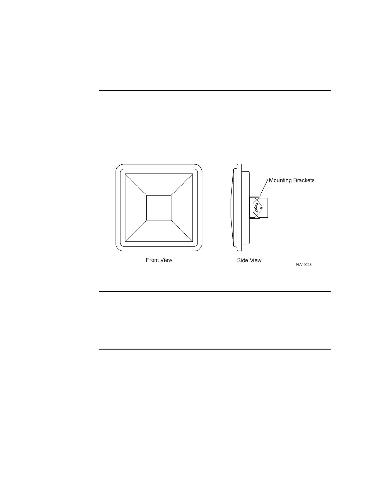
Figure 1-1 Encompass 4H Reader System Front and Side Views . . . . . . . . . . . . . . . . . . . . . 1-6
Figure 2-1 Tag and Reader Orientation . . . . . . . . . . . . . . . . . . . . . . . . . . . . . . . . . . . . . . . . . . 2-5
Figure 2-2 Encompass 4H Reader Location Relative to Tag Position . . . . . . . . . . . . . . . . . . . . 2-6
Figure 2-3 Typical Tag Positions for U.S. Driver’s Side Reader . . . . . . . . . . . . . . . . . . . . . . . .2-7
Figure 2-4 Typical Tag Positions for U.S. Passenger’s Side Reader . . . . . . . . . . . . . . . . . . . . .2-7
Figure 2-5 Typical Tag Positions Used with Overhead Reader . . . . . . . . . . . . . . . . . . . . . . . . .2-8
Figure 2-6 Gate Application with Center Island . . . . . . . . . . . . . . . . . . . . . . . . . . . . . . . . . . . . 2-10
Figure 2-7 Parking Garage Application . . . . . . . . . . . . . . . . . . . . . . . . . . . . . . . . . . . . . . . . . . 2-11
Figure 2-8 Overhead Installation . . . . . . . . . . . . . . . . . . . . . . . . . . . . . . . . . . . . . . . . . . . . . . .2-12
Figure 3-1 eGo Plus Windshield Sticker Tag . . . . . . . . . . . . . . . . . . . . . . . . . . . . . . . . . . . . . . .3-5
Figure 3-2 eGo Plus Security Sticker Tag . . . . . . . . . . . . . . . . . . . . . . . . . . . . . . . . . . . . . . . . . 3-5
Figure 3-3 eGo Plus License Plate Tag . . . . . . . . . . . . . . . . . . . . . . . . . . . . . . . . . . . . . . . . . . .3-6
Figure 3-4 eGo Windshield Sticker Tag . . . . . . . . . . . . . . . . . . . . . . . . . . . . . . . . . . . . . . . . . . .3-7
Figure 3-5 eGo License Plate Tag . . . . . . . . . . . . . . . . . . . . . . . . . . . . . . . . . . . . . . . . . . . . . . .3-7
Figure 3-6 eGo Plus Sticker Tag Placement . . . . . . . . . . . . . . . . . . . . . . . . . . . . . . . . . . . . . . .3-8
Figure 3-7 eGo Plus Sticker Tag Placement . . . . . . . . . . . . . . . . . . . . . . . . . . . . . . . . . . . . . . . 3-9
Figure 3-8 eGo Plus Sticker Tag Placement in Large Truck . . . . . . . . . . . . . . . . . . . . . . . . . . .3-9
Figure 3-9 Applying eGo Plus Sticker Tag to Windshield . . . . . . . . . . . . . . . . . . . . . . . . . . . .3-10
Figure 3-10 Second Step of eGo Plus Sticker Tag Application . . . . . . . . . . . . . . . . . . . . . . . .3-10
Figure 3-11 Applying eGo Plus Security Sticker Tag to Windshield . . . . . . . . . . . . . . . . . . . .3-12
Figure 3-12 Second Step of eGo Plus Security Sticker Tag Application . . . . . . . . . . . . . . . . .3-12
Figure 3-13 Correct Mounting Location for LPT . . . . . . . . . . . . . . . . . . . . . . . . . . . . . . . . . . . .3-14
Figure 3-14 Correct Tag Orientation . . . . . . . . . . . . . . . . . . . . . . . . . . . . . . . . . . . . . . . . . . . .3-14
Figure 3-15 Upper Placement Over the Top Area of the License Plate . . . . . . . . . . . . . . . . . .3-15
Figure 3-16 eGo Windshield Sticker Tag Placement Option A . . . . . . . . . . . . . . . . . . . . . . . . 3-16
Figure 3-17 eGo Windshield Sticker Tag Placement Option B . . . . . . . . . . . . . . . . . . . . . . . . 3-17
Figure 3-18 eGo Windshield Sticker Tag Placement Option C . . . . . . . . . . . . . . . . . . . . . . . . 3-17
Figure 3-19 Driver’s or Passenger’s Side (U.S.) Interior Windshield Tag Location . . . . . . . . .3-19
Figure 3-20 Upper Center Interior Windshield Tag Location . . . . . . . . . . . . . . . . . . . . . . . . . . 3-20
Figure 3-21 Hook-and-Loop Material on Interior Tag . . . . . . . . . . . . . . . . . . . . . . . . . . . . . . . .3-20
Figure 3-22 Proper Tag Orientation . . . . . . . . . . . . . . . . . . . . . . . . . . . . . . . . . . . . . . . . . . . . . 3-22
Figure 3-23 Correct Exterior Tag Placement . . . . . . . . . . . . . . . . . . . . . . . . . . . . . . . . . . . . . .3-23
Figure 3-24 Upper Placement In License Plate Area . . . . . . . . . . . . . . . . . . . . . . . . . . . . . . . . 3-24
Figure 3-25 Obstruction-Free Area . . . . . . . . . . . . . . . . . . . . . . . . . . . . . . . . . . . . . . . . . . . . . 3-24
Figure 3-26 Spacer Positioned Behind Tag . . . . . . . . . . . . . . . . . . . . . . . . . . . . . . . . . . . . . . . 3-25
Figure 3-27 Exterior Tag with Double-Sided Tape . . . . . . . . . . . . . . . . . . . . . . . . . . . . . . . . . .3-26
Figure 4-1 Wiring for Audible Circuit Tester . . . . . . . . . . . . . . . . . . . . . . . . . . . . . . . . . . . . . . . 4-5
Figure 4-2 Pin Assignments for Signal to Host Connectors . . . . . . . . . . . . . . . . . . . . . . . . . . . . 4-8
Figure 4-3 Back of the Encompass 4H Reader (reader shown has integrated antenna) . . . . .4-13
Figure 4-4 Factory-Mounted Bracket . . . . . . . . . . . . . . . . . . . . . . . . . . . . . . . . . . . . . . . . . . . .4-13
Figure 4-5 Pole-Mount Bracket Assembly . . . . . . . . . . . . . . . . . . . . . . . . . . . . . . . . . . . . . . . . 4-13
Figure 4-6 The Encompass 4H Reader Attached to the Pole Mount Bracket . . . . . . . . . . . . . 4-14
Figure 4-7 Front and Top Views of the Encompass 4H Reader Position . . . . . . . . . . . . . . . . .4-15
Figure 4-8 Wall Mount Bracket Accessory (part number 54-1620-001) . . . . . . . . . . . . . . . . . .4-16
Figure 4-9 Wall Mount Bracket Attached to the Encompass 4H Reader . . . . . . . . . . . . . . . . . 4-17
Figure 4-10 Factory-Mounted Bracket Attached to Wall Mount Bracket . . . . . . . . . . . . . . . . . 4-18
Figure 4-11 Pole Mount Bracket Attached to Wall . . . . . . . . . . . . . . . . . . . . . . . . . . . . . . . . . . 4-18
Encompass 4H Reader System Guide
xix
Page 20

Encompass 4H Reader System Guide
Figure 4-12 Connecting the Encompass 4H Assembly to Pole Mount Bracket . . . . . . . . . . . .4-19
Figure 4-13 Recommended Reader Cable Grounding . . . . . . . . . . . . . . . . . . . . . . . . . . . . . . .4-20
Figure 4-14 RS-232 Cable Extension Diagram . . . . . . . . . . . . . . . . . . . . . . . . . . . . . . . . . . . .4-23
Figure 4-15 Wiegand Cable Extension Diagram . . . . . . . . . . . . . . . . . . . . . . . . . . . . . . . . . . .4-25
Figure 4-16 Sample Circuit Connections . . . . . . . . . . . . . . . . . . . . . . . . . . . . . . . . . . . . . . . . .4-26
Figure 4-17 Sample Circuit Connections for IAG Installations . . . . . . . . . . . . . . . . . . . . . . . . .4-26
Figure 4-18 Sample Read Zone Marking Pattern . . . . . . . . . . . . . . . . . . . . . . . . . . . . . . . . . . .4-32
Figure 7-1 Example of Synchronization Bus Wiring . . . . . . . . . . . . . . . . . . . . . . . . . . . . . . . . .7-36
Figure 8-1 Connection Description Dialog Box . . . . . . . . . . . . . . . . . . . . . . . . . . . . . . . . . . . . . 8-6
Figure 8-2 Phone Number Dialog Box . . . . . . . . . . . . . . . . . . . . . . . . . . . . . . . . . . . . . . . . . . . .8-7
Figure 8-3 COM 1 Properties Dialog Box . . . . . . . . . . . . . . . . . . . . . . . . . . . . . . . . . . . . . . . . . .8-7
Figure 8-4 Hyper Terminal Main Screen . . . . . . . . . . . . . . . . . . . . . . . . . . . . . . . . . . . . . . . . . .8-8
Figure 8-5 Sign-on Message . . . . . . . . . . . . . . . . . . . . . . . . . . . . . . . . . . . . . . . . . . . . . . . . . . .8-9
Figure 8-6 Successful Tag Read . . . . . . . . . . . . . . . . . . . . . . . . . . . . . . . . . . . . . . . . . . . . . . .8-11
Figure 8-7 Second Successful Tag Read . . . . . . . . . . . . . . . . . . . . . . . . . . . . . . . . . . . . . . . .8-12
Figure 8-8 Encompass 4H Reader RF Control Options . . . . . . . . . . . . . . . . . . . . . . . . . . . . . .8-15
Figure C-1 DB9 and DB25 Connector Pin Assignments for Signal to Host. . . . . . . . . . . . . . . . C-4
xx
Page 21

List of Tables
Table 1-1 Typographical Conventions . . . . . . . . . . . . . . . . . . . . . . . . . . . . . . . . . . . . . . . . . . . . 1-5
Table 2-1 Connector Cabling Accessory Kits . . . . . . . . . . . . . . . . . . . . . . . . . . . . . . . . . . . . . . 2-13
Table 2-2 Power Supply Requirements . . . . . . . . . . . . . . . . . . . . . . . . . . . . . . . . . . . . . . . . . .2-14
Table 2-3 Recommended Cable Length from Transformer to the Encompass 4H Reader . . .2-15
Table 2-4 Communications Interfaces an d Co nd uc to r Re quirements . . . . . . . . . . . . . . . . . . .2-15
Table 3-1 Tags Read by the Encompass 4H Reader . . . . . . . . . . . . . . . . . . . . . . . . . . . . . . . . 3-3
Table 3-2 eGo Plus Tag Features . . . . . . . . . . . . . . . . . . . . . . . . . . . . . . . . . . . . . . . . . . . . . . .3-4
Table 3-3 eGo Tag Features . . . . . . . . . . . . . . . . . . . . . . . . . . . . . . . . . . . . . . . . . . . . . . . . . . . 3-6
Table 4-1 Installation Accessories . . . . . . . . . . . . . . . . . . . . . . . . . . . . . . . . . . . . . . . . . . . . . . .4-4
Table 4-2 AC Transformer Connections for Colored-Wire Pair Cable . . . . . . . . . . . . . . . . . . . . 4-6
Table 4-3 Low Voltage DC Cable Connections for the Colored-Wire Pair Cable . . . . . . . . . . .4-6
Table 4-4 RS–232 Interface Signal Wiring for Colored-Wire Pair Cable . . . . . . . . . . . . . . . . . .4-9
Table 4-5 Commands for Bench Testing . . . . . . . . . . . . . . . . . . . . . . . . . . . . . . . . . . . . . . . . .4-11
Table 4-6 RS–232 Interface Signal Wiring for Colored-Wire Pair Cable . . . . . . . . . . . . . . . . .4-22
Table 4-7 RS–422 Interface Signal Wiring for Colored-Wire Pair Cable . . . . . . . . . . . . . . . . .4-23
Table 4-8 Wiegand Interface Signal Wiring for Colored-Wire Pair Cable . . . . . . . . . . . . . . . . 4-24
Table 4-9 Sense Input/Output Cabling Assignments . . . . . . . . . . . . . . . . . . . . . . . . . . . . . . . . 4-28
Table 5-1 Four-Character Command Structure . . . . . . . . . . . . . . . . . . . . . . . . . . . . . . . . . . . .5-3
Table 5-2 Sample Command Sequence . . . . . . . . . . . . . . . . . . . . . . . . . . . . . . . . . . . . . . . . . .5-4
Table 7-1 Select Baud Rate Commands . . . . . . . . . . . . . . . . . . . . . . . . . . . . . . . . . . . . . . . . . . 7-6
Table 7-2 Select Stop Bits Commands . . . . . . . . . . . . . . . . . . . . . . . . . . . . . . . . . . . . . . . . . . .7-6
Table 7-3 Select Parity Commands . . . . . . . . . . . . . . . . . . . . . . . . . . . . . . . . . . . . . . . . . . . . . .7-7
Table 7-4 Append Time and Date Commands . . . . . . . . . . . . . . . . . . . . . . . . . . . . . . . . . . . . . .7-9
Table 7-5 Append Auxiliary Information Commands . . . . . . . . . . . . . . . . . . . . . . . . . . . . . . . . .7-9
Table 7-6 Unique ID Code Criteria . . . . . . . . . . . . . . . . . . . . . . . . . . . . . . . . . . . . . . . . . . . . . . 7-11
Table 7-7 Select Valid Code Commands and Frames . . . . . . . . . . . . . . . . . . . . . . . . . . . . . . .7-12
Table 7-8 Open/Closed Conditions for Output Status . . . . . . . . . . . . . . . . . . . . . . . . . . . . . . .7-22
Table 7-9 Open/Closed Conditions for Output Status (IAG Applications) . . . . . . . . . . . . . . . .7-23
Table 7-10 Open/Closed Conditions for Input Status . . . . . . . . . . . . . . . . . . . . . . . . . . . . . . . .7-23
Table 7-11 Flow Control Commands . . . . . . . . . . . . . . . . . . . . . . . . . . . . . . . . . . . . . . . . . . . . 7-31
Table 7-12 Output Control Commands . . . . . . . . . . . . . . . . . . . . . . . . . . . . . . . . . . . . . . . . . .7-32
Table 7-13 RF Control Commands . . . . . . . . . . . . . . . . . . . . . . . . . . . . . . . . . . . . . . . . . . . . .7-33
Table 7-14 RF Attenuation Command Variables . . . . . . . . . . . . . . . . . . . . . . . . . . . . . . . . . . . 7-34
Table 7-15 Example of Encompass 4H Reader Plaza Synchronization Bus Settings . . . . . . .7-37
Table 7-16 Output Pulse Duration Commands . . . . . . . . . . . . . . . . . . . . . . . . . . . . . . . . . . . .7-38
Table 7-17 Presence Without Tag Report Commands . . . . . . . . . . . . . . . . . . . . . . . . . . . . . . 7-39
Table 7-18 RF Control Algorithm Commands . . . . . . . . . . . . . . . . . . . . . . . . . . . . . . . . . . . . .7-39
Table 7-19 Timeout Period Values . . . . . . . . . . . . . . . . . . . . . . . . . . . . . . . . . . . . . . . . . . . . . . 7-40
Table 7-20 Input Inversion Options . . . . . . . . . . . . . . . . . . . . . . . . . . . . . . . . . . . . . . . . . . . . . 7-41
Table 7-21 Input Status Change Report Options . . . . . . . . . . . . . . . . . . . . . . . . . . . . . . . . . . . 7-43
Table 8-1 Encompass 4H Reader Configuration Label Fields . . . . . . . . . . . . . . . . . . . . . . . . . 8-3
Table 8-2 Encompass 4H Reader Default Configuration Settings . . . . . . . . . . . . . . . . . . . . . . 8-4
Table 8-3 Command Sequence to Verify Communications . . . . . . . . . . . . . . . . . . . . . . . . . . 8-10
Table 9-1 Error Messages . . . . . . . . . . . . . . . . . . . . . . . . . . . . . . . . . . . . . . . . . . . . . . . . . . . . . 9-3
Table 9-2 Symptoms and Remedies . . . . . . . . . . . . . . . . . . . . . . . . . . . . . . . . . . . . . . . . . . . . . 9-4
Table C-1 Communications Interfaces and Conductor Requirements. . . . . . . . . . . . . . . . . . . . .C-3
Table C-2 RS–232 Interface Signal Wiring for Colored-Wire Pair Cable. . . . . . . . . . . . . . . . . . C-5
Contents
xxi
Page 22

Encompass 4 Reader System Guide
Table C-3 RS–232 Interface Signal Wiring for Alternate Wire Cable. . . . . . . . . . . . . . . . . . . . . C-5
Table C-4 RS–422 Interface Signal Wiring for Colored-Wire Pair Cable . . . . . . . . . . . . . . . . . . C-6
Table C-5 RS–422 Interface Signal Wiring for Alternate Wire Cable. . . . . . . . . . . . . . . . . . . . . C-6
Table C-6 Wiegand Interface Signal Wiring for Colored-Wire Pair Cable . . . . . . . . . . . . . . . . . C-7
Table C-7 Wiegand Interface Signal Wiring for Alte rn at e Wire Cable . . . . . . . . . . . . . . . . . . . . C-7
Table C-8 AC Transformer Connections for Colored-Wire Pair Cable. . . . . . . . . . . . . . . . . . . . C-7
Table C-9 AC Transformer Connections for Alternate Wire Cable. . . . . . . . . . . . . . . . . . . . . . . C-9
Table C-10 Low Voltage DC Cable Connections for Colored-Wire Pair Cable . . . . . . . . . . . . . C-9
Table C-11 Low Voltage DC Cable Connections for Alternate Wire Cable . . . . . . . . . . . . . . . . C-9
Table C-12 Sense Input/Output Cabling Assignments for Colored-Wire Pair Cable . . . . . . . . C-10
Table C-13 Sense Input/Output Cabling Assignments for Alternate Wire Cable . . . . . . . . . . . C-12
Table C-14 All Cabling Assignments for Colored-Wire Pair Cable or Alternate Wire Cable. . . C-14
Table D-1 Encompass 4H Reader Default Configuration Settings . . . . . . . . . . . . . . . . . . . . . . D-3
Table D-2 Encompass 4H Reader Commands Listed Numerically . . . . . . . . . . . . . . . . . . . . . . D-5
Table D-3 Encompass 4H Reader Commands Listed Alphabetically . . . . . . . . . . . . . . . . . . . D-17
Table E-1 SeGo Protocol Tags. . . . . . . . . . . . . . . . . . . . . . . . . . . . . . . . . . . . . . . . . . . . . . . . . . E-3
Table E-2 eGo Protocol Tags. . . . . . . . . . . . . . . . . . . . . . . . . . . . . . . . . . . . . . . . . . . . . . . . . . . E-4
Table E-3 ATA Protocol Tags. . . . . . . . . . . . . . . . . . . . . . . . . . . . . . . . . . . . . . . . . . . . . . . . . . . E-4
xxii
Page 23

1
Introduction
Page 24

Page 25

Purpose
Introduction
Chapter 1
Introduction
This chapter is the introduction to this manual and provides information
pertaining to the audience, organization, document conventions, system
®
description, and license information for the Encompass
System.
This guide provides site planning and testing, installing, and operating instructions for
TransCore’s Encompass 4H Reader System, a dual-protocol reader that reads
®
TransCore Super eGo
tions (ATA)/International Organization for Standardization (ISO), and Inter-Agency
Group (IAG) tag protocols. Before you begin installing the Encompass 4H Reader
System, TransCore recommends that you read this entire manual.
(SeGo), Intellitag®-based eGo, American Trucking Associa-
4H Reader
Audience
This document is intended to be used by authorized T ransCore Encompass 4H Reader
System dealers, installers, and service personnel. Because the Encompass 4H Reader
System has no operator- or end-user serviceable components or features, no end-user
manual or operator guide exists. Once the system is set up and tested by the
authorized
intervention.
installer, Encompass 4H Reader System operation requires no end-user
System Guide Organization
The chapters of this guide and a description of the contents are listed here.
• Chapter 1, “Introduction,” explains the purpose and describes the audience for the
guide, outlines the manual’s organization, provides a brief description of the
Encompass 4H Reader system, and discusses Federal Communications Commis
sion (FCC) licensing requirements.
• Chapter 2, “Developing the Site Plan,” discusses factors to be considered when
developing the site plan and before ordering equipment and installing the Encom
pass 4H Reader System. These considerations include reader and tag alignment,
site layout and traffic flow, and electrical and communications requirements.
-
-
• Chapter 3, “Choosing, Installing, and Removing Tags,” contains information on
1-3
Page 26

Encompass 4H Reader System Guide
compatible tag models and provides procedures for installing tags onto, and
removing tags from, vehicles that use the facility where the Encompass 4H
Reader System is installed.
• Chapter 4, “Installing the Encompass 4H Reader System,” lists the materials
needed and provides procedures to install the Encompass 4H Reader System.
Steps include:
• Pre-testing
• Installing the Encompass 4H Reader System on a round pole or flat surface
• Connecting power and communications
• Marking the read zone.
• Chapter 5, “General Software Information,” and Chapter 6, “Communications
Protocols,” provide reference information on various software-related topics and
communications protocols.
• Chapter 7, “Commands,” discusses the host-transmitted commands that are used
to control Encompass 4H Reader System configuration and operation.
• Chapter 8, “Configuring the Encompass 4H Reader System,” provides procedures
for configuring and fine-tuning the Encompass 4H Reader System after installing
it at the site.
• Chapter 9, “Troubleshooting and Maintenance,” answers the most commonly
asked questions about installing and maintaining the Encompass 4H Reader Sys
tem.
-
• Appendix A, “Glossary,” contains frequently used terms.
• Appendix B, “T echnical Specifications,” provides the Encompass 4H Reader Sys-
tem specifications.
• Appendix C, “Wiring Tables,” shows the wiring connections for the communica-
tions interfaces, electrical cable connections, and the external interface signal wiring.
• Appendix D, “Command Quick Reference,” lists the Encompass 4H Reader Sys-
tem factory default configuration settings and provides host software commands
in numerical and alphabetical order.
• Appendix E, “Compatible Tag Information,” provides helpful information about
tags that are compatible with the Encompass 4H Reader System.
• Index provides an alphabetical listing of guide topics.
1-4
Page 27

Typographical Conventions
The conventions listed in Table 1-1 are used in this manual:
Table 1-1 Typographical Conventions
Convention Indication
Concerns about a procedure.
Introduction
Code
Dialog Box Title
Menu Item
Note
NUL Zero-value ASCII character or a zero-value byte.
NULL Zero-value pointers. Null-terminated string refers to strings
System Description
Code, including keywords and variables within text and as
separate paragraphs, and user-defined program elements
within text appear in courier typeface.
Title of a dialog box as it appears on screen.
Appears on a menu. Capitalization follows the interface.
Auxiliary information that further clarifies the current
discussion. These important points require the user’s
attention. The paragraph is in italics and the word Note is
bold.
of pr
intable ASCII characters with a zero-value byte placed
in memory directly after the last printable charac te r of th e
string.
This procedure might cause harm to the equipment and/or
the user.
The Encompass 4H Reader System is a dual-protocol reader supporting the low-cost,
high-performance SeGo radio frequency identification (RFID) technology . SeGo tech nology provides the capability to r
ead miniature RFID tags in a myriad of options
including rugged, durable, or thin flexible forms such as the eGo Plus Sticker Tag. The
Encompass 4H Reader System also supports legacy transportation applications such
as gated toll, parking, or security gate access and is designed to be compatible with
®
existing TransCore SmartPass
parking access control applications. The Encompass
1-5
Page 28
Encompass 4H Reader System Guide
4H Reader System also supports the TransCore eGo and T ransCore full frame and half
ATA/ISO tag types, as well as the IAG tag protocol.
frame
Reader
The Encompass 4H Reader System consists of an input/output (I/O) module, a power
supply, a reader logic board (also called a tag decoder), a radio frequency (RF) transmitter/receiver (called the RF module), and a patch
antenna.
These Encompass 4H Reader System components
compact, and easy-to-install environmentally-sealed package. Figure 1-1 shows the
front and side views of an Encompass
Figure 1-1 Encompass 4H Reader System Front and Side Views
4H Reader System.
are contained in a highly reliable,
Tags
The Encompass 4H Reader System has the capability to read TransCore SeGo protocol tags, the Intellitag-based eGo protocol
TransCore ISO-compliant read-only full- and half-frame tags, as well as IAG protocol
tags.
tags, TransCore ATA protocol, and
1-6
How It Works
The Encompass 4H Reader System directs the RF module to generate an RF signal,
which is broadcast through the integrated antenna. Entering the Encompass 4H Reader
System’s reading range, a T ransCore RFID tag installed on a vehicle or other object to
be tracked adds its programmed identification information to the signal and reflects
the signal back to the Encompass 4H Reader System. The Encompass 4H Reader System receives this modified, or modulated signal, and decodes the tag data carried by
reflected signal and transmits this data to a local host computer for processing.
the
Page 29

T echnical Support
Authorized dealers and distributors are responsible for the direct support of all
customers. Authorized dealers and distributors needing technical support can contact:
Technical Support
Phone: (505) 856-8007
Web: transcore.com/rfidsupport
Please be prepared to answer a series of questions that are designed to direct you to the
best support resource available.
Introduction
1-7
Page 30

Encompass 4H Reader System Guide
1-8
Page 31

2
Developing the Site Plan
Page 32

Page 33

Overview
Developing the Site Plan
Chapter 2
Developing the Site Plan
This chapter discusses site plan development for installing the
®
Encompass
Developing a site plan provides the foundation for the site’s system design and establishes the number and general location of
Also, consider the following factors when developing a site plan:
• Type of tags used in the facility
• Reader and tag alignment
4H Reader System.
primary components.
• Site layout and traffic flow
• Encompass 4H Reader mounting requirements
• Encompass 4H Reader electrical requirements
• Encompass 4H Reader communications requirements
These factors provide relevant information regardin
magnetic environment and the conditions under which the
Reading of Mixed Population T ags
The Encompass 4H Reader reads TransCore’s Super eGo® (SeGo) protocol tags, the
American Trucking Association (ATA) and International Organization for Standardization (ISO) read-only tags, whether powered by batte
cific integrated circuit (ASIC)-based tags with Intellitag technology
Group (IAG) tags. The reader can read the ATA or ISO rea d-only ta gs in the presence
of Intellitag-based tags; however, attempting to read an Intellitag-based tag in the
presence of an ATA or ISO read-only tag is not recommended.
Caution
Attempting to read an Intellitag-based tag in the presence of an ATA or ISO read-only
tag may
The factors that influence the readability include, but are not limited t
tation and configuration, type of read-only tag, ratio of
tags, and whether the tag is battery- or beam-powered.
provide unreliable results.
g each site’s physical and electro-
system must perform.
ry or beam, application-spe-
, or Inter-Agency
o physical orien-
backscatter cross-section of the
2-3
Page 34

Encompass 4H Reader System Guide
Reader and Tag Alignment
The position of the Encompass 4H Reader and placement of the tag on the vehicle
must be compatible. Also, consider any existing tagged vehicl es now using the facility
to determine the optimal Encompass 4H Reader location and orientation at the site.
Note: If any of
in toll applications, contact TransCore for information about mixed-tag installations
before you plan tag type, location, and programming.
Three primary criteria must be satisfied to
the vehicles using your facility already have tags, such as those used
achieve the highest read reliability:
• Polarization of the tag and the Encompass 4H Reader must be aligned in the same
direction
— both horizontal.
• The installed tag must be in a direct, unobstructed line of sight to the Encompass
4H Reader.
• T ags desig ned to be moun ted in a vehicle wind shield must be moun ted in the vehi -
cle’s windshield, and tags designed to be mounted on the exterior surface of the
ve
hicle must be mounted on the exterior surface of the vehicle.
Caution
A tag may not be reliably read unless the preceding criteria are met.
2-4
Page 35

Developing the Site Plan
Polarization
The polarization of the tag must be aligned in the same direction as the Encompass
4H Reader, as shown in Figure 2-1.
Note: Matching the
performance
.
tag and reader polarization is critical to obtain optimal system
Figure 2-1 Tag and Reader Orientation
2-5
Page 36

Encompass 4H Reader System Guide
Unobstructed Line of Sight
For optimum readability, install the Encompass 4H Reader and the vehicle’s tag so
that when the vehicle approaches the Encompass 4H Reader, the tag is directly facing
the reader and the line of sight is clear between the Encompass 4H Reader and the tag.
If a fence or barrier is between the tag and the reader, the Encompass 4H Reader cannot reliably read the tags. Figure 2-2 illustrates possible installation locations of an
Encompass 4H Reader in relation to a tag’
are not in the recommended location, reliable optimum operation requires lower vehicle speeds.
s mounting location on a vehicle. If the tags
2-6
Figure 2-2 Encompass 4H Reader Location Relative to Tag Position
Page 37

Developing the Site Plan
If the Encompass 4H Reader is installed on a pole or wall to the
left of the vehicle,
optimal tag position is on the left side of the vehicle as illustrated in Figure 2-3.
Figure 2-3 Typical Tag Positions for U.S. Driver’s Side Reader
If an Encompass 4H Reader is installed on a pole or wall to the right of the vehicle,
optimal tag position is on the right side of the vehicle as illustrated in Figure 2-4.
Figure 2-4 Typical Tag Positions for U.S. Passenger’s Side Reader
2-7
Page 38

Encompass 4H Reader System Guide
If the Encompass 4H Reader is installed in an overhead
is in the top center of the windshield in the area behind the rear view mirror or on the
vehicle’s front license plate or center bumper as illustrated in Figure 2-5.
Figure 2-5 Typical Tag Positions Used with Overhead Reader
location, optimal tag position
Note: Metallized coatings on some vehicle windshields and windows shield the RF
energy emitted by the Encompass 4H Reader and may cause tags to be misr ead. Many
metallized windshields have areas that are not metallized in which the tag can be
placed and reasonable results achieved. If there are no openings in the metallized
coating in which to install an interior tag, install exterior-type tags on the exterior of
the vehicle.
Refer to Chapter Chapter 3, ”Choosing, Install
detailed information on
tag positioning.
Site Layout and Traffic Flow
The following site layout and traffic flow considerations are critical when determining
Encompass 4H Reader installation locations:
• The Encompass 4H Reader read zone
• Other Encompass 4H Reader units in the area
• Lane configurations
• Reflection, refraction, and diffraction of RF signals
• Existing signal interference at the site
ing, and Removing Tags” for more
2-8
Page 39

Developing the Site Plan
The Encompass 4H Reader Read Zone
The Encompass 4H Reader must be able to read the tag data properly within a specified area, called the read zone, without reading other nearby tags or interfering with
other Encompass 4H Readers at the site. The following are some of the factors that
affect the size and shape of the read zone:
• Mounting method used (pole or wall mount)
• Mounting location (overhead or side mount)
• Height from the ground and mounting angle
• Indoor or outdoor location
• RF output attenuation
• Range discrimination setting
• Other sources of interference and reflection
The Encompass 4H Reader must be positioned to allow the RF signal to travel to and
return from the tags within the designated range and be placed in an area where it is
not likely to be bumped out of alignment. If the reader becomes misaligned or some
nearby structure is added or removed, system operation can be seriously affected.
For instructions on setting the read zone, see “Fine-Tuning and Verifying the Read
Zone” on page 8-19.
Other Encompass 4 Readers in the Area
Encompass 4 Readers may not operate accurately if they directly face each other or
are positioned back-to-back.
Lane Configurations
TransCore recommends that traffic be guided through a controlled lane to consistently
obtain accurate tag readings and to prevent physical damage to the Encompass 4H
Reader. The following subsections describe some common lane configurations and
offer suggestions for positioning the Encompass 4H Reader within the controlled traf
fic flow.
Note: Regulatory requirements restrict the amount of RF power to 4 Watts EIRP that
can be transmitted from the Encompass 4H reader. In a side fire mounted application,
this reduction in RF power has been shown to impact the available read zone size and
speed at which the tagged vehicles can pass by the reader an d b e reliably read for all
tags except ATA battery tags. If any other tag type is being used, the end user needs
to be aware of the reduction in performance and should perform testing in their antic
ipated application to confirm it will meet their system requirements.
-
-
2-9
Page 40

Encompass 4H Reader System Guide
Gate with Center Island Configuration
Figure 2-6 illustrates a typical gate application with the Encompass 4H Reader units
positioned on a center island to read tags mounted on
driver’s side (United States). The readers are placed to allow time for the gate to open
so the vehicle can roll through without stopping while not allowing room for an
untagged vehicle to be between the vehicle being read and the gate.
the inside windshield on the
2-10
Figure 2-6 Gate Application with Center Island
Page 41

Developing the Site Plan
Parking Garage with Ticket Island Configuration
Figure 2-7 illustrates a parking garage application with each Encompass 4H Reader
mounted on the ticket island to read tags mounted
on the center front vehicle bumper. The Encompass 4H Reader placement may require
the vehicle to stop before the gate opens.
on the inside center windshield or
Figure 2-7 Parking Garage Application
Overhead Reader Installation Configuration
Another option for Encompass 4H Reader placement is to mount it overhead in each
lane as illustrated in Figure 2-8. This illustration assumes that tags are mounted on the
inside center windshield or center bumper of the vehicle.
2-11
Page 42

Encompass 4H Reader System Guide
Figure 2-8 Overhead Installation
Lane Configurations for Encompass 4H Readers
TransCore recommends that traffic be guided through a controlled lane to consistently
obtain accurate tag readings and to prevent physical damage to the Encompass 4H
Reader.
Reflection, Refraction, and Diffraction of RF Signals
RF signals can be reflected, refracted, or diffracted by metal objects, walls, and even
wet pavement or ice. Any of these factors can alter or degrade system performance.
When designing your site plan, you must consider permanent structures and transient
factors in the vicinity that may affect RF signals being generated by the Encompass
4H Reader. Permanent structures include buildings, chain link fences, guard shacks,
and gates. Transient factors include passing traffic and local weather conditions, such
as rain or snow. Symptoms of reflection, refraction, and diffraction include reading
tags that are out of the desired read zone or tags being read from another lane.
The most common RF reflectors are
tially reflected by nonconducting materials suc
crete. When nonconducting materials in the system
increase reflection of RF signals.
The Encompass 4H Reader mounting location, aiming, and range
and use of presence detectors can reduce interference from RF reflections. When these
actions cannot adequately control reflections, other techniques such as shielding,
absorbing, range sensitivity adjustment, or barriers can also be used. See Chapter 9,
”Troubleshooting and Maintenance” for more information.
metallic surfaces. RF signals may also be par-
h as dirt, wood, ice, asphalt, and con-
environment become wet, they
control adjustment,
2-12
Page 43

Developing the Site Plan
Existing Interference
Interference from RF and electrical sources can degrade system performance and must
also be considered in the site design. Fluorescent lights, neon signs, nearby radio sta
tions, or power lines can interfere with the optimal operation of the system. The mag netic impulse noise from relays that control gate opening and closing can also disrupt
the RF signal.
Interference may degrade both reader and tag performance. Existing interference at
the site may be shielded, removed, or positioned further from the Encompass 4H
Reader.
receiving the reader interrogation (see
Strong RF sources of any frequency , in proximity to the tag, can preclude the tag
Chapter 9, ”Troubleshooting and Maintenance” ).
Electrical and Communications Requirements
All construction work at the site must be completed before installing the Encompass
4H Reader. Electrical and communications cables should be installed according to all
applicable local and federal building code requirements. Specific instructions for posi
tioning and installing the Encompass 4H Reader are discussed in Chapter 4, ”Install-
ing the Encom pass 4H Reader”.
-
-
Junction Box
Use a watertight junction box that meets applicable local and national building codes
for connecting power and communications wiring. The junction box houses the termi
nal strip for power and communications connections. TransCore recommends a
NEMA Type-4 junction box with a back mounting panel.
Power and Communications Cables
Cable length for power and communications depends on the physical characteristics
of the Encompass 4H Reader installation site.
for cabling options based on your site’s requirements.
Table 2-1 Connector Cabling Accessory Kits
Part Number Description
58-1620-001 5-ft connector cable harness
58-1620-002 20-ft connector cable harness
58-1620-006 35-ft connector cable harness
58-1620-007 45-ft connector cable harness
Table 2-1 lists accessory kits available
-
20-1620-003 Connector kit only
56-1620-004 13-pair cable (sold by the foot)
2-13
Page 44

Encompass 4H Reader System Guide
Table 2-1 Connector Cabling Accessory Kits (continued)
Part Num
76-1620-005 110V AC to 18V AC Class C transformer
76-1620-006 12V AC to 18V AC step-up transformer
76-1620-008 220V AC to 18V AC Class C Transformer
ber Description
Electrical Power
A dedicated electrical power supply must be present at the site and available to the
Encompass 4H Reader at all times. The power must be 16-20V AC or 16-28V DC. A
step-down transformer is available (North America only) to convert a 120V AC
duplex wall outlet with ground to 18V AC, as is a step-up transformer to convert a
low-voltage 12V AC outlet to 18V AC. Consult your local and national electrical
codes for installation and safety requirements.
Note: Encompass 4H Reader
plied transformer.
Note: For IEC6
0950 compliance, this unit must be used in conjunction with a certified limited power source (LPS). The LPS should be rated for
age, 3Amps maximum output current or 16-28VD
and limited to less than 100VA apparent power.
s installed outside North America require a locally sup-
16-20VAC output volt-
C 3Amps maximum output current,
If 18V AC or 18V DC power is available, the transformer option is unneces
TransCore offers a Class C transformer acces
sory kit (part number 76-1620-005) for
sary.
sites where 110V AC is available. For sites with 220V AC, an accessory kit (part number 76-1620-008) is also available. It is the i
nstaller’s responsibility to supply conversion equipment and wiring for other voltages. T able 2-2 contains p ower supply current
requirements.
Table 2-2 Power Supply Requirements
(RF On)
Supply
16 to 20V AC 20 watts (W) 14 W
16 to 28V DC 20 W 14 W
a
1700 milliamp (mA) initial rush-in current at startup
Maximum Power at
68°F (20°C)
a
(RF Off)
Standby Operating
Power at 68°F (20°C)
a
Power circuits are protected internally against power surges.
Power Extension
2-14
Page 45

Developing the Site Plan
Use Table 2-3 to determine the correct cable size acc
Gauge (AWG) standard for the necessary length of
ording to the American Wire
extension cable. The numbers in
the first row of the table indicate cable size for the approximate cable length .
Note: If
the cable is close to the maximu m len gth, measure voltage at the Encompass
4H Reader with RF ON to ensure voltage does not drop below 16V. A drop in voltage
below 16V causes a reduction in read range and possible damage to internal electronics as well as unreliable operation.
Table 2-3 Recommended Cable Length from Transformer to the Encompass 4H Reader
Cable Size (AWG)
Maximum DCR (Ohms
pe
r foot at 68
TransCore 5-ft cable
(P/N 58-1620-001)
TransCore 20-ft cable
(P/N 58-1620-002)
TransCore 35-ft cable
(P/N 58-1620-006)
°F)
a
b
c
c
c
24 22 20 18 16 14 12
0.0270 0.0175 0.0109 0.0069 0.0044 0.0027 0.0017
23 ft 36 ft 58 ft 92 ft 144 ft 235 ft 373 ft
15 ft 23 ft 38 ft 60 ft 93 ft 152 ft 242 ft
7 ft 11 ft 17 ft 27 ft 43 ft 70 ft 110 ft
TransCore 45-ft cable
(P/N 58-1620-007)
a. Use two pair (two conductors for power and two for return). TransCore cable is 22 AWG.
b. Direct current resistance (DCR) information is from the Belden catalog.
c. Based on a 1.0V drop at 1200 mA (RF ON) with 15% margin.
c
1 ft 2 ft 4 ft 6 ft 9 ft 14 ft 23 ft
Host Communications
Your site design must include communications between the Encompass 4H Reader
and a host computer. The Encompass 4H Reader communicates with the host computer through an asynchronous serial line or th
line can be an RS
–232 interface or an RS–422 interface. The host computer must be
able to accept one of the interfaces shown in Table 2-4.
Table 2-4 Communications Interfaces and Conductor Requirements
Interface
–232 3
RS
RS
–232 with RTS and CTS hardware and handshake
signals
rough a Wiegand interface. This serial
Number of
Co
nductors
5
RS
–422 4
2-15
Page 46

Encompass 4H Reader System Guide
Table 2-4 Communications Inte rfaces and Conductor Requirements
Interface
Wiegand 3
Number of
Conductors
2-16
Page 47

Developing the Site Plan
RS–232 Interface
Use an RS–232 interface if one or more of the following conditions apply to your site:
• The host computer system is 50 ft (15.2 m) or less from the Encompass 4H
Reader.
• The host computer system is more than 50 ft (15.2 m) from the Encompass 4H
Reader and a pair of RF modems or limited distance modem/l ine drivers over
copper wire are used for communications between the Encompass 4H Reader and
the host. The distance from the RF modem to the Encompass 4H Reader should
not exceed 50 ft (15.2 m).
• Other common communications devices that can extend the RS–232 distance,
such as fiber optic modems, have been selected.
The standard RS–232 connection maximum distance depends on the baud rate, cab le
type, and the RS
Note: When extending the RS-232 interface, use a three-pair cable such as Belden
2919. Use a twisted pair for the black (RxD) with ground (black of the black/yellow
pair), and a twisted pair for red (TxD) with ground (black of the black/yellow pair).
The third pair of the three-pair cable can be used for a spare in the event either of the
other two pair are damaged or fail. The cable shield should be tied to a single-point
earth ground on the controller end of the cable.
–232 device at the other end.
RS–422 Interface
Use an RS–422 interface if one or more of the following conditions apply to your site:
• The host computer is more than 50 ft (15.2 m) from the Encompass 4H Reader.
• The host computer has an external limited-distance modem.
The standard RS–422 connection maximum distance depends on the baud rate, cab le
type, and the RS
Wiegand Interface
The Encompass 4H Reader can interface with equipment requiring the Wiegand
DC data0-data1-ground interface. The reader uses the Wiegand interface
+5V
included with the RS
Note: The Encompass 4H Reader comes from the factory with either RS–232 and
Wi eg an d or RS
the Encompass 4H Reader using the RS
operating parameters in the reader, then set the Encompass 4H Reader’s configura
tion to Wiegand, and then connect the Encompass 4H Reader to the Wiegand inter-
face.
Note: Yo u must order tags programmed with Wiegand-formatted data when using a
Wiegand-compatible reader.
–422 device at the other end.
–232 or RS–422 option.
–422 and Wiegand. If you want to use Wiegand, you must first connect
–232 or RS–422 interface, set all necessary
-
2-17
Page 48

Encompass 4H Reader System Guide
Note: When extending the Wiegand interface, use a three-pair cable such as Belden
2919. Use a twisted pair for the red (Data1) with ground (yellow of the black/yellow
pair), and a twisted pair for blue (Data0) with ground (yellow of the black/yellow
pair). The third pair of the three-pair cabl e can be used for a spare in the event either
of the other two pair are damaged or fail. The cable shield should be tied to a singlepoint earth ground on the controller end of the cable.
Input/Output Circuits
To connect the Encompass 4H Reader to external equipment such as a treadle or traffic control light, install wires from these devices at the junction box. The Encompass
4H Reader input circuit is designed to connect to a dry contact closure. The Encom
pass 4H Reader output circuits are single-pole, double-throw relays providing dry
contact closures. These contacts are rated at 42.2V AC peak (30V
A maximum with noninductive load.
Output circuits are not intended for the direct control of electromechanical devices
such as motorized gates and barrier arms. For such applications, the Encompass 4H
Reader output circuits should be used to drive a secondary, appropriately rated
high-power relay.
) or 60V DC, at 1
rms
-
2-18
Page 49

3
Choosing, Installing, and Removing
Tags
Page 50

Page 51

Choosing, Installing, and Removing Tags
This chapter describes the various tag types compatible with the
Encompass
compatible internal and external tags.
Compatible Tag Types
The Encompass 4H Reader provides the capability to read the various TransCore
®
eGo
Plus-type tags employing Super eGo (SeGo) protocol and eGo-style tags and
other American National Standards Institute (ANSI) ANS INCITS 256-2001-compliant tags with Intellitag technology
Reader can read eGo Plus and eGo tags as well as TransCore IT2000 (in optional
ATA/ISO mode), AT A-protocol, ISO-compliant tags, and Inter-Agency (IAG) tags. It
can also read tags formatted to a wide range of industry-standard proprietary formats,
including SIA Wiegand 26-bit standard format.
®
4H Reader and the procedures for installing and removing
Choosing, Installing, and Removing Tags
Chapter 3
. Depending on options ordered, the Encompass 4H
See Appendix E for information about the n
Reader and Tag Model Interoperability
Table 3-1 lists the tags that are read by the Encompass 4H Reader. See
www.transcore.com/pdf/T
cerning readers and supported tag protocols.
Table 3-1 Tags Read by the Encompass 4H Reader
Reader Beam Tags Battery Tags
Encompass 4H Reader eGo Plus Sticker Tag*; eGo Plus
Security Sticker T
License Plate Tag*
eGo Windshield Sticker Tag;
eGo Ta
License Plate Tag
other ANS INCITS 256-2001compliant tags with Intell
technology
AT5100; AT5102; AT5110;
AT5
112; AT5125; AT5145;
AT5146; AT5715
ag-Reader-Matrix.pdf for most current information con-
ag*, eGo Plus
mper Resistant Tag; eGo
itag
umerous tag models.
AT5105; AT5114; AT5140;
47; AT5510; AT5540;
AT51
AT5541; AT5542; AT5543;
AT5544; AT5545; AT5547;
AT5704; AT5707; IT2221**;
IT2235**
* in SeGo, eGo, and/or ATA
mo
des
** When used in optional ATA/ISO
mode
3-3
Page 52

Encompass 4H Reader System Guide
TransCore’s eGo Plus Tags
TransCore’s eGo Plus tags are offered to complete your Encompass 4H Reader System. Table 3-2 lists some of the features of the TransCore eGo Plus tags.
Table 3-2
Sticker Tag
Security
Sticker T
License
Pla
(LPT)
#
the first "x" in the sticker tag listing defines which protocol is dominant (e.g., ATA or eGo/SeGo) in the tag;
the second "x" further defines other active protocol configurations; and "nnn" is a unique identifier that
differentiates between tags that are programmed similarly but that have different graphics or labels).
##
the "x" in the security sticker tag listing defines which protocol is dominant (e.g., ATA or eGo/SeGo) in the
tag; the "y" further defines other active protocol configurations; and "zzz" is a unique identifier that
differentiates between tags that are programmed similarly but that have different graphics or labels)
###
version.
eGo Plus Tag Features
Number
Tag
ag
te Tag
the "x" in the LPT listing determines whether the LPT is a standard eGo Plus LPT or a motorcycle
Part
Number
13-07xx-
#
n
nn
13-07xy-
##
zzz
13-0700-
###
90
x
Used For
Toll,
Electronic
vehicle
registration
(EVR),
Parking,
Security
access
Special
Fe
atures
Very thin,
flexible,
multi-lay
lamination
Very thin,
flexible,
multi-layer
lamination,
tamper
detection
Waterresistant,
exteriormounted
er
Power
Source
Beam
6-bit
of
ASCII
Characters
20 1 N/A
10 1/2 26 to 54
20 1 N/A
10 1/2 26 to 54
20 1 N/A
10 1/2 26 to 54
Number
of 128-
Bit
Frames
Wiegand
Number
of
Bits
3-4
eGo Plus Sticker Tag
The Encompass 4H Reader reads the eGo Plus Sticker Tag (Figure 3-1) configured to
support SeGo mode.
Page 53

Choosing, Installing, and Removing Tags
Figure 3-1 eGo Plus Windshield Sticker Tag
eGo Plus Security Sticker Tag
The Encompass 4H Reader reads the eGo Plus Security Sticker Tag (Figure 3-2) configured to support SeGo mode.
Figure 3-2 eGo Plus Security Sticker Tag
eGo Plus License Plate Tag
The eGo Plus LPT (Figure 3-3) is a water-resistant tag used in applications requiring
an exterior-mounted tag.
3-5
Page 54

Encompass 4H Reader System Guide
Figure 3-3 eGo Plus License Plate Tag
TransCore’s eGo Tags
TransCore’s various eGo tags are offered to complete your Encompass 4H Reader
System. Table 3-3 lists some of the features of the TransCore eGo tags.
Table 3-3
Tag
Windshield
Sticker T
License
Plate T
ag
eGo Tag Features
Part
Number
13-0510-
ag
004
13-0510900
eGo Windshield Sticker Tag
The TransCore eGo WST (Figure 3-4) is offered to complete your Encompass 4H
Reader System. It is a flexible sticker much
Used For
Toll,
Electronic
vehicle
registration
(EVR),
Parking,
Security
access
Special
Features
Very thin,
flexible,
multi-lay
lamination
Waterresistant,
exteriormounted
er
Power
Source
Beam
Number
of 6-bit
ASCII
Characters
20 1 NA
10 1/2 26 to 54
20 1 NA
10 1/2 26 to 54
Number
of 128-
Bit
Frames
like a vehicle registration sticker.
Number
of
Wiegand
Bits
3-6
Page 55

Figure 3-4 eGo Windshield Sticker Tag
Choosing, Installing, and Removing Tags
eGo License Plate Tag
The eGo LPT (Figure 3-5) is a water-resistant tag used in applications requiring an
exterior-mounted tag.
Figure 3-5 eGo License Plate Tag
Installing eGo Plus Sticker Tags
eGo Plus Sticker Tags are designed to be attached by a semi-permanent adhesive to
the interior surface of nonmetallic windshields 0.190 to 0.230 inches (4.82 to 5.84
mm) in thickness. For optimum performance, you must install the tag at least 2 inches
(5 cm) from the metal in the windshie
view mirror support post. Detailed instructions for installing t
Tag are found in the pocket guide “Quick and Easy Installation Instructions for the
®
Plus Sticker Tag.”
eGo
ld frame and 0.75 inch (1.9 cm) from the rear-
he eGo
®
Plus Sticker
Some vehicles have a tinted area across the top of the windshield. If t
tive, it can interfere with reading the
tag must be installed at least 2 inches (5 cm) below this tinted area.
tag. If a windshield has this conductive tint, the
he tint is conduc-
3-7
Page 56

Encompass 4H Reader System Guide
Some vehicle windshields contain a metallic treatment that could
windshield-mounted tag from being read. However, many of these metallized windshields have areas that are not
allized windshield, you might need to install an Encompass
LPT on the vehicle. See the section “Installing eGo Plus License Plate Tags” on page
3-13. Contact TransCore for more information. See the section “Technical Support”
on page 9-6.
metallized. On a vehicle without open areas in its met-
prevent an interior
4H Reader-compatible
Required Materials
You need the following supplies to install an eGo Plus Sticker Tag:
• Glass cleaner, mild detergent and water, or any cleaning solution appropriate for
your windshield
• Clean, dry cloth
• eGo Plus Sticker Tag
Positioning eGo Plus Sticker Tags
TransCore designed the eGo Plus Sticker Tag to be installed on the upper center or
upper corner portion of the windshield. Figure 3-6, Figure 3-7, and Figure 3-8 illustrate possible upper center tag
windshield is tinted with an aftermarket conductive tint, use placement shown in
Figure 3-7.
placement locations. If the upper portion of the
Mirror Post Attached on Windshield
Choose this placement option as shown in Figure 3-6 if the mirror post is attached on
the windshield.
Figure 3-6 eGo Plus Sticker Tag Placement
Mirror Post Attached on Header
Choose this placement option if the mirror post is attached on the header as shown in
Figure 3-7 or if the upper portion of the windshi
eld is tinted with a conductive tint.
3-8
Page 57

Choosing, Installing, and Removing Tags
Figure 3-7 eGo Plus Sticker Tag Placement
Large Truck with No Inside Mirror
Choose this option for a large truck that uses exterior mirrors only (Figure 3-8).
Figure 3-8 eGo Plus Sticker Tag Placement in Large Truck
eGo Plus Sticker Tag Installation Procedures
Caution
Confirm that the outside temperature is above 50°F
adhere correctly if the temperature is below this temperature.
To install the eGo Plus Sticker Tag
1. Determine the tag installation location for
guidelines in the section “Positioning eGo Plus Sticker Tags” on page 3-8.
2. Thoroughly clean the interior surface of th
rearview mirror where the tag will be located.
3. Dry the tag location area thoroughly using a clean, dry cloth.
4. Remove the backing from the ta
g to expose the adhesive.
(10°C). The sticker tag may not
the vehicle using the placement
e windshield behind and around the
3-9
Page 58

Encompass 4H Reader System Guide
Caution
Ensure that the tag is correctly located before touch
sticker tag is applied to the glass, it cannot be moved without damage to the tag.
5. Holding the sticker tag by its ed ges (Figure 3-9), position the tag in the correct
area of the windshield (determined in Step 1), making sure the tag is oriented
horizontally and is at
inch (1.9 cm) from the mirror post.
ing it to the glass. Once the
least two inches (5 cm) from the windshield frame and 0.75
Figure 3-9 Applying eGo Plus Sticker Tag to W indshield
6. Press the sticker tag firmly against the glass and gently rub over the entire tag
surface. Ensure that no air bubbles remain between the sticker tag and the
windshield (Figure 3-10).
Figure 3-10 Second Step of eGo Plus Sticker Tag Application
Removing eGo Plus Sticker Tags
3-10
Peel the eGo Plus Sticker Tags from the windshield and clean any reside using isopropyl alcohol or commercial glass cleaner.
The tag is inoperable once removed.
Page 59

Choosing, Installing, and Removing Tags
Installing eGo Plus Security Sticker Tags
An eGo Plus Security Sticker Tag is located in the same area on the windshield as the
eGo Plus Sticker Tags. See “Positioning eGo Plus Sticker Tags” on page 3-8 for this
information. The eGo Plus Security
Plus Sticker Tag so the installation instructions differ. Detailed instructions for installing the eGo
Installation Instructions for the eGo
®
Plus Security Sticker T ag are found in the pock et guide “Quick and Easy
eGo Plus Security Sticker Tag Installation Procedures
Caution
Confirm that the outside temperature is above
may not adhere correctly if the temperature is below this temperature.
To install the eGo Plus Security Sticker Tag
1. Determine the tag installation location for
guidelines in the section “Positioning eGo Plus Sticker Tags” on page 3-8.
Sticker Tag is slightly less flexible than the eGo
®
Plus Security Sticker Tag.”
50°F (10°C). The security sticker tag
the vehicle using the placement
2. Thoroughly clean the interior surface of th
rearview mirror where the tag will be located.
3. Dry the tag location area thoroughly using a clean, dry cloth.
4. Remove the backing from the ta
Caution
Ensure that the tag is correctly located before touch
security sticker tag is applied to the glass, it cannot be moved without damage to the
tag.
5. Holding the sticker tag by its edges (Figure 3-11), position the tag in the
area of the windshield (determined in Step 1), making sure the tag is oriented
horizonta
inch (1.9 cm) from the mirror post.
lly and is at least two inches (5 cm) from the windshield frame and 0.75
g to expose the adhesive.
e windshield behind and around the
ing it to the glass. Once the
correct
3-11
Page 60

Encompass 4H Reader System Guide
Figure 3-11 Applying eGo Plus Security Sticker Tag to Windshield
6. Press the security sticker tag firmly against the glass. Gently rub over the entire
tag surface removing as much air from underneath the tag (Figure 3-12). The
security sticker tag’s rigid case may prevent you from forcing
trapped between the tag and windshield. A minimal amount of air will not affect
tag performance.
out all of the air
Figure 3-12 Second Step of eGo Plus Security Sticker Tag Application
Removing eGo Plus Security Sticker Tags
Locate the tapered edge under the lower right corner of the eGo Plus Security Sticker
Tags and carefully pull the tag from the windshield. If you cannot lift the tag using
your fingers, insert a plastic scraper underneath the corner and lift the tag. Once you
have removed the tag from the windshield, clean any reside using isopropyl alcohol or
commercial glass cleaner. The tag is destroyed upon removal and cannot be reused.
3-12
Page 61

Choosing, Installing, and Removing Tags
Installing eGo Plus License Plate Tags
Metallized coatings on some vehicle windshields and windows absorb the RF energy
emitted by the Encompass 4H Reader, thus causing tags to be misread. You must use
exterior LPT s on vehicles with metallized coatings on their windshields and windows.
Use license plate installation techniques to install tags on the exterior of vehicles that
have this type of window coating.
Note: The read zone of an overhead Encompass 4H Reader should be adjusted
accordingly when an exterior tag is installed on a license plate, or the read zone will
be reduced.
Required Materials
• Screwdriver (flat-blade or Phillips depending on the vehicle’s license plate
mounting screws)
• Optional TransCore Exterior T ag Accessory Kit (19077-01). This kit contains
tamper-resistant mounting screws and wrench.
• eGo Plus LPT
Positioning eGo Plus License Plate Tags
The eGo Plus LPT is installed over the license plate at the upper part of the vehicle’s
front license plate area.
Note: If your state does not require a front license plate, install the LPT in the area
where the license plate would normally be mounted. If your vehicle does not have a
front license plate area, contact your tag agency for other tag options.
The orientation of the tag is important. The tag must be mounted so that the holes on
the tag base plate are on the top edge.
eGo Plus LPT Installation Procedures
To mount the eGo Plus LPT
1. Remove the screws from the license plate area of your front bumper (Figure 3-
13). If your vehicle does not have mounting screws you will need two self-
tapping threaded screws. You can also contact the tag agency to inquire about the
optional TransCore Exterior Tag Accessory Kit.
Note: You may need to use longer screws to fasten the LPT over the top area of your
license plate.
3-13
Page 62

Encompass 4H Reader System Guide
Figure 3-13 Correct Mounting Location for LPT
2. Position the LPT so that it is within 18 inches (46 cm) of the center of the front
bumper as shown by the shaded area in Figure 3-13. If your vehicle’s license
plate mounting area is more than 18 inches (46 cm) from the center, you may
ed to select an alternate location to mount the tag. Contact your tag agency if
ne
your vehicle requires an alternate mounting location for the LPT.
3. Hold the LPT so that the etched lettering is facing
you with the mounting holes to
the top as shown in Figure 3-14.
Figure 3-14 Correct Tag Orientation
4. Fasten the LPT to the bumper using the license plate mounting screws
(Figure 3-15). Install the LPT over the top area of the vehicle’s license plate if
your vehicle has a front license plate. If your state
does not require a front license
plate, install the LPT in the area where a license plate would normally be
mounted.
3-14
Page 63

Choosing, Installing, and Removing Tags
Figure 3-15 Upper Placement Over the T op Area of the License Plate
Installing eGo Windshield Sticker Tags
eGo WSTs are designed to be attached by a semi-permanent adhesive to the interior
surface of nonmetallic windshields 0.190 to 0.230 inches (4.82 to 5.84 mm) in thickness. For optimum performance, you must install the tag at lea
the metal in the windshield frame and 0.75 inch (1.9 cm) from the rearview mirror
support post. Detailed instructions are found in the pocket guide “Quick and Easy
Installation Instructions for Windshield Sticker Tag.”
Some vehicles have a tinted area across the top of the windshield. If t
tive, it can interfere with reading the
tag must be installed at least 2 inches (5 cm) below this tinted area.
Some vehicle windshields contain a metallic treatment
windshield-mounted tag from being read. However, many of these metallized windshields have areas that are not
allized windshield, you might need to
LPT on the vehicle. See the section “Installing eGo Plus License Plate Tags” on page
3-13 and the section “Installing ATA License Plate Tags” on page 3-21. Contact
TransCore for more information. See the
tag. If a windshield has this conductive tint, the
metallized. On a vehicle without open areas in its met-
install an Encompass 4H Reader-compatible
section “Technical Support” on page 9-6.
st 2 inches (5 cm) from
he tint is conduc-
that could prevent an interior
3-15
Page 64

Encompass 4H Reader System Guide
Required Materials
You need the following supplies to install an eGo WSTs:
• Glass cleaner, mild detergent and water, or any cleaning solution appropriate for
your windshield
• Clean, dry cloth
• eGo WST
Positioning eGo Windshield Sticker Tags
TransCore designed the eGo WST to be installed on the upper center or upper corner
portion of the windshield. Figure 3-16, Figure 3-17, and Figure 3-18 illustrate possible
upper center tag placement locations. If the uppe
tinted with an aftermarket conductive tint, use placement Option B as shown in
Figure 3-17.
Mirror Post Attached Low On Windshield
Choose placement Option A shown in Figure 3-16 if the mirror post is attached low on
the windshield.
r portion of the windshield is
3-16
Figure 3-16 eGo Windshield Sticker Tag Placement Option A
Mirror Post Attached High on Windshield
Choose placement Option B if the mirror post is attached high on the windshield as
shown in Figure 3-17 or if the upper portion of the windshield is tinted with
tive tint.
a conduc-
Page 65

Choosing, Installing, and Removing Tags
Figure 3-17 eGo Windshield Sticker Tag Placement Option B
Mirror Post Attached to Headliner
Choose placement Option C if the mirror post is attached to the headliner as shown in
Figure 3-18. If the up
conductive tint, place the tag two inches (5 cm) below the tinte
per portion of the windshield is tinted with an aftermarket
d area.
Figure 3-18 eGo Windshield Sticker Tag Placement Option C
Mounting the eGo Windshield Sticker Tag
Caution
Confirm that the outside temperature is above 50°F
adhere correctly if the temperature is below this temperature.
To install the eGo WST
1. Determine the tag installation location for
guidelines in the section “Positioning eGo Windshield Sticker Tags” on page 3-
16.
(10°C). The sticker tag may not
the vehicle using the placement
3-17
Page 66

Encompass 4H Reader System Guide
2. Thoroughly clean the interior surface of th
rearview mirror where the tag will be located.
3. Dry the tag location area thoroughly using a clean, dry cloth.
4. Remove the paper backing from the tag to expose the adhesive.
Caution
Ensure that the tag is correctly located before touch
sticker tag is applied to the glass, it cannot be moved without damage to the tag.
5. Holding the sticker tag by its edges, position the tag in
windshield (determined in Step 1), making sure the tag is oriented horizontally
and is at least two inches (5 cm) from the windshield frame and 0.75 inch (1.9
cm) from the mirror post.
6. Press the sticker tag firmly against the gla
surface. Ensure that no air bubbles remain between the sticker tag and the
windshield.
e windshield behind and around the
ss and gently rub over the entire tag
Removing eGo Windshield Sticker Tags
Removing eGo WSTs requires the use of a plastic scraper or equivalent tool. The tag
is inoperable once removed.
ing it to the glass. Once the
the correct area of the
Installing eGo LPT
Follow the instructions presented in “eGo Plus License Plate Tag” on page 3-5 when
installing an eGo LPT.
Installing Interior ATA Tags
Interior ATA-protocol tags are installed using hook-and-loop material or double-sided
tape attached to the tag and to the windshield. When using hook-and-loop material,
the loop material should be applied to the back of the tag and the hook material should
be applied to the windshield. After the tag is installed, it can be removed easily and
used in any vehicle that has corresponding hook material affixed to the windshield.
Note: Instal
attachment; the tag will be more difficult to remove than one installed using hook and
loop material.
Interior ATA-protocol tags may be ordered from
material or double-sided tape already applied to the tag. The adhesive on this material
is specially formulated for temperature extremes inside vehicles.
ling interior tags using double-sided tape results in a semipermanent
the factory with hook-and-loop
3-18
Page 67

Choosing, Installing, and Removing Tags
Required Materials
You will need the following materials to install interior tags:
• Rubbing alcohol or 50/50 isopropyl alcohol and water
• Sponge and dry cloth
• Interior tags with two strips of factory-installed hook-and-loop material or fac-
tory-installed double-sided tape attached
Positioning A TA Tags
Interior ATA-protocol tags can be installed on the driver’s side, passenger’s side, or
upper center of the vehicle’s windshield, depending on the Encompass 4H Reader’s
position. See “Reader and Tag Alignmen t” on page 2-4.
Tags should be mounted consistently in all vehic
Reader facility.
les using a particular Encompass 4H
Interior Driver’s or Passenger’s Side
TransCore designed interior ATA-protocol tags for installation inside the vehicle, typically on the driver’s side of the windshield.
two inches (5 cm) from the metal window post, as shown in Figure 3-19.
Figure 3-19 Driver’s or Passenger’s Side (U.S.) Interior Windshield Tag Location
Install the tag in the upper corner, at least
Interior Center Windshield
You may also install ATA tags on the upper center portion of the windshield. Position
the tag as closely as possible to the windshield’s upper center, behind the rearview
mirror. The top edge of the tag should be approximately one inch (2.5 cm) below the
base of the mirror, or above the base if enough room is available for the tag to be two
inches (five cm) from metal around the windshield, as shown in Figure 3-20.
3-19
Page 68

Encompass 4H Reader System Guide
Figure 3-20 Upper Center Interior Windshield Tag Location
ATA Interior Tag Installation Procedures
Perform the following steps to install interior tags:
1. Clean the tag installation area on the interior surface of
rubbing alcohol.
2. Dry the area thoroughly using a clean, dry cloth.
3. Remove the clear backing from the two strips of hook-and-loop material on the
ck of the tag (Figure 3-21) or from the double-sided tape.
ba
the windshield with
3-20
Figure 3-21 Hook-and-Loop Material on Interior Tag
Page 69

4. Position the tag over the correct area of the windshield, making sure that the tag
and reader orientation are the same (horizontal or vertical).
5. Press the tag firmly against the glass.
Removing Interior ATA Tags
To remove an interior ATA-protocol tag installed using hook-and-loop material,
simply pull the tag away from the windshield.
To remove an interior ATA-protocol tag installed using double-sided tape, slowly pry
off the tag with a thin tool, such as a putty knife.
Installing ATA License Plate Tags
Metallized coatings on some vehicle windshields and windows absorb the RF energy
emitted by the Encompass 4H Reader, thus causing tags to be misread. Use exterior
LPTs on vehicles with metallized coatings on windshields and windows.
Choosing, Installing, and Removing Tags
Use license plate installation techniques to install tags on the exterior of vehicles that
have this type of window coating.
Note: The read zone of an overhead Encompass 4H Reader should be adjusted
accordingly when an exterior tag is installed on a license plate, or the read zone will
be reduced.
Exterior tags may be installed on metal or plastic bumpers using the existing license
plate bracket and hardware.
The tag can be mounted on the front bumper where the license plate is normally
located or mounted directly to the front license plate or license plate bracket. Once
installed, the face of the tag should be pointing directly forward or slightly upward. If
the bumper, license plate, or license plate bracket has any material that overhangs the
tag, the tag will not function properly.
Required Materials
You need the following supplies to install license-plate mounted tags:
• Exterior LPT
• Two 0.25-inch (.63 cm) bolts and nuts (user-supplied). Length of the bolts can
vary depending on vehicle model.
• Screwdriver and wrench (user-supplied)
• 0.25-inch (.63 cm) spacers or washers (if needed). Thickness of spacers can vary
depending on vehicle model.
3-21
Page 70

Encompass 4H Reader System Guide
Positioning ATA License Plate Tags
The orientation of the tag is important. The tag must be mounted so that the holes on
the tag base plate are on the bottom edge. See Figure 3-22.
Figure 3-22 Proper Tag Orientation
When positioning the tag, observe the following guidelines:
• The tag should be horizontal and parallel to the ground.
• The tag face should be perpendicular or tilted slightly upward.
• The tag may lean to the rear a maximum of 30 degrees.
• The tag may lean to the front a maximum of 10 degrees.
ATA License Plate Tag Installation Procedures
To mount the LPT
1. Position the tag so that the holes in
within 18 inches (.45 m) of the center of the front bumper as illustrated by the
shaded area in Figure 3-23.
Note: W
be mounted within 1.5 inches (3.81 cm) of the top of the bumper.
hen mounting an exterior tag on heavy trucks or tractors, the tag must
the tag are on the bottom edge and the tag is
3-22
Page 71

Choosing, Installing, and Removing Tags
Figure 3-23 Correct Exterior Tag Placement
2. Line up the holes in the tag as follows:
• If mounting the tag to a license plate or lice
nse plate bracket, line up the
holes in the tag to the upper holes of the license plate or license plate
bracket.
Note: Do not mount t
he tag to the bottom holes of the license plate or license
plate bracket. The reflective material on the license plate may interfere with the
proper functioning of the tag.
• If mounting the tag to the bumper, line up the
holes in the tag with the holes
in the front bumper where the license plate would normally be located.
See Figure 3-23.
3. Insert bolts through the tag base plate holes
and the holes in the bumper or the
holes in the upper portion of the license plate area. See Figure 3-24.
3-23
Page 72

Encompass 4H Reader System Guide
Figure 3-24 Upper Placement In License Plate Area
4. Make sure the area within 45 degrees of the center of the tag is free of
obstructions. See Figure 3-25.
3-24
Figure 3-25 Obstruction-Free Area
5. Make sure that no material overhangs the tag. If overhang is more than ½ inch
(1.27 cm), insert spacers or washers directly behind the tag so that the tag is clear
of any overhanging obstruction. Secure the bolts with a nut. See Figure 3-26.
Page 73

Choosing, Installing, and Removing Tags
Figure 3-26 Spacer Positioned Behind Tag
6. Tighten the bolts and nuts with a screwdriver and wrench to secure the tag to the
vehicle.
Types of Bumpers
When mounting tags directly to a bumper, consider the following factors:
• Tags can be mounted on any metal or non-metallic surface; composition of
bumper does not matter.
• Tags can be mounted to plastic bumpers using self-threading screws.
• Metal bumpers should be pre-drilled; self-threading screws may be used.
Alternate Mounting Locations
If the exterior type tag cannot be mounted on the license plate bracket or directly on
the bumper, it may be mounted on a relatively vertical front surface of the vehicle. The
exterior tag should be mounted as close to the bumper as possible, following all guidelines regarding orientation, obstruction, and overhang given fo r bumper mounting. For
applications where the
exterior tag can be mounted on a smooth flat surface using double-sided tape.
Required Materials
Exterior tags need to be installed on a relatively flat surface. You need the following
materials to install exterior tags:
integrity of the mounting surface cannot be compromised, the
• Rubbing alcohol, 50/50 isopropyl alcohol and water, or solvent/cleaner for metal
• Sponge and dry cloth
3-25
Page 74

Encompass 4H Reader System Guide
• Exterior tag with the double-sided adhesive tape attached
Installation Procedures Using Tape
To install the tag on a metal or plastic bumper
1. Clean and degrease the tag installation are
cleaner.
2. Dry the area thoroughly using a clean, dry cloth.
a of the vehicle bumper with solvent/
3. Remove the backing from the double-sided tape
in Figure 3-27.
Figure 3-27 Exterior Tag with Double-Sided Tape
4. Position the tag over the installation area, making sure that the tag and
Encompass 4H Reader are horizontally polarized.
5. Press the tag firmly against the bumper.
on the back of the tag, as shown
Installation Procedures Using Blind Rivets
To install an exterior tag using blind rivets through the tag’s installation
tabs
1. Position the tag on the bumper in the installation area and mark the hol
of the tag’s installation tabs on the bumper.
e positions
2. Follow the rivet manufacturer’s instructions to dri
rivets.
3. If the rivet head is smaller than the
through the holes, use a small washer to secure the rivet through the tag.
Removing Exterior Tags
To remove an exterior tag installed with rivets, follow the rivet manufacturer’s
instructions to remove the rivets.
3-26
ll holes in the bumper for
tag installation holes and can be pulled
Page 75

4
Installing the Encompass 4H Reader
Page 76

Page 77

Installing the Encompass 4H Reader
This chapter lists the materials needed and presents the procedures to
pre-test and install the Encompass
Installation Process
After you have developed the site plan and identified the location to install the
Encompass 4H Reader, you are ready to install the equipment. Installation involves
the following tasks:
• Pre-installation testing of Encompass 4H Reader power and tag read capability
Installing the Encompass 4H Reader
Chapter 4
®
4H Reader.
• Mounting the Encompass 4H Reader on a pole, ceiling, or wall
• Connecting the Encompass 4H Reader power
• Marking the read zone
• Connecting the Encompass 4H host and sense input/sense output and communica-
tions
Materials Supplied by TransCore
You need the following materials to pre-test and install the Encompass 4H Reader.
TransCore supplies some of the materials; other materials must be obtained from other
sources.
Contents of Shipping Carton
Ensure that you have received all parts before beginning your pre-installation Encompass 4H Reader tests. Your Encompass 4H Reader is packaged with the following
materials:
• One Encompass 4H Reader
• One mounting bracket and the mounting hardware
• One Encompass 4H Reader Quick Start Guide
• Any accessories ordered as options as shown in Table 4-1
Required accessories are a power/communications cable harness and a 110V AC wall
transformer or a 12V AC to 18V AC step-up transformer. These may be ordered as
accessories from TransCore or obtained from other sources.
4-3
Page 78

Encompass 4H Reader System Guide
Installation Accessory Options
T able 4-1 lists optional T ransCore Encompass 4H Reader installation accessory items.
Table 4-1 Installation Accessories
Part No. Description
54-1620-001 Wall or ceiling mount kit
58-1620-001 5-ft connector cable harness
58-1620-002 20-ft connector cable harness
20-1620-003 Connector kit only
56-1620-004 13-pair cable (sold by the foot)
76-1620-005 110V AC to 18V AC Class C transformer
76-1620-006 12V AC to 18V AC step-up transformer
16-4000-002 Encompass 4H Reader Sy
76-1620-008 220V AC to 18V AC Class C transformer
Note: The
number 58-1620-001 or 58-1620-002 in Table 4-1) as a separate accessory. One end
has a waterproof connector for the Encompass 4H Reader, and the other end has 13
pairs of color-coded wires.
Encompass 4H Reader may be ordered with a multwir e cable harness (part
stem Guide (this manual)
Additional Materials Needed for Testing
You need these a dditiona l materials to perform the pre-tests on the Encompass 4H
Reader:
• Test tags, supplied by the TransCore dealer or distributor
• Suitable 18V AC or 18V DC power wiring for the Encompass 4H Reader
• Audible circuit tester and 9V DC battery for circuit tester power
• Wire stripper
Pre-installation Testing of the Encompass 4H Reader
4-4
Before installing the Encompass 4H Reader permanently at the site, you should use an
audible circuit tester to confirm that the Encompass 4H Reader has power and can
read a tag presented in the tag read zone.
Page 79

Installing the Encompass 4H Reader
Testing the Encompass 4H Reader Using an Audible Circuit Tester
An audible circuit tester is also called a buzz box. These boxes are available at some
electronic parts supply stores, or you can make a buzz box, as shown in Figure 4-1.
The buzz box is powered
leads. When you touch the leads together, the box makes an audible sound.
by a 9V DC battery and is equipped with two alligator-clip
Figure 4-1 Wiring for Audib le Circuit Tester
T o test the Encompass 4H Reader, connect the power supply as described in the appropriate section below, and then test as described in the
Encompass 4H Reader Before Installation” on page 4-10.
section “Bench T esting the
Connecting the AC Power Supply
To connect the Encompass 4H Reader to a low-voltage AC power supply
1. Connect the Encompass 4H power wires from
the color coding as described in Table 4-2.
2. Complete the power connections at
the power supply.
the cable to the transformer using
4-5
Page 80

Encompass 4H Reader System Guide
Table 4-2 AC Transformer Connections for Colored-Wire Pair Cable
Colored-Wire Pair Cable
Signal from
mpass 4H
Enco
Main power input Brown/Red and
Main power return Red and Red L2
Wire Pair from
Encomp
4 Reader
Orange/Red
ass
Cable
Color Used
Orange and
Brown
Connect to
Transformer
Terminal Strip
L1
(16 to 20V AC)
(16 to 20V AC)
Connecting the DC Power Supply
To connect the Encompass 4H Reader to a low-voltage DC power supply
Connect the Encompass 4H Reader pow
minals using the connection designations shown in Table 4-3.
Table 4-3 Low Voltage DC Cable Connections for the Colored-Wire Pair Cable
Colored-Wire Pair Cable
er wires from the cable to the low-voltage ter-
4-6
Signal from
Encomp
Main power input Brown/Red and
Main power return Red and red 16 to 28V DC- terminal
ass 4H
Wire Pair from
Encomp
4H Reader
Orange/Red
ass
Cable
Color Used
Orange and
own
br
Connection Use
16 to 28V DC+ terminal
Connecting Communications for Bench Testing
TransCore offers reader models that communicate through RS–232, RS–422, and
Wiegand interface protocols. This section describes the procedures and materials
required for connecting the communications to perform pre-installation bench testing
of the Encompass 4H Reader.
Page 81

Installing the Encompass 4H Reader
Required Materials
You need the following materials to connect the communications cable to the PC:
• PC or laptop
• Any terminal emulation program such as Procomm Plus™ or Hyper Terminal™
running on a PC
• Communications cable to connect to the COM1 port on your PC
Encompass 4H Reader communications and customer interface signals are supplied
from the Encompass 4H Reader to the host through a multiwire cable, which is a 13pair pigtail. The connector for this cable is located on the back of
Reader. Refer to the following sections to connect the appropriate communications
wires from the cable to the PC.
These sections contain instructions for connecting RS–232 and RS–422 communications between the Encompass 4H Reader and the PC for bench testing purposes. Each
section contains wiring instructions and pin assignments followed by step-by-step
connection procedures.
the Encompass 4H
The Encompass 4H Reader can remain powered up while connecting reader-to-host
PC communications.
Connecting for Bench Testing with RS–232 Interface
RS–232 interface signals are supplied by three or five wires from the Encompass 4H
communications cable. The pin assignments for the signal to the host male DB9 and
DB25 connectors are shown in boldface in
Figure 4-2.
4-7
Page 82

Encompass 4H Reader System Guide
4-8
Figure 4-2 Pin Assignments for Signal to Host Connectors
Note: In Figure 4-2 supported pin assignments are in boldface.
Page 83

Installing the Encompass 4H Reader
Connecting the Encompass 4H Reader Colored-Wire Pair Cable
Table 4-4 shows the RS
Table 4-4 RS–232 Interface Signal Wiring for Colored-Wire Pair Cable
Signal from
Enco
mpass
4 Reader
–232 colored wire assignments.
Colored-Wire Pair Cable
Wire Pair
from
mpass
Enco
4H Reader
Color Used
Connect
Wire to
Host DB9
Pin
Connect
Wire to
Host DB25
Pin
TxD —
Encompass 4H
der output,
Rea
host input
RxD —
Encompass 4H
Rea
der input, host
output
Signal ground Yellow/Black Yellow or
RTS —
Encompass 4H
der output,
Rea
host input
CTS —
Encompass 4H
Rea
der input, host
output
Red/Black Black Pin 2 Pin 3
Red Pin 3 Pin 2
Pin 5 Pin 7
Black
Optional for hardware handshaking
Yellow/Red Yellow Pin 8 Pin 5
Red Pin 7 Pin 4
To connect the colored-wire cable using RS–232 interface
1. Connect the black wire (transmit data) from the red and black wire pair to pin 2
of the DB9 connector or pin 3 of the DB25 connector.
2. Connect the red wire (receive data) fr
om the red and black wire pair to pin 3 of
the DB9 connector or pin 2 of the DB25 connector.
3. Connect either the yellow or black wire
(signal ground) from the yellow and
black wire pair to pin 5 of the DB9 connector or pin 7 of the DB25 connector.
4. Plug the DB9 connector or DB25 connector into t
he PC.
If the host is set up for hardware handshaking, use the following procedures:
1. Connect the yellow wire (RTS) from the yellow and red wire pair to pin 8 of the
DB9 co
nnector or pin 5 of the DB25 connector.
4-9
Page 84

Encompass 4H Reader System Guide
2. Connect the red wire (CTS) from the yellow and red wire pair to pin 7 of the DB9
connector or pin 4 of the DB25 connector.
Connecting for Bench Testing with RS–422 Interface
RS–422 interface signals are supplied by four wires from the Encompass 4H Reader
communications cable. Your host must have an RS
nal or external converter.
Note: For temporary bench testing purposes only, you will need to connect the RS–
422 interface signal wires by following the pin-outs of your interface device. For per
manent installations, follow the RS–422 connection instructions on page 4-23.
Bench Testing the Encompass 4H Reader Before Installation
The Encompass 4H Reader is set to read the tag protocol(s) programmed into your
reader.
–422 interface with either an inter-
-
Note: Test tags should match the protocol(s) selected for your reader. These tags can
be ATA-protocol, ISO-compliant tags, or Inter-Agency Group tags affixed to a plastic
or wooden yardstick, or eGo Plus Sticker Tag or eGo Windshield Sticker Tags (WSTs)
affixed to a piece of nonmetallic windshield-type glass 0.190 to 0.230 in (4.82 to 5.84
mm) in thickness. The eGo and eGo Plus sticker tags have a reduced read range when
not attached to glass.
To test that the Encompass 4H Reader has power and can read a tag presented in the read zone
1. Confirm that the Encompass 4H Reader colored-wire pair cable is correctly
connected to a suitable AC or DC low-voltage power supply as discussed on page
4-
5 and page 4-6 and that the transformer is connected to a power outlet.
2. Confirm that the Encompass 4H Reader colored-wire pair cable communications
are connected correctly as described in the section
for Bench Testing” on page 4-6.
3. Connect the two leads from the audible circuit tester to the white and red wire
pair (pair #8, lock/lock return) from the Encompass 4H Reader power/
communications cable.
4. Start the terminal emulation application Microsoft HyperTerminal by selecting
Programs>Accessories>Communications>HyperTerminal and press
ENTER.
“Connecting Communications
4-10
5. In the HyperTerminal dialog boxes choose the com port to which the
communications interface is attached and set the properties as:
• Bits per second: 9600 baud
• Data bits: 8
• Parity: none
Page 85

Installing the Encompass 4H Reader
• Stop bits: 1
• Flow control: none
6. Cycle the power on the Encompass 4H Reader and ensure tha
message displays.
t the sign-on
7. Input the following commands in the order provided i
include those to switch to co
mmand mode, turn on RF, and return the reader to
n Table 4-5. Commands
data mode.
Table 4-5 Commands for Bench Testing
Entry Reader Response Notes
#01 <CR> #Done <CR/LF> Switches Encompass 4H
#6401 #Done <CR/LF> Turns on RF.
#00 <CR> #Done <CR/LF> Returns Encompass 4H
Reader to command
mode.
Read
er to data mode.
8. Pass the correct test tag for your reader application in front of the Encompass 4H
Reader. The audible circuit tester should sound a tone when the tag is read. If no
tone sounds, ensure that steps 1, through 5 were performed correctly and that you
are using a compatible tag. Repeat steps 6 and 7. If no tone sounds, contact
TransCore (see “Technical Support” on page 9-6).
9. Disconnect the circuit tester from the
Encompass 4H Reader power/
communications cable.
10. Disconnect the power and communications connections made
testing.
Note: Y
ou will need the audible circuit tester again to determine the read zone when
installing the Encompass 4H Reader at the site.
for pre-installation
4-11
Page 86

Encompass 4H Reader System Guide
Mounting the Encompass 4H Reader
This section lists procedures and materials required for mounting the Encompass 4H
Reader on a round pole or on a ceiling, wall, or other flat surface based on the site’s
requirements.
Mounting the Encompass 4H Reader on a Round Pole
The Encompass 4H Reader can be simply and inexpensively mounted on a round pole.
The pole must be a minimum of 2 inches (5 cm) in diameter and should extend
approximately 8 feet (2.4 m) above the pavement level. The pole must be installed
according to local building codes.
Required Materials To Be Supplied by Customer
You need the following materials to mount the Encompass 4H Reader on a round pole:
• A 5/32-inch Allen wrench to assemble and adjust the mounting brackets
• Two 0.5 inch (1.3 cm) wide, stainless steel hose clamp straps that are 12 inches
(30.5 cm) long for a typical 2-inch (5-cm) diameter pole or 24 inches (61 cm) long
for a 10-inch (25-cm) diameter pole
• Flat-tip screwdriver or adjustable wrench to tighten hose clamp straps
• Length of 12-14 AWG wire, stake, and clamps to connect reader to earth ground.
Procedures
To mount the Encompass 4H Reader to a pole
1. Unpack the Encompass 4H Reader. A factory-mounted bracket (Figure 4-3 and
Figure 4-4) is attached to the back of the Encompass 4H Reader. A pole mount
bracket assembly (Figure 4-5) is bubble-wrapped separately and contains a
plastic bag of four Allen screws and washers.
2. Using the two 0.5 inch (1.3 cm) stainless steel hose clamps, attach the pole mount
bracket assembly to the pole approximately 8 feet (2.4m) above the pavement
surface. Tighten slightly so you can adjust the Encompass 4H Reader left or
right, but not so slightly the straps slide down the pole.
4-12
Page 87

Factory-mounted bracket
Installing the Encompass 4H Reader
Figure 4-3 Back of the Encompass 4H Reader (reader shown has integrated
antenna)
Figure 4-4 Factory-Mounted Bracket
Figure 4-5 Pole-Mount Bracket Assembly
4-13
Page 88

Encompass 4H Reader System Guide
3. Using the four Allen screws and washers, a
ttach the Encompass 4H Reader to the
pole mount bracket as shown in Figure 4-6. Tighten the screws slightly so
that the Encompass 4H Reader can be a
djusted up or down, but not so slightly the
mounting assembly slips.
4-14
Figure 4-6 The Encompass 4H Reader Attached to the Pole Mount Bracket
4. Adjust the assembly by pointing the Encompass 4H Reader to the middle of the
area where tags will be read, and tighten all screws and straps slightly.
Note: Ad
just the Encompass 4H Reader to provide the most direct line of sight to
the tags.
Figure 4-7 illustrates front and top views of a pole-mounted Encompass 4H Reader
with the approximate measurements for sites where tags wou
ld be mounted on the
interior driver-side windshield. eGo WSTs may be mounted on the interior upper center or upper corner of the windshield, eGo Plus S
ticker and Security Sticker tags may
be mounted on the interior upper center of the windshield.
Note: Determine the r
ead zone before you tighten all screws and straps permanently.
Refer to the section “Marking the Read Zone” on page 4-30.
Page 89

Installing the Encompass 4H Reader
Figure 4-7 Front and Top Views of the Encompass 4H Reader Position
Note: The dimensions in Figure 4-7 are for demonstration purposes only and are
approximations for sites using the older ATA-type
tags. Actual dimensions vary as
lane geometry and tag style varies from site to site. Adjust the Encompass 4H Reader
matching site and tag mounting positions to pr ovide the most direct line of sight to the
tags.
Caution
To ensure reliable reader operation, TransCore
strongly advises that you follow the
National Electric Code for lightning protection for the locale where you are installing the Encompass 4H Reader.
4-15
Page 90

Encompass 4H Reader System Guide
Mounting the Encompass 4H Reader to a Wall or Flat Surface
The basic Encompass 4H Reader is supplied with a pole-mount bracket assembly
(Figure 4-5) that allows you to adjust the Encompass 4H Rea
TransCore recommends using the wall-mount bracket accessory kit (Figure 4-8) in
addition to the pole-mount bracket to provide additional horizont
when attaching the Encompass 4H Reader to a pole with flat sides or to a wall or ceiling where other structures can interfere w
Reader toward the tags.
der up and down.
al aiming flexibility
ith accurately aiming the Encompass 4H
Figure 4-8 Wall Mount Bracket Accessory (part number 54-1620-001)
Required Materials
You need the following materials to install the Encompass 4H Reader on a wall or flat
surface. Ensure the use of high-quality, corrosion-resistant anchor hardware.
• Anchor hardware suitable for the surface on which you mount the Encompass 4H
Reader
Because the Encompass 4H Reader weighs only 9 1/2
bolt hardware is adequate to secure the unit to a wall or ceiling.
lbs (4.3 kg), 0.25 in (0.6 cm)
• Four hex nuts 3/8-16 threaded and four lockwashers
• 5/32-inch Allen wrench
• One Encompass 4H wall mount bracket accessory kit (required)
Procedures
To mount the Encompass 4H Reader to a wall or ceiling
1. Unpack the Encompass 4H Reader. Set aside the pole mount
Use the bracket in the remaining steps to
Encompass 4H Reader. The pole-mount bracket is wrapped separately from the
Encompass 4H Reader and contains a plastic bag of four Allen screws and
washers.
provide greater adjustment for the
bracket.
4-16
Page 91

Installing the Encompass 4H Reader
2. Using the 5/32-inch Allen wrench, remove the factory-mounte
d bracket attached
to the back of the Encompass 4H Reader. Remove all four Allen screws and lock
washers from the bracket and set aside.
3. Unpack the wall-mount bra
4. Using the Allen screws and lock washers set aside in
cket accessory kit.
Step 2, attach the wall-
mount bracket to the back of the Encompass 4H Reader, as shown in Figure 4-9.
Figure 4-9 Wall Mount Bracket Attached to the Encompass 4H Reader
5. Tighten the screws to secure the bracket.
6. Using the four screws and washers supplied with the wall-mount bracket, attach
th
e factory-mounted bracket to the wall mount bracket, lining up the fo ur outsid e
screw holes as shown in Figure 4-10.
4-17
Page 92

Encompass 4H Reader System Guide
Figure 4-10 Factory-Mounted Bracket Attached to Wall Mount Bracket
7. Tighten lightly, since you will want to adjust the bracket later. This subassembly
allows you to aim the Encompass 4H Reader left or right when all three brackets
are assembled.
8. Mount the pole-mount bracket to the wall, ce
iling, or fixture using appropriate
anchors as shown in Figure 4-11.
4-18
Figure 4-11 Pole Mount Bracket Attached to Wall
Page 93

Installing the Encompass 4H Reader
9. Mount the Encompass 4H Reader to the po
as shown in Figure 4-12.
Figure 4-12 Connecting the Encompass 4H Assembly to Pole Mount Bracket
le-mount bracket using Allen screws,
10. Adjust the assembly by pointing the Encompass 4H Reader to the middle of the
area where tags will be read and tighten all screws and straps slightly.
Note: Adjus
tags.
Caution
To ensure reliable reader operation, TransCore
National Electric Code for lightning protection for the locale where you are installing the Encompass 4H Reader.
After mounting the Encompass 4H Reader, you must connec
20V AC or 16 to 28V DC power supply.
t the Encompass 4H Reader to provide the most direct line of sight to the
strongly advises that you follow the
t it to a dedicated 16 to
Connecting the Power Supply
To connect the Encompass 4H Reader to a low-voltage AC power supply follow the
procedures described previously in the section “Connecting the AC Power Supply” on
page 4-5.
To connect the Encompass 4H Reader to a low-voltage DC power supply
procedures described previously in the section “Connecting the DC Power Supply” on
page 4-6.
follow the
4-19
Page 94

Encompass 4H Reader System Guide
After mounting the Encompass 4H Reader, you must c
16 to 20V AC or 16 to 28V DC power supply.
onnect the reader to a dedicated
Reader Cable Grounding
Ensure that you connect the communications cable shield drain wire to Earth Ground
and the yellow/black wires to Signal Ground (Figure 4-13).
Figure 4-13 Recommended Reader Cable Grounding
Caution
Do not ground the input power supply.
Caution
After connecting the wires in the communications cable, connect the drain wire
from the communications cable to Earth Ground.
Signal Ground.
Connecting Communications
TransCore offers reader models that communicate through RS–232, RS–422, and
Wiegand interface protocols. This section describes the procedures and materials
required for connecting the communications to the junction box and to the sense input
and sense output circuits.
4-20
Connect the yellow/black wires to
Page 95

Installing the Encompass 4H Reader
Required Materials
You need the following materials to connect the communications cable to the PC:
• PC or laptop
• Any terminal emulation program such as Procomm Plus™ or Hyper Terminal™
running on a PC
• Communications cable to connect to the COM1 port on your PC
Connecting the Encompass 4H Reader to the PC
Encompass 4H Reader communications and customer interface signals are supplied
from the Encompass 4H Reader to the host through a multiwire cable, which is a 13pair pigtail. The connector for this cable is located on the back of
Reader. Refer to the following sections to connect the appropriate communications
wires from the cable to the terminal strip that is located inside the junction box.
the Encompass 4H
These sections contain instructions for connecting RS–232, RS–422, and Wiegand
communications between the Encompass 4H Reader and the PC. Each section con
tains wiring instructions and pin assignments followed by step-by-step connection
procedures.
The Encompass 4H Reader can remain powered up while connecting reader-to-host
PC communications.
-
RS–232 Interface
RS–232 interface signals are supplied by three or five wires from the Encompass 4H
Reader communications cable. The pin assignments for the signal to the host male
DB9 and DB25 connectors are shown in boldface in
Figure 4-2.
4-21
Page 96

Encompass 4H Reader System Guide
Connecting the Encompass 4H Reader Colored-Wire Pair Cable
Table 4-6 shows the RS
Table 4-6 RS–232 Interface Signal Wiring for Colored-Wire Pair Cable
Signal from
En
compass 4H
Reader
–232 colored wire assignments.
Colored-Wire Pair Cable
Wire Pair
from
mpass
Enco
4H Reader
Color Used
Connect
Wire to
Host DB9
Pin
Connect
Wire to
Host DB25
Pin
TxD —
Encompass 4H
der output,
Rea
host input
RxD —
Encompass 4H
Rea
der input, host
output
Signal ground Yellow/Black Yellow or
RTS —
Encompass 4H
der output,
Rea
host input
CTS —
Encompass 4H
Rea
der input, host
output
Red/Black Black Pin 2 Pin 3
Red Pin 3 Pin 2
Pin 5 Pin 7
Black
Optional for hardware handshaking
Yellow/Red Yellow Pin 8 Pin 5
Red Pin 7 Pin 4
To connect the colored-wire cable using RS–232 interface
1. Connect the black wire (transmit data) from the red and black wire pair to pin 2
of the DB9 connector or pin 3 of the DB25 connector.
4-22
2. Connect the red wire (receive data) from the red and black wire pair to pin 3 of
th
e DB9 connector or pin 2 of the DB25 connector.
3. Connect either the yellow or black wire
(signal ground) from the yellow and
black wire pair to pin 5 of the DB9 connector or pin 7 of the DB25 connector.
4. Plug the DB9 connector or DB25 connector into t
he PC.
If the host is set up for hardware handshaking, use the following procedures:
1. Connect the yellow wire (RTS) from the yellow and red wire pair to pin 8 of the
DB9 co
nnector or pin 5 of the DB25 connector.
Page 97

Installing the Encompass 4H Reader
2. Connect the red wire (CTS) from the yellow and red wire pair to pin 7 of the DB9
nector or pin 4 of the DB25 connector.
con
Note: When extending the RS-232 interface, us
e a three-pair cable such as Belden
2919. Use a twisted pair for the Black (RxD) with ground (Black of the Black and Yel-
low pair), and a twisted pair for Red (TxD) with ground (Black of the Black and Yellow pair). The third pair of the
three-pair cable can be used for a spare in the event
either of the other two pair are damaged or fail. The cable shield should be tied to a
single-point Earth Ground on the controller end of the cable Refer to Figure 4-14.
Figure 4-14 RS-232 Cable Extension Diagram
RS–422 Interface
RS–422 interface signals are supplied by four wires from the Encompass 4H Reader
communications cable. Your host must have an RS
nal or external converter.
–422 interface with either an inter-
Table 4-7 shows the RS
Table 4-7 RS–422 Interface Signal Wiring for Colored-Wire Pair Cable
Signal from Encompass 4H
–422 Transmit positive Yellow/Red Yellow Receive (+)
RS
RS
–422 Transmit negative Red Receive (–)
RS
–422 Receive positive Red/Black Black Transmit (+)
RS
–422 Receive negative Red Transmit (–)
Signal Ground Yellow/Black Yellow or
Read
–422 signals and their interface wires.
Colored-Wire Pair Cable
er
Wire Pair
om
fr
Encompass
4H Reader
Color Used
Black
Connect to
Sign
Host
Signal Ground
al from
4-23
Page 98

Encompass 4H Reader System Guide
To connect the colored-wire cable using RS
1. Connect the yellow wire (transmit +) from the yellow
–422 interface
and red wire pair to the
host receive (+) signal.
2. Connect the red wire (transmit
receive (
–) signal.
–) from the yellow and red wire pair to the host
3. Connect the black wire (receive +) from the red and black wire pair to the host
transmit (+) signal.
4. Connect the red wire (receive
transmit (
–) signal.
–) from the red and black wire pair to the host
Wiegand Interface
Wiegand interface signals are supplied by three wires from the Encompass 4H Reader
communications cable. The Encompass 4H Reader with RS
with the Wiegand option built in. The Wiegand interface can only be used by the
reader to output valid Wiegand tag reads. All reader commands and responses are
issued through the serial interface.
Table 4-8 shows the Wiegand signals and the interface wires.
Table 4-8 Wiegand Interface Signal Wiring for Colored-Wire Pair Cable
Colored-Wire Pair Cable
Signal from Encompass
4H Re
ader
Wire Pair
m
fro
Encompass
4H Reader
Color Used
–232 or RS–422 comes
Connect to
l from
Signa
Host
4-24
Wiegand Zero Output Blue/Red Blue Data0
Wiegand One Output Red Data1
Signal Ground Yellow/Black Yellow or black Ground
To connect Wiegand interface
1. Connect the blue wire (data0)
from the blue and red wire pair to the data0 wire of
the Wiegand device.
2. Connect the red wire (data1) from
the blue and red wire pair to the data1 wire of
the Wiegand device.
3. Connect either the yellow or black wire
from the yellow and black pair to the
Wiegand device’s signal ground.
Note: The RS
–232 or RS–422 interface is still included on the Encompass 4H
Reader even when you use the Wiegand configuration. If serial communication is
not needed, TransCore recommends leaving the DB9 or DB25 connected to the
cable for future use.
Page 99

Installing the Encompass 4H Reader
Note: W
2919. Use a twisted pair for the Red (Data1) with gr ound (Yellow of the Black and Yellow pair), and a twisted pair for Blue (Data0) with ground (Yellow of the Black and
Y
ellow pair). The third pair of the thr ee-pair cable can be used for a spare in the event
either of the other two pair are damaged or fail. The cable shield should be tied to a
single-point Earth Ground on the controller end of the cable. Refer to Figure 4-15.
Figure 4-15 Wiegand Cable Extension Diagram
Warning
Do not cut the RS–232 red/black wires. If you
use them in the future for testing or adding additional functions.
hen extending the Wiegand interface, use a three-pair cable such as Belden
cut the wires, you may not be able to
Connecting Sense Input and Sense Output Circuits
The Encompass 4H Reader has two sense input circuits and three sense output circuits
available. The sense input circuits can be used to notify the Encompass 4H Reader of
xternal events and are designed to be connected to a free-of-voltage dry contact.
e
Sense output circuits are single-pole, double-throw relays that provide normally
closed (NC) and normally open (NO) dry contacts. The relay contacts are rated at
42.2V AC peak (30 Vrms) or 60V DC at 1 A maximum. If controlling
or device requiring high current, an isolation transformer is required.
The following sections provide information to connect
put circuits.
the sense input and sense out-
Sense Input Circuits
The Encompass 4H Reader supports two sense inputs – sense input0 and sense
input1
– which requires two sense input lines for each loop sense or a total of four
sense input connections. Sense input0 is the presence detection device line and is used
to control RF power. As shown in Figure 4-16, sense input0 is through the red/green
wire pair on the I/O pigtail. The Encompass 4H Re
cuit to close when a vehicle is present (i.e., a NO condition).
true period is fixed at 0 ms, which indicates that no delay occurs in closing the circuit
when a vehicle is present.
ader expects the sense input0 cir-
The minimum presence
an external gate
4-25
Page 100

Encompass 4H Reader System Guide
Sense input1 allows the Encompass 4H Reader to
monitor the status of a peripheral
device. The host computer can then check the status by polling the Encompass 4H
Reader.
Figure 4-16 Sample Circuit Connections
For Encompass 4H Readers that are used with IAG protocols, the NC sense ou tput0
common is connected to the NO sense output0 common via a jumper providing a
return for sense output0 NC. Figure 4-17 shows this wiring.
4-26
Figure 4-17 Sample Circuit Connections for IAG Installations
 Loading...