

Page 1

Encompass™4/4800 Multiprotocol Reader
System Guide
TransCore
3410 Midcourt Road, Suite 102
Carrollton, Texas 75006
April 2008
P/N 412066
Page 2

Encompass 4/4800 Multiprotocol Reader System Guide
For comments or questions about this document, e-mail tech.pubs@transcore.com.
Information in this document is subject to change and does not represent a commitment on the part of
TC IP, Ltd.
©2008 TC IP, Ltd. All rights reserved. TRANSCORE and AMTECH and EGO are registered trademarks
and ENCOMP ASS is a trademark of TC IP, Ltd., and are used under license. All other trademarks listed are
the property of their respective owners. Contents are subject to change. Printed in the U.S.A.
Products covered by this document are protected by one or more of the following U.S. patents 4,739,328;
4,782,345; 4,786,907; 4,816,839; 4,853,705; 4,864,158; 4,999,636; 5,030,807; 5,528,222; 5,550,547;
5,606,323; 5,673,037; 5,889,489; 5,912,632; 5,942,987; 6,097,347; 6,121,880; 6,275,157; 6,975,228; and
foreign equivalent patents. Other patents pending.
For further information, contact:
TransCore
3410 Midcourt Road, Suite 102
Carrollton, Texas 75006 USA
Phone: (214) 461-4031
Fax: (214) 461-6478
Technical Support
Phone: (800) 755-0378
Web: transcore.com/rfidsupport
Page 3

WARNING TO USERS IN THE UNITED STATES
FEDERAL COMMUNICATIONS COMMISSION (FCC)
LOCATION AND MONITORING SERVICE STATEMENT
47 CFR §90.351
NOTE: The user is required to obtain a Part 90 site license from the FCC to operate this radio frequency
identification (RFID) device in the United States. See product label for FCC ID number. Access the FCC
Web site at www.fcc.gov/Forms/Form601/601.html for additional information concerning licensing
requirements.
NOTE: Users in all countries should check with the appropriate local authorities for licensing
requirements.
FCC RADIO FREQUENCY INTERFERENCE STATEMENT
47 CFR §15.105(a)
NOTE: This equipment has been tested and found to comply with the limits for a Class A digital device
pursuant to Part 15 of the FCC rules. These limits are designed to provide reasonable protection against
harmful interference when the equipment is operated in a commercial environment. This equipment
generates, uses, and can radiate RF energy and may cause harmful interference to radio communications if
not installed and used in accordance with the instruction manual. Operating this equipment in a residential
area is likely to cause harmful interference, in which case, depending on the laws in effect, the user may be
required to correct the interference at their own expense.
NO UNAUTHORIZED MODIFICATIONS
47 CFR §15.21
CAUTION: This equipment may not be modified, altered, or changed in any way without permission
from TransCore, LP. Unauthorized modification may void the equipment authorization from the FCC and
will void the TransCore warranty.
USE OF SHIELDED CABLES IS REQUIRED
47 CFR §15.27(a)
NOTE: Shielded cables must be used with this equipment to comply with FCC regulations.
TransCore, LP
USA
Page 4
Encompass 4/4800 Multiprotocol Reader System Guide
Health Limits (865 to 875 MHz)
Within the United States, environmental guidelines regulating safe exposure levels are issued by the Occupational Safety and Health Administration (OSHA).
Section 1910.97 of OSHA Safety and Health Standards 2206 legislates a maximum safe exposure limit of 10 milliwatts per square centimeter (mW/cm
aged over 6 minutes at 865 MHz.
Although not binding, other organizations such as the American National Standards Institute (ANSI) have issued similar guidelines that are more restrictive than
the OSHA limits (ANSI C95.1). ANSI guidelines recommend a maximum safe
2
power density in mW/cm
of:
2
) aver-
Frequency
(in MHz)
1500
Thus, the maximum permissible exposure for general population /uncontrolled
exposure at 865 MHz is 0.58 mW/cm
The RF power density generated by the Encompass
2
. The power limit is a six-minute average.
™
4/4800 Multiprotocol
Reader was calculated using a maximum antenna gain of 9.5 dBi, equivalent to
the antenna gain of the internal antenna.
Warning
At 2 W transmitted power and a distance of 19.7 inches (50 cm) from the read er,
the maximum power density calculated was less than 0.58 mW/cm
2
. Install the
reader at least 19.7 inches (50 cm) from the general public. Maintenance personnel must remain at least 9.1 inches (23 cm) from reader when system is operating.
The data confirms that the TransCore Encompass 4/4800 Multiprotocol Reader
effectively meets OSHA requirements and thus does not represent an operating
hazard to either the general public or maintenance personnel.
Page 5

Encompass 4/4800 Multiprotocol Reader System Guide
Health Limits (902 to 928 MHz)
Within the United S tates, environmental guidelines regulatin g safe exposure levels are
issued by the Occupational Safety and Health Administration (OSHA).
Section 1910.97 of OSHA Safety and Health Standards 2206 legislates a maximum
safe exposure limit of 10 milliwatts per square centimeter (mW/cm
minutes at 902 MHz.
Although not binding, other organizations such as the American National Standards
Institute (ANSI) have issued similar guidelines that are more restrictive than the
OSHA limits (ANSI C95.1). ANSI guidelines recommend a maximum safe power
2
density in mW/cm
of:
2
) averaged over 6
Frequency
(in MHz)
1500
Thus, the maximum permissible exposure for general population /uncontrolled exposure at 902 MHz is 0.60 mW/cm
2
. The power limit is a six-minute average.
The RF power density generated by the Encompass 4/4800 Multiprotocol Reader was
calculated using a maximum antenna gain of 9.5 dBi, equivalent to the antenn a gain of
the internal antenna.
Warning
At 2 W transmitted power and a distance of 19.3 inches (49 cm) from the reader , the
maximum power density calculated was less than 0.60 mW/cm
2
. Install the reader at
least 19.3 inches (49 cm) from the general public. Maintenance personnel must
remain at least 8.66 inches (22 cm) from reader when system is operating.
The data confirms that the TransCore Encompass 4/4800 Multiprotocol Reader effectively meets OSHA requirements and thus does not represent an operating hazard to
either the general public or maintenance personnel.
Page 6

Encompass 4/4800 Multiprotocol Reader System Guide
Page 7

Contents
Page 8

Page 9

Health Limits (865 to 875 MHz) . . . . . . . . . . . . . . . . . . . . . . . . . . . . . . . . . . . . . . . . . . iv
Health Limits (902 to 928 MHz) . . . . . . . . . . . . . . . . . . . . . . . . . . . . . . . . . . . . . . . . . . . v
1 Introduction
Purpose. . . . . . . . . . . . . . . . . . . . . . . . . . . . . . . . . . . . . . . . . . . . . . . . . . . . . . . . . . . . 1-3
Audience. . . . . . . . . . . . . . . . . . . . . . . . . . . . . . . . . . . . . . . . . . . . . . . . . . . . . . . . . . . 1-3
System Guide Organization . . . . . . . . . . . . . . . . . . . . . . . . . . . . . . . . . . . . . . . . . . . 1-3
Typographical Conventions . . . . . . . . . . . . . . . . . . . . . . . . . . . . . . . . . . . . . . . . . . . 1-5
System Description . . . . . . . . . . . . . . . . . . . . . . . . . . . . . . . . . . . . . . . . . . . . . . . . . . 1-5
Reader. . . . . . . . . . . . . . . . . . . . . . . . . . . . . . . . . . . . . . . . . . . . . . . . . . . . . . . . . . . 1-6
Tags. . . . . . . . . . . . . . . . . . . . . . . . . . . . . . . . . . . . . . . . . . . . . . . . . . . . . . . . . . . . . 1-6
How It Works. . . . . . . . . . . . . . . . . . . . . . . . . . . . . . . . . . . . . . . . . . . . . . . . . . . . . . 1-6
Contents
Licensing Requirements . . . . . . . . . . . . . . . . . . . . . . . . . . . . . . . . . . . . . . . . . . . . . . 1-7
Technical Support . . . . . . . . . . . . . . . . . . . . . . . . . . . . . . . . . . . . . . . . . . . . . . . . . . . 1-7
2 Developing the Site Plan
Overview . . . . . . . . . . . . . . . . . . . . . . . . . . . . . . . . . . . . . . . . . . . . . . . . . . . . . . . . . . . 2-3
Reading of Mixed Population Tags . . . . . . . . . . . . . . . . . . . . . . . . . . . . . . . . . . . . . 2-3
Reader and Tag Alignment . . . . . . . . . . . . . . . . . . . . . . . . . . . . . . . . . . . . . . . . . . . . 2-4
Polarization . . . . . . . . . . . . . . . . . . . . . . . . . . . . . . . . . . . . . . . . . . . . . . . . . . . . . . . 2-5
Unobstructed Line of Sight . . . . . . . . . . . . . . . . . . . . . . . . . . . . . . . . . . . . . . . . . . . 2-6
Antenna Selection . . . . . . . . . . . . . . . . . . . . . . . . . . . . . . . . . . . . . . . . . . . . . . . . . . . 2-8
AA3100 Yagi (without radome) . . . . . . . . . . . . . . . . . . . . . . . . . . . . . . . . . . . . . . . . 2-8
AA3101 Yagi (with radome). . . . . . . . . . . . . . . . . . . . . . . . . . . . . . . . . . . . . . . . . . . 2-9
AA3110 Parapanel . . . . . . . . . . . . . . . . . . . . . . . . . . . . . . . . . . . . . . . . . . . . . . . . . 2-9
AA3140 PCB Log Periodic . . . . . . . . . . . . . . . . . . . . . . . . . . . . . . . . . . . . . . . . . . . 2-9
AA3152 Universal Toll Antenna. . . . . . . . . . . . . . . . . . . . . . . . . . . . . . . . . . . . . . . . 2-9
AA3153 Toll Antenna. . . . . . . . . . . . . . . . . . . . . . . . . . . . . . . . . . . . . . . . . . . . . . . 2-10
Antenna and Tag Alignment . . . . . . . . . . . . . . . . . . . . . . . . . . . . . . . . . . . . . . . . . . 2-10
Polarization . . . . . . . . . . . . . . . . . . . . . . . . . . . . . . . . . . . . . . . . . . . . . . . . . . . . . . 2-10
Unobstructed Line of Sight . . . . . . . . . . . . . . . . . . . . . . . . . . . . . . . . . . . . . . . . . . 2-11
vii
Page 10

Encompass 4/4800 Multiprotocol Reader System Guide
Site Layout and Traffic Flow. . . . . . . . . . . . . . . . . . . . . . . . . . . . . . . . . . . . . . . . . . 2-12
The Encompass 4/4800 Multiprotocol Reader Read Zone . . . . . . . . . . . . . . . . . . 2-13
Other Encompass 4/4800 Multiprotocol Readers in the Area. . . . . . . . . . . . . . . . 2-13
Lane Configurations . . . . . . . . . . . . . . . . . . . . . . . . . . . . . . . . . . . . . . . . . . . . . . . 2-14
Gate with Center Island Configuration . . . . . . . . . . . . . . . . . . . . . . . . . . . . . . . 2-14
Parking Garage with Ticket Island Configuration . . . . . . . . . . . . . . . . . . . . . . . 2-15
Overhead Reader Installation Configuration. . . . . . . . . . . . . . . . . . . . . . . . . . . 2-16
Lane Configurations for Encompass 4/4800 Multiproto
External Antenna. . . . . . . . . . . . . . . . . . . . . . . . . . . . . . . . . . . . . . . . . . . . . . . . . . 2-17
Gate with Center Island Configuration
Parking Garage with Ticket Island Configuration . . . . . . . . . . . . . . . . . . . . . . . 2-18
Overhead Reader Installation Configuration. . . . . . . . . . . . . . . . . . . . . . . . . . . 2-18
Reflection, Refraction, and Diffraction of RF Signals . . . . . . . . . . . . . . . . . . . . . . 2-19
Existing Interference . . . . . . . . . . . . . . . . . . . . . . . . . . . . . . . . . . . . . . . . . . . . . . . 2-20
Electrical and Communications Requirements. . . . . . . . . . . . . . . . . . . . . . . . . . . 2-20
Junction Box . . . . . . . . . . . . . . . . . . . . . . . . . . . . . . . . . . . . . . . . . . . . . . . . . . . . . 2-20
Power and Communications Cables. . . . . . . . . . . . . . . . . . . . . . . . . . . . . . . . . . . 2-20
Electrical Power . . . . . . . . . . . . . . . . . . . . . . . . . . . . . . . . . . . . . . . . . . . . . . . . 2-21
Power Extension . . . . . . . . . . . . . . . . . . . . . . . . . . . . . . . . . . . . . . . . . . . . . 2-21
Host Communications. . . . . . . . . . . . . . . . . . . . . . . . . . . . . . . . . . . . . . . . . . . . . . 2-23
RS–232 Interface . . . . . . . . . . . . . . . . . . . . . . . . . . . . . . . . . . . . . . . . . . . . . . . 2-23
RS–422 Interface . . . . . . . . . . . . . . . . . . . . . . . . . . . . . . . . . . . . . . . . . . . . . . . 2-23
Wiegand Interface. . . . . . . . . . . . . . . . . . . . . . . . . . . . . . . . . . . . . . . . . . . . . . . 2-24
Input/Output Circuits . . . . . . . . . . . . . . . . . . . . . . . . . . . . . . . . . . . . . . . . . . . . . . . 2-24
Antenna Interface . . . . . . . . . . . . . . . . . . . . . . . . . . . . . . . . . . . . . . . . . . . . . . . . . 2-24
col Readers Using an
. . . . . . . . . . . . . . . . . . . . . . . . . . . . . . . 2-17
3 Choosing, Installing, and Removing Tags
Compatible Tag Types. . . . . . . . . . . . . . . . . . . . . . . . . . . . . . . . . . . . . . . . . . . . . . . . 3-3
Reader and Tag Model Interoperability. . . . . . . . . . . . . . . . . . . . . . . . . . . . . . . . . . 3-3
TransCore’s eGo Tags . . . . . . . . . . . . . . . . . . . . . . . . . . . . . . . . . . . . . . . . . . . . . . 3-4
eGo Windshield Sticker Tag . . . . . . . . . . . . . . . . . . . . . . . . . . . . . . . . . . . . . . . . . . 3-4
eGo Plus Sticker Tag . . . . . . . . . . . . . . . . . . . . . . . . . . . . . . . . . . . . . . . . . . . . . . . 3-5
eGo License Plate Tag . . . . . . . . . . . . . . . . . . . . . . . . . . . . . . . . . . . . . . . . . . . . . . 3-5
Intellitag Data Format . . . . . . . . . . . . . . . . . . . . . . . . . . . . . . . . . . . . . . . . . . . . . . . 3-6
Installing eGo Windshield Sticker Tags. . . . . . . . . . . . . . . . . . . . . . . . . . . . . . . . . . 3-6
Required Materials . . . . . . . . . . . . . . . . . . . . . . . . . . . . . . . . . . . . . . . . . . . . . . . . . 3-6
Positioning eGo Windshield Sticker Tags . . . . . . . . . . . . . . . . . . . . . . . . . . . . . . . . 3-7
Mirror Post Attached Low On Windshield. . . . . . . . . . . . . . . . . . . . . . . . . . . . . . 3-7
Mirror Post Attached High on Windshield. . . . . . . . . . . . . . . . . . . . . . . . . . . . . . 3-7
Mirror Post Attached to Headliner. . . . . . . . . . . . . . . . . . . . . . . . . . . . . . . . . . . . 3-8
eGo Windshield Sticker Tag Installation Procedures . . . . . . . . . . . . . . . . . . . . . . . 3-8
Removing eGo Windshield Sticker Tags. . . . . . . . . . . . . . . . . . . . . . . . . . . . . . . . . 3-9
viii
Page 11

Contents
Installing eGo License Plate Tags . . . . . . . . . . . . . . . . . . . . . . . . . . . . . . . . . . . . . . 3-9
Required Materials . . . . . . . . . . . . . . . . . . . . . . . . . . . . . . . . . . . . . . . . . . . . . . . . . 3-9
Positioning eGo License Plate Tags . . . . . . . . . . . . . . . . . . . . . . . . . . . . . . . . . . . 3-10
eGo License Plate Tag Installation Procedures . . . . . . . . . . . . . . . . . . . . . . . . . . 3-11
Installing Interior ATA Tags . . . . . . . . . . . . . . . . . . . . . . . . . . . . . . . . . . . . . . . . . . 3-13
Required Materials . . . . . . . . . . . . . . . . . . . . . . . . . . . . . . . . . . . . . . . . . . . . . . . . 3-13
Positioning ATA Tags . . . . . . . . . . . . . . . . . . . . . . . . . . . . . . . . . . . . . . . . . . . . . . 3-13
Interior Driver’s or Passenger’s Side . . . . . . . . . . . . . . . . . . . . . . . . . . . . . . . . 3-13
Interior Center Windshield . . . . . . . . . . . . . . . . . . . . . . . . . . . . . . . . . . . . . . . . 3-14
ATA Interior Tag Installation Procedures. . . . . . . . . . . . . . . . . . . . . . . . . . . . . . . . 3-14
Removing Interior ATA Tags. . . . . . . . . . . . . . . . . . . . . . . . . . . . . . . . . . . . . . . . . . 3-15
Installing ATA License Plate Tags . . . . . . . . . . . . . . . . . . . . . . . . . . . . . . . . . . . . . 3-15
Required Materials . . . . . . . . . . . . . . . . . . . . . . . . . . . . . . . . . . . . . . . . . . . . . . . . 3-16
Positioning ATA License Plate Tags . . . . . . . . . . . . . . . . . . . . . . . . . . . . . . . . . . . 3-16
ATA License Plate Tag Installation Procedures . . . . . . . . . . . . . . . . . . . . . . . . . . 3-17
Types of Bumpers . . . . . . . . . . . . . . . . . . . . . . . . . . . . . . . . . . . . . . . . . . . . . . . . . 3-19
Alternate Mounting Locations . . . . . . . . . . . . . . . . . . . . . . . . . . . . . . . . . . . . . . . . 3-19
Required Materials . . . . . . . . . . . . . . . . . . . . . . . . . . . . . . . . . . . . . . . . . . . . . . . . 3-19
Installation Procedures Using Tape. . . . . . . . . . . . . . . . . . . . . . . . . . . . . . . . . . . . 3-20
Installation Procedures Using Blind Rivets . . . . . . . . . . . . . . . . . . . . . . . . . . . . . . 3-20
Removing Exterior Tags . . . . . . . . . . . . . . . . . . . . . . . . . . . . . . . . . . . . . . . . . . . . . 3-20
4 Installing the Encompass 4/4800 Multiprotocol Reader
Installation Process . . . . . . . . . . . . . . . . . . . . . . . . . . . . . . . . . . . . . . . . . . . . . . . . . . 4-3
Materials Supplied by TransCore . . . . . . . . . . . . . . . . . . . . . . . . . . . . . . . . . . . . . . 4-3
Contents of Shipping Carton. . . . . . . . . . . . . . . . . . . . . . . . . . . . . . . . . . . . . . . . 4-3
Installation Accessory Options . . . . . . . . . . . . . . . . . . . . . . . . . . . . . . . . . . . . . . 4-4
Additional Materials Needed for Testing . . . . . . . . . . . . . . . . . . . . . . . . . . . . . . . . . 4-4
Pre-installation Testing of the Encompass 4/4800 Multiprotocol Reader. . . . . . . 4-5
Testing the Encompass 4/4800 Multiprotocol Reader Using an Audible
Circuit Tester............................................................................................................4-5
Connecting the An
Connecting the AC Power Supply. . . . . . . . . . . . . . . . . . . . . . . . . . . . . . . . . . . . . . 4-6
Connecting the DC Power Supply. . . . . . . . . . . . . . . . . . . . . . . . . . . . . . . . . . . . . . 4-7
Connecting Communications for Bench Testing . . . . . . . . . . . . . . . . . . . . . . . . . . . 4-8
Required Materials . . . . . . . . . . . . . . . . . . . . . . . . . . . . . . . . . . . . . . . . . . . . . . . 4-8
Connecting for Bench Testing with RS–232 Interface . . . . . . . . . . . . . . . . . . . . 4-8
Connecting the Encompass 4/4800 Multiprotocol Reader
Colored-Wire Pair Cable . . . . . . . . . . . . . . . . . . . . . . . . . . . . . . . . . . . . . . . 4-10
Connecting for Bench Testing with RS–422 Interface . . . . . . . . . . . . . . . . . . . 4-11
tenna .
. . . . . . . . . . . . . . . . . . . . . . . . . . . . . . . . . . . . . . . . . . . . 4-6
ix
Page 12

Encompass 4/4800 Multiprotocol Reader System Guide
Connecting the Encompass 4/4800 Multiprotocol Reader
Colored-Wire Pair Cable for Bench Testing with RS–422 Interface. . . . . . . 4-11
Bench Testing the Encompass 4/4800 Multiprotocol Reader Before Installation . 4-12
Mounting the Encompass 4/4800 Multiprotocol Reader on Round Pole
or Flat Surface . . . . . . . . . . . . . . . . . . . . . . . . . . . . . . . . . . . . . . . . . . . . . . . . . . . . . 4-14
Mounting the Encompass 4/4800 Multiprotocol Reader on a Round Pole . . . . . . 4-14
Required Materials . . . . . . . . . . . . . . . . . . . . . . . . . . . . . . . . . . . . . . . . . . . . . . 4-14
Procedures . . . . . . . . . . . . . . . . . . . . . . . . . . . . . . . . . . . . . . . . . . . . . . . . . . . . 4-14
Mounting the Encompass 4/4800 Multiprotocol Reader to a Wall or Flat Surface 4-18
Required Materials . . . . . . . . . . . . . . . . . . . . . . . . . . . . . . . . . . . . . . . . . . . . . . 4-18
Procedures . . . . . . . . . . . . . . . . . . . . . . . . . . . . . . . . . . . . . . . . . . . . . . . . . . . . 4-18
Mounting the Antenna. . . . . . . . . . . . . . . . . . . . . . . . . . . . . . . . . . . . . . . . . . . . . . . 4-22
Mounting the Antenna Curb-Side . . . . . . . . . . . . . . . . . . . . . . . . . . . . . . . . . . . . . 4-22
Procedures . . . . . . . . . . . . . . . . . . . . . . . . . . . . . . . . . . . . . . . . . . . . . . . . . . . . 4-22
Mounting the Antenna Overhead . . . . . . . . . . . . . . . . . . . . . . . . . . . . . . . . . . . . . 4-23
Procedures . . . . . . . . . . . . . . . . . . . . . . . . . . . . . . . . . . . . . . . . . . . . . . . . . . . . 4-23
Connecting the Power Supply. . . . . . . . . . . . . . . . . . . . . . . . . . . . . . . . . . . . . . . . 4-24
Connecting Communications. . . . . . . . . . . . . . . . . . . . . . . . . . . . . . . . . . . . . . . . . 4-25
Required Materials . . . . . . . . . . . . . . . . . . . . . . . . . . . . . . . . . . . . . . . . . . . . . . . . 4-25
Connecting the Encompass 4/4800 Multiprotocol Reader to the PC . . . . . . . . . . 4-25
RS–232 Interface . . . . . . . . . . . . . . . . . . . . . . . . . . . . . . . . . . . . . . . . . . . . . . . 4-25
Connecting the Encompass 4/4800 Multiprotocol Reader
Colored-Wire Pair Cable . . . . . . . . . . . . . . . . . . . . . . . . . . . . . . . . . . . . . . . 4-26
RS–422 Interface . . . . . . . . . . . . . . . . . . . . . . . . . . . . . . . . . . . . . . . . . . . . . . . 4-27
Wiegand Interface. . . . . . . . . . . . . . . . . . . . . . . . . . . . . . . . . . . . . . . . . . . . . . . 4-28
Connecting Sense Input and Sense Output Circuits . . . . . . . . . . . . . . . . . . . . . . 4-28
Sense Input Circuits . . . . . . . . . . . . . . . . . . . . . . . . . . . . . . . . . . . . . . . . . . . . . . . 4-29
Sense Output Circuits . . . . . . . . . . . . . . . . . . . . . . . . . . . . . . . . . . . . . . . . . . . . . . 4-29
Marking the Read Zone . . . . . . . . . . . . . . . . . . . . . . . . . . . . . . . . . . . . . . . . . . . . . . 4-32
Required Materials . . . . . . . . . . . . . . . . . . . . . . . . . . . . . . . . . . . . . . . . . . . . . . . . 4-32
Procedures . . . . . . . . . . . . . . . . . . . . . . . . . . . . . . . . . . . . . . . . . . . . . . . . . . . . . . 4-32
5 General Software Information
Command Entry Conventions. . . . . . . . . . . . . . . . . . . . . . . . . . . . . . . . . . . . . . . . . . 5-3
Command Response Conventions. . . . . . . . . . . . . . . . . . . . . . . . . . . . . . . . . . . . . . 5-4
Operating Parameters . . . . . . . . . . . . . . . . . . . . . . . . . . . . . . . . . . . . . . . . . . . . . . . . 5-5
Power Fail. . . . . . . . . . . . . . . . . . . . . . . . . . . . . . . . . . . . . . . . . . . . . . . . . . . . . . . . . . 5-5
Program Download . . . . . . . . . . . . . . . . . . . . . . . . . . . . . . . . . . . . . . . . . . . . . . . . . . 5-5
Download Considerations . . . . . . . . . . . . . . . . . . . . . . . . . . . . . . . . . . . . . . . . . . . . 5-5
Download Procedures. . . . . . . . . . . . . . . . . . . . . . . . . . . . . . . . . . . . . . . . . . . . . . . 5-6
x
Page 13

Startup. . . . . . . . . . . . . . . . . . . . . . . . . . . . . . . . . . . . . . . . . . . . . . . . . . . . . . . . . . . . . 5-6
Sign-On Message . . . . . . . . . . . . . . . . . . . . . . . . . . . . . . . . . . . . . . . . . . . . . . . . . . 5-6
Boot Failure Message . . . . . . . . . . . . . . . . . . . . . . . . . . . . . . . . . . . . . . . . . . . . . . . 5-6
Tag/Message Buffer. . . . . . . . . . . . . . . . . . . . . . . . . . . . . . . . . . . . . . . . . . . . . . . . . . 5-7
6 Communications Protocols
Introduction . . . . . . . . . . . . . . . . . . . . . . . . . . . . . . . . . . . . . . . . . . . . . . . . . . . . . . . . 6-3
Basic Protocol . . . . . . . . . . . . . . . . . . . . . . . . . . . . . . . . . . . . . . . . . . . . . . . . . . . . . . 6-4
Error Correcting Protocol . . . . . . . . . . . . . . . . . . . . . . . . . . . . . . . . . . . . . . . . . . . . . 6-4
Basic Protocol and ECP Format. . . . . . . . . . . . . . . . . . . . . . . . . . . . . . . . . . . . . . . . 6-5
Reader Transmissions. . . . . . . . . . . . . . . . . . . . . . . . . . . . . . . . . . . . . . . . . . . . . . . 6-5
ECP Host ACK/NAK Response. . . . . . . . . . . . . . . . . . . . . . . . . . . . . . . . . . . . . . . . 6-6
Switch to Command Mode Request . . . . . . . . . . . . . . . . . . . . . . . . . . . . . . . . . . . . 6-7
Host Transmission. . . . . . . . . . . . . . . . . . . . . . . . . . . . . . . . . . . . . . . . . . . . . . . . . . 6-7
Reader Command Response . . . . . . . . . . . . . . . . . . . . . . . . . . . . . . . . . . . . . . . . . 6-8
Sample Messages. . . . . . . . . . . . . . . . . . . . . . . . . . . . . . . . . . . . . . . . . . . . . . . . . . 6-9
Reader Transmissions . . . . . . . . . . . . . . . . . . . . . . . . . . . . . . . . . . . . . . . . . . . . 6-9
Host Command Transmissions. . . . . . . . . . . . . . . . . . . . . . . . . . . . . . . . . . . . . 6-10
Timing and Synchronization . . . . . . . . . . . . . . . . . . . . . . . . . . . . . . . . . . . . . . . . . 6-11
Reader-Addressed Failure Conditions . . . . . . . . . . . . . . . . . . . . . . . . . . . . . . . . . 6-12
Illegal Sequence Number (not in the range 0–9, A–F) . . . . . . . . . . . . . . . . . . . 6-12
Wrong Sequence Number . . . . . . . . . . . . . . . . . . . . . . . . . . . . . . . . . . . . . . . . 6-12
Incorrect CRC. . . . . . . . . . . . . . . . . . . . . . . . . . . . . . . . . . . . . . . . . . . . . . . . . . 6-12
Illegal Command. . . . . . . . . . . . . . . . . . . . . . . . . . . . . . . . . . . . . . . . . . . . . . . . 6-13
Transmission Timeout . . . . . . . . . . . . . . . . . . . . . . . . . . . . . . . . . . . . . . . . . . . 6-13
Receive Timeout. . . . . . . . . . . . . . . . . . . . . . . . . . . . . . . . . . . . . . . . . . . . . . . . 6-13
Asynchronous Message/Command Message Collision . . . . . . . . . . . . . . . . . . 6-13
Host-Addressed Failure Conditions. . . . . . . . . . . . . . . . . . . . . . . . . . . . . . . . . . . . 6-13
Illegal or Wrong Sequence Number . . . . . . . . . . . . . . . . . . . . . . . . . . . . . . . . . 6-13
Incorrect CRC. . . . . . . . . . . . . . . . . . . . . . . . . . . . . . . . . . . . . . . . . . . . . . . . . . 6-13
Transmission Timeout . . . . . . . . . . . . . . . . . . . . . . . . . . . . . . . . . . . . . . . . . . . 6-13
Receive Timeout. . . . . . . . . . . . . . . . . . . . . . . . . . . . . . . . . . . . . . . . . . . . . . . . 6-13
Asynchronous Message/Command Message Collision . . . . . . . . . . . . . . . . . . 6-14
Contents
ECP Reliability . . . . . . . . . . . . . . . . . . . . . . . . . . . . . . . . . . . . . . . . . . . . . . . . . . . . . 6-14
CRC Calculation. . . . . . . . . . . . . . . . . . . . . . . . . . . . . . . . . . . . . . . . . . . . . . . . . . . . 6-14
Manually Disabling ECP for Maintenance . . . . . . . . . . . . . . . . . . . . . . . . . . . . . . . 6-17
7 Commands
Introduction . . . . . . . . . . . . . . . . . . . . . . . . . . . . . . . . . . . . . . . . . . . . . . . . . . . . . . . . 7-3
xi
Page 14

Encompass 4/4800 Multiprotocol Reader System Guide
Operating Modes . . . . . . . . . . . . . . . . . . . . . . . . . . . . . . . . . . . . . . . . . . . . . . . . . . . . 7-3
Data Mode. . . . . . . . . . . . . . . . . . . . . . . . . . . . . . . . . . . . . . . . . . . . . . . . . . . . . . . . 7-3
Command Mode . . . . . . . . . . . . . . . . . . . . . . . . . . . . . . . . . . . . . . . . . . . . . . . . . . . 7-4
Download Mode . . . . . . . . . . . . . . . . . . . . . . . . . . . . . . . . . . . . . . . . . . . . . . . . . . . 7-5
Command List . . . . . . . . . . . . . . . . . . . . . . . . . . . . . . . . . . . . . . . . . . . . . . . . . . . . . . 7-5
Reader Mode Control — Command Group 0 . . . . . . . . . . . . . . . . . . . . . . . . . . . . . 7-6
00 Switch to Data Mode (Factory Default) . . . . . . . . . . . . . . . . . . . . . . . . . . . . . 7-6
01 Switch to Command Mode. . . . . . . . . . . . . . . . . . . . . . . . . . . . . . . . . . . . . . . 7-6
05 Switch to Download Mode. . . . . . . . . . . . . . . . . . . . . . . . . . . . . . . . . . . . . . . 7-6
Communications Port Control — Command Group 1. . . . . . . . . . . . . . . . . . . . . . . 7-7
100N Select Baud Rate*. . . . . . . . . . . . . . . . . . . . . . . . . . . . . . . . . . . . . . . . . . 7-7
101N Select Stop Bits. . . . . . . . . . . . . . . . . . . . . . . . . . . . . . . . . . . . . . . . . . . . 7-7
102N Select Parity . . . . . . . . . . . . . . . . . . . . . . . . . . . . . . . . . . . . . . . . . . . . . . 7-8
Command Group 2 . . . . . . . . . . . . . . . . . . . . . . . . . . . . . . . . . . . . . . . . . . . . . . . . . 7-8
20 Set Time . . . . . . . . . . . . . . . . . . . . . . . . . . . . . . . . . . . . . . . . . . . . . . . . . . . 7-8
21 Set Date . . . . . . . . . . . . . . . . . . . . . . . . . . . . . . . . . . . . . . . . . . . . . . . . . . . . 7-9
22 Display Time and Date . . . . . . . . . . . . . . . . . . . . . . . . . . . . . . . . . . . . . . . . 7-9
Append Information — Command Group 3. . . . . . . . . . . . . . . . . . . . . . . . . . . . . . . 7-9
30N Append Time and Date Selection . . . . . . . . . . . . . . . . . . . . . . . . . . . . . . 7-10
31N Append Auxiliary Information Selection . . . . . . . . . . . . . . . . . . . . . . . . . 7-10
ID Filtering — Command Group 4. . . . . . . . . . . . . . . . . . . . . . . . . . . . . . . . . . . . . 7-11
40 Transmit All ID Codes . . . . . . . . . . . . . . . . . . . . . . . . . . . . . . . . . . . . . . . . 7-11
410N Select Unique ID Code Criteria (Anti-passback Feature) . . . . . . . . . . . . 7-11
43 Buffer All ID Codes . . . . . . . . . . . . . . . . . . . . . . . . . . . . . . . . . . . . . . . . . . 7-12
450 Disable Wiegand Mode (Factory Default) . . . . . . . . . . . . . . . . . . . . . . . . 7-13
451 Enable Wiegand Mode . . . . . . . . . . . . . . . . . . . . . . . . . . . . . . . . . . . . . . 7-13
452 Disable Tag Translation Mode (Factory Default). . . . . . . . . . . . . . . . . . . 7-13
453 Enable Tag Translation Mode . . . . . . . . . . . . . . . . . . . . . . . . . . . . . . . . . 7-13
454 Disable Multi-tag Sort (Factory Default). . . . . . . . . . . . . . . . . . . . . . . . . . . 7-13
455 Enable Multi-tag Sort. . . . . . . . . . . . . . . . . . . . . . . . . . . . . . . . . . . . . . . . . 7-14
456 Enable eGo Tag Initialization During Multi-tag Sort (Factory Default) . . . 7-14
457 Disable eGo Tag Initialization During Multi-tag Sort . . . . . . . . . . . . . . . . . 7-14
458 Disable Second Alternate Group Select (Factory Default) . . . . . . . . . . . . 7-14
459 Enable Second Alternate Group Select. . . . . . . . . . . . . . . . . . . . . . . . . . . 7-14
46NN Set Wiegand Retransmit Interval . . . . . . . . . . . . . . . . . . . . . . . . . . . . . 7-15
47N Select Tag Mode** . . . . . . . . . . . . . . . . . . . . . . . . . . . . . . . . . . . . . . . . . 7-15
490 Disable Third Alternate Group Select (Factory Default) . . . . . . . . . . . . . . 7-16
491 Enable Third Alternate Group Select. . . . . . . . . . . . . . . . . . . . . . . . . . . . . 7-16
492 Disable Fourth Alternate Group Select (Factory Default) . . . . . . . . . . . . . 7-16
493 Enable Fourth Alternate Group Select. . . . . . . . . . . . . . . . . . . . . . . . . . . . 7-16
494 Disable Fifth Alternate Group Select (Factory Default) . . . . . . . . . . . . . . . 7-16
495 Enable Fifth Alternate Group Select . . . . . . . . . . . . . . . . . . . . . . . . . . . . . 7-17
495 Disable Alternate Group Select (Factory Default) . . . . . . . . . . . . . . . . . . . 7-17
497 Enable Alternate Group Select . . . . . . . . . . . . . . . . . . . . . . . . . . . . . . . . . 7-17
Reader Status — Command Group 5. . . . . . . . . . . . . . . . . . . . . . . . . . . . . . . . . . 7-17
505 Display Software Version. . . . . . . . . . . . . . . . . . . . . . . . . . . . . . . . . . . . . 7-17
506 Display Hardware Configuration Information. . . . . . . . . . . . . . . . . . . . . . 7-17
xii
Page 15

Contents
520 Display Power Fail Bit . . . . . . . . . . . . . . . . . . . . . . . . . . . . . . . . . . . . . . . 7-18
521 Display Reader ID Number . . . . . . . . . . . . . . . . . . . . . . . . . . . . . . . . . . . 7-18
522 Display Communications Port Parameters . . . . . . . . . . . . . . . . . . . . . . . 7-18
524 Display Appended Information Status* . . . . . . . . . . . . . . . . . . . . . . . . . . 7-19
525 Display Communications Protocol Status* . . . . . . . . . . . . . . . . . . . . . . . 7-20
526 Display I/O Status . . . . . . . . . . . . . . . . . . . . . . . . . . . . . . . . . . . . . . . . . . 7-20
527 Display RF Status**. . . . . . . . . . . . . . . . . . . . . . . . . . . . . . . . . . . . . . . . . 7-22
529 Display Presence Input Status. . . . . . . . . . . . . . . . . . . . . . . . . . . . . . . . . 7-23
530 Display RF0 Filter Status* . . . . . . . . . . . . . . . . . . . . . . . . . . . . . . . . . . . . 7-25
532 Display Wiegand Mode Status. . . . . . . . . . . . . . . . . . . . . . . . . . . . . . . . . 7-25
533 Display Wiegand Retransmit Interval. . . . . . . . . . . . . . . . . . . . . . . . . . . . 7-26
534 Display Tag Translation Mode Status . . . . . . . . . . . . . . . . . . . . . . . . . . . 7-26
535 Display Buffer Control Status. . . . . . . . . . . . . . . . . . . . . . . . . . . . . . . . . . 7-26
537 Display Echo Status. . . . . . . . . . . . . . . . . . . . . . . . . . . . . . . . . . . . . . . . . 7-26
540 Display Flash Checksum. . . . . . . . . . . . . . . . . . . . . . . . . . . . . . . . . . . . . 7-27
543 Display Boot Checksum. . . . . . . . . . . . . . . . . . . . . . . . . . . . . . . . . . . . . . 7-27
560 Request Sensor Status Change . . . . . . . . . . . . . . . . . . . . . . . . . . . . . . . 7-27
570 Display Tag Mode Status** . . . . . . . . . . . . . . . . . . . . . . . . . . . . . . . . . . . . 7-28
Reader Control Functions — Command Group 6 . . . . . . . . . . . . . . . . . . . . . . . . . 7-29
60NN Set Reader ID Number. . . . . . . . . . . . . . . . . . . . . . . . . . . . . . . . . . . . . . 7-29
610 Enable Basic Communication Protocol (Factory Default) . . . . . . . . . . . . 7-29
611 Enable Error Correcting Protocol. . . . . . . . . . . . . . . . . . . . . . . . . . . . . . . 7-29
612NN Select Error Correcting Protocol Timeout. . . . . . . . . . . . . . . . . . . . . . 7-30
613 Enable Data Inquiry Protocol. . . . . . . . . . . . . . . . . . . . . . . . . . . . . . . . . . 7-30
614N Select Flow Control Option . . . . . . . . . . . . . . . . . . . . . . . . . . . . . . . . . . 7-30
6160 Disable Buffer Control Mode (Factory Default) . . . . . . . . . . . . . . . . . . . 7-31
6161 Enable Buffer Control Mode . . . . . . . . . . . . . . . . . . . . . . . . . . . . . . . . . 7-31
Buffer Control Error Messages. . . . . . . . . . . . . . . . . . . . . . . . . . . . . . . . . . . 7-32
6170 Disable Echo Mode . . . . . . . . . . . . . . . . . . . . . . . . . . . . . . . . . . . . . . . . 7-33
6171 Enable Echo Mode (Factory Default). . . . . . . . . . . . . . . . . . . . . . . . . . . 7-33
620N Set Output Control . . . . . . . . . . . . . . . . . . . . . . . . . . . . . . . . . . . . . . . . 7-33
621 Predefined Output Control (Factory Default). . . . . . . . . . . . . . . . . . . . . . 7-34
63 Reset Reader. . . . . . . . . . . . . . . . . . . . . . . . . . . . . . . . . . . . . . . . . . . . . . . 7-34
640N RF Control* . . . . . . . . . . . . . . . . . . . . . . . . . . . . . . . . . . . . . . . . . . . . . . 7-34
641 Select RF-by-Input Control (Factory Default) . . . . . . . . . . . . . . . . . . . . . 7-35
642NN Select RF Operating Frequency. . . . . . . . . . . . . . . . . . . . . . . . . . . . . 7-35
643NN Select ATA Operating Range (Distance) . . . . . . . . . . . . . . . . . . . . . . 7-38
644NN Set RF Attenuation** . . . . . . . . . . . . . . . . . . . . . . . . . . . . . . . . . . . . . 7-38
645NN Set Encompass 4/4800 Multiprotocol Reader
Operating Range (Distance)** . . . . . . . . . . . . . . . . . . . . . . . . . . . . . . . . . . . . . 7-39
65 Reset Power Fail Bit . . . . . . . . . . . . . . . . . . . . . . . . . . . . . . . . . . . . . . . . . 7-39
66F Load Default Operating Parameters . . . . . . . . . . . . . . . . . . . . . . . . . . . . 7-39
660 Test External RAM. . . . . . . . . . . . . . . . . . . . . . . . . . . . . . . . . . . . . . . . . . 7-39
661 Display Diagnostic Results . . . . . . . . . . . . . . . . . . . . . . . . . . . . . . . . . . . 7-39
664 Test Real-Time Clock . . . . . . . . . . . . . . . . . . . . . . . . . . . . . . . . . . . . . . . 7-40
667 Verify Boot ROM Checksum . . . . . . . . . . . . . . . . . . . . . . . . . . . . . . . . . . 7-40
668 Verify Flash Memory Checksum . . . . . . . . . . . . . . . . . . . . . . . . . . . . . . . . 7-40
xiii
Page 16

Encompass 4/4800 Multiprotocol Reader System Guide
669 Perform All Diagnostics . . . . . . . . . . . . . . . . . . . . . . . . . . . . . . . . . . . . . . 7-40
67N Set Output Pulse Duration . . . . . . . . . . . . . . . . . . . . . . . . . . . . . . . . . . . 7-41
690N Select Presence Without Tag Report Option . . . . . . . . . . . . . . . . . . . . 7-42
692N Select RF Control Algorithm . . . . . . . . . . . . . . . . . . . . . . . . . . . . . . . . . 7-42
693N Select RF Timeout Period. . . . . . . . . . . . . . . . . . . . . . . . . . . . . . . . . . . 7-43
694N Select Input Inversion Option . . . . . . . . . . . . . . . . . . . . . . . . . . . . . . . . 7-44
695S...S Set Serial Number . . . . . . . . . . . . . . . . . . . . . . . . . . . . . . . . . . . . . . 7-44
696S...S Store Hardware Configuration String. . . . . . . . . . . . . . . . . . . . . . . . 7-45
Auxiliary Reader Control — Command Group 8. . . . . . . . . . . . . . . . . . . . . . . . . . 7-45
82N Select Input Status Change Report Option. . . . . . . . . . . . . . . . . . . . . . . 7-45
830 Disable Automatic Periodic RF Status Report (Factory Default). . . . . . . . 7-46
831 Enable Automatic Periodic RF Status Report . . . . . . . . . . . . . . . . . . . . . . 7-46
Flash Memory Control — Command Group 9. . . . . . . . . . . . . . . . . . . . . . . . . . . . 7-46
90 Load Program Block . . . . . . . . . . . . . . . . . . . . . . . . . . . . . . . . . . . . . . . . . 7-46
91 Verify Flash Checksum . . . . . . . . . . . . . . . . . . . . . . . . . . . . . . . . . . . . . . . 7-47
96 Erase Flash Memory . . . . . . . . . . . . . . . . . . . . . . . . . . . . . . . . . . . . . . . . . 7-47
97 Perform Destructive Flash Test. . . . . . . . . . . . . . . . . . . . . . . . . . . . . . . . . 7-47
99 Exit Download Mode . . . . . . . . . . . . . . . . . . . . . . . . . . . . . . . . . . . . . . . . . 7-47
8 Configuring the Encompass 4/4800 Multiprotocol Reader
Configuring the Reader. . . . . . . . . . . . . . . . . . . . . . . . . . . . . . . . . . . . . . . . . . . . . . . 8-3
General Configuration Labeling. . . . . . . . . . . . . . . . . . . . . . . . . . . . . . . . . . . . . . . . 8-3
Default Operating Parameter Settings . . . . . . . . . . . . . . . . . . . . . . . . . . . . . . . . . . 8-3
Configuring Parameters with Terminal Emulation
Software . . . . . . . . . . . . . . . . . . . . . . . . . . . . . . . . . . . . . . . . . . . . . . . . . . . . . . . . . . . 8-6
Starting the Terminal Emulation Software. . . . . . . . . . . . . . . . . . . . . . . . . . . . . . . . 8-6
Verifying Communications. . . . . . . . . . . . . . . . . . . . . . . . . . . . . . . . . . . . . . . . . . . . 8-8
Verifying Tag Read Capability. . . . . . . . . . . . . . . . . . . . . . . . . . . . . . . . . . . . . . . . 8-10
Configuring Encompass 4/4800 Multiprotocol Parameters. . . . . . . . . . . . . . . . . 8-12
Appended Tag Data . . . . . . . . . . . . . . . . . . . . . . . . . . . . . . . . . . . . . . . . . . . . . . . 8-13
ID Separation . . . . . . . . . . . . . . . . . . . . . . . . . . . . . . . . . . . . . . . . . . . . . . . . . . . . 8-13
Reports . . . . . . . . . . . . . . . . . . . . . . . . . . . . . . . . . . . . . . . . . . . . . . . . . . . . . . . . . 8-14
Reset Reader . . . . . . . . . . . . . . . . . . . . . . . . . . . . . . . . . . . . . . . . . . . . . . . . . . . . 8-15
Radio Frequency. . . . . . . . . . . . . . . . . . . . . . . . . . . . . . . . . . . . . . . . . . . . . . . . . . 8-15
RF Transmission. . . . . . . . . . . . . . . . . . . . . . . . . . . . . . . . . . . . . . . . . . . . . . . . . . 8-16
Vehicle Detector Controlling RF Transmission. . . . . . . . . . . . . . . . . . . . . . . . . 8-16
Host Controlling RF Transmission . . . . . . . . . . . . . . . . . . . . . . . . . . . . . . . . . . 8-17
Continuous RF Transmission . . . . . . . . . . . . . . . . . . . . . . . . . . . . . . . . . . . . . . 8-17
Sense Inputs . . . . . . . . . . . . . . . . . . . . . . . . . . . . . . . . . . . . . . . . . . . . . . . . . . . . . 8-17
Sense Output Devices. . . . . . . . . . . . . . . . . . . . . . . . . . . . . . . . . . . . . . . . . . . . . . 8-18
Serial Port Communications . . . . . . . . . . . . . . . . . . . . . . . . . . . . . . . . . . . . . . . . . 8-18
Port Configuration Parameters . . . . . . . . . . . . . . . . . . . . . . . . . . . . . . . . . . . . . . . 8-18
Communications Protocol . . . . . . . . . . . . . . . . . . . . . . . . . . . . . . . . . . . . . . . . . . . 8-19
Software Flow Control. . . . . . . . . . . . . . . . . . . . . . . . . . . . . . . . . . . . . . . . . . . . . . 8-19
xiv
Page 17

Fine-Tuning and Verifying the Read Zone. . . . . . . . . . . . . . . . . . . . . . . . . . . . . . . 8-20
Physically Orienting the Encompass 4/4800 Multiprotocol Reader . . . . . . . . . 8-20
Physically Orienting the Encompass 4/4800 Multiprotocol Reader Antenna . . 8-20
Fine-Tuning the Read Zone by Lowering Output Power . . . . . . . . . . . . . . . . . 8-20
Fine-tuning the Read Zone by Adjusting Sensitivity Range . . . . . . . . . . . . . . . 8-22
9 Troubleshooting and Maintenance
Error Messages . . . . . . . . . . . . . . . . . . . . . . . . . . . . . . . . . . . . . . . . . . . . . . . . . . . . . 9-3
Troubleshooting. . . . . . . . . . . . . . . . . . . . . . . . . . . . . . . . . . . . . . . . . . . . . . . . . . . . . 9-4
Encompass 4/4800 Multiprotocol Reader Repair . . . . . . . . . . . . . . . . . . . . . . . . . . 9-6
Technical Support . . . . . . . . . . . . . . . . . . . . . . . . . . . . . . . . . . . . . . . . . . . . . . . . . . . 9-7
Marketing Support . . . . . . . . . . . . . . . . . . . . . . . . . . . . . . . . . . . . . . . . . . . . . . . . . . . 9-7
Contents
Find a Problem with the Encompass 4/4800 Multiprotocol Reader or Have
Suggestions? . . . . . . . . . . . . . . . . . . . . . . . . . . . . . . . . . . . . . . . . . . . . . . . . . . . . . . 9-7
A Glossary
B Technical Specifications
Reader Specifications . . . . . . . . . . . . . . . . . . . . . . . . . . . . . . . . . . . . . . . . . . . . . . . . B-3
Communications. . . . . . . . . . . . . . . . . . . . . . . . . . . . . . . . . . . . . . . . . . . . . . . . . B-3
Hardware Features. . . . . . . . . . . . . . . . . . . . . . . . . . . . . . . . . . . . . . . . . . . . . . . B-3
Power Requirements . . . . . . . . . . . . . . . . . . . . . . . . . . . . . . . . . . . . . . . . . . . . . B-3
Physical Attributes . . . . . . . . . . . . . . . . . . . . . . . . . . . . . . . . . . . . . . . . . . . . . . . B-4
Environmental Parameters. . . . . . . . . . . . . . . . . . . . . . . . . . . . . . . . . . . . . . . . . B-4
Options . . . . . . . . . . . . . . . . . . . . . . . . . . . . . . . . . . . . . . . . . . . . . . . . . . . . . . . . B-4
C Wiring Tables
Communications Interfaces . . . . . . . . . . . . . . . . . . . . . . . . . . . . . . . . . . . . . . . . . . . C-3
Cable Supplied with the Encompass 4/4800 Multiprotocol Reader. . . . . . . . . . . . C-4
RS–232 Interface. . . . . . . . . . . . . . . . . . . . . . . . . . . . . . . . . . . . . . . . . . . . . . . . . . . C-5
RS–422 Interface. . . . . . . . . . . . . . . . . . . . . . . . . . . . . . . . . . . . . . . . . . . . . . . . . . . C-6
Wiegand Interface . . . . . . . . . . . . . . . . . . . . . . . . . . . . . . . . . . . . . . . . . . . . . . . . . . C-7
Power Supply Connections. . . . . . . . . . . . . . . . . . . . . . . . . . . . . . . . . . . . . . . . . . . . C-8
AC Power . . . . . . . . . . . . . . . . . . . . . . . . . . . . . . . . . . . . . . . . . . . . . . . . . . . . . . C-8
Low-Voltage DC Power . . . . . . . . . . . . . . . . . . . . . . . . . . . . . . . . . . . . . . . . . . . C-9
xv
Page 18

Encompass 4/4800 Multiprotocol Reader System Guide
Input/Output Cabling Assignments . . . . . . . . . . . . . . . . . . . . . . . . . . . . . . . . . . . . C-10
Summary Table. . . . . . . . . . . . . . . . . . . . . . . . . . . . . . . . . . . . . . . . . . . . . . . . . . . C-13
D Command Quick Reference
Command Syntax. . . . . . . . . . . . . . . . . . . . . . . . . . . . . . . . . . . . . . . . . . . . . . . . . . . . D-3
Factory Default Settings . . . . . . . . . . . . . . . . . . . . . . . . . . . . . . . . . . . . . . . . . . . . . . D-3
Numerical Command List . . . . . . . . . . . . . . . . . . . . . . . . . . . . . . . . . . . . . . . . . . . . . D-5
Alphabetical Command List . . . . . . . . . . . . . . . . . . . . . . . . . . . . . . . . . . . . . . . . . . D-16
E Compatible Tag Information
Tag Configurations . . . . . . . . . . . . . . . . . . . . . . . . . . . . . . . . . . . . . . . . . . . . . . . . . . E-3
Reader/Tag Interoperability (Needs to be updated) . . . . . . . . . . . . . . . . . . . . . . . . E-6
Tag Data Formats . . . . . . . . . . . . . . . . . . . . . . . . . . . . . . . . . . . . . . . . . . . . . . . . . . E-7
xvi
Page 19

List of Figures
Figure 1-1 Encompass 4/4800 Multiprotocol Reader System Front and Side Views . . . . . . . . 1-6
Figure 2-1 Tag and Reader Orientation . . . . . . . . . . . . . . . . . . . . . . . . . . . . . . . . . . . . . . . . . . 2-5
Figure 2-2 Encompass 4/4800 Multiprotocol Reader Locati on Relative to Tag Position . . . . . .2-6
Figure 2-3 Typical Tag Positions for U.S. Driver’s Side Reader . . . . . . . . . . . . . . . . . . . . . . . . 2-7
Figure 2-4 Typical Tag Positions for U.S. Passenger’s Side Reader . . . . . . . . . . . . . . . . . . . . . 2-7
Figure 2-5 Typical Tag Positions Used with Overhead Reader . . . . . . . . . . . . . . . . . . . . . . . . .2-8
Figure 2-1 Horizontal and Vertical Tag Orientation . . . . . . . . . . . . . . . . . . . . . . . . . . . . . . . . 2-11
Figure 2-2 Antenna Location Relative to Tag Position . . . . . . . . . . . . . . . . . . . . . . . . . . . . . . . 2-12
Figure 2-3 Gate Application with Center Island . . . . . . . . . . . . . . . . . . . . . . . . . . . . . . . . . . . .2-15
Figure 2-4 Parking Garage Application . . . . . . . . . . . . . . . . . . . . . . . . . . . . . . . . . . . . . . . . . .2-16
Figure 2-5 Overhead Installation . . . . . . . . . . . . . . . . . . . . . . . . . . . . . . . . . . . . . . . . . . . . . . .2-16
Figure 2-6 Gate Application with Center Island . . . . . . . . . . . . . . . . . . . . . . . . . . . . . . . . . . . .2-17
Figure 2-7 Parking Garage Application . . . . . . . . . . . . . . . . . . . . . . . . . . . . . . . . . . . . . . . . . .2-18
Figure 2-8 Overhead Installation . . . . . . . . . . . . . . . . . . . . . . . . . . . . . . . . . . . . . . . . . . . . . . .2-19
Figure 3-1 eGo Windshield Sticker Tag . . . . . . . . . . . . . . . . . . . . . . . . . . . . . . . . . . . . . . . . . . 3-4
Figure 3-2 eGo Plus Windshield Sticker Tag . . . . . . . . . . . . . . . . . . . . . . . . . . . . . . . . . . . . . . .3-5
Figure 3-3 eGo License Plate Tag . . . . . . . . . . . . . . . . . . . . . . . . . . . . . . . . . . . . . . . . . . . . . . .3-5
Figure 3-4 eGo Windshield Sticker Tag Placement Option A . . . . . . . . . . . . . . . . . . . . . . . . . .3-7
Figure 3-5 eGo Windshield Sticker Tag Placement Option B . . . . . . . . . . . . . . . . . . . . . . . . . . 3-8
Figure 3-6 eGo Windshield Sticker Tag Placement Option C . . . . . . . . . . . . . . . . . . . . . . . . . .3-8
Figure 3-7 Correct Mounting Location for LPT . . . . . . . . . . . . . . . . . . . . . . . . . . . . . . . . . . . . . 3-11
Figure 3-8 Correct Tag Orientation . . . . . . . . . . . . . . . . . . . . . . . . . . . . . . . . . . . . . . . . . . . . .3-12
Figure 3-9 Upper Placement Over the Top Area of the License Plate . . . . . . . . . . . . . . . . . . . 3-12
Figure 3-10 Driver’s or Passenger’s Side (U.S.) Interior Windshield Tag Location . . . . . . . . .3-14
Figure 3-11 Upper Center Interior Windshield Tag Location . . . . . . . . . . . . . . . . . . . . . . . . . .3-14
Figure 3-12 Hook-and-Loop Material on Interior Tag . . . . . . . . . . . . . . . . . . . . . . . . . . . . . . . . 3-15
Figure 3-13 Proper Tag Orientation . . . . . . . . . . . . . . . . . . . . . . . . . . . . . . . . . . . . . . . . . . . . .3-16
Figure 3-14 Correct Exterior Tag Placement . . . . . . . . . . . . . . . . . . . . . . . . . . . . . . . . . . . . . .3-17
Figure 3-15 Upper Placement In License Plate Area . . . . . . . . . . . . . . . . . . . . . . . . . . . . . . . . 3-18
Figure 3-16 Obstruction-Free Area . . . . . . . . . . . . . . . . . . . . . . . . . . . . . . . . . . . . . . . . . . . . .3-18
Figure 3-17 Spacer Positioned Behind Tag . . . . . . . . . . . . . . . . . . . . . . . . . . . . . . . . . . . . . . .3-19
Figure 3-18 Exterior Tag with Double-Sided Tape . . . . . . . . . . . . . . . . . . . . . . . . . . . . . . . . . . 3-20
Figure 4-1 Wiring for Audible Circuit Tester . . . . . . . . . . . . . . . . . . . . . . . . . . . . . . . . . . . . . . . 4-5
Figure 4-2 Back of Encompass 4/4800 Multiprotocol Reader Sho wing Antenna Connector . .4-6
Figure 4-3 Pin Assignments for Signal to Host Connectors . . . . . . . . . . . . . . . . . . . . . . . . . . . .4-9
Figure 4-4 Back of the Encompass 4/4800 Multiprotocol Reader . . . . . . . . . . . . . . . . . . . . . . 4-15
Figure 4-5 Factory-Mounted Bracket . . . . . . . . . . . . . . . . . . . . . . . . . . . . . . . . . . . . . . . . . . . . 4-15
Figure 4-6 Pole-Mount Bracket Assembly . . . . . . . . . . . . . . . . . . . . . . . . . . . . . . . . . . . . . . . .4-15
Figure 4-7 The Encompass 4/4800 Multiprotocol Reader Attached to the Pole
Mount Bracket . . . . . . . . . . . . . . . . . . . . . . . . . . . . . . . . . . . . . . . . . . . . . . . . . . . . . . . . . . . . . . 4-16
Figure 4-8 Front and Top Views of the Encompass 4/4800 Multiprotocol Reader Position . . .4-17
Figure 4-9 Wall Mount Bracket Accessory (part number 54-1620-001) . . . . . . . . . . . . . . . . . . 4-18
Figure 4-10 Wall Mount Bracket Attached to the Encompass 4/4800 Multiprotocol Reader . .4-19
Figure 4-11 Factory-Mounted Bracket Attached to Wall Mount Bracket . . . . . . . . . . . . . . . . .4-20
Figure 4-12 Pole Mount Bracket Attached to Wall . . . . . . . . . . . . . . . . . . . . . . . . . . . . . . . . . .4-20
Figure 4-13 Connecting the Encompass 4/4800 Multiprotocol Assembly to Pole
Mount Bracket . . . . . . . . . . . . . . . . . . . . . . . . . . . . . . . . . . . . . . . . . . . . . . . . . . . . . . . . . . . . . . 4-21
Contents
xvii
Page 20

Encompass 4/4800 Multiprotocol Reader System Guide
Figure 4-14 Front and Top Views of the Curb-Side Antenna Position . . . . . . . . . . . . . . . . . . .4-23
Figure 4-15 Encompass 4/4800 Multiprotocol Reader Installation with Overhead Antenna . .4-24
Figure 4-16 Sample Circuit Connections . . . . . . . . . . . . . . . . . . . . . . . . . . . . . . . . . . . . . . . . .4-29
Figure 4-17 Sample Read Zone Marking Pattern . . . . . . . . . . . . . . . . . . . . . . . . . . . . . . . . . . .4-34
Figure 8-1 Connection Description Dialog Box . . . . . . . . . . . . . . . . . . . . . . . . . . . . . . . . . . . . . 8-6
Figure 8-2 Phone Number Dialog Box . . . . . . . . . . . . . . . . . . . . . . . . . . . . . . . . . . . . . . . . . . . .8-7
Figure 8-3 COM 1 Properties Dialog Box . . . . . . . . . . . . . . . . . . . . . . . . . . . . . . . . . . . . . . . . . .8-7
Figure 8-4 Hyper Terminal Main Screen . . . . . . . . . . . . . . . . . . . . . . . . . . . . . . . . . . . . . . . . . .8-8
Figure 8-5 Sign-on Message . . . . . . . . . . . . . . . . . . . . . . . . . . . . . . . . . . . . . . . . . . . . . . . . . . .8-9
Figure 8-6 Successful Tag Read . . . . . . . . . . . . . . . . . . . . . . . . . . . . . . . . . . . . . . . . . . . . . . .8-11
Figure 8-7 Second Successful Tag Read . . . . . . . . . . . . . . . . . . . . . . . . . . . . . . . . . . . . . . . .8-12
Figure 8-8 Encompass 4/4800 Multiprotocol Reader RF Control Options . . . . . . . . . . . . . . . .8-16
Figure C-1 DB9 and DB25 Connector Pin Assignments for Signal to Host. . . . . . . . . . . . . . . . C-4
xviii
Page 21

List of Tables
Table 1-1 Typographical Conventions . . . . . . . . . . . . . . . . . . . . . . . . . . . . . . . . . . . . . . . . . . . .1-5
Table 2-1 Examples of Staggered Reader Frequencies . . . . . . . . . . . . . . . . . . . . . . . . . . . . .2-14
Table 2-1 Connector Cabling Accessory Kits . . . . . . . . . . . . . . . . . . . . . . . . . . . . . . . . . . . . . .2-20
Table 2-2 Power Supply Current Requirements . . . . . . . . . . . . . . . . . . . . . . . . . . . . . . . . . . .2-21
Table 2-3 Recommended Cable Length from Transformer to the Encompass 4/4800
Multiprotocol Reader . . . . . . . . . . . . . . . . . . . . . . . . . . . . . . . . . . . . . . . . . . . . . . . . . . . . . . . . . 2-22
Table 2-4 Communications Interfaces and Conductor Requirements . . . . . . . . . . . . . . . . . . .2-23
Table 2-5 Reader to Antenna Cable Performance . . . . . . . . . . . . . . . . . . . . . . . . . . . . . . . . . . 2-25
Table 3-1 Tags Read by the Encompass 4/4800 Multiprotocol Reader . . . . . . . . . . . . . . . . . . .3-3
Table 3-2 eGo Tag Features . . . . . . . . . . . . . . . . . . . . . . . . . . . . . . . . . . . . . . . . . . . . . . . . . . .3-4
Table 4-1 Installation Accessories . . . . . . . . . . . . . . . . . . . . . . . . . . . . . . . . . . . . . . . . . . . . . . .4-4
Table 4-2 AC Transformer Connections for Colored-Wire Pair Cable . . . . . . . . . . . . . . . . . . . .4-7
Table 4-3 Low Voltage DC Cable Connections for the Colored-Wire Pair Cable . . . . . . . . . . .4-7
Table 4-4 RS–232 Interface Signal Wiring for Colored-Wire Pair Cable . . . . . . . . . . . . . . . . . 4-10
Table 4-5 RS–422 Interface Signal Wiring for Bench Testing . . . . . . . . . . . . . . . . . . . . . . . . .4-11
Table 4-6 Commands for Bench Testing . . . . . . . . . . . . . . . . . . . . . . . . . . . . . . . . . . . . . . . . .4-13
Table 4-7 RS–232 Interface Signal Wiring for Colored-Wire Pair Cable . . . . . . . . . . . . . . . . . 4-26
Table 4-8 RS–422 Interface Signal Wiring for Colored-Wire Pair Cable . . . . . . . . . . . . . . . . . 4-27
Table 4-9 Wiegand Interface Signal Wiring for Colored-Wire Pair Cable . . . . . . . . . . . . . . . .4-28
Table 4-10 Sense Input/Output Cabling Assignments . . . . . . . . . . . . . . . . . . . . . . . . . . . . . . .4-30
Table 5-1 Four-Character Command Structure . . . . . . . . . . . . . . . . . . . . . . . . . . . . . . . . . . . .5-3
Table 5-2 Sample Command Sequence . . . . . . . . . . . . . . . . . . . . . . . . . . . . . . . . . . . . . . . . . .5-4
Table 7-1 Select Baud Rate Commands . . . . . . . . . . . . . . . . . . . . . . . . . . . . . . . . . . . . . . . . . .7-7
Table 7-2 Select Stop Bits Commands . . . . . . . . . . . . . . . . . . . . . . . . . . . . . . . . . . . . . . . . . . .7-7
Table 7-3 Select Parity Commands . . . . . . . . . . . . . . . . . . . . . . . . . . . . . . . . . . . . . . . . . . . . . .7-8
Table 7-4 Append Time and Date Commands . . . . . . . . . . . . . . . . . . . . . . . . . . . . . . . . . . . . .7-10
Table 7-5 Append Auxiliary Information Commands . . . . . . . . . . . . . . . . . . . . . . . . . . . . . . . .7-10
Table 7-6 Unique ID Code Criteria . . . . . . . . . . . . . . . . . . . . . . . . . . . . . . . . . . . . . . . . . . . . . . 7-12
Table 7-7 Tag Read Mode Commands . . . . . . . . . . . . . . . . . . . . . . . . . . . . . . . . . . . . . . . . . . 7-15
Table 7-8 Open/Closed Conditions for Output Status . . . . . . . . . . . . . . . . . . . . . . . . . . . . . . . 7-22
Table 7-9 Open/Closed Conditions for Input Status . . . . . . . . . . . . . . . . . . . . . . . . . . . . . . . . .7-22
Table 7-10 Tag Read Mode Status . . . . . . . . . . . . . . . . . . . . . . . . . . . . . . . . . . . . . . . . . . . . . 7-29
Table 7-11 Flow Control Commands . . . . . . . . . . . . . . . . . . . . . . . . . . . . . . . . . . . . . . . . . . . .7-31
Table 7-12 Output Control Commands . . . . . . . . . . . . . . . . . . . . . . . . . . . . . . . . . . . . . . . . . .7-34
Table 7-13 RF Control Commands . . . . . . . . . . . . . . . . . . . . . . . . . . . . . . . . . . . . . . . . . . . . .7-35
Table 7-14 Select RF Frequency Commands . . . . . . . . . . . . . . . . . . . . . . . . . . . . . . . . . . . . . 7-36
Table 7-15 RF Attenuation Command Variables . . . . . . . . . . . . . . . . . . . . . . . . . . . . . . . . . . .7-38
Table 7-16 Output Pulse Duration Commands . . . . . . . . . . . . . . . . . . . . . . . . . . . . . . . . . . . .7-41
Table 7-17 Presence Without Tag Report Commands . . . . . . . . . . . . . . . . . . . . . . . . . . . . . .7-42
Table 7-18 RF Control Algorithm Commands . . . . . . . . . . . . . . . . . . . . . . . . . . . . . . . . . . . . .7-42
Table 7-19 Timeout Period Values . . . . . . . . . . . . . . . . . . . . . . . . . . . . . . . . . . . . . . . . . . . . . .7-43
Table 7-20 Input Inversion Options . . . . . . . . . . . . . . . . . . . . . . . . . . . . . . . . . . . . . . . . . . . . . 7-44
Table 7-21 Input Status Change Report Options . . . . . . . . . . . . . . . . . . . . . . . . . . . . . . . . . . . 7-45
Table 8-1 Encompass 4/4800 Multiprotocol Reader Configuration Label Fields . . . . . . . . . . .8-3
Table 8-2 Encompass 4/4800 Multiprotocol Reader Default Configuration Settings . . . . . . . .8-4
Table 8-3 Command Sequence to Verify Communications . . . . . . . . . . . . . . . . . . . . . . . . . . 8-10
Table 9-1 Error Messages . . . . . . . . . . . . . . . . . . . . . . . . . . . . . . . . . . . . . . . . . . . . . . . . . . . . .9-3
Table 9-2 Symptoms and Remedies . . . . . . . . . . . . . . . . . . . . . . . . . . . . . . . . . . . . . . . . . . . . . 9-4
Contents
xix
Page 22

Encompass 4/4800 Multiprotocol Reader System Guide
Table C-1 Communications Interfaces and Conductor Requirements . . . . . . . . . . . . . . . . . . . . C-3
Table C-2 RS–232 Interface Signal Wiring for Colored-Wire Pair Cable . . . . . . . . . . . . . . . . . . C-5
Table C-3 RS–232 Interface Signal Wiring for Alternate Wire Cable . . . . . . . . . . . . . . . . . . . . . C-6
Table C-4 RS–422 Interface Signal Wiring for Colored-Wire Pair Cable . . . . . . . . . . . . . . . . . . C-6
Table C-5 RS–422 Interface Signal Wiring for Alternate Wire Cable . . . . . . . . . . . . . . . . . . . . . C-7
Table C-6 Wiegand Interface Signal Wiring for Colored-Wire Pair Cable . . . . . . . . . . . . . . . . . C-7
Table C-7 Wiegand Interface Signal Wiring for Alternate Wire Cable . . . . . . . . . . . . . . . . . . . . C-8
Table C-8 AC Transformer Connections for Colored-Wire Pair Cable . . . . . . . . . . . . . . . . . . . . C-8
Table C-9 AC Transformer Connections for Alternate Wire Cable. . . . . . . . . . . . . . . . . . . . . . . C-9
Table C-10 Low Voltage DC Cable Connections for Colored-Wire Pair Cable . . . . . . . . . . . . . C-9
Table C-11 Low Voltage DC Cable Connections for Alternate Wire Cable . . . . . . . . . . . . . . . . C-9
Table C-12 Sense Input/Output Cabling Assignments for Colored-Wire Pair Cable . . . . . . . . C-10
Table C-13 Sense Input/Output Cabling Assignments for Alternate Wire Cable . . . . . . . . . . . C-11
Table C-14 All Cabling Assignments for Colored-Wire Pair Cable or Alternate Wire Cable. . . C-13
Table D-1 Encompass 4/4800 Multiprotocol Reader Default Configuration Settings . . . . . . . . D-3
Table D-2 Encompass 4/4800 Multiprotocol Reader Commands Listed Numerically . . . . . . . . D-6
Table D-3 Encompass 4/4800 Multiprotocol Reader Commands Listed Alphabetically. . . . . . D-16
Table E-1 ATA Protocol Tags. . . . . . . . . . . . . . . . . . . . . . . . . . . . . . . . . . . . . . . . . . . . . . . . . . . E-3
Table E-2 eGo Protocol Tags. . . . . . . . . . . . . . . . . . . . . . . . . . . . . . . . . . . . . . . . . . . . . . . . . . . E-5
Table E-3 Reader/Tag Interoperability . . . . . . . . . . . . . . . . . . . . . . . . . . . . . . . . . . . . . . . . . . . . E-6
xx
Page 23

1
Introduction
Page 24

Page 25

Purpose
Audience
Chapter 1
Introduction
This chapter is the introduction to this manual and provides information
pertaining to the audience, organization, document conventions, system
description, and license information for the Encompass™ 4/4800
Multiprotocol Reader System.
This guide provides site planning and testing, installing, and operating instructions for
TransCore’s Encompass 4/4800 Multiprotocol Reader System, a dual-protocol reader
that reads Intellitag®-based eGo protocol and American Trucking Associations
(ATA)/International Or ganization for Standardization (ISO) tag protocols. Before you
begin installing the Encompass 4/4800 Multiprotocol Reader System, TransCore recommends that you read this entire manual.
This document is intended to be used by authorized TransCore Encompass 4/4800
Multiprotocol Reader System dealers, installers, and service personnel. Because the
Encompass 4/4800 Multiprotocol Reader System has no operator- or end-user serviceable components or features, no end-user manual or operator guide exists. Once the
system is set up and tested by the authorized installer, Encompass 4/4800 Multiprotocol Reader System operation requires no end-user intervention.
System Guide Organization
Note: TransCore offers the Encompass 4/4800 Multiprotocol Reader in two models:
one with an internal antenna and one that requires connection to an external antenna.
In this system guide, information and instructions for both Encompass 4/4800 Multiprotocol Reader models are presented. Where separate sections dictate, a section
detailing one Encompass 4/4800 Multiprotocol Reader model is followed immediately
with a section detailing the other reader model. In this system guide, the reader with
an internal antenna is listed first. In cases where the information does not warrant a
separate section, the addition of "...or antenna" distinguishes between the Encompass
4/4800 Multiprotocol Reader models.
The chapters of this guide and a description of the contents are listed below.
• Chapter 1, “Introduction,” explains the purpose and describes the audience for the
guide, outlines the manual’s organization, provides a brief description of the
Encompass 4/4800 Multiprotocol Reader system, and discusses Federal Communications Commission (FCC) licensing requirements.
1-3
Page 26

Encompass 4/4800 Multiprotocol Reader System Guide
• Chapter 2, “Developing the Site Plan,” discusses factors to be considered when
developing the site plan and before ordering equipment and installing the Encompass 4/4800 Multiprotocol Reader System. These considerations include r eader or
antenna and tag alignment, site layout and traffic flow, and electrical and communications requirements.
• Chapter 3, “Choosing, Installing, and Removing Tags,” contains information on
compatible tag models and provides procedures for installing tags onto, and
removing tags from, vehicles that use the facility where the Encompass 4/4800
Multiprotocol Reader System is installed.
• Chapter 4, “Installing the Encompass 4/4800 Multiprotocol Reader System,” lists
the materials needed and provides procedures to install the Encompass 4/4800
Multiprotocol Reader System. Steps include:
• Pre-testing
• Installing the Encompass 4/4800 Multiprotocol Reader System on a round
pole or flat surface
• Connecting power and communications
• Marking the read zone.
• Chapter 5, “General Software Information,” and Chapter 6, “Communications
Protocols,” provide reference information on various software-related topics and
communications protocols.
• Chapter 7, “Commands,” discusses the host-transmitted commands that are used
to control Encompass 4/4800 Multiprotocol Reader System configuration and
operation.
• Chapter 8, “Configuring the Encompass 4/4800 Multiprotocol Reader System,”
provides procedures for configuring and fine-tuning the Encompass 4/4800 Multiprotocol Reader System after installing it at the site.
• Chapter 9, “Troubleshooting and Maintenance,” answers the most commonly
asked questions about installing and maintaining the Encompass 4/4800 Multiprotocol Reader System.
• Appendix A, “Glossary,” contains frequently used terms.
• Appendix B, “Technical Specifications,” provides the Encompass 4/4800 Multi-
protocol Reader System specifications.
• Appendix C, “Wiring Tables,” shows the wiring connections for the communica-
tions interfaces, electrical cable connections, and the external interface signal
wiring.
1-4
• Appendix D, “Command Quick Reference,” lists the Encompass 4/4800 Multi-
protocol Reader System factory default configuration settings and provides host
software commands in numerical and alphabetical order.
• Appendix E, “Compatible Tag Information,” provides helpful information about
tags that are compatible with the Encompass 4/4800 Multiprotocol Reader System.
Page 27

Typographical Conventions
The following conventions are used in this manual:
Table 1-1 Typographical Conventions
Convention Indication
Concerns about a procedure.
Introduction
Code
Dialog Box Title
Menu Item
Note
NUL Zero-value ASCII character or a zero-value byte.
NULL Zero-value pointers. Null-terminated string refers to strings
System Description
Code, including keywords and variables within text and as
separate paragraphs, and user-defined program elements
within text appear in courier typeface.
Title of a dialog box as it appears on screen .
Appears on a menu. Capitalization follows the interface.
Auxiliary information that further clar ifies the current
discussion. These important points require the user’s
attention. The paragraph is in italics and the word Note is
bold.
of printable ASCII characters with a zero-value byte placed
in memory directly after the last printable character of the
string.
This procedure might cause harm to the equipment and/or
the user.
The Encompass 4/4800 Multiprotocol Reader System is a dual-protocol reader supporting the low-cost, high-performance Intellitag® radio frequency identification
(RFID) technology. Intellitag technology provides the capability to read miniature
RFID tags in a myriad of options including rugged, durable, or thin flexible forms
such as the eGo Windshield Sticker Tag. The Encompass 4/4800 Multiprotocol
Reader System also supports legacy transportation applications such as gated toll,
parking, or security gate access and is designed to be compatible with existing
TransCore SmartPass® parking access control applications certified for licensed use.
The Encompass 4/4800 Multiprotocol Reader System supports the TransCore eGo and
TransCore ATA/ISO tag types.
1-5
Page 28
Encompass 4/4800 Multiprotocol Reader System Guide
The Encompass 4/4800 Multiprotocol Reader System is a full-frame high-power unit
that can read both half-frame and full-frame tags. The reader output power can be
adjusted using reader commands.
Reader
The Encompass 4/4800 Multiprotocol Reader System consists of an input/output (I/O)
module, a power supply, a reader logic board (also called a tag decoder), a radio frequency (RF) transmitter/receiver (called the RF module), and a patch antenna.
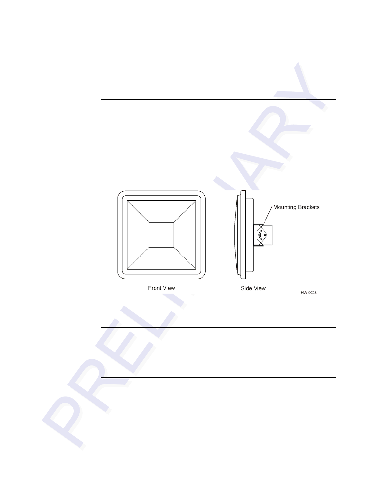
A second version of the Encompass 4/4800 Multiprotocol Reader is designed to be
used with a high-performance external antenna. These Encompass 4/4800 Multiprotocol Reader System components are contained in a highly reliable, compact, and easyto-install environmentally-sealed package. Figure 1-1 shows the front and side views
of an Encompass 4/4800 Multiprotocol Reader System.
1-6
Figure 1-1 Encompass 4/4800 Multiprotocol Reader System Front and Side
Views
Tags
The Encompass 4/4800 Multiprotocol Reader System has the capability to read the
Intellitag-based eGo Windshield Sticker Tag as well as TransCore ATA protocol and
TransCore ISO-compliant read-only full- and half-frame tags.
How It Works
The Encompass 4/4800 Multiprotocol Reader System directs the RF module to generate an RF signal, which is broadcast through the internal or external antenna. Entering
the Encompass 4/4800 Multiprotocol Reader System’s reading range, a TransCore
RFID tag installed on a vehicle or other object to be tracked adds its programmed
identification information to the signal and reflects the signal back to the Encompass
4/4800 Multiprotocol Reader System. The Encompass 4/4800 Multiprotocol Reader
System receives this modified, or modulated signal, and decodes the tag data carried
by the reflected signal and transmits this data to a local host computer for processing.
Page 29

Licensing Requirements
An FCC license provides the user with the legal authorization to operate the Encompass 4 on the licensed frequencies at the site specified in the license. Only an authorized installer or service technician can set the RF frequency of the Encompass 4/4800
Multiprotocol Reader System to the frequency specified in the FCC site license. No
end-user-operated controls exist on the Encompass 4/4800 Multiprotocol Reader System.
The FCC license also provides the user with protection and authorization to maintain
the system should any other RFID product be used in the licensed area after the
Encompass 4/4800 equipment is installed.
Users of the Encompass 4/4800 Multiprotocol Reader System in the United States
must obtain a license from the FCC. The authorized frequency band for this product in
the United States is 912.5 to 919 MHz.
The user is responsible for filing the FCC license according to FCC regulations, but
the TransCore dealer will provide assistance and support as necessary to complete
these forms. Forms are available online at the FCC internet site http://www.fcc.gov/
formpage.html. For further information on obtaining the license contact TransCore.
Introduction
Technical Support
Authorized dealers and distributors are responsible for the direct support of all
customers. Authorized dealers and distributors needing technical support can contact:
Technical Support
Phone: (800) 755-0378
Web: transcore.com/rfidsupport
or
TransCore
3410 Midcourt Road, Suite 102
Carrollton, Texas 75006 USA
Phone: (214) 461-4031
Fax: (214) 461-6478
Please be prepared to answer a series of questions that are designed to direct you to the
best support resource available.
1-7
Page 30

Encompass 4/4800 Multiprotocol Reader System Guide
1-8
Page 31

2
Developing the Site Plan
Page 32

Page 33

Overview
Chapter 2
Developing the Site Plan
This chapter discusses site plan development for installing the
TM
Encompass
Developing a site plan provides the foundation for the site’s system design and es tablishes the following system configuration parameters:
• Number and general location of primary components
• Number of different radio frequencies required
Gathering relevant site information is crucial before applying for Federal Communications Commission (FCC) approval and ordering and installing Encompass 4/4800
Multiprotocol Reader(s) and tags.
Also, consider the following factors when developing a site plan:
4/4800 Multiprotocol Reader System.
• Type of tags used in the facility
• Reader and/or antenna and tag alignment
• Site layout and traffic flow
• Encompass 4/4800 Multiprotocol Reader and/or antenna mounting requirements
• Encompass 4/4800 Multiprotocol Reader electrical requirements
• Encompass 4/4800 Multiprotocol Reader communications requirements
These factors provide relevant information regarding each site’s physical and electromagnetic environment and the conditions under which the system must perform.
Reading of Mixed Population Tags
The Encompass 4/4800 Multiprotocol Reader reads the American Trucking Association (ATA) and International Organization for Standardization (ISO) read-only tags,
whether powered by battery or beam, or application-specific integrated circuit
(ASIC)-based tags with Intellitag technology. The reader can read the ATA or ISO
read-only tags in the presence of Intellitag-based tags; however, attempting to read an
Intellitag-based tag in the presence of an ATA or ISO read-only tag is not recommended.
2-3
Page 34

Encompass 4/4800 Multiprotocol Reader System Guide
Caution
Attempting to read an Intellitag-based tag in the presence of an ATA or ISO read-only
tag may provide unreliable results.
The factors that influence the readability include, but are not limited to physical orientation and configuration, type of read-only tag, ratio of backscatter cross-section of the
tags, and whether the tag is battery- or beam-powered.
Reader and Tag Alignment
The position of the Encompass 4/4800 Multiprotocol Reader and placement of the tag
on the vehicle must be compatible. Also, consider any existing tagged vehicles now
using the facility to determine the optimal Encompass 4/4800 Multiprotocol Reader
location and orientation at the site.
Note: If any of the vehicles using your facility already have tags, such as those used
in toll applications, contact TransCore at 1-800-755-0378 for information about
mixed-tag installations before you plan tag type, location, and programming.
Three primary criteria must be satisfied to achieve the highest read reliability:
• Polarization of the tag and the Encompass 4/4800 Multiprotocol Reader must be
aligned in the same direction
— both horizontal.
• The installed tag must be in a direct, unobstructed line of sight to the Encompass
4/4800 Multiprotocol Reader .
• T ags desig ned to be mo unted in a vehicle wind shield must be mo unted in the veh i-
cle’s windshield, and tags designed to be mounted on the exterior surface of the
vehicle must be mounted on the exterior surface of the vehicle.
Caution
A tag may not be reliably read unless the preceding criteria are met.
2-4
Page 35

Developing the Site Plan
Polarization
The polarization of the tag must be aligned in the same direction as the Encompass
4/4800 Multiprotocol Reader, as shown in Figure 2-1.
Note: Matching the tag and antenna polarization is critical to obtain optimal system
performance.
Figure 2-1 Tag and Reader Orientation
2-5
Page 36

Encompass 4/4800 Multiprotocol Reader System Guide
Unobstructed Line of Sight
For optimum readability, install the Encompass 4/4800 Multiprotocol Reader and the
vehicle’s tag so that when the vehicle approaches the Encompass 4/4800 Multiprotocol Reader, the tag is directly facing the reader and the line of sight is clear between
the Encompass 4/4800 Multiprotocol Reader and the tag. If a fence or barrier is
between the tag and the reader, the Encompass 4/4800 Multiprotocol Reader cannot
reliably read the tags. Figure 2-2 illustrates possible installation locations of an
Encompass 4/4800 Multiprotocol Reader in relation to a tag’s mounting location on a
vehicle. If the tags are not in the recommended location, reliable optimum operation
requires lower vehicle speeds.
2-6
Figure 2-2 Encompass 4/4800 Multipr otocol Reader Location Relative to Tag
Position
Page 37

Developing the Site Plan
If the Encompass 4/4800 Multiprotocol Reader is installed on a pole or wall to the left
of the vehicle, optimal tag position is on the left side of the vehicle as illustrated in
Figure 2-3.
Figure 2-3 Typical Tag Positions for U.S. Driver’s Side Reader
If an Encompass 4/4800 Multiprotocol Reader is installed on a pole or wall to the right
of the vehicle, optimal tag position is on the right side of the vehicle as illustrated in
Figure 2-4.
Figure 2-4 Typical Tag Positions for U.S. Passenger’s Side Reader
2-7
Page 38

Encompass 4/4800 Multiprotocol Reader System Guide
If the Encompass 4/4800 Multiprotocol Reader is installed in an overhead location,
optimal tag position is in the top center of the windshield in the area behind the rear
view mirror or on the vehicle’s front license plate or center bumper as illustrated in
Figure 2-5.
Figure 2-5 Typical Tag Positions Used with Overhead Reader
Note: Metallized coatings on some vehicle windshields and windows shield the RF
energy emitted by the Encompass 4/4800 Multipr otocol Reader and may cause tags to
be misread. Many metallized windshields have areas that are not metallized in which
the tag can be placed and reasonable results achieved. If there are no openings in the
metallized coating in which to install an interior tag, install exterior-type tags on the
exterior of the vehicle.
Refer to Chapter 3 “Choosing, Installing, and Removing Tags” for more detailed
information on tag positioning.
Antenna Selection
This section contains guidelines that assist in antenna selection for an Encompass
4/4800 Multiprotocol Reader installation that uses an external antenna. The following
antennas are compatible with the Encompass 4/4800 Multiprotocol Reader installation.
AA3100 Yagi (without radome)
Appropriate for installations with the following requirements and conditions:
2-8
• 902 to 928 MHz operation
• Non-icing environments
Page 39

Developing the Site Plan
• Relatively symmetrical reading range
• Antenna profile not a major consideration
AA3101 Yagi (with radome)
Appropriate for installations with the following requirements and conditions:
• 902 to 928 MHz operation
• Exposure to harsh environments
• Relatively symmetrical reading range
• Antenna profile not a major consideration
AA3110 Parapanel
Appropriate for installations with the following requirements and conditions:
• 902 to 928 MHz operation
• Exposure to harsh environments
• Broad radiation pattern in one dimension, narrow in the other
• Low antenna profile
• Horizontal polarization
AA3140 PCB Log Periodic
Appropriate for installations with the following requirements and conditions:
• 845 to 950 MHz operation
• Exposure to harsh environments
• Maximum coverage at close range (<20 ft [6.1 M])
• Vertical or horizontal polarization
AA3152 Universal Toll Antenna
Appropriate for installations with the following requirements and conditions:
• 902 to 928 MHz operation
• Exposure to harsh environments
• Broadcast pattern of similar size and shape in both horizontal and vertical planes
• Low antenna profile
2-9
Page 40

Encompass 4/4800 Multiprotocol Reader System Guide
AA3153 Toll Antenna
Appropriate for installations with the following requirements and conditions:
• 902 to 928 MHz operation
• Exposure to harsh environments
• Broadcast pattern with virtually no side or back lobes, which helps confine cover-
age to a single lane width
• Low antenna profile
Antenna and Tag Alignment
The position of the antenna connected to the Encompass 4/4800 Multiprotocol Reader
and placement of the tag on the vehicle must be compatible. Also, consider any existing tagged vehicles now using the facility to determine the optimal Encompass 4/4800
Multiprotocol Reader antenna location and orientation at the site.
Note: If any of the vehicles using your facility already have tags, such as those used
in toll applications, contact TransCore at 1-800-755-0378 for information about
mixed-tag installations before you plan tag type, location, and programming.
Three primary criteria must be satisfied to achieve the highest read reliability:
• Polarization of the tag and the Encompass 4/4800 Multiprotocol Reader antenna
must be aligned in the same direction — both horizontal or both vertical.
• The installed tag must be in a direct, unobstructed line of sight to the Encompass
4/4800 Multiprotocol Reader antenna.
• T ags desig ned to be mo unted in a vehicle wind shield must be mo unted in the veh i-
cle’s windshield, and tags designed to be mounted on the exterior surface of the
vehicle must be mounted on the exterior surface of the vehicle.
Caution
A tag may not be reliably read unless the preceding criteria are met.
Polarization
The polarization of the tag must be aligned in the same direction as the antenna connected to the Encompass 4/4800 Multiprotocol Reader, as shown in Figure 2-1.
2-10
Note: Matching the tag and antenna polarization is critical to obtain optimal system
performance.
Page 41

Developing the Site Plan
.
Figure 2-1 Horizontal and Vertical Tag Orientation
A horizontally oriented antenna cannot read a vertically oriented tag and vice versa.
Unobstructed Line of Sight
For optimum readability, install the Encompass 4/4800 Multiprotocol Reader antenna
and the vehicle’s tag so that when the vehicle approaches the antenna, the tag is
directly facing the antenna and the line of sight is clear between the antenna and the
tag. If a fence or barrier is between the tag and the antenna, the antenna cannot reliably
read the tags. Figure 2-2 illustrates possible installation locations of an Encompass 4/
4800 Multiprotocol Reader antenna in relation to a tag’s mounting location on a vehicle. If the tags are not in the recommended location, reliable optimum operation
requires lower vehicle speeds.
2-11
Page 42

Encompass 4/4800 Multiprotocol Reader System Guide
Figure 2-2 Antenna Location Relative to Tag Position
Site Layout and Traffic Flow
The following site layout and traffic flow considerations are critical when determining
Encompass 4/4800 Multiprotocol Reader installation locations:
• The Encompass 4/4800 Multiprotocol Reader read zone
• Other Encompass 4/4800 Multiprotocol Reader units and antennas in the area
• Lane configurations
• Reflection, refraction, and diffraction of RF signals
• Existing signal interference at the site
2-12
Page 43

Developing the Site Plan
The Encompass 4/4800 Multiprotocol Reader Read Zone
The Encompass 4/4800 Multiprotocol Reader must be able to read the tag data properly within a specified area, called the read zone, without reading other nearby tags or
interfering with other Encompass 4/4800 Multiprotocol Readers at the site. The following are some of the factors that affect the size and shape of the read zone:
• Mounting method used (pole or wall mount)
• Mounting location (overhead or side mount)
• Height from the ground and mounting angle
• Mounting method used (pole or wall mount) of the antenna
• Mounting location (overhead or side mount) of the antenna
• Height from the ground and mounting angle of the antenna
• Indoor or outdoor location
• RF output attenuation
• Range discrimination setting
• Other sources of interference and reflection
The Encompass 4/4800 Multiprotocol Reader must be positioned to allow the RF signal to travel to and return from the tags within the designated range and be placed in
an area where it is not likely to be bumped out of alignment. If the antenna becomes
misaligned or some nearby structure is added or removed, system operation can be
seriously affected.
The external antenna must be positioned to allow the RF signal to travel to and return
from the tags within the designated range and be placed in an area where it is not
likely to be bumped out of alignment. If the antenna becomes misaligned or some
nearby structure is added or removed, system operation can be seriously affected.
For instructions on setting the read zone, see “Fine-Tuning and Verifying the Read
Zone” on page 8-20.
Other Encompass 4/4800 Multiprotocol Readers in the Area
Sites with more than one Encompass 4/4800 Multiprotocol Reader in proximity
should have them configured with a frequency separation of at least 2 MHz from adjacent readers. If more than one Encompass 4/4800 Multiprotocol Reader is in a sideby-side or multiple lane application, the frequencies should be staggered. Also,
Encompass 4/4800 Multiprotocol Readers may not operate accurately if they directly
face each other or are positioned back-to-back.
2-13
Page 44

Encompass 4/4800 Multiprotocol Reader System Guide
If more than one Encompass 4/4800 Multiprotocol Reader and antenna is in a side-byside or multiple lane application, the frequencies should be staggered. Also, Encompass 4/4800 Multiprotocol Readers may not operate accurately if the antennas directly
face each other or are positioned back-to-back.
T a ble 2-1 shows examples of staggered reader frequencies in a site with up to 14 readers.
Table 2-1 Examples of Staggered Reader Frequencies
Lane Number Reader Frequency Lane Number Reader Frequency
1912.52915
3 917.5 4 913.5
5 916 6 918.5
7914.58917
9 913 10 915.5
11 918 12 914
13 916.5 14 919
Lane Configurations
TransCore recommends that traffic be guided through a controlled lane to consistently
obtain accurate tag readings and to prevent physical damage to the Encompass 4/4800
Multiprotocol Reader . The following subsections describe some common lane configurations and offer suggestions for positioning the Encompass 4/4800 Multiprotocol
Reader within the controlled traffic flow.
Gate with Center Island Configuration
Figure 2-3 illustrates a typical gate application with the Encompass 4/4800 Multiprotocol Reader units positioned on a center island to read tags mounted on the inside
windshield on the driver’s side (United States). The readers are placed to allow time
for the gate to open so the vehicle can roll through without stopping while not allowing room for an untagged vehicle to be between the vehicle being read and the gate.
2-14
Page 45

Developing the Site Plan
Figure 2-3 Gate Application with Center Island
Parking Garage with Ticket Island Configuration
Figure 2-4 illustrates a parking garage application with each Encompass 4/4800 Multiprotocol Reader mounted on the ticket island to read tags mounted on the inside center windshield or on the center front vehicle bumper. The Encompass 4/4800
Multiprotocol Reader placement may require the vehicle to stop before the gate opens.
2-15
Page 46

Encompass 4/4800 Multiprotocol Reader System Guide
Figure 2-4 Parking Garage Application
Overhead Reader Installation Configuration
Another option for Encompass 4/4800 Multiprotocol Reader placement is to mount it
overhead in each lane as illustrated in Figure 2-5. This illustration assumes that tags
are mounted on the inside center windshield or center bumper of the vehicle.
2-16
Figure 2-5 Overhead Installation
Page 47

Developing the Site Plan
Lane Configurations for Encompass 4/4800 Multiprotocol Readers Using an External Antenna
TransCore recommends that traffic be guided through a controlled lane to consistently
obtain accurate tag readings and to prevent physical damage to the Encompass 4/4800
Multiprotocol Reader and antenna. The following subsections describe some common
lane configurations and offer suggestions for positioning the external antenna within
the controlled traffic flow.
Gate with Center Island Configuration
Figure 2-3 illustrates a typical gate application with the readers and antennas positioned on a center island to read tags mounted on the inside windshield on the driver’s
side (United States). The antennas are placed to allow time for the gate to open so the
vehicle can roll through without stopping while not allowing room for an untagged
vehicle to be between the vehicle being read and the gate.
Figure 2-6 Gate Application with Center Island
2-17
Page 48

Encompass 4/4800 Multiprotocol Reader System Guide
Parking Garage with Ticket Island Configuration
Figure 2-4 illustrates a parking garage application with each Encompass 4/4800 Multiprotocol Reader and antenna mounted on the ticket island to read tags mounted on
the inside center windshield or on the center front vehicle bumper. The Encompass 4/
4800 Multiprotocol Reader antenna placement may require the vehicle to stop before
the gate opens.
Figure 2-7 Parking Garage Application
Overhead Reader Installation Configuration
Another option for Encompass 4/4800 Multiprotocol Reader antenna placement is to
mount it overhead in each lane as illustrated in Figure 2-5. This illustration assumes
that tags are mounted on the inside center windshield or center bumper of the vehicle.
2-18
Page 49

Developing the Site Plan
Figure 2-8 Overhead Installation
Reflection, Refraction, and Diffraction of RF Signals
RF signals can be reflected, refracted, or diffracted by metal objects, walls, and even
wet pavement or ice. Any of these factors can alter or degrade system performance.
When designing your site plan, you must consider permanent structures and transient
factors in the vicinity that may affect RF signals being generated by the Encompass 4/
4800 Multiprotocol Reader. Permanent structures include buildings, chain link fences,
guard shacks, and gates. Transient factors include passing traffic and local weather
conditions, such as rain or snow. Symptoms of reflection, refraction, and diffraction
include reading tags that are out of the desired read zone or tags being read from
another lane.
The most common RF reflectors are metallic surfaces. RF signals may also be partially reflected by nonconducting materials such as dirt, wood, ice, asphalt, and concrete. When nonconducting materials in the system environment become wet, they
increase reflection of RF signals.
The Encompass 4/4800 Multiprotocol Reader and/or antenna mounting location, aiming, and range control adjustment, and use of presence detectors can reduce interference from RF reflections. When these actions cannot adequately control reflections,
other techniques such as shielding, absorbing, range sensitivity adjustment, or barriers
can also be used. See Chapter 9, “Troubleshooting and Maintenance” for more infor-
mation.
2-19
Page 50

Encompass 4/4800 Multiprotocol Reader System Guide
Existing Interference
Interference from RF and electrical sources can degrade system performance and must
also be considered in the site design. Fluorescent lights, neon signs, nearby radio stations, or power lines can interfere with the optimal operation of the system. The magnetic impulse noise from relays that control gate opening and closing can also disrupt
the RF signal.
Interference may degrade both reader and tag performance. Existing interference at
the site may be shielded, removed, or positioned further from the Encompass 4/4800
Multiprotocol Reader and/or antenna. In some cases, changing the operating frequency of the Encompass 4/4800 Multiprotocol Reader may provide a simple solution. Readers in proximity should have at least a 2 MHz frequency separation. See
“Other Encompass 4/4800 Multiprotocol Readers in the Area” on page 2-13. Strong
RF sources of any frequency, in proximity to the tag, can preclude the tag receiving
the reader interrogation. See Chapter 9, “Troubleshooting and Maintenance.”
Electrical and Communications Requirements
All construction work at the site must be completed before installing the Encompass
4/4800 Multiprotocol Reader . Electrical and communications cables should be
installed according to all applicable local and federal building code requirements. Specific instructions for positioning and installing the Encompass 4/4800 Multiprotocol
Reader are discussed in Chapter 4, “Installing the Encompass 4/4800 Multiprotocol
Reader .”
Junction Box
Use a watertight junction box that meets applicable local and national building codes
for connecting power and communications wiring. The junction box houses the terminal strip for power and communications connections. TransCore recommends a
NEMA Type-4 junction box with a back mounting panel.
Power and Communications Cables
Cable length for power and communications depends on the physical characteristics
of the Encompass 4/4800 Multiprotocol Reader installation site. Table 2-1 lists accessory kits available for cabling options based on your site’s requirements.
Table 2-1 Connector Cabling Accessory Kits
2-20
Part Number Description
58-1620-001 5-ft connector cable harness
58-1620-002 20-ft connector cable harness
Page 51

Developing the Site Plan
Table 2-1 Connector Cabling Accessory Kits (continued)
Part Number Description
20-1620-003 Connector kit only
56-1620-004 13-pair cable (sold by the foot)
76-1620-005 110V AC to 18V AC Class C transformer
76-1620-006 12V AC to 18V AC step-up transformer
Electrical Power
A dedicated electrical power supply must be present at the site and available to the
Encompass 4/4800 Multiprotocol Reader at all times. The power must be 16-20V AC
or 16-28V DC. A step-down transformer is available (North America only) to convert
a 120V AC duplex wall outlet with ground to 18V AC, as is a step-up transformer to
convert a low-voltage 12V AC outlet to 18V AC. Consult your local and national electrical codes for installation and safety requirements.
Note: Encompass 4/4800 Multiprotocol Readers installed outside North America
require a locally supplied transformer.
If 18V AC or 18V DC power is available, the transformer option is unnecessary.
TransCore offers a Class C transformer accessory kit (part number 76-1620-005) for
sites where 110V AC is available. It is the installer’s responsibility to supply conversion equipment and wiring for other voltages. T a ble 2-2 contains power supply current
requirements.
Table 2-2 Power Supply Current Requirements
(RF On)
Supply
16 to 20V AC 1.7 A at 18V AC 1 A at 18V AC
16 to 28V DC 1.7 A at 18V DC 1 A at 18V DC
Worst Case
Maximum Current at
68°F (20°C)
(RF Off)
Standby Operating
Current at 68°F
(20°C)
Power circuits are protected internally against power surges.
Power Extension
Use Table 2-3 to determine the correct cable size according to the American Wire
Gauge (AWG) standard for the necessary length of extension cable. The numbers in
the first row of the table indicate cable size for the approximate cable length .
Note: If the cable is close to the ma xim u m len gth, measure voltage at the Encompass
4/4800 Multiprotocol Reader with RF ON to ensure voltage does not drop below 16V.
A drop in voltage below 16V causes a reduction in read range and possible damage to
internal electronics as well as unreliable operation.
2-21
Page 52

Encompass 4/4800 Multiprotocol Reader System Guide
Table 2-3 Recommended Ca ble Length from Transformer to the Encompass 4/4800 Mul ti protocol
Reader
Cable Size (AWG)
Maximum DCR (Ohms
per foot at 68
°F)
b
a
24 22 20 18 16 14 12
0.0270 0.0175 0.0109 0.0069 0.0044 0.0027 0.0017
Maximum length (feet) 29.63 45.71 73.39 115.61 183.91 293.04 467.84
Maximum length (feet)
When used to extend
c
25 39 62 98 156 249 398
23 36 57 90 143 227 363
TransCore 5-ft cable
(feet)
When used to extend
14 22 35 55 88 140 224
TransCore 20-ft cable
(feet)
a. Use two conductors each for 18V and 18V return (4 conductors total on the TransCore cable
harness).
b. Direct current resistance (DCR) information is from the Belden catalog.
c. Calculated length is reduced by -15% to adjust for other variables such as connector contact
resistance. Length v ariable factor is 85%; maximum current drawn by the Encompass 4/4800
Multiprotocol Reader is 2.5 amps; maximum allowable voltage drop from the 18V AC trans-
former secondary is 2V.
2-22
Page 53

Developing the Site Plan
Host Communications
Your site design must include communications between the Encompass 4/4800 Multiprotocol Reader and a host computer. The Encompass 4/4800 Multiprotocol Reader
communicates with the host computer through an asynchronous serial line or through
a Wiegand interface. This serial line can be an
–232 interface or an RS–422 interface. The host computer must be able to accept
RS
one of the interfaces shown in Table 2-4.
Table 2-4 Communicat ions Interfaces and Conductor Requirements
Interface
–232 3
RS
RS
–232 with RTS and CTS hardware and handshake
signals
RS
–422 4
Wiegand 3
Number of
Conductors
5
RS–232 Interface
Use an RS–232 interface if one or more of the following conditions apply to your site:
• The host computer system is 50 ft (15.2 m) or less from the Encompass 4/4800
Multiprotocol Reader .
• The host computer system is more than 50 ft (15.2 m) from the Encompass 4/4800
Multiprotocol Reader and a pair of RF modems or limited distance modem/line
drivers over copper wire are used for communications between the Encompass 4/
4800 Multiprotocol Reader and the host. The distance from the RF modem to the
Encompass 4/4800 Multiprotocol Readershould not exceed 50 ft (15.2 m).
• Other common communications devices that can extend the RS–232 distance,
such as fiber optic modems, have been selected.
The standard RS
type, and the RS
–232 connection maximum distance depends on the baud rate, cable
–232 device at the other end.
RS–422 Interface
Use an RS–422 interface if one or more of the following conditions apply to your site:
• The host computer is more than 50 ft (15.2 m) from the Encompass 4/4800 Multi-
protocol Reader .
• The host computer has an external limited-distance modem.
2-23
Page 54

Encompass 4/4800 Multiprotocol Reader System Guide
The standard RS
type, and the RS
–422 connection maximum distance depends on the baud rate, cable
–422 device at the other end.
Wiegand Interface
The Encompass 4/4800 Multiprotocol Reader can interface with equipment requiring
the Wiegand +5V DC data0-data1-ground interface. The reader uses the Wiegand
interface included with the RS
Note: The Encompass 4/4800 Multiprotocol Reader comes from the factory with
either RS
must first connect the Encompass 4/4800 Multiprotocol Reader using the RS
RS
Encompass 4/4800 Multiprotocol Reader ’s configuration to Wiegand, and then connect the Encompass 4/4800 Multiprotocol Reader to the Wiegand interface.
Note: You must order tags programmed with Wiegand-formatted data when using a
Wiegand-compatible reader.
–232 and W iegand or RS–422 and Wiegand. If you wish to use Wiegand, you
–422 interface, set all necessary operating parameters in the reader, then set the
–232 or RS–422 option.
–232 or
Input/Output Circuits
To connect the Encompass 4/4800 Multiprotocol Reader to external equipment such
as a treadle or traffic control light, install wires from these devices at the junction box.
The Encompass 4/4800 Multiprotocol Reader input circuit is designed to connect to a
dry contact closure. The Encompass 4/4800 Multiprotocol Reader output circuits are
single-pole, double-throw relays providing dry contact closures. These contacts are
rated at 42.2V AC peak (30V
load.
) or 60V DC, at 1 A maximum with noninductive
rms
2-24
Output circuits are not intended for the direct control of electromechanical devices
such as motorized gates and barrier arms. For such applications, the Encompass 4/
4800 Multiprotocol Reader output circuits should be used to drive a secondary, appropriately rated high-power relay.
Antenna Interface
The site design must include an interface cable between the Encompass 4/4800 Multiprotocol Reader and the compatible antenna chosen for the site. The antenna interface
is RF coaxial cable with male Type N sockets on each end.
Table 2-5 is a summary of coaxial cable performance. Figures indicate maximum
lengths of cable in feet.
Page 55

Table 2-5 Reader to Antenna Cable Performance
Developing the Site Plan
Cable Type
RG–223 0.216 6 18
RG
–214 0.425 12 37
FHJ1
–50 0.250 16 48
FSJ1
–50 0.250 15 45
LDF2
–50 0.375 28 85
FSJ4
–50B 0.500 27 83
LDF4
–50A 0.500 42 128
LDF5
–50A 0.875 76 229
LDF6
–50 1.125 103 310
LDF7
–50A 1.625 122 366
a. Suffixes 50, 50A, and 50B indicate 50-ohm cables availabl e from the
Andrew Corporation.
b. These cab le lengths ensure optimal system performance (1 dB loss).
c. These cable lengths ensure adequate, but not optimal, system performance (3 dB
loss).
a
Overall
Diameter (in.)
915MHz
Low Medium
Loss
b
Loss
c
2-25
Page 56

Encompass 4/4800 Multiprotocol Reader System Guide
2-26
Page 57

3
Choosing, Installing, and Removing
Tags
Page 58

Page 59

Choosing, Installing, and Removing Tags
This chapter describes the various tag types compatible with the
Encompass
installing and removing compatible internal and external tags.
Compatible Tag Types
The Encompass 4/4800 Multiprotocol Reader provides the capability to read the various TransCore eGo tags and other American National Standards Institute (ANSI)
ANS INCITS 256-2001-compliant tags with Intellitag technology. Depending on
options ordered, the Encompass 4/4800 Multiprotocol Reader can read eGo tags as
well as TransCore IT2000 (in opti onal AT A/ISO mode), ATA-protocol, ISO-compliant
tags, and eGo Plus tags when they are programmed to operate in ATA mode. It can
also read tags formatted to a wide range of industry-standard proprietary formats,
including SIA Wiegand 26-bit standard format.
The Encompass 4/4800 Multiprotocol Reader reads only the various TransCore eGo
tags.
TM
4/4800 Multiprotocol Reader and the procedures for
Chapter 3
See Appendix E for information about the numerous ATA-protocol tag models.
Reader and Tag Model Interoperability
Table 3-1 lists the tags that are read by the Encompass 4/4800 Multiprotocol Reader.
See http://www.transcore.com/pdf/Tag-Reader-Matrix.pdf for most current information concerning readers and supported tag protocols.
Table 3-1 Tags Read by the Encompass 4/4800 Multiprotocol Reader
Reader Beam Tags Battery Tags
Encompass 4/4800 Multiprotocol
Reader
AT5100; AT5102; AT5110;
AT5112; AT5125; AT5145;
AT5146; AT5715
eGo Windshield Sticker Tag;
eGo Tamper Resistant Tag; eGo
License Plate Tag
eGo Plus Sticker* Tag; eGo Plus
License Plate Tag*
other ANS INCITS 256-2001compliant tags with Intellitag
technology
AT5105; AT5114; AT5140;
AT5147; AT5510; AT5540;
AT5541; AT5542; AT5543;
AT5544; AT5545; AT5547;
AT5704; AT5707; IT2221**;
IT2235**
* in ATA and eGo modes ** When used in optional ATA/ISO
mode
3-3
Page 60

Encompass 4/4800 Multiprotocol Reader System Guide
TransCore’s eGo Tags
TransCore’s various eGo tags are offered to complete your Encompass 4/4800 Multiprotocol Reader System.
Table 3-2 lists some of the features of the TransCore eGo tags.
Table 3-2 eGo Tag Features
Tag
Windshield
Sticker Tag
License
Plate Tag
Part
Number
13-0510004
13-0510900
Used For
Toll,
Electronic
vehicle
registration
(EVR),
mCommerce,
Parking,
Security
access
Special
Features
Very thin,
flexible,
multi-layer
lamination
Waterresistant,
exteriormounted
Number
Power
Source
Beam 20 1 NA
of 6-bit
ASCII
Characters
10 1/2 26 to 54
20 1 NA
10 1/2 26 to 54
Number
of 128-
Bit
Frames
Number
of
Wiegand
Bits
eGo Windshield Sticker Tag
The TransCore eGo Windshield Sticker Tag (Figure 3-1) is offered to complete your
Encompass 4/4800 Multiprotocol Reader System. It is a flexible sticker much like a
vehicle registration sticker.
3-4
Figure 3-1 eGo Windshield Sticker Tag
Page 61

Choosing, Installing, and Removing Tags
eGo Plus Sticker Tag
The Encompass 4/4800 Multiprotocol Reader can also read the eGo Plus Sticker Tag
configured to support ATA or eGo modes.
Figure 3-2 eGo Plus Windshield Sticker Tag
eGo License Plate Tag
The eGo License Plate Tag (Figure 3-3) is a water-resistant tag used in applications
requiring an exterior-mounted eGo tag.
Figure 3-3 eGo License Plate Tag
3-5
Page 62

Encompass 4/4800 Multiprotocol Reader System Guide
Intellitag Data Format
The memory of Intellitag-based tags consists of 128 bytes of non-volatile read/write
memory. Portions of tag data, such as the tag serial number, manufacturing location
code, and tag hardware type, are programmed at the factory and locked. The tag memory layout may be programmed by the end user and may be ke pt unlocked if desired.
Of the 128 bytes of memory, 12 bytes are programmed and locked at the factory and
116 bytes of user memory are available to be formatted and locked as required by the
application. Six bytes of the available 116 bytes of user memory are used for defining
tag memory layout.
Tags can be programmed in Wiegand formats with 26 to 54 bits. Users who choose
this tag data format must complete a Wiegand format worksheet — attached to the
Encompass 4/4800 Multiprotocol Reader order entry form — indicating the data to be
programmed into the tags.
Installing eGo Windshield Sticker Tags
eGo Windshield Sticker Tags are designed to be attached by a semi-permanent adhesive to the interior surface of nonmetallic windshields 0.190 to 0.230 inches (4.82 to
5.84 mm) in thickness. For optimum performance, you must install the tag at least 2
inches (5 cm) from the metal in the windshield frame and 0.75 inch (1.9 cm) from the
rearview mirror support post. Detailed instructions are found in the pocket guide
"Quick and Easy Installation Instructions for Windshield Sticker Tag."
Some vehicles have a tinted area across the top of the windshield. If the tint is conductive, it can interfere with reading the tag. If a windshield has this conductive tint, the
tag must be installed at least 2 inches (5 cm) below this tinted area.
Some vehicle windshields contain a metallic treatment that could prevent an interior
windshield-mounted tag from being read. However, many of these metallized windshields have areas that are not metallized. On a vehicle without open areas in its metallized windshield, you might need to install an Encompass 4/4800 Multiprotocol
Reader-compatible license plate tag on the vehicle. See the section “Installing eGo
License Plate Tags” on page 3-9 and the section “Installing ATA License Plate Tags”
on page 3-15. Contact TransCore for more information. See the section “Technical
Support” on page 9-7.
eGo Plus Sticker T ags are posit ioned and installed similarly to eGo W indshield Sticker
T ags. Detailed instructions are found in the pocket guide "Quick and Easy Installation
Instructions for the eGo
®
Plus Sticker Tag."
3-6
Required Materials
You need the following supplies to install windshield sticker tags:
• Glass cleaner, mild detergent and water, or any cleaning solution appropriate for
your windshield
• Clean, dry cloth
Page 63

Choosing, Installing, and Removing Tags
• eGo Windshield Sticker Tag
Positioning eGo Windshield Sticker Tags
TransCore designed the eGo Windshield Sticker Tag to be installed o n the upper center or upper corner portion of the windshield. Figures Figure 3-4, Figure 3-5, and Fig-
ure 3-6 illustrate possible upper center tag placement locations. If the upper portion
of the windshield is tinted with an aftermarket conductive tint, use placement
Option B as shown in Figure 3-5.
Mirror Post Attached Low On Windshield
Choose placement Option A shown in Figure 3-4 if the mirror post is attached low on
the windshield.
Figure 3-4 eGo Windshield Sticker Tag Placement Option A
Mirror Post Attached High on Windshield
Choose placement Option B if the mirror post is attached high on the windshield as
shown in Figure 3-5 or if the upper portion of the windshield is tinted with a conductive tint.
3-7
Page 64

Encompass 4/4800 Multiprotocol Reader System Guide
Figure 3-5 eGo Windshield Sticker Tag Placement Option B
Mirror Post Attached to Headliner
Choose placement Option C if the mirror post is attached to the headliner as shown in
Figure 3-6. If the upper portion of the windshield is tinted with an aftermarket
conductive tint, place the tag two inches (5 cm) below the tinted area.
Figure 3-6 eGo Windshield Sticker Tag Placement Option C
eGo Windshield Sticker Tag Installation Procedures
Caution
Confirm that the outside temperature is above 50°F (10°C). The sticker tag may not
adhere correctly if the temperature is below this temperature.
3-8
Page 65

Choosing, Installing, and Removing Tags
To install the eGo Windshield Sticker Tag
1. Determine the tag installation location for the vehicle using the placement
guidelines in the section “Positioning eGo Windshield Sticker Tags” on page 3-7.
2. Thoroughly clean the interior surface of the windshield behind and around the
rearview mirror where the tag will be located.
3. Dry the tag location area thoroughly using a clean, dry cloth.
4. Remove the paper backing from the tag to expose the adhesive.
Caution
Ensure that the tag is correctly located before touching it to the glass. Once the
sticker tag is applied to the glass, it cannot be moved without damage to the tag.
5. Holding the sticker tag by its edges, position the tag in the correct area of the
windshield (determined in Step 1), making sure the tag is oriented horizontally
and is at least two inches (5 cm) from the windshield frame and 0.75 inch (1.9
cm) from the mirror post.
6. Press the sticker tag firmly against the glass and gently rub over the entire tag
surface. Ensure that no air bubbles remain between the sticker tag and the
windshield.
Removing eGo Windshield Sticker Tags
Removing eGo Windshield S ticker Tags requires the use of a razor blade or equivalent
tool. The tag is inoperable once removed.
Installing eGo License Plate Tags
Metallized coatings on some vehicle windshields and windows absorb the RF energy
emitted by the Encompass 4/4800 Multiprotocol Reader, thus causing tags to be misread. You must use exterior license plate tags on vehicles with metallized coatings on
their windshields and windows.
Use license plate installation techniques to install tags on the exterior of vehicles that
have this type of window coating.
Note: The read zone of an overhead Encompass 4/4800 Multiprotocol Reader should
be adjusted accordingly when an exterior tag is installed on a license plate, or the
read zone will be reduced.
Required Materials
• Screwdriver (flat-blade or Phillips depending on the vehicle’s license plate
mounting screws)
3-9
Page 66

Encompass 4/4800 Multiprotocol Reader System Guide
• Optional TransCore Exterior Tag Accessory Kit (19077-01). This kit contains
tamper-resistant mounting screws and wrench.
• eGo License Plate Tag
Positioning eGo License Plate Tags
The eGo License Plate Tag (LPT) is installed over the license plate at the upper part of
the vehicle’s front license plate area.
Note: If your state does not require a front license plate, install the LPT in the area
where the license plate would normally be mounted. If your vehicle does not have a
front license plate area, contact your tag agency for other tag options.
The orientation of the tag is important. The tag must be mounted so that the holes on
the tag base plate are on the top edge.
3-10
Page 67

Choosing, Installing, and Removing Tags
eGo License Plate Tag Installation Procedures
To mount the eGo LPT
1. Remove the screws from the license plat e area of your front bumper (Figu re 1). If
your vehicle does not have mounting screws you will need two self-tapping
threaded screws. You can also contact the tag agency to inquire about the
optional TransCore Exterior Tag Accessory Kit.
Note: You may need to use longer screws to fasten the LPT over the top area of your
license plate.
Figure 3-7 Correct Mounting Location for LPT
2. Position the LPT so that it is within 18 inches (46 cm) of the center of the front
bumper as shown by the shaded area in Figure 3-7. If your vehicle’s license plate
mounting area is more than 18 inches (46 cm) from the center, you may need to
select an alternate location to mount the tag. Contact your tag agency if your
vehicle requires an alternate mounting location for the LPT.
3-11
Page 68

Encompass 4/4800 Multiprotocol Reader System Guide
3. Hold the LPT so that the etched lettering is facing you with the mounting holes to
the top as shown in Figure 3-8.
Figure 3-8 Correct Tag Orientation
4. Fasten the LPT to the bumper using the license plate mounting screws
(Figure 3-9). Install the LP T over the top area of the vehicle’ s license plate if your
vehicle has a front license plate. If your state does not require a front license
plate, install the LPT in the area where a license plate would normally be
mounted.
3-12
Figure 3-9 Upper Placement Over the Top Area of the License Plate
Page 69

Installing Interior ATA Tags
Interior ATA-protocol tags are installed using hook-and-loop material or double-sided
tape attached to the tag and to the windshield. When using hook-and-loop material,
the loop material should be applied to the back of the tag and the hook material should
be applied to the windshield. After the tag is installed, it can be removed easily and
used in any vehicle that has corresponding hook material affixed to the windshield.
Note: Installing interior tags using double-sided tape results in a semipermanent
attachment; the tag will be more difficult to remove than one installed using hook and
loop material.
Interior ATA-protocol tags may be ordered from the factory with hook-and-loop
material or double-sided tape already applied to the tag. The adhesive on this material
is specially formulated for temperature extremes inside vehicles.
Required Materials
You will need the following materials to install interior tags:
Choosing, Installing, and Removing Tags
• Rubbing alcohol or 50/50 isopropyl alcohol and water
• Sponge and dry cloth
• Interior tags with two strips of factory-installed hook-and-loop material or fac-
tory-installed double-sided tape attached
Positioning ATA Tags
Interior ATA-protocol tags can be installed on the driver’s side, passenger’s side, or
upper center of the vehicle’s windshield, depending on the Encompass 4/4800
Multiprotocol Reader’s position. See “Reader and Tag Alignment” on page 2-4.
Tags should be mounted consistently in all vehicles using a particular Encompass 4/
4800 Multiprotocol Reader facility.
Interior Driver’s or Passenger’s Side
TransCore designed interior ATA-protocol tags for installation inside the vehicle, typically on the driver’s side of the windshield. Install the tag in the upper corner, at least
two inches (5 cm) from the metal window post, as shown in Figure 3-10.
3-13
Page 70

Encompass 4/4800 Multiprotocol Reader System Guide
Figure 3-10 Driver’s or Passenger’s Side (U.S.) Interior Windshield Tag Location
Interior Center Windshield
You may also install ATA tags on the upper center portion of the windshield. Position
the tag as closely as possible to the windshield’s upper center, behind the rearview
mirror. The top edge of the tag should be approximately one inch (2.5 cm) below the
base of the mirror, or above the base if enough room is available for the tag to be two
inches (five cm) from metal around the windshield, as shown in Figure 3-11.
3-14
Figure 3-11 Upper Center Interior Windshield Tag Location
ATA Interior Tag Installation Procedures
Perform the following steps to install interior tags:
1. Clean the tag installation area on the interior surface of the windshield with
rubbing alcohol.
2. Dry the area thoroughly using a clean, dry cloth.
3. Remove the clear backing from the two strips of hook-and-loop material on the
back of the tag (Figure 3-12) or from the double-sided tape.
Page 71

Choosing, Installing, and Removing Tags
Figure 3-12 Hook-and-Loop Material on Interior Tag
4. Position the tag over the correct area of the windshield, making sure that the tag
and reader orientation are the same (horizontal or vertical).
5. Press the tag firmly against the glass.
Removing Interior ATA Tags
To remove an interior ATA-protocol tag installed using hook-and-loop material,
simply pull the tag away from the windshield.
To remove an interior ATA-protocol tag installed using double-sided tape, slowly pry
off the tag with a thin tool, such as a putty knife.
Installing ATA License Plate Tags
Metallized coatings on some vehicle windshields and windows absorb the RF energy
emitted by the Encompass 4/4800 Multiprotocol Reader, thus causing tags to be misread. Use exterior license plate tags on vehicles with metallized coatings on windshields and windows.
Use license plate installation techniques to install tags on the exterior of vehicles that
have this type of window coating.
Note: The read zone of an overhead Encomp ass 4/4800 Multiprotocol Reader should
be adjusted accordingly when an exterior tag is installed on a license plate, or the
read zone will be reduced.
3-15
Page 72

Encompass 4/4800 Multiprotocol Reader System Guide
Exterior tags may be installed on metal or plastic bumpers using the existing license
plate bracket and hardware.
The tag can be mounted on the front bumper where the license plate is normally
located or mounted directly to the front license plate or license plate bracket. Once
installed, the face of the tag should be pointing directly forward or slightly upward. If
the bumper, license plate, or license plate bracket has any material that overhangs the
tag, the tag will not function properly.
Required Materials
You need the following supplies to install license-plate mounted tags:
• Exterior license plate-mount tag
• Two 0.25-inch (.63 cm) bolts and nuts (user-supplied). Length of the bolts can
vary depending on vehicle model.
• Screwdriver and wrench (user-supplied)
• 0.25-inch (.63 cm) spacers or washers (if needed). Thickness of spacers can vary
depending on vehicle model.
Positioning ATA License Plate Tags
The orientation of the tag is important. The tag must be mounted so that the holes on
the tag base plate are on the bottom edge. See Figure 3-13.
Figure 3-13 Proper Tag Orientation
When positioning the tag, observe the following guidelines:
• The tag should be horizontal and parallel to the ground.
• The tag face should be perpendicular or tilted slightly upward.
• The tag may lean to the rear a maximum of 30 degrees.
• The tag may lean to the front a maximum of 10 degrees.
3-16
Page 73

Choosing, Installing, and Removing Tags
ATA License Plate Tag Installation Procedures
To mount the license plate tag
1. Position the tag so that the holes in the tag are on the bottom edge and the tag is
within 18 inches (.45 m) of the center of the front bumper as illustrated by the
shaded area in Figure 3-14.
Note: When mounting an exterior tag on heavy trucks or tractors, the tag mu st
be mounted within 1.5 inches (3.81 cm) of the top of the bumper.
Figure 3-14 Correct Exterior Tag Placement
2. Line up the holes in the tag as follows:
• If mounting the tag to a license plate or license plate bracket, line up the
holes in the tag to the upper holes of the license plate or license plate
bracket.
Note: Do not mount the tag to the bottom holes of the license plate or license
plate bracket. The reflective material on the license plate may interfere with the
proper functioning of the tag.
• If mounting the tag to the bumper, line up the holes in the tag with the holes
in the front bumper where the license plate would normally be located.
See Figure 3-14.
3. Insert bolts through the tag base plate holes and the holes in the bumper or the
holes in the upper portion of the license plate area. See Figure 3-15.
3-17
Page 74

Encompass 4/4800 Multiprotocol Reader System Guide
Figure 3-15 Upper Placement In License Plate Area
4. Make sure the area within 45 degrees of the center of the tag is free of
obstructions. See Figure 3-16.
3-18
Figure 3-16 Obstruction-Free Area
5. Make sure that no material overhangs the tag. If overhang is more than ½ inch
(1.27 cm), insert spacers or washers directly behind the tag so that the tag is clear
of any overhanging obstruction. Secure the bolts with a nut. See Figure 3-17.
Page 75

Choosing, Installing, and Removing Tags
Figure 3-17 Spacer Positioned Behind Tag
6. Tighten the bolts and nuts with a screwdriver and wrench to secure the tag to the
vehicle.
Types of Bumpers
When mounting tags directly to a bumper, consider the following factors:
• Tags can be mounted on any metal or non-metallic surface; composition of
bumper does not matter.
• Tags can be mounted to plastic bumpers using self-threading screws.
• Metal bumpers should be pre-drilled; self-threading screws may be used.
Alternate Mounting Locations
If the exterior type tag cannot be mounted on the license plate bracket or directly on
the bumper, it may be mounted on a relatively vertical front su rface of the vehicle. The
exterior tag should be mounted as close to the bumper as possible, following all guidelines regarding orientation, obstruction, and overhang given for bu mper mounting. For
applications where the integrity of the mounting surface cannot be compromised, the
exterior tag can be mounted on a smooth flat surface using double-sided tape.
Required Materials
Exterior tags need to be installed on a relatively flat surface. You need the following
materials to install exterior tags:
• Rubbing alcohol, 50/50 isopropyl alcohol and water, or solvent/cleaner for metal
• Sponge and dry cloth
• Exterior tag with the double-sided adhesive tape attached
3-19
Page 76

Encompass 4/4800 Multiprotocol Reader System Guide
Installation Procedures Using Tape
To install the tag on a metal or plastic bumper
1. Clean and degrease the tag installation area of the vehicle bumper with solvent/
cleaner.
2. Dry the area thoroughly using a clean, dry cloth.
3. Remove the backing from the double-sided tape on the back of the tag, as shown
in Figure 3-18.
Figure 3-18 Exterior Tag with Double-Sided Tape
4. Position the tag over the installation area, making sure that the tag and
Encompass 4/4800 Multiprotocol Reader orientation are the same (horizontal or
vertical).
5. Press the tag firmly against the bumper.
Installation Procedures Using Blind Rivets
To install an exterior tag using blind rivets through the tag’s installation
tabs
1. Position the tag on the bumper in the installation area and mark the hole positions
of the tag’s installation tabs on the bumper.
2. Follow the rivet manufacturer’s instructions to drill holes in the bumper for
rivets.
3. If the rivet head is smaller than the tag installation holes and can be pulled
through the holes, use a small washer to secure the rivet through the tag.
Removing Exterior Tags
To remove an exterior tag installed with rivets, follow the rivet manufacturer’s
instructions to remove the rivets.
3-20
Page 77

4
Installing the Encompass 4/4800
Multiprotocol Reader
Page 78

Page 79

Chapter 4
Installing the Encompass 4/4800 Multiprotocol
Reader
This chapter lists the materials needed and presents the procedures to
pre-test and install the Encompass
Installation Process
After you have developed the site plan and identified the location to install the
Encompass 4/4800 Multiprotocol Reader and antenna
install the equipment. Installation involves the following tasks:
• Pre-installation testing of Encompass 4/4800 Multiprotocol Reader power and tag
read capability
• Mounting the Encompass 4/4800 Multiprotocol Reader and antenna, if required,
on a pole, ceiling, or wall
TM
4/4800 Multiprotocol Reader.
1
, if required, you are ready to
• Connecting the antenna
• Connecting the Encompass 4/4800 Multiprotocol Reader power
• Marking the read zone
• Connecting the Encompass 4/4800 Multiprotocol host and sense input/sense out-
put and communications
Materials Supplied by TransCore
You need the following materials to pre-test and install the Encompass 4/4800 Multiprotocol Reader. TransCore supplies some of the materials; other materials must be
obtained from other sources.
Contents of Shipping Carton
Ensure that you have received all parts before beginning your pre-installation Encompass 4/4800 Multiprotocol Reader tests. Your Encompass 4/4800 Multiprotocol
Reader is packaged with the following materials:
• One Encompass 4/4800 Multiprotocol Reader
1. The Encompass 4/4800 Multiprotocol Reader is designed with an internal patch antenna
or with a RF cable connector for use with an external antenna. Unless noted in the text,
"antenna" refers to an "external antenna."
4-3
Page 80

Encompass 4/4800 Multiprotcol Reader System Guide
• One mounting bracket and the mounting hardware
• Any accessories ordered as options as shown in Table 4-1
Required accessories are a power/communications cable harness and a 110V AC wall
transformer or a 12V AC to 18V AC step-up transformer. If you are using an antenna
with the Encompass 4, you also require an Encompass 4/4800 Multiprotocol Readercompatible antenna and an antenna RF interface. These may be ordered as accessories
from TransCore or obtained from other sources.
Installation Accessory Options
Table 4-1 lists optional TransCore Encompass 4/4800 Multiprotocol Reader installa-
tion accessory items.
Table 4-1 Installation Accessories
Part No. Description
54-1620-001 Wall or ceiling mount kit
58-1620-001 5-ft connector cable harness
58-1620-002 20-ft connector cable harness
20-1620-003 Connector kit only
56-1620-004 13-pair cable (sold by the foot)
76-1620-005 110V AC to 18V AC Class C transformer
76-1620-006 12V AC to 18V AC step-up transformer
16-xxxx-001 Encompass 4/4800 Multiprotocol Reader System Guide
(this manual)
Note: The Encompass 4/4800 Multiprotocol Reader may be ordered with a multwire
cable harness (part number 58-1620-001 or 58-1620-00 2 in Table 4-1) as a separate
accessory. On end has a waterproof connector for the Encompass 4/4800 Multiprotocol Reader, and the other end has 13 pairs of color-coded wires.
Additional Materials Needed for Testing
You need these additional materials to perform the pre-tests on the Encompass 4/4800
Multiprotocol Reader:
• Two test tags, supplied by the TransCore dealer or distributor
4-4
• Suitable 18V AC or 18V DC power wiring for the Encompass 4/4800 Multiproto-
col Reader
• Audible circuit tester and 9V DC battery for circuit tester power
Page 81

Installing the Encompass 4/4800 Multiprotocol Reader
• Wire stripper
• One Encompass 4/4800 Multiprotocol Reader-compatible antenna (if required)
• Suitable RF interface coaxial cable (if using antenna)
Pre-installation Testing of the Encompass 4/4800 Multiprotocol Reader
Before installing the Encompass 4/4800 Multiprotocol Reader permanently at the site,
you should use an audible circuit tester to confirm that the Encompass 4/4800 Multiprotocol Reader has power and can read a tag presented in the tag read zone.
Testing the Encompass 4/4800 Multiprotocol Reader Using an Audible Circuit Tester
An audible circuit tester is also called a buzz box. These boxes are available at some
electronic parts supply stores, or you can make a buzz box, as shown in Figure 4-1.
The buzz box is powered by a 9V DC battery and is equipped with two alligator-clip
leads. When you touch the leads together, the box makes an audible sound.
Figure 4-1 Wiring for Audible Circuit Tester
To test the Encompass 4/4800 Multiprotocol Reader that uses an internal antenna,
connect the power supply as described in the appropriate section below, and then test
as described in the section “Bench Testing the Encompass 4/4800 Multiprotocol
Reader Before Installation” on page 4-12.
To test the Encompass 4/4800 Multiprotocol Reader that uses an external antenna,
connect the antenna and connect the power supply as described in the appropriate section below, and then test as described in the section “Bench Testing the Encompass 4/
4800 Multiprotocol Reader Before Installation” on page 4-12.
4-5
Page 82

Encompass 4/4800 Multiprotcol Reader System Guide
Antenna
connector
with RF cable
attached
Connecting the Antenna
Use these instructions to connect the Encompass 4/4800 Multiprotocol Reader and
antenna.
Caution
To avoid damage to the Encompass 4/4800 Multiprotocol Reader, you must connect
the antenna before applying power to the reader.
Power/communications cable
Figure 4-2 Back of Encompass 4/4800 Multiprotocol Reader Showing Antenna
Connector
To connect the reader and antenna
1. Ensure the reader is turned off and unplugged.
2. Connect one end of the RF interface cable to the antenna.
3. Connect the other end of the RF interface cable to the antenna connector on the
back of the Encompass 4/4800 Multiprotocol Reader. See Figure 4-1.
Connecting the AC Power Supply
Caution
If you are using an external antenna, to avoid damage to the Encompass 4/4800
Multiprotocol Reader, you must connect the antenna before applying power to the
reader.
To connect the Encompass 4/4800 Multipr otocol Reader to a lo w-voltage
AC power supply
1. Connect the Encompass 4/4800 Multiprotocol power wires from the cable to the
transformer using the color coding as described in Table 4-2.
4-6
Page 83

Installing the Encompass 4/4800 Multiprotocol Reader
Table 4-2 AC Transformer Connecti ons for Colored-Wire P air Cable
Colored-Wire Pair Cable
Signal from
Encompass 4
Main power input Brown/Red and
Main power return Red and Red L2
Wire Pair from
Encompass
4/4800
Multiprotocol
Reader Cable
Orange/Red
Color Used
Orange and
Brown
Connect to
Transformer
Terminal Strip
L1
(16 to 20V AC)
(16 to 20V AC)
2. Complete the power connections at the power supply.
Connecting the DC Power Supply
To connect the Encompass 4/4800 Multipr otocol Reader to a lo w-voltage
DC power supply
Caution
If you are using an external antenna, to avoid damage to the Encompass 4/4800
Multiprotocol Reader, you must connect the antenna before applying power to the
reader.
1. Connect the Encompass 4/4800 Multiprotocol Reader power wires from the
cable to the low-voltage terminals using the connection designations shown in
Table 4-3.
Table 4-3 Low Voltage DC Cable Connections for the Colored-Wire Pair Cable
Colored-Wire Pair Cable
Signal from
Encompass 4
Main power input Brown/Red and
Main power return Red and red 16 to 28V DC- terminal
Wire Pair from
Encompass 4/
4800
Multiprotocol
Reader Cable
Orange/Red
Color Used
Orange and
brown
Connection Use
16 to 28V DC+ terminal
4-7
Page 84

Encompass 4/4800 Multiprotcol Reader System Guide
Connecting Communications for Bench Testing
TransCore offers reader models that communicate through RS–232, RS–422, and
Wiegand interface protocols. This section describes the procedures and materials
required for connecting the communications to perform pre-installation bench testing
of the Encompass 4/4800 Multiprotocol Reader.
Required Materials
You need the following materials to connect the communications cable to the PC:
• PC or laptop
• Any terminal emulation program such as Procomm Plus™ or Hyper Terminal™
running on a PC
• Communications cable to connect to the COM1 port on your PC
Encompass 4/4800 Multiprotocol Reader communications and customer interface signals are supplied from the Encompass 4/4800 Multiprotocol Reader to the host
through a multiwire cable, which is a 13-pair pigtail. The connector for this cable is
located on the back of the Encompass 4/4800 Multiprotocol Reader. Refer to the following sections to connect the appropriate communications wires from the cable to
the PC.
These sections contain instructions for connecting RS
tions between the Encompass 4/4800 Multiprotocol Reader and the PC for bench testing purposes. Each section contains wiring instructions and pin assignments followed
by step-by-step connection procedures.
The Encompass 4/4800 Multiprotocol Reader can remain powered up while connecting reader-to-host PC communications.
–232 and RS–422 communica-
Connecting for Bench Testing with RS–232 Interface
RS–232 interface signals are supplied by three or five wires from the Encompass 4/
4800 Multiprotocol communications cable. The pin assignments for the signal to the
host male DB9 and DB25 connectors are shown in boldface in Figure 4-15.
4-8
Page 85

Installing the Encompass 4/4800 Multiprotocol Reader
Figure 4-3 Pin Assignments fo r Signal to Host Connectors
Note: In Figure 4-3 supported pin assignments are in boldface.
4-9
Page 86

Encompass 4/4800 Multiprotcol Reader System Guide
Connecting the Encompass 4/4800 Multiprotocol Reader Colored-Wire
Pair Cable
Table 4-7 shows the RS
Table 4-4 RS–232 Interface Signal Wiring for Colored-Wire Pair Cable
Signal from
Encompass
4/4800
Multiprotocol
Reader
–232 colored wire assignments.
Colored-Wire Pair Cable
Wire Pair
from
Encompass
4/4800
Multiprotocol
Reader
Color Used
Connect
Wire to
Host DB9
Pin
Connect
Wire to
Host DB25
Pin
TxD —
Encompass 4/
4800 Multiprotocol
Reader sense
output, host sense
input
RxD —
Encompass 4/
4800 Multiprotocol
Reader sense
input, host sense
output
Signal ground Yellow/Black Yellow or
RTS —
Encompass 4/
4800 Multiprotocol
Reader sense
output, host sense
input
CTS —
Encompass 4/
4800 Multiprotocol
Reader sense
input, host sense
output
Red/Black Black Pin 2 Pin 3
Red Pin 3 Pin 2
Black
Optional for hardware handshaking
Yellow/Red Yellow Pin 8 Pin 5
Red Pin 7 Pin 4
Pin 5 Pin 7
4-10
To connect the colored-wire cable using
RS–232 interface
1. Connect the black wire (transmit data) from the red and black wire pair to pin 2
of the DB9 connector or pin 3 of the DB25 connector.
2. Connect the red wire (receive data) from the red and black wire pair to pin 3 of
the DB9 connector or pin 2 of the DB25 connector.
Page 87

Installing the Encompass 4/4800 Multiprotocol Reader
3. Connect either the yellow or black wire (signal ground) from the yellow and
black wire pair to pin 5 of the DB9 connector or pin 7 of the DB25 connector.
4. Plug the DB9 connector or DB25 connector into the PC.
If the host is set up for hardware handshaking, use the following procedures:
1. Connect the yellow wire (RTS) from the yellow and red wire pair to pin 8 of the
DB9 connector or pin 5 of the DB25 connector.
2. Connect the red wire (CTS) from the yellow and red wire pair to pin 7 of the DB9
connector or pin 4 of the DB25 connector.
Connecting for Bench Testing with RS–422 Interface
RS–422 interface signals are supplied by four wires from the Encompass 4/4800 Multiprotocol Reader communications cable. Your host must have an RS
with either an internal or external converter.
Note: For temporary bench testing purposes only, you may connect the RS–422 interface signal wires according to Table 4-5. For permanent installations, follow the RS–
422 connection instructions on page 4-27.
–422 interface
Connecting the Encompass 4/4800 Multiprotocol Reader Colored-Wire
Pair Cable for Bench Testing with RS–422 Interface.
Table 4-8 shows the RS
–422 signals and their interface wire connectivity for bench
testing purposes only.
Table 4-5 RS–422 Interface Signal Wiring for Bench Testing
Colored-Wire Pair Cable
Signal from Encompass 4/
4800 Multiprotocol Reader
Signal ground Yellow/Red Yellow Pin 5 Pin 7
TxD - Encompass 4/4800
Multiprotocol Reader sense
output, host sense input
Signal ground Red/Black Black Pin 5 Pin 7
RxD - Encompass 4/4800
Multiprotocol Reader sense
input, host sense output
Wire Pair
from
Encompass
4/4800
Multiprotocol
Reader
Color Used
Red Pin 2 Pin 3
Red Pin 3 Pin 2
Connect Wire
to Host DB9
Pin
Connect Wire
to Host DB25
Pin
4-11
Page 88

Encompass 4/4800 Multiprotcol Reader System Guide
To connect the colored-wire cable for bench testing a reader with RS
422 interface
1. Connect the yellow wire (signal ground) from the yellow and red wire pair to the
host DB9 Pin 5 or Host DB25 Pin 7.
2. Connect the red wire (transmit) from the yellow and red wire pair to the host
DB9 Pin 2 or Host DB25 Pin 3.
3. Connect the black wire (signal ground ) from the red and black wire pair to the
host DB9 Pin 5 or Host DB25 Pin 7.
4. Connect the red wire (receive) from the red and black wire pair to the host DB9
Pin 3 or Host DB25 Pin 2.
–
Bench Testing the Encompass 4/4800 Multiprotocol Reader Before Installation
The Encompass 4/4800 Multiprotocol Reader factory default tag read protocol is
IATA tag read mode. Initially the Encompass 4/4800 Multiprotocol Reader reads only
Intellitag-based eGo tags and ignores ATA tags. For more information, see “47N
Select Tag Mode**” on page 7-15.
Note: Test tags should be eGo W indshield Sticker Tags affixed to a piece of nonmetallic windshield-type glass 0.190 to 0.230 inches (4.82 to 5.84 mm) in thickness. The
eGo Windshield Sticker Tag has a reduced read range when not attached to glass.
To test that the Encompass 4/4800 Multiprotocol Reader has power and
can read a tag presented in the read zone
1. Confirm that the Encompass 4/4800 Multiprotocol Reader colored-wire pair
cable is correctly connected to a suitable AC or DC low-voltage power supply as
discussed on page 4-6 and page 4-7 and that the transformer is connected to a
power outlet.
If you are using an external antenna, confirm that the antenna is connected to the
Encompass 4/4800 Multiprotocol Reader.
Caution
To avoid damage to the Encompass 4/4800 Multiprotocol Reader, you must connect
the antenna before applying power to the reader.
2. Confirm that the Encompass 4/4800 Multiprotocol Reader colored-wire pair
cable communications are connected correctly as described in the section
“Connecting Communications for Bench Testing” on page 4-8.
3. Connect the two leads from the audible circuit tester to the white and red wire
pair (pair #8, lock/lock return) from the Encompass 4/4800 Multiprotocol Reader
power/communications cable.
4-12
Page 89

Installing the Encompass 4/4800 Multiprotocol Reader
4. Start the terminal emulation application Microsoft HyperTerminal by selecting
Programs>Accessories>Communications>HyperTerminal and press
ENTER.
5. In the HyperTerminal dialog boxes choose the com port to which the
communications interface is attached and set the properties as:
• Bits per second: 9600 baud
• Data bits: 8
• Parity: none
• Stop bits: 1
• Flow control: none
6. Cycle the power on the Encompass 4/4800 Multiprotocol Reader and ensure that
the sign-on message displays.
7. Input the following commands in the order provided in Table 4-6. Commands
include those to switch to command mode, set operational mode, turn on RF, and
return the reader to data mode.
Table 4-6 Commands for Bench Testing
Entry Reader Response Notes
#01 <CR> #Done <CR/LF> Switches Encompass 4/
4800 Multiprotocol
Reader to command
mode.
#470 #Done <CR/LF> Sets operational mode to
Dual (1) - Read eATA
data from Intellitag-based
tags and read ATA tags
#6401 #Done <CR/LF> Turns on RF channel.
#00 <CR> #Done <CR/LF> Returns Encompass 4/
4800 Multiprotocol
Reader to data mode.
8. Pass an eGo Windshield Sticker Tag in front of the Encompass 4/4800
Multiprotocol Reader or antenna. The audible circuit tester should sound a tone
when the tag is read. If no tone sounds, ensure that steps 1,through 5 were
performed correctly and that you are using a compatible tag. Repeat steps 6 and
7. If no tone sounds, contact TransCore (see “Technical Support” on page 9-7).
9. Disconnect the circuit tester from the Encompass 4/4800 Multiprotocol Reader
power/communications cable.
10. Disconnect the power and communications connections made for pre-installation
testing.
Note: You will need the audible circuit tester again to determine the read zone when
installing the Encompass 4/4800 Multiprotocol Reader at the site.
4-13
Page 90

Encompass 4/4800 Multiprotcol Reader System Guide
Mounting the Encompass 4/4800 Multiprotocol Reader on Round Pole or Flat Surface
This section lists procedures and materials required for mounting the Encompass 4/
4800 Multiprotocol Reader on a round pole or on a ceiling, wall, or other flat surface
based on the site’s requirements.
In permanent installations using an antenna, the Encompass 4/4800 Multiprotocol
Reader should be positioned as close as possible to the antenna. Long cable runs
increase system sensitivity to noise. See Table 2-6 on page 2-20 for maximum RF
cable lengths.
Mounting the Encompass 4/4800 Multiprotocol Reader on a Round Pole
The Encompass 4/4800 Multiprotocol Reader can be simply and inexpensively
mounted on a round pole. The pole must be a minimum of 2 inches (5 cm) in diameter
and should extend approximately 8 feet (2.4 m) above the pavement level. The pole
must be installed according to local building codes.
Required Materials
You need the following supplies to mount the Encompass 4/4800 Multiprotocol
Reader on a round pole:
• A 5/32-inch Allen wrench to assemble and adjust the mounting brackets
• Two 0.5 inch (1.3 cm) wide, stainless steel hose clamp straps that are 12 inches
(30.5 cm) long for a typical 2-inch (5-cm) diameter pole or 24 inches (61 cm) long
for a 10-inch (25-cm) diameter pole
• Flat-tip screwdriver or adjustable wrench to tighten hose clamp straps
Procedures
To mount the Encompass 4/4800 Multiprotocol Reader to a pole
1. Unpack the Encompass 4/4800 Multiprotocol Reader. A factory-mounted bracket
(Figures 4-2 and 4-3) is attached to the back of the Encompass 4/4800
Multiprotocol Reader. A pole mount bracket assembly (Figure 4-6) is bubblewrapped separately and contains a plastic bag of four Allen screws and washers.
2. Using the two 0.5 inch (1.3 cm) stainless steel hose clamps, attach the pole mount
bracket assembly to the pole approximately 8 feet (2.4m) above the pavement
surface. Tighten slightly so you can adjust the Encompass 4/4800 Multiprotocol
Reader left or right, but not so slightly the straps slide down the pole.
4-14
Page 91

Installing the Encompass 4/4800 Multiprotocol Reader
Factory-mounted bracket
Figure 4-4 Back of the Encompass 4/4800 Multiprotocol Reader
Figure 4-5 Factory-Mounted Bracket
Figure 4-6 Pole-Mount Bracket Assembl y
4-15
Page 92

Encompass 4/4800 Multiprotcol Reader System Guide
3. Using the four Allen screws and washers, attach the Encompass 4/4800
Multiprotocol Reader to the pole mount bracket as shown in Figure 4-7. Tighten
the screws slightly so that the Encompass 4/4800 Multiprotocol Reader can be
adjusted up or down, but not so slightly the mounting assembly slips.
4-16
Figure 4-7 The Encompass 4/4800 Multiprotocol Reader Attached to the Pole
Mount Bracket
4. Adjust the assembly by pointing the Encompass 4/4800 Multiprotocol Reader to
the middle of the area where tags will be read, and tighten all screws and straps
slightly.
Note: Adjust the Encompass 4/4800 Multiprotocol Reader to provide the most
direct line of sight to the tags.
Figure 4-8 illustrates front and top views of a pole-mounted Encompass 4/4800 Multi-
protocol Reader with the approximate measurements for sites where tags would be
mounted on the interior driver-side windshield. eGo Windshield Sticker Tags may be
mounted on the interior upper center or upper corner of the windshield.
Note: Determine the read zone before you tighten all screws and straps permanently.
Refer to the section “Marking the Read Zone” on page 4-32.
Page 93

Installing the Encompass 4/4800 Multiprotocol Reader
Figure 4-8 Front and Top Views of the Encompass 4/4800 Multiprotocol Reader
Position
Note: The dimensions in Figure 4-8 are for demonstration purposes only and are
approximations for sites using the older ATA-type tags. Actual dimensions vary as
lane geometry and tag style varies from site to site. Adjust the Encompass 4/4800 Multiprotocol Reader matching site and tag mounting positions to provide the most direct
line of sight to the tags.
Caution
Connect the reader bracket to earth ground using a ground cable and stake.
TransCore recommends that you follow the National Electric Code for lightning
protection for the locale where you are installing the Encompass 4/4800 Multiprotocol Reader.
4-17
Page 94

Encompass 4/4800 Multiprotcol Reader System Guide
Mounting the Encompass 4/4800 Multiprotocol Reader to a Wall or Flat Surface
The basic Encompass 4/4800 Multiprotocol Reader is supplied with a pole-mount
bracket assembly (Figure 4-6) that allows you to adjust the Encompass 4/4800 Multiprotocol Reader up and down. TransCore recommends using the wall-mount bracket
accessory kit (Figure 4-9) in addition to the pole-mount bracket to provide additional
horizontal aiming flexibility when attaching the Encompass 4/4800 Multiprotocol
Reader to a pole with flat sides or to a wall or ceiling where other structures can interfere with accurately aiming the Encompass 4/4800 Multiprotocol Reader toward the
tags.
Figure 4-9 Wall Mount Bracket Accessory (part number 54-1620-001)
Required Materials
You need the following materials to install the Encompass 4/4800 Multiprotocol
Reader on a wall or flat surface. Ensure the use of high-quality, corrosion-resistant
anchor hardware.
• Anchor hardware suitable for the surface on which you mount the Encompass 4/
4800 Multiprotocol Reader
Because the Encompass 4/4800 Multiprotocol Reader weighs only 9 1/2 lbs (4.3
kg), 0.25 in (0.6 cm) bolt hardware is adequate to secure the unit to a wall or
ceiling.
• Four hex nuts 3/8-16 threaded and four lockwashers
• 5/32-inch Allen wrench
• One Encompass 4/4800 Multiprotocol wall mount bracket accessory kit (required)
Procedures
T o mount the Enco mpass 4/4800 Multipr otocol Reader to a wall or ceiling
1. Unpack the Encompass 4/4800 Multiprotocol Reader. Set aside the pole mount
bracket.
4-18
Page 95

Installing the Encompass 4/4800 Multiprotocol Reader
Use the bracket in the remaining steps to provide greater adjustment for the
Encompass 4/4800 Multiprotocol Reader. The pole-mount bracket is wrapped
separately from the Encompass 4/4800 Multiprotocol Reader and contains a
plastic bag of four Allen screws and washers.
2. Using the 5/32-inch Allen wrench, remove the factory-mounted bracket attached
to the back of the Encompass 4/4800 Multiprotocol Reader. Remove all four
Allen screws and lock washers from the bracket and set aside.
3. Unpack the wall-mount bracket accessory kit.
4. Using the Allen screws and lock washers set aside in Step 2, attach the wallmount bracket to the back of the Encompass 4/4800 Multiprotocol Reader, as
shown in Figure 4-10.
Figure 4-10 Wall Mount Bracket Attached to the Encompass 4/4800
Multiprotocol Reader
5. Tighten the screws to secure the bracket.
4-19
Page 96

Encompass 4/4800 Multiprotcol Reader System Guide
6. Using the four screws and washers supplied with the wall-mount bracket, attach
the factory-mounted bracket to the wall mount bracket, lining up the four outside
screw holes as shown in Figure 4-11.
Figure 4-11 Factory-Mounted Bracket Attached to W all Mount Bracket
7. Tighten lightly, since you will want to adjust the bracket later. This subassembly
allows you to aim the Encompass 4/4800 Multiprotocol Reader left or right when
all three brackets are assembled.
8. Mount the pole-mount bracket to the wall, ceiling, or fixture using appropriate
anchors as shown in Figure 4-12.
4-20
Figure 4-12 Pole Mount Bracket Attached to Wall
Page 97

Installing the Encompass 4/4800 Multiprotocol Reader
9. Mount the Encompass 4/4800 Multiprotocol Reader to the pole-mount bracket
using Allen screws, as shown in Figure 4-13.
Figure 4-13 Connecting the Encompass 4/4800 Multiprotocol Assembly to Pole
Mount Bracket
10. Adjust the assembly by pointing the Encompass 4/4800 Multiprotocol Reader to
the middle of the area where tags will be read and tighten all screws and straps
slightly.
Note: Adjust the Encompass 4/4800 Multiprotocol Reader to provide the most direct
line of sight to the tags.
Caution
Connect the reader bracket to earth ground using a ground cable and stake.
TransCore recommends that you follow the National Electric Code for lightning
protection for the locale where you are installing the Encompass 4/4800 Multiprotocol Reader.
After mounting the Encompass 4/4800 Multiprotocol Reader, you must connect it to a
dedicated 16 to 20V AC or 16 to 28V DC power supply.
Caution
To avoid damage to the Encompass 4/4800 Multiprotocol Reader, you must connect
the antenna before applying power to the reader.
4-21
Page 98

Encompass 4/4800 Multiprotcol Reader System Guide
Mounting the Antenna
If you are using the Encompass4/4800 Multiprotocol Reader that requires an external
antenna in permanent installations, the antenna should be positioned as close as possible to the Encompass 4/4800 Multiprotocol Reader. Long cable runs increase system
sensitivity to noise. See Table 2-6 on page 2-20 for maximum RF cable lengths.
This section provides guidelines for mounting antennas.
Mounting the Antenna Curb-Side
Some site designs, for example those with curb-side antennas, require that the antenna
be mounted on a round pole. The pole must be a minimum of 2 inches (5 cm) in diameter and should extend approximately 8 feet (2.4 m) above the pavement level. The
pole must be installed according to local building codes.
Procedures
Use the following guidelines to mount an antenna on a curb-side round pole.
To mount the antenna to a curb-side pole
1. Follow the manufacturer’s directions to attach the antenna assembly to the pole
approximately 8 feet (2.4m) above the pavement surface.
2. Tighten slightly so that you can adjust the antenna left or right but not so slightly
that the antenna slides down the pole.
3. Adjust the assembly by pointing the antenna to the middle of the area where tags
will be read, and while in this position, tighten all screws and fastenings slightly.
Note: Adjust the antenna to provide the most direct line of sight to the tags.
Figure 4-14 illustrates front and top views of a pole-mounted antenna with the approx imate measurements for sites where ta gs wou ld be mounted on the interior driver -side
windshield. eGo Windshield S ticker Tags may be mounted on the interior upper center
or upper driver-side corner of the windshield.
Note: Determine the read zone before you tighten all screws and straps permanently.
Refer to the section “Marking the Read Zone” on page 4-32.
After mounting the antenna, you must connect it to the Encompass 4/4800 Multiprotocol Reader. Follow the procedures described previously in the section “Connecting the
Antenna” on page 4-6.
Caution
To avoid damage to the Encompass 4/4800 Multiprotocol Reader, you must connect
the antenna before applying power to the reader.
4-22
Page 99

Installing the Encompass 4/4800 Multiprotocol Reader
Figure 4-14 Front and Top Views of the Curb-Side Antenna Position
Note: The dimensions in Figure 4-14 are for demonstration purposes only and are
approximations for sites using the older ATA-type tags. Actual dimensions vary as
lane geometry and tag style varies from site to site. Adjust the antenna to match site
and tag mounting positions to provide the most direct line of sight to the tags.
Mounting the Antenna Overhead
Some site designs require that the antenna be mounted in an overhead location.
Procedures
To mount the antenna in an overhead location
1. Follow the manufacturer’s directions to attach the antenna assembly to the
overhead location at approximately 18 feet above the pavement surface.
2. Tighten slightly so that you can adjust the antenna up and down but not so
slightly that there is a risk of the antenna falling.
4-23
Page 100

Encompass 4/4800 Multiprotcol Reader System Guide
3. Adjust the assembly by pointing the antenna to the middle of the area where tags
will be read, and while in this position, tighten all screws and fastenings slightly.
Note: Adjust the antenna to provide the most direct line of sight to the tags.
For example, in toll lanes the Universal Toll Antenna (UTA) would be installed
approximately 15 degrees from the verticle.
Figure 4-15 illustrates an overhead-mounted antenna with approximate measurements
for the read zone.
Figure 4-15 Encompass 4/4800 M ultipr otocol Reader Inst allation with Overh ead
Antenna
Note: Determine the read zone before you tighten all screws and straps permanently.
Refer to the section “Marking the Read Zone” on page 4-32.
After mounting the antenna, you must connect it to the Encompass 4/4800 Multiprotocol Reader. Follow the procedures described previously in the section “Connecting the
Antenna” on page 4-6.
Connecting the Power Supply
To connect the Encompass 4/4800 Multiprotocol Reader to a low-voltage AC power
supply follow the procedures described previously in the section “Connecting the AC
Power Supply” on page 4-6.
To connect the Encompass 4/4800 Multiprotocol Reader to a low-voltage DC power
supply follow the procedures described previously in the section “Connecting the DC
Power Supply” on page 4-7.
After mounting the Encompass 4/4800 Multiprotocol Reader and antenna, if required,
you must connect the reader to a dedicated 16 to 20V AC or 16 to 28V DC power supply.
4-24
 Loading...