

Trans Air EC3.0 Service Manual
Service Manual For
Trans/Air EC3.0 Electronic Climate Control System
Specification
Operating Voltage:
9~16 VDC
Current capacity:
Evaporator: 40 amp
Condenser: 40 amp
Compressor: 10 amp
Tie-in Condenser: 40 amp
Tie-in Compressor: 10 amp
Heat Relay: 10 amp
Setpoint range:
60ºF ~ 90ºF
Component:
EC3.0 system consist of two major components: driver control switches and relay board. A
communication cable connects the switches to the board.
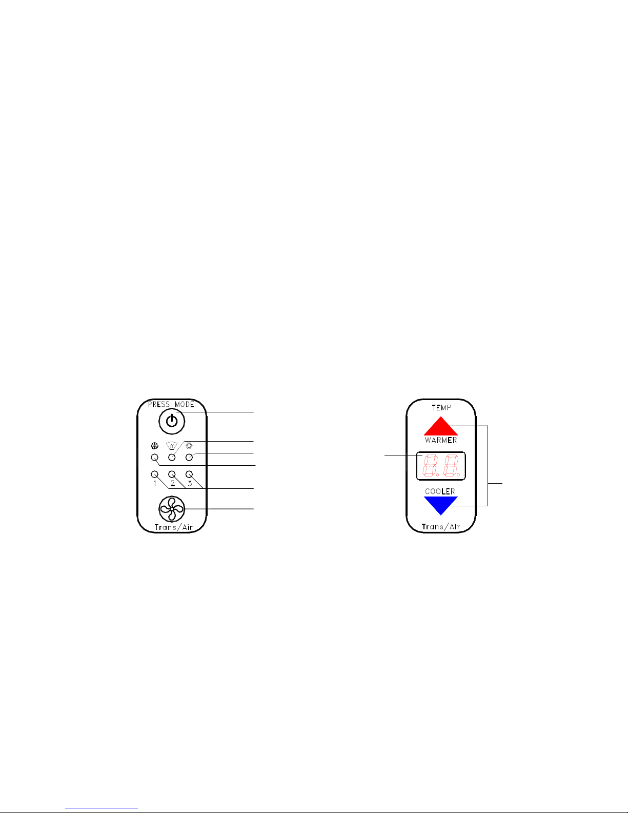
Switches
EC3.0 control switches: Mode switch (701426), Thermostat (701425).
ON/OF & MODE SELECT
A/C-DEFOG-HEAT-OFF
DEFOG
HEAT
A/C
FAN SPEED INDICATOR
FAN SPEED SELECT
AUTO-L-M-H-OFF
Figure 1 Control Switches
DISPLAY
SET POINT
ADJUST
Relay Board
The layout of an EC3.0 relay board is shown below. It has five relays, one 12 position
terminal block, three 10 amp fuses, two connectors and seven LED indicators. The function
of each component are listed in table below
EC3 Service Manual Jan. 8, 2008 1
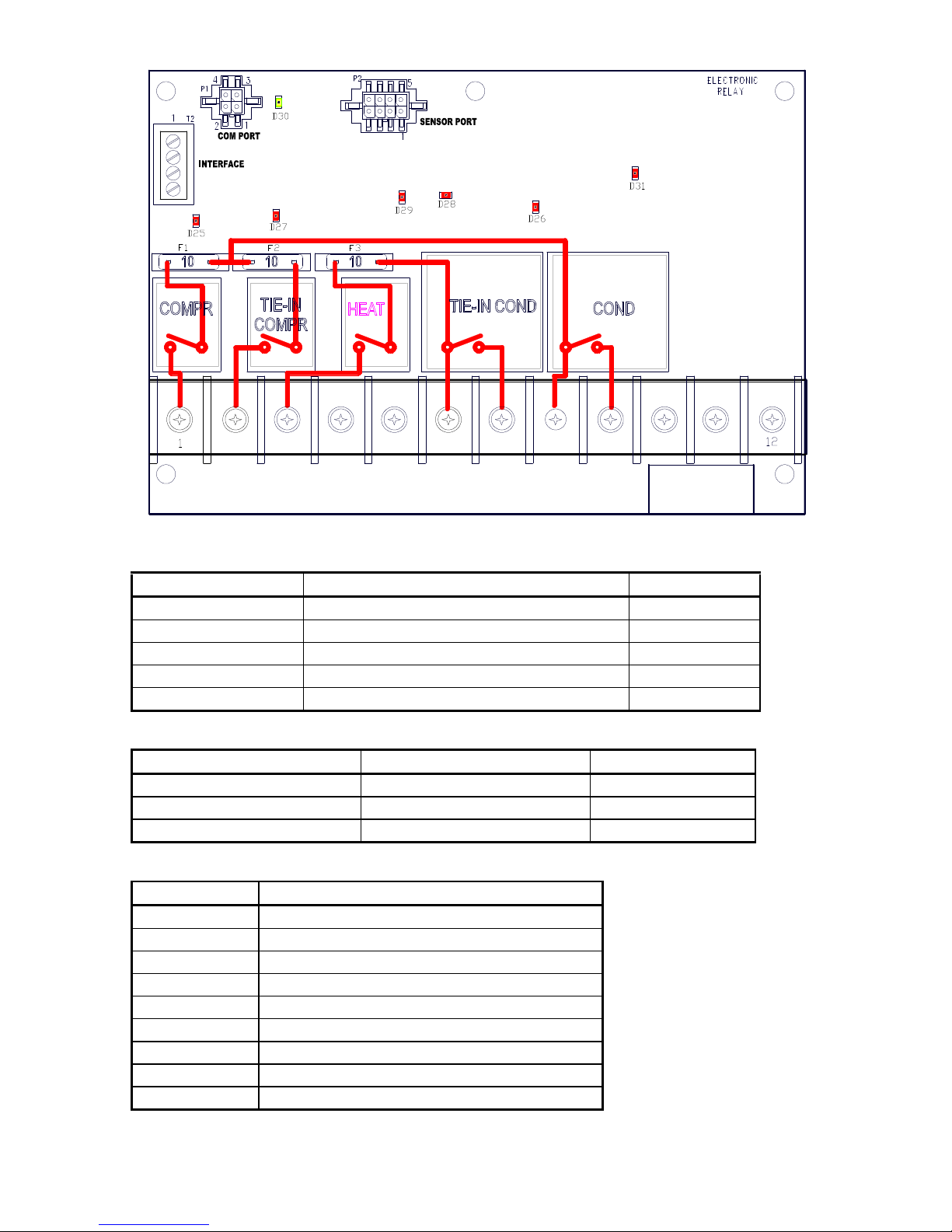
Figure 2 Relay Board Layout
Table 1 Relay Configuration
RELAY FUNCTION Currant rating
COMPR. Compressor clutch relay 10 amp
TIE-IN COMPR OEM tie-in compressor clutch relay 10 amp
HEAT Heat valve control relay 10 amp
TIE-IN COND. Tie-in condenser fan control relay 40 amp
COND. Condenser fan control relay 40 amp
Table 2 Fuse List
Fuse Description Rating
F1 Comp. Clutch fuse 10 amp
F2 Tie-in Comp. clutch fuse 10 amp
F3 Heat relay output fuse 10 amp
Table 3 Terminal Configuration
TERMINAL FUNCTION
1 Compressor clutch output
2 Tie-in compressor clutch output
3 Heat control relay output (optional)
4 Dash signal input
5 Ignition power input
6 Tie-in condenser power input
7 Tie-in compressor power output
8 Condenser power input
9 Condenser power output
EC3 Service Manual Jan. 8, 2008 2
 Loading...