

Page 1
GUIDE
POSjet® 1500
PROGRAMMER’S
PN: 20-03398
Rev M
Nov-2007
Page 2

Change Log POSjet® 1500 Programmer’s Guide
Change Log
Rev A Never Released
Rev B Nov 2001 Initial Release
Rev C Jan 2002
Rev D Nov 2002
Rev E Feb 2003
Rev F March 2003
Rev G October 2003
Rev H November 2005
Rev J March 2006
Rev K Feb 2007
Rev L Oct 2007
Rev M Nov 2007
1) Corrected the Auto Journal Documentation
2) Corrected the [ESC]f Quick Reference listing.
3) Fixed the OCR listing. (The wrong font was used to print this in some versions of the manual.)
4) Corrected some spelling errors.
5) Corrected the description of the EPOS Emulation [GS]0<Name…> <m> command
6) Added Page mode minimum size restrictions
7) Added more detail to several IPCL command descriptions.
8) Clarified the Epson [GS]k command
9) Added Journal features to the Epson [ESC]v command.
1) Corrected Pass through documentation.
2) Added Coupon-Cut-Logo feature.
1) Updated disclaimer
1) Fixed hex and decimal description of the [ESC][EM]L command
2) Removed ASB. It is now a special order option
1) Added slip detection documentation.
2) Added a validation right sensor operation modification command.
1) Added Las Vegas address
1) updated paper case p/n’s, descriptions & qtys
1) Pg 1 removed “buzzer” option
1) Corrected Electronic journal example.
2) Added support for periodic status back.
1) Added RoHS pat numbers for power cords in Appendix D
Page ii Rev M Nov-07
Page 3

Programmer’s Guide POSjet® 1500 General Information
POSjet® 1500
Disclaimer
© 2007 TransAct Technologies, Inc. All rights reserved.
NOTICE TO ALL PERSONS RECEIVING THIS DOCUMENT:
The information in this document is subject to change without notice. No part of this document may be reproduced,
stored or transmitted in any form or by any means, electronic or mechanical, for any purpose, without the express
written permission of TransAct Technologies, Inc. ("TransAct"). This document is the property of and contains
information that is both confidential and proprietary to TransAct. Recipient shall not disclose any portion of this
document to any third party.
TRANSACT DOES NOT ASSUME ANY LIABILITY FOR DAMAGES INCURRED, DIRECTLY OR
INDIRECTLY, FROM ANY ERRORS, OMISSIONS OR DISCREPANCIES IN THE INFORMATION
CONTAINED IN THIS DOCUMENT.
Some of the product names mentioned herein are used for identification purposes only and may be trademarks
and/or registered trademarks of their respective companies.
TransAct, PowerPocket, Magnetec, Insta-Load, POSjet, Ithaca, 50Plus and "Made to Order. Built to Last" are
registered trademarks and BANKjet is a trademark of TransAct Technologies, Inc.
Copyright
© 2001 - 2007 TransAct Technologies, Inc. All rights reserved.
Revision M, November 2007
Printed in USA.
Regulatory Compliance
North America:
EMI: FCC Class B
Safety: UL (US)
CUL (Canada)
Europe:
CE Marking: CLASS B: EN55022, EN50081-1 (optional)
Safety: TUV
Other: CB Certificate
Federal Communications Commission Radio Frequency Interference Statement
The POSjet® 1500 Printer complies with the limits for a Class A computing device in accordance with the
specifications in Part 15 of FCC rules. These regulations are designed to minimize radio frequency interference
during installation; however, there is no guarantee that radio or television interference will not occur during any
particular installation. Interference can be determined by turning the equipment off and on while the radio or
television is on. If the printer causes interference to radio or television reception, try to correct the interference by
one or more of the following measures:
•
Reorient the radio or television receiving antenna
•
Relocate the printer with respect to the receiver
•
Plug the printer and receiver into different circuits
If necessary, the user should consult their dealer or an experienced radio/television technician for additional
suggestions. The user may find the following booklet prepared by the Federal Communications Commission helpful:
How to Identify and Resolve Radio/TV Interference Problems. This booklet is available from the US Government
Printing Office, Washington, DC 20402. Ask for stock number 004-000-00345-4.
Nov-07 Rev M Page iii
Page 4

Change Log POSjet® 1500 Programmer’s Guide
Canadian Department of Communications Radio Interference Statement
The POSjet® 1500 Printer does not exceed Class A limits for radio noise emissions from digital apparatus set out in
the Radio Interference Regulations of the Canadian Department of Communications.
TransAct Technical Support
Monday through Friday, 8 A.M. to 8 P.M. Eastern Standard Time (excluding holidays). To obtain Technical
Support, call: TransAct at (607) 257-8901, or (877) 7-ITHACA.
Service Information
TransAct Technologies Incorporated has a full service organization to meet your printer service and repair
requirements. If your printer needs service, please contact your authorized printer service center. If any problems
still persist, you can directly contact TransAct at (607) 257-8901 or (877) 7-ITHACA for a return authorization.
International customers should contact your distributor for services. TransAct offers the following service programs
to meet your needs.
•
Extended Warranty
•
Depot Repair
•
Maintenance Contract
•
Internet Support
Please have the following information at hand:
1. The Model Number and Serial Number.
2. A list of any other peripheral devices attached to the same port as the printer.
3. The application software, operating system, and network you are using.
4. A copy of your printer’s Configuration Settings.
5. What happened and what you were doing when the problem occurred.
6. How you tried to solve the problem.
Warranty Information
TransAct’s POSjet® 1500 Printers come with a standard 24-month warranty that commences upon shipment from
factory, and covers parts and labor. An optional warranty, covering both parts and labor for an additional 12 months,
may be purchased separately. Repairs are warranted for 90 days from the date of repair or for the balance of the
original warranty period, which ever is greater.
Return Materials Authorization and Return Policies
If the technical support person determines that the printer should be serviced at our facility, and you want to return
the printer for repair, a Returned Materials Authorization (RMA) number must be issued before returning the
printer. Prepare the printer being returned for repair as follows:
1. Remove and discard ink cartridges.
2. Pack the printer to be returned in the original packing material. Packing items may be purchased from
TransAct's Ithaca Facility.
3. Return only the accessories that a Support Technician asks you to include.
4. Write the RMA number clearly on the outside of the box.
Shipping Printers
Never ship a printer by any means with any ink cartridge(s) installed.
packing materials in the event that you need to send the printer in for servicing. TransAct Technologies is not
responsible for damaged return items that are not packaged in original shipping material.
Be sure to save the
Page iv Rev M Nov-07
Page 5

Programmer’s Guide POSjet® 1500 General Information
Where Can You Find More Information?
Our Internet Support and Sales Services
www.transact-tech.com
TransAct Technologies Inc. maintains an Internet web site with content devoted to product support. Within the
Support Services section you can find the most current versions of the Operator’s Guide and Programmer’s Guide.
1. Upon entering our web site, you will be brought to the “Welcome to TransAct” screen. This intro page has the
Ithaca Brand listed at the top right. Click on the Ithaca logo.
2. Locate and click on the Technical Support button in the green area of the “Welcome to Ithaca” screen.
3. Use the bottom pulldown box to select the appropriate information for the printer model that you are using.
Contacting TransAct’s Ithaca Facility
Contact TransAct’s Ithaca facility for information about the POSjet® 1500 Printer and how it works with your
system. For information on international distribution, visit our web site at www.transact-tech.com. Contact the
TransAct’s Sales and Technical Support Departments at the following address and telephone or fax numbers.
Technical Support
Receive technical support, order documentation, request additional information, or send in a printer for service.
Sales
Order supplies, receive more product information, or order product brochures.
TransAct Technologies Incorporated
Ithaca Facility
20 Bomax Drive
Ithaca, NY 14850 USA
TransAct Technologies
World Gaming Headquarters
& Western Regional Repair Center
6700 Paradise Road
Suite D
Las Vegas, NV 89119 USA
Telephone (877) 7-ITHACA or (607) 257-8901
Main fax (607) 257-8922
Sales fax (607) 257-3868
Technical Support fax (607) 257-3911
Web site http://www.transact-tech.com
Nov-07 Rev M Page v
Page 6

Change Log POSjet® 1500 Programmer’s Guide
Table of Contents
POSJET® 1500 III
Disclaimer iii
Copyright iii
Regulatory Compliance iii
North America: iii
Europe: iii
Federal Communications Commission Radio Frequency Interference Statement iii
Canadian Department of Communications Radio Interference Statement iv
TransAct Technical Support iv
Service Information iv
Warranty Information iv
Return Materials Authorization and Return Policies iv
Shipping Printers iv
Where Can You Find More Information? v
Our Internet Support and Sales Services v
Contacting TransAct’s Ithaca Facility v
Technical Support v
Sales v
Table of Contents vi
Table of Tables xi
Table of Figures xiii
POSJET® 1500 FEATURES/SPECIFICATIONS 1
Standard Features 1
Optional Features 1
Additional Supported devices and tools 1
Drivers and Utilities Available 2
Optional Printer Configurations 2
Supported Emulations 2
Physical Printer Specifications 3
Auto-cutter (Partial Cut Option) 4
Sensors 4
Environmental Conditions 5
Relative Humidity 5
Reliability 5
Power and Communication Specifications 6
Power Requirements 6
Parallel Interface 6
RS-232 Serial Interface 7
USB Interface 8
Cash Drawer Interface Description and Specifics 9
Printing Specifications 10
Character Pitch 11
Graphics Generation 14
Media Specifications 15
Media Specifications 15
Receipt Paper (one-ply receipt) 15
Validation Form Requirements 16
Electrical Specifications 17
External Powered AC 17
Page vi Rev M Nov-07
Page 7

Programmer’s Guide POSjet® 1500 Table of Contents
External Powered DC 17
Cash Drawer 17
SETUP AND INSTALLATION PROCEDURES 17
Overview of Printer Controls 18
Leaving the 1500 Connected to a Power Source 18
Operating the Keypad Controls 18
Button Function Descriptions: 19
* Button 19
NEW CARTRIDGE Button 19
FEED Button 19
Form Button 19
Open Cover Button 20
Indicator Light Descriptions 20
Unpack the Printer 21
Connect Power and Communications 22
Installation Overview 22
Using the Cable Restraints 23
Connecting the Communication Cable 24
Connecting the Cash Drawer 25
Connecting the Cash Drawer 26
Connecting the Power Cord (with power supply) 27
Connecting the DC Power Cord (no power supply) 28
Paper Low Setup 29
Adjusting the Paper-Low Sensor 29
Paper Low Adjustment Requirements 30
Loading Ink Cartridges and Paper 31
Installing Ink Cartridges 31
Installing a New Paper Roll Using Insta-Load® 33
Printing the Configuration Summary Receipt 34
Placing the Printer In Self-Test Mode (printing the Configuration Summary Receipt) 34
Exiting Self-Test Mode 34
Matching Printer Configuration Settings to your System 34
Verifying the Printer Setup 35
Verify the communications interface card 35
Installing the new interface card 36
Verify the Cash Drawer Interface 36
Matching the Cash Drawer Interface 36
POSJET® 1500 OPERATION 38
Using Ink Cartridges 38
Care of Ink Cartridges 38
Determining Ink Cartridge Status 39
Validation Form Insertion and Orientation 40
Validation Orientation 40
Form Requirements 40
Inserting Validation Forms 41
Preventing and Clearing Validation Jams 42
Printer Self Testing and Diagnostics 43
Printer Self-Testing 43
Placing the Printer In Self-Test Mode 44
Exiting Self-Test Mode 44
Remote Power Down 44
Self-Test Hints and Suggestions 44
Nov-07 Rev M Page vii
Page 8

Change Log POSjet® 1500 Programmer’s Guide
Level 0 Diagnostics 45
Firmware Test 45
Boot Loader Mode 45
Extended Diagnostics 46
Self-Test Diagnostics 46
Hex-dump Mode 46
Configuration Mode 47
Configuration Mode 47
Remote Configuration Software 47
Manual Configuration 47
Using Self-Test to View Configuration Settings 48
Entering Configuration Mode 48
Making Changes in Configuration Mode 49
Configurable Features 50
Printer Color Configuration 58
Ink Cartridge Setup 58
COLOR PRINTING AND PRINT DRIVERS 60
Character Graphics 60
APA Graphics 61
Color Graphics 62
Procedure for color horizontal graphics: 63
PRINTER DRIVERS AND PRINTER CONTROLS 64
General Driver Information 64
Installing Windows® Printer Drivers (WIN95, 98, Me) 65
Printer Driver Installation Instructions for NT4.0, 2000 65
OPOS Drivers Installation Instructions 66
To Install the USB drivers 66
Configuring Windows® Printer Drivers (WIN95, 98, Me) 67
Configuring Ithaca OPOS Drivers 70
Printer driver 70
Printing 70
General Settings 71
Performance 71
Communications Port: 71
Paper Out: 72
Cash Drawer Dialog 72
Printing using a printer driver (Printer Font) 73
Printing via a printer driver (System/Graphical/TrueType Font) 74
Printing via an OPOS driver 77
Printing via POSPrinter OCX 81
TROUBLESHOOTING 82
Indicator Lights (LED) 82
The five POSjet® 1500 indicator lights are: 82
Power Indicator (LED) 82
Error Indicator (LED) 82
Paper Indicator (LED) 82
Form Indicator (LED) 82
Cartridge Indicators (LED-left and right) 82
Fault Indicators 82
Three types of faults exist 83
Recovery from Errors 83
Startup Troubleshooting 85
Page viii Rev M Nov-07
Page 9

Programmer’s Guide POSjet® 1500 Table of Contents
Operational Troubleshooting 86
Understanding Fault Indicators 86
Indicator Light Blink Patterns 86
Keypad Indicator Troubleshooting Chart: General Problems 87
Keypad Indicator Troubleshooting Chart: Serious Problems 87
Correcting Common Operating Problems 88
PROGRAMMING CONTROLS 90
Control Codes Overview 90
Nomenclature 90
Standard Emulation 91
IPCL Codes 91
EPOS Emulation 91
Ithaca® Microline Emulation 91
Application Development 91
Ithaca Control Codes and Commands 92
PcOS Printer Control Codes 92
Quick PcOS Reference Chart By Function 93
Vertical Motion 93
Character Pitch 93
Character Attributes 94
Electronic Journal 96
Quick PcOS Reference Chart (Alphabetic) 98
Low Level Paper Motion Control 102
Horizontal Motion Control 103
Vertical Motion Control 105
Character Pitch 110
Character Font 113
OCR Characters 122
Character Attribute Commands 123
Print Zone Control 127
Print Rotation Commands 128
POSjet 1500 Page Mode 131
POSjet® 1500 Graphics 140
User Store (Graphic Save) 145
Bar Codes 152
POSjet® 1500 Validation Operation 156
Electronic Journal 162
Miscellaneous Commands 173
Ithaca® Series 50 Compatibility Commands 189
ESC/POSTM Codes (EPOS) 194
Differences between Epson TM U325D and POSjet® 1500 194
Page Mode 195
Undocumented Epson Commands 195
Real-time Status 195
Supported TM-U325D Commands 196
Supported TM-U325D Commands 197
Undocumented TM-U325D Commands 198
Supported EPOS Commands 199
Supported EPOS Commands 201
Extended Electronic Journal Commands 202
TM-U325D and EPOS Command Descriptions 203
Nov-07 Rev M Page ix
Page 10

Change Log POSjet® 1500 Programmer’s Guide
Print and Feed Commands 203
Line Spacing Commands 205
Character Commands 205
International Character Sets 207
Panel Button Commands 213
Paper Sensor Commands 214
Print Position Commands 216
Bit-Image Commands 218
Status Commands 219
Printing Paper Command 223
Page Mode 225
Bar Code Commands 228
Mechanism Control Commands 230
Miscellaneous Commands 231
Macro Function Commands 234
User-defined Images and Graphics Commands 235
Ithaca® Specific POSjet® Commands 239
Panel Button Commands 239
Paper Out/Low Sensor Commands 239
POSJET® EXTENDED PRINTER CONTROL 240
POSJET® UNIVERSAL COLOR GRAPHICS 244
Print File Graphics 244
To generate a print file. 244
Store Graphics in the printer: 245
To Store a graphic in the printer 245
Print a stored graphic. 245
Generate a file to store graphics into a printer 245
How universal graphics is done 245
How to use IPCL commands in text strings 246
Load and store named graphic image 246
Recall and print stored named graphic image 246
Cautions 246
Universal Color Command Descriptions 247
POSjet® Coupon-Cut-Logo Feature 249
PORT PROTOCOLS AND CONNECTION SPECIFICS 250
Printer Flow Control and Print Buffers 250
Printer Buffer Size 253
Universal Serial Bus (USB) 253
USB Support and Standards 253
Parallel Port 255
Parallel Port Protocol 255
Parallel Port Timing 255
Parallel Port Inquire and IEEE 1284 257
Parallel Port Plug and Play 258
Serial Port 259
Serial Port Protocol 259
Page x Rev M Nov-07
Page 11

Programmer’s Guide POSjet® 1500 Table of Contents
Print Buffer Flow 261
Printer Buffer Size 263
Serial Mode Plug and Play 263
Using DSR 263
Serial Device Identification 263
Serial Port Inquire 264
Display Pass Through 265
Remote Power Control 265
Remote Printer Reset 266
Reset in Serial Mode 266
Reset in Parallel Mode 266
Miscellaneous Communication Features 267
Power-cycle Recovery 267
Data Pass Through 267
Multi-drop Configuration 267
Off line Active 267
APPENDIX A: COMMON OPERATIONAL QUESTIONS 268
APPENDIX B: ASCII CODE TABLE 269
APPENDIX C: DEFINITION TABLE 270
APPENDIX D: ORDERING SUPPLIES 272
Table of Tables
Table 1 Parallel Interface Pin-outs 6
Table 2 Serial Interface Pin Assignments 7
Table 3 Cash Drawer Connectors 9
Table 4 Print Speed Specifications 10
Table 5 Character Specifications 10
Table 6 Possible Character Pitches 11
Table 7 Basic Cell Size for Draft, Large Draft, and NLQ Fonts 12
Table 8 Ink Cartridge Maximum Operating Conditions 15
Table 9 Standard Power Input Requirements 17
Table 10 Power Input Requirements Optional 24-volt DC Supplied from Host 17
Table 11 Paper Low Setup 30
Table 12 Carriage Configurations 38
Table 13 Validation: Printer Settings and Requirements 40
Table 14 Extended Diagnostics 46
Table 15 How to Change Configuration Settings 49
Table 16 Configurable Options 57
Table 17 Single Color Printer-Color Configuration Details 58
Table 18 Two Color Ready Operation-Color Configuration Details 59
Table 19 Two Color Operation-Color Configuration Details 59
Table 20 Color Bits Received 62
Table 21 StartupTroubleshooting Help 85
Table 22 Keypad Indicators: General Problems 87
Table 23 Keypad Indicators: Serious Problems 87
Table 24 Troubleshooting: Keypad Lights Will Not Work 88
Table 25 Troubleshooting: Printer Will Not Print (Error Light ON) 88
Table 26 Troubleshooting: Printer Will Not Print (Error Light OFF) 88
Table 27 Troubleshooting: Printer Prints With Missing Dots in Characters 89
Table 28 Troubleshooting: Printer Sounds Like It’s Printing But Nothing Prints 89
Table 29 Troubleshooting: Printer Will Not Load or Feed Paper 89
Nov-07 Rev M Page xi
Page 12

Change Log POSjet® 1500 Programmer’s Guide
Table 30 Character Pitch 111
Table 31 Inter-character Spacing 112
Table 32 Language Table ID’s 115
Table 33 Code Page Definition Table 117
Table 34 Euro Character Substitution Matrix 118
Table 35 OCR MA-3 122
Table 36 Max/Min Page Mode Height, Width, and Offsets 132
Table 37 Validation Form Requirements and Print Area 156
Table 38 Paper Sensor Commands 175
Table 39 Paper Sensor Commands 176
Table 40 Supported TM-U325D Commands 197
Table 41 Undocumented TM-U325D Commands 198
Table 42 Supported EPOS Commands 199
Table 43 International Character Sets 207
Table 44 Character Code Pages 209
Table 45 Character Code Table 210
Table 46 Print Modes 211
Table 47 Rotation Modes 212
Table 48 Paper Sensor Commands 214
Table 49 Paper Sensor Commands 215
Table 50 Print Density Selection 218
Table 51 Paper Sensor Status (<n> = 1, 49) 219
Table 52 Drawer Kick-out Connector Status (<n> = 2, 50) 220
Table 53 Values for the Status Function, <n> 220
Table 54 Printer Status (<n> = 1) 220
Table 55 Off line Status (<n> = 2) 221
Table 56 Error Status (<n> = 3) 221
Table 57 Paper Roll Sensor Status (<n> = 4) 221
Table 58 Peripheral Status (<n> = 0, 48) 222
Table 59 Paper Status 222
Table 60 Bar Code System Based on <m> 228
Table 61 Printing Position of HRI Characters 229
Table 62 Font for Human Readable Interpretation (HRI) Characters 229
Table 63 Printer ID 231
Table 64 Type ID (<n> = 2or 50) 231
Table 65 Peripheral Device Bit Definitions 232
Table 66 Macro Control Bit Definitions 234
Table 67 User-defined Bit-image Resolutions 238
Table 68 Parallel-port Timing 256
Table 69 Common Operator’s Questions (FAQ’s) 268
Table 70 Paper Ordering Information 272
Table 71 Paper Ordering Information 272
Table 72 Ink Cartridge Ordering Information 272
Table 73 Cables Ordering Information 272
Page xii Rev M Nov-07
Page 13

Programmer’s Guide POSjet® 1500 Table of Contents
Table of Figures
Figure 1 Printer Dimensions 3
Figure 2 Receipt Printable Area 4
Figure 3 Environmental Conditions:Typical Operating Range 5
Figure 4 Cash Drawer Pin Assignments 9
Figure 5 Draft 12 x 12 Font 12
Figure 6 Large 12 x 14 Font 12
Figure 7 NLQ 24 x 16 Font 13
Figure 8 Paper Roll and Paper Core Diameters 15
Figure 9 Form Print Zones 16
Figure 10 Keypad Buttons and Indicator Lights 18
Figure 11 Unpacking Instructions 21
Figure 12 Power and Communications Connections 22
Figure 13 Using the Cable Restraints 23
Figure 14 Connecting Serial Cables 24
Figure 15 Connecting Parallel Cable 25
Figure 16 Connecting the Cash Drawer Cable 26
Figure 17 Connecting the AC Power Cord (with power supply) 27
Figure 18 Connecting the DC Power Cord (no power supply) 28
Figure 19 Paper Low Setup (adjusting the sensor) 29
Figure 21 Cash Drawer Selection 36
Figure 22 Cash Drawer Shunt 37
Figure 23 Example of Character Graphics 60
Figure 24 Example Commands for a Sample Receipt 60
Figure 25 Sample Receipt 61
Figure 26 Receipt with graphics 63
Figure 27 Page Definition 131
Figure 28 Page Mode entry Orientations 132
Figure 29 Validation Print Zone 157
Figure 30 Check Printing 157
Figure 31 Typical POS System 250
Figure 32 Host to Printer Link 251
Figure 33 Printer Communications Buffer Flow 252
Figure 34 Parallel-port Data Timing 255
Figure 35 Parallel Port ACK Timing Options 256
Figure 36 Serial Port Flow Control Using DTR 259
Figure 37 XON/XOFF Serial Port Flow Control 260
Nov-07 Rev M Page xiii
Page 14

Page 15

Programmer’s Guide POSjet® 1500 Features/Specifications
POSjet® 1500 Features/Specifications
Standard Features
•
Print Speed: 12 lps. at 10 char. per line
•
Print Resolution: Max. 208 dpi. Horizontal, 96 dpi. Vertical
•
Simple Snap-In, No-Mess Cartridges with Fast-Drying Ink
•
Standard Warranty: Two Years (Extended Maintenance Plan Available)
•
Patented Insta-Load® Automatic Paper Loading
•
Cash Drawer Drivers: Dual with Status (Single RJ12)
•
Font Selections: Draft, Large Draft and Near Letter Quality
•
Selectable Printing Features of Bold, Italics, Size Scaling and Rotated
•
Emulations: Ithaca/IBM, Epson ESC/POS, and TM-U325, Ithaca M50, and Microline
•
APA and Epson Bit Map Graphics
•
Data Buffer: 8K (Adjustable)
•
208K Non-Volatile Flash for Multiple Character Sets, Bit Images and Electronic Journal
•
Bar Codes: Code 39, Code 93, Interleaved 2 of 5, UPC-A and UPC-E, EAN8 and EAN13, Code 128
•
65 Language Character Sets Supported (EURO Character Included)
•
Self Diagnostics
•
Remote Statistics
•
Paper Out and Ink Low Detection and Indicators
•
Software Developer’s Toolkit Available
•
Top Drop-in Forms Insertion with Programmable Top of Form
•
Independent Validation
Optional Features
•
Auto-cutter (partial cut)
•
Adjustable paper low
•
Two-Color Printing
•
Universal Power Supply and PowerPocket®
Additional Supported devices and tools
Printer Test and Configuration Programs
The POSjet® 1500 will be supported by various PC based tools. These tools include, but are not limited to the
following:
PJColor
PJColor is a program that will allow images and picture to be processed so they can work with the printer.
PJTerminal
PJTerminal is a test application that is used to verify communications to the printer.
PJBootload
PJBootload is a program that is used to replace or update the printer’s firmware.
Ithaca Config
Ithaca Config is a program that is used to replace or update the printer’s configuration settings.
Nov-07 Rev M Page 1
Page 16

Features/Specifications POSjet® 1500 Programmer’s Guide
Drivers and Utilities Available
POSjet® 1500 Drivers and Utilities can be downloaded from our web site, or call our Technical Support Department
to request a Software Developer’s Toolkit (CD-ROM).
POSjet Image Converter Utility
POSjet Image Converter (PJColor) is a tool to help develop graphic images to use as logos and coupons on the
printer. It will read and convert images to a format suitable for printing on the POSjet® 1500 printer. It will allow
you to preview the image and adjust the colors prior to printing. It will also allow the images to be stored in the
printer's User Store.
PJTerminal Utility
PJTerminal is a tool that has been developed to allow you to interactively send commands to and get responses from
the printer.
Optional Printer Configurations
Color Configuration
All POSjet® 1500 ink cartridge configurations are factory installed options.
Single Color
The single color configuration is provided with a single ink cartridge. It cannot be upgraded for two-color operation.
Two-Color Ready
The two color ready configuration is equipped with a single ink cartridge but can be easily upgraded to two-color
operation simply by installing a second ink cartridge.
Two-Color
Two-color configuration requires that two cartridges be installed in the carriage. If one of the cartridges is black, it
must be installed in the left carriage position.
Supported Emulations
Ithaca PcOS
The Ithaca Standard emulation is the Ithaca PcOS emulation with extensions that provide full support for the
POSjet® 1500 features. This emulation is similar to the IBM control codes used in a number of IBM printers.
TM-U325
The TM-U325 emulation is intended to allow the POSjet® 1500 to replace the TM-U325 printer with no changes to
the host application.
Epson ESC/POS®
The Epson ESC/POS® emulation provides support for features in the POSjet® 1500 printer that are not supported in
the TM-U325 emulation. POSjet® 1500 follows the Epson ESC/POS specification as close as possible.
Ithaca M50 andIthaca® Microline
The POSjet® 1500 provides M50 and M50 Microline emulations to allow older Model 50 printers to be replaced
with minimal changes to the host application.
®
Page 2 Rev M Nov-07
Page 17
Programmer’s Guide POSjet® 1500 Features/Specifications
Physical Printer Specifications
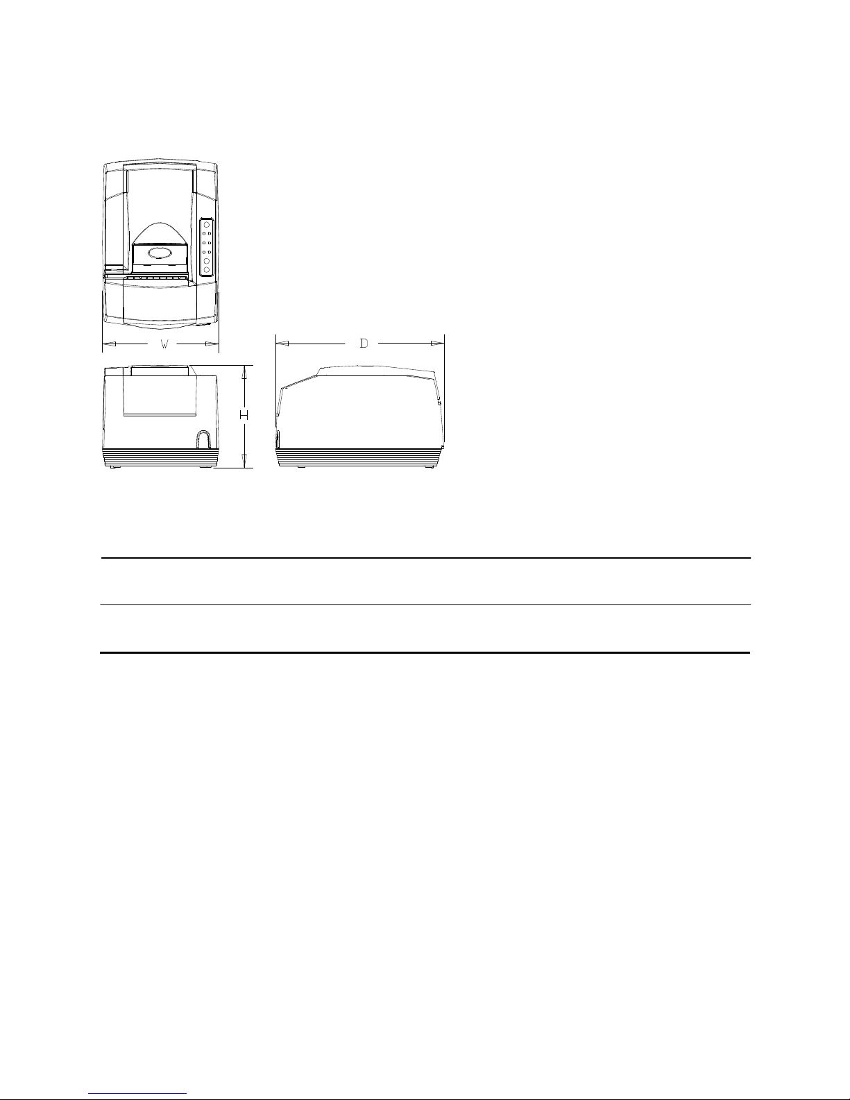
Figure 1 Printer Dimensions
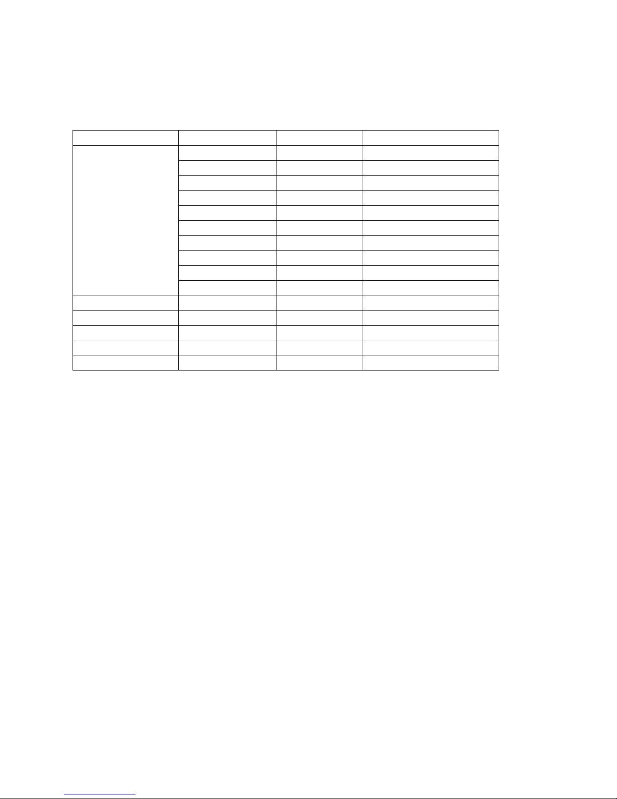
Width Depth Height
Without Knife 6.75" 9.75" 5.92"
(172 mm) (248 mm) (151 mm)
With Knife 6.75" 9.75" 6.44"
(172 mm) (248 mm) (164 mm)
Weight: approx. 6 lbs. (2.7 kg)
Shipping: approx. 8 lbs. (3.6 kg)
Interface
Serial RS-232C Bi-directional- Ready/Busy or XON/XOFF (9-pin D-shell or 25-pin D-shell)
Parallel IEEE1284 Bi-directional-transmit/receive/ground (25-pin D-shell or 36-pin Centronics)
USB Version 1.1
Nov-07 Rev M Page 3
Page 18
Features/Specifications POSjet® 1500 Programmer’s Guide
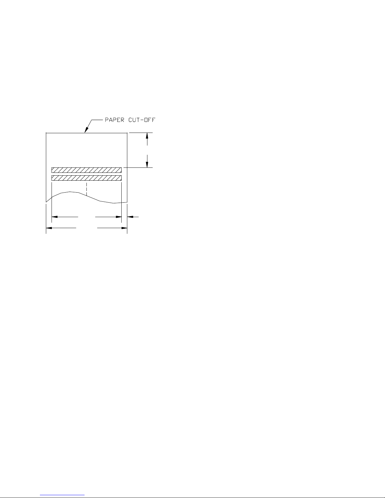
Auto-cutter (Partial Cut Option)
A receipt auto-cutter is an optional feature with all POSjet® 1500 Printers.
Cutter type Guillotine
Cut to line of print 1.635" (41.52 mm)
Cutter life 1,000,000 cuts
Auto-cutter Position
1.635"
0.25
2.5
3.0
"
"
"
Figure 2 Receipt Printable Area
Sensors
Paper low indicator Optional Paper Low Sensor (based on paper roll diameter).
Receipt paper out About 1.0" (25 mm) of paper remaining
Paper feed method Friction feed
Paper Out
A receipt paper out sensor is provided as a standard feature. It senses when there is approximately one inch of paper
left on the paper roll.
Paper Low
A receipt paper-low sensor is provided as an optional feature. An operator-adjustable paper-low assembly allows
the printer to sense when the paper roll is between 1.42" and 0.885" (36.1mm and 22.5mm) in diameter. It is
adjustable to compensate for various paper core dimensions.
Page 4 Rev M Nov-07
Page 19
Programmer’s Guide POSjet® 1500 Features/Specifications
Environmental Conditions
The POSjet® 1500 is designed to be placed on point-of-sale terminals, counter tops, or any other flat, stable surface
that can support the weight of the printer (about 6 lbs. or 2.7 kg). Be aware that the environmental conditions of the
location where you place the printer will have an effect on the printer’s performance and longevity. The printer will
run its best when stored and operated in an environment that meets the following temperature and humidity
conditions.
90%
80%
70%
60%
Relative Humidity
50%
40%
30%
Extended Operating
Range
Typical
Operating
Range
20%
10%
5%
Shipping
5 0 -40 10 15 20 25 30 35 40 60 70 -10
Figure 3 Environmental Conditions:Typical Operating Range
Typical Operating Range: 10°C to 40°C / 50°F to 104°F
*Extended Operating Range: 0°C to 45°C / 32°F to 113°F+
Storage: -10°C to 60°C / 14°F to 140°F
Shipping: -40°C to 70°C / -40°F to 158°F
* Exposure to high or low temperatures for periods of greater than 48 hours will lead to significantly reduced cartridge life. The Typical Operating Range provides full printer reliability. The
Extended Operating Range may degrade the reliability of the printer and life of the cartridge.
Temperature (°C)
Storage
45
Relative Humidity
Operating: 10% to 90% RH (non-condensing)
Storage: 10% to 90% RH (non-condensing)
Shipping: 5% to 90% RH (non-condensing)
Reliability
Printer Life 10,000,000 print lines
Mean time between failures: (without cartridge): 28,000 hours
Average cartridge life (Average 16 dots/character): 7.0 million characters
Auto-cutter option (partial cut) : 1 million cuts
Mean time to repair: 15 minutes
Validation Cycles : 1 million cycles
Nov-07 Rev M Page 5
Page 20
Features/Specifications POSjet® 1500 Programmer’s Guide
Power and Communication Specifications
Power Requirements
Earth Ground
+24 Volt Supply
DC Powered Versions
Ground (+24 V dc)
Supply voltage: 24 Vdc ± 10%
Supply Current: 1.0Amps
AC Powered Versions
Supply Voltage: 100-240 Vac
Frequency: 50/60 Hz
Supply Current: .5 Amps maximum
Parallel Interface
There are two parallel interface cards available. One is a 25-pin, D-shell connector. The pin-out is such that the
printer interfaces to a standard IBM PC parallel printer interface with a one-to-one cable. The second interface card
provides the same interface with a standard, 36-pin Centronics type connector. Both cards provide a dual cash
drawer interface. The tables below lists interface signals and pin definitions for both types of parallel interfaces.
25-pin D-Shell IEEE 1284-A
36-pin Centronics IEEE 1284-B
Parallel Pin Assignments
25-pin Connector 36-pin Connector Signal Description Direction
Pin 1 Pin 1 STROBE Clock data to printer Host to Printer
Pins 2-9 Pins 2-9 D0 - D7 Data Host to Printer
Pin 10 Pin 10 ACK\ Printer accepted data Printer to Host
Pin 11 Pin 11 BUSY Printer busy Printer to Host
Pin 12 Pin 12 PE Paper Out/Status Printer to Host
Pin 13 Pin 13 SLCT Printer selected Printer to Host
Pin 14 Pin 14 AUTOFD Autofeed paper Host to Printer
Pin 15 Pin 32 FAULT\ Printer error Printer to Host
Pin 16 Pin 31 INIT\ Initialize printer Host to Printer
Pin 17 Pin 36 SLIN Select printer Host to Printer
Pin 17 FG Frame ground Printer to Host
- Pin 18 +5V Peripheral logic high Printer to Host
Pins 18-25 Pins 16, 19-30 GND Ground
Table 1 Parallel Interface Pin-outs
Page 6 Rev M Nov-07
Page 21
Programmer’s Guide POSjet® 1500 Features/Specifications
Parallel Signal Voltage and Current levels
Signal Levels
Voltage levels 0 V and +5 V (nominal)
Logic levels
Logic one Driver +2.4 V to +5 V
Receiver +2.0 V to +5 V
Logic zero Driver 0 V to +0.4 V
Receiver 0 V to +0.8 V
Current requirements
Logic one Source 0.25 ma at +2.4 V
Logic zero Sink 16 ma
Line termination
Data and control 3.3k ohm to +5 V
Strobe 1.2k ohm to +5 V
RS-232 Serial Interface
There are two serial interface cards available. One is a 9-pin, D-shell connector. The pin-out is such that the printer
interfaces to a standard IBM PC Serial printer interface with a Serial Null Modem cable. The second interface card
provides the same interface with a standard 25-pin D-shell connector. Both interface cards provide a dual cash
drawer interface. The tables below lists interface signals and pin definitions for both types of serial interfaces.
Serial Port Features
Baud Rates
Bit Patterns
Flow Control
300, 600, 1200, 2400, 4800, 9600, 19.2K, 38.4K, and 57.6K
8-bit no parity; 8-bit odd; 8-bit even; 7-bit no parity; 7-bit odd; 7-bit even
DTR and XON/XOFF
Serial Pin Assignments
9-pin 25-pin Signal Description
Pin 1 Pin 8 N/C No Connection
Pin 2 Pin 3 RX Receive Data
Pin 3 Pin 2 TX Transmit Data
Pin 4 Pin 20 DTR Data Terminal Ready
Pin 5 Pin 7 GND Signal Ground
Pin 6 Pin 6 DSR Data Set Ready
Pin 7 Pin 4 RTS Request to Send
Pin 8 Pin 5 CTS Clear to Send
Pin 9 Pin 11 N/C No Connection
Table 2 Serial Interface Pin Assignments
Nov-07 Rev M Page 7
Page 22

Features/Specifications POSjet® 1500 Programmer’s Guide
RS-232 Serial Interface Signal Voltage and Current levels
Voltage Levels Max +-15 Volts
Min +- 3 Volts
Mark = Off = -3 to –15 Volts
Space = On = +3 to +15 Volts
Because both the host and printer are DTE's (Data Terminal Equipment), they use the same serial port pin-outs. If
the cable that is used to connect the host to the printer is a pin-to-pin inter-connect, it will not work. Therefore, a
null modem or turn-around cable must be used to interconnect the host and the printer.
Display Pass Through
The display pass through feature allows a pole display to be interconnected with the printer. The printer is
connected to a host system with a special serial cable. The host sends serial data to the printer and the printer sends
serial data to the pole display. The printer does not provide power to the display. During normal printer operation,
no data is passed to the display. In pass through mode, all received data is passed on to the display.
USB Interface
The USB interface is a Version 1.1 interface that is Version 2.0 compliant. The standard USB interface card is
implemented through a Standard Series "B" Receptacle as defined in the USB Specification. The printer is selfpowered and does not draw power from the standard type B USB interface cable.
The Standard USB Type B connector has the following pin functions:
Pin Signal
1 Vbus (+5 V dc) (Not used in the POSjet® 1500)
2 Minus data
3 Plus data
4 Ground
Note: The standard USB interface does not have enough power to run the printer.
Page 8 Rev M Nov-07
Page 23

Programmer’s Guide POSjet® 1500 Features/Specifications
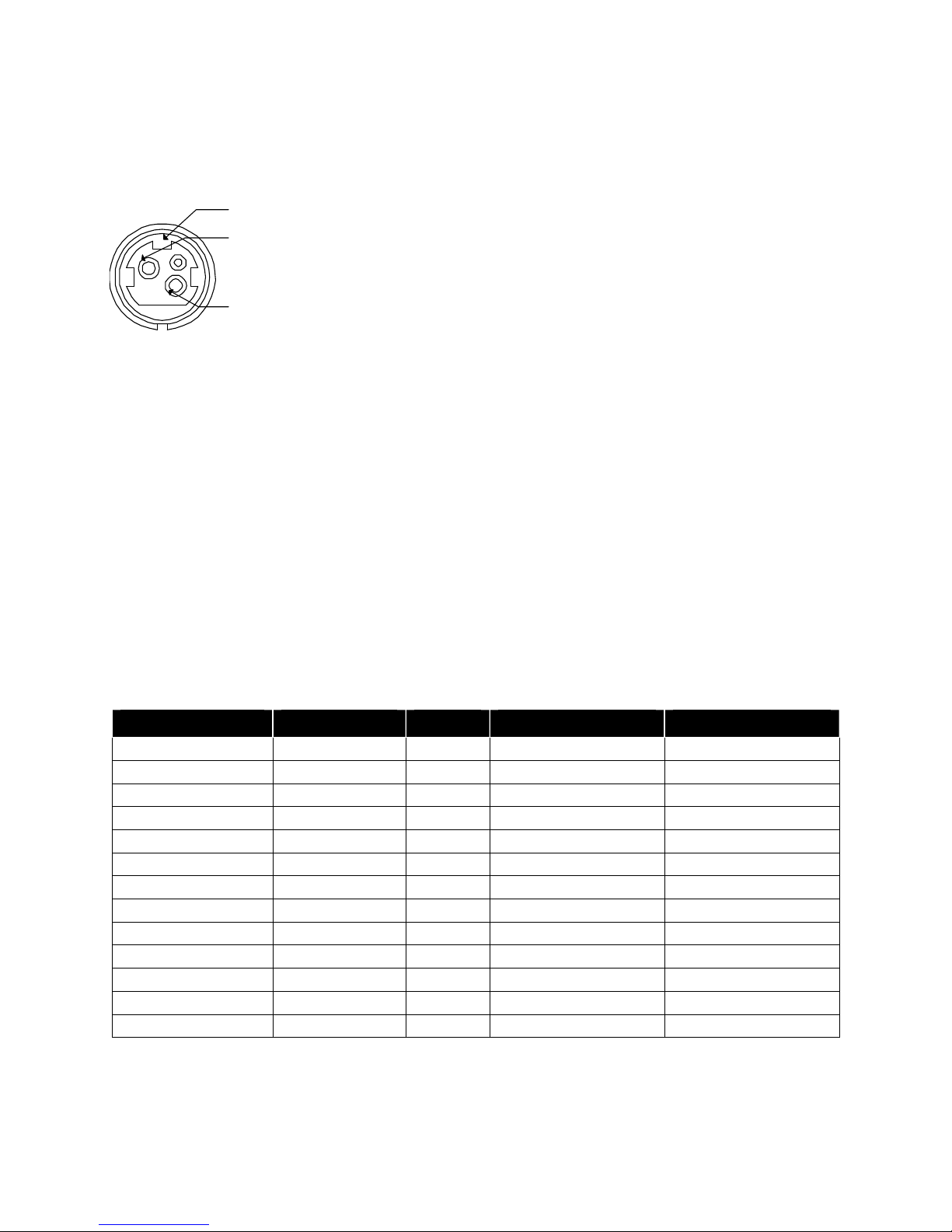
Cash Drawer Interface Description and Specifics
The POSjet® 1500 Printer supports dual cash drawers with status. The driver in the printer is capable of supplying
24 Vdc at up to 1.5 amps for 250 milliseconds. The POSjet® 1500 Printer defines cash drawer closed as switch open.
If the drawer is disconnected, the printer considers it closed. Since the printer does not act on the cash drawer status,
the application can interpret cash drawer status in a variable manner.
Connector Type (standard) Single RJ12 connector with 24V sink drivers
Voltage 24 volts (Refer to power supply specification)
Current 1 amp maximum with current limit
Pulse Duration 250 msec maximum
Drawer Status Open/close drawer status to printer
Ithaca® Epson Star
Signal Name
pin 1 CD2-
pin 2 CD1 Sense
pin 3 Ground
Pin Number
pin 4 CD Drive +(+24V)
pin 5 CD1-
pin 6 Not Connected
1
2 Drawer open/close Signal Input Drawer kick out 1 Drive
3 Signal Ground Drawer open/close Signal Input +24V DC
4 +24V DC +24V DC +24V DC
5 Drawer kick-out 1 Drive
6 Not Connected Signal Ground Drawer open/close Signal Input
Drawer kick out 2 Drive
Signal
Signal
Direction
Output
Sink
Drive
Output
Sink
Drive
Signal Name
pin 1 No Connect
pin 2 CD1-
pin 3 CD Drive + (+24V)
pin 4 CD Drive + (+24V)
pin 5 CD2-
pin 6 CD1 Sense
Not Connected Not Connected
Signal
Drawer kick out 2 Drive
Signal
Direction
Output
Sink
Drive
Output
Sink
Drive
Signal Name
pin 1 No Connect
pin 2 CD1-
pin 3 CD1 Sense
pin 4 CD Drive +(+24V)
pin 5 CD2-
pin 6 Ground
Drawer kick out 1 Drive
Signal
Drawer kick out 2 Drive
Signal
Direction
Output
Sink
Drive
Output
Sink
Drive
Table 3 Cash Drawer Connectors
The printer can be configured for one of three cash drawer configurations. The interface card has a 14-pin header
with a 10-pin shunt installed. The shunt position defines the configuration of the cash drawer. Refer to the markings
on the board when determining where the shunt should be installed to work in the three different configurations.
Epson
Pin 1 Pin 1 Pin 1
Nov-07 Rev M Page 9
Star Ithaca
Figure 4 Cash Drawer Pin Assignments
Page 24
Features/Specifications POSjet® 1500 Programmer’s Guide
Printing Specifications
Printing method: Thermal ink jet
Cartridge arrangement: 12 nozzle
Print dot pitch: 0.0096" (0.244 mm)
Printing directions: Bi-directional, logic seeking
Paper feed pitch: Default - 0.125" (1/8" or 3.175 mm)
Validation Type: Independent
Number of Validation lines: Max. 9 lines (1.53") @ 6 lpi. 12 lines @ 8 lpi.
Receipt print zone (maximum): 2.5" (63.5 mm)
Validation print zone: Refer to “Validation Form Requirements” on pg. 16.
Characters per Line Minimum Lines per Second1
10 12
20 10
30 8
40 6
Table 4 Print Speed Specifications
Print Pitch Capability
(Characters per Inch)
Font Half Wide
(Max CPI)
Max Characters/Line
Approximate
(2.5-inch Print Zone)
Single-
wide (Max
Double-
wide
Max Typ Dbl-wide
per Second
CPI)
Table 5 Character Specifications
Characters
1
Print speed is calculated with the 12 x 12 single wide font at 17.3 cpi and 8 lpi spacing. If head maintenance
needs to be done, the print speed will be less.
2
The value is based on a single full 2.5" print line printing single width, small draft font. Line feed time is not
included.
Page 10 Rev M Nov-07
Page 25
Programmer’s Guide POSjet® 1500 Features/Specifications
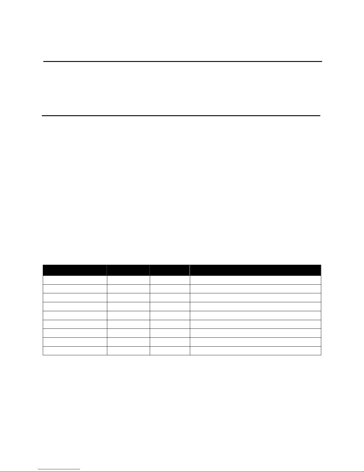
Character Pitch
Each character has at least one, half-column, inter-character spacing included within the cell size. The intercharacter spacing provides the maximum character pitch as shown in the table below. Change the spacing between
characters in one of two ways. The first is to request that right side spacing be added between characters; the other
is to request a specific pitch in characters per inch. When a specific character per inch (cpi) is selected, the printer
calculates the number of half dot columns that must be inserted or removed between characters to print at the
requested cpi. If the single width characters will overlap excessively, the printer will switch to half width characters.
It is not always possible to print at exactly the requested pitch. The printer selects the closest possible pitch to the
one chosen.
Result
ed CPI
NLQ
24 x 16 Font
1 1.000 CPI Std Font Std Font Std Font
2 2.000 CPI Std Font Std Font Std Font
3 3.014 CPI Std Font Std Font Std Font
4 4.000 CPI Std Font Std Font Std Font
5 4.952 CPI Std Font Std Font Std Font
6 5.943 CPI Std Font Std Font Std Font
7 6.933 CPI Std Font Std Font Std Font
8 8.000 CPI Std Font Std Font Std Font
9 9.043 CPI Std Font Std Font Std Font
10 9.905 CPI Std Font Std Font Std Font
11 10.947 CPI Std Font Std Font Std Font
12 12.235 CPI Std Font Std Font Std Font
13 13.000 CPI Std Font Std Font Std Font
14 13.867 CPI Std Font Std Font Std Font
15 14.857 CPI Std Font Std Font Std Font
16 16.000 CPI Std Font Std Font Std Font
17 17.333 CPI Not recommended Std Font Std Font
18 17.333 CPI Not recommended Std Font Std Font
19 18.909 CPI Not recommended Std Font Half Width
20 20.8 CPI Not recommended Half Width Half Width
21 20.8 CPI Not recommended Half Width Half Width
22 23.111 CPI Not recommended Half Width Half Width
23 23.111 CPI Not recommended Half Width Half Width
24 23.111 CPI Not recommended Half Width Half Width
25 23.111 CPI Not recommended Half Width Half Width
26 26.000 CPI Not recommended Half Width Half Width
27 26.000 CPI Not recommended Half Width Half Width
28 26.000 CPI Not recommended Half Width Half Width
29 29.714 CPI Not recommended Half Width Half Width
30 29.714 CPI Not recommended Half Width Half Width
31 29.714 CPI Not recommended Half Width Half Width
Table 6 Possible Character Pitches
Font Format Request
Small Draft
12 x 12 Font
Large Draft
12 x 14 Font
Nov-07 Rev M Page 11
Page 26

Features/Specifications POSjet® 1500 Programmer’s Guide
Standard Print
The three resident fonts in the printer are Draft, Large Draft, and Near Letter Quality (NLQ). The cell size for each
is different. In addition, the Small and Large Draft fonts can be printed in Double, Single and Half wide versions.
All width variations are based on a single width, and use mathematical algorithms to convert them to different
widths. The following discussion is based on the basic, single width character.
Character Cell Draft Large Draft NLQ
Horizontal 12 14 16
Vertical 12 12 24
Table 7 Basic Cell Size for Draft, Large Draft, and NLQ Fonts
Draft Font
The draft font is defined in the 12 x 12 cell to use 6 full-columns and 5 half-columns horizontally. In general, most
characters are only nine dots wide; however, to provide readable international characters, the minimum cell size is
kept at 12. The minimum cell size provides at least 1 half-column between any character.
The vertical format never uses the top dot, and the bottom 2 dots are used for character decenders and underline.
The draft font provides the most print per line and the most efficient use of ink per character.
01 ............
02 ....0.0.....
03 ...0...0....
04 ..0.....0...
05 .0.......0..
06 .0.0.0.0.0..
07 .0.......0..
08 .0.......0..
09 .0.......0..
10 .0.......0..
11 ............
12 ............
Figure 5 Draft 12 x 12 Font
Large Draft Font
The large draft font is defined in the 12 x 14 cell to use 7 full, and 6 half-columns horizontally, which provides at
least 1 half-column between any character.
The vertical format uses the first 10 rows for the characters and the bottom 2 for character decenders and underline.
The large draft font is larger than the draft font and is more readable. It, however, provides fewer characters per line
and uses more ink per character.
01 .....0.0......
02 ....0...0.....
03 ....0...0.....
04 ...0.....0....
05 ..0.......0...
06 ..0.......0...
07 .0.0.0.0.0.0..
08 .0.........0..
09 0...........0.
10 0...........0.
11 ..............
12 ..............
Figure 6 Large 12 x 14 Font
Page 12 Rev M Nov-07
Page 27

Programmer’s Guide POSjet® 1500 Features/Specifications
Near Letter Quality (NLQ) Font
The near letter quality font is defined in the 24 x 16 cell that is printed in 2 passes. Horizontally, 15 dots are
typically used, providing at least 1 half-column between any two characters.
The vertical format uses rows 4 - 19 for the basic character, rows 1 - 3 for accents, and rows 20 - 24 for decenders
and underlines. Because NLQ font makes two passes, the vertical size is slightly larger than large draft font.
Vertical resolution is doubled.
NLQ font is easily readable and has a higher contrast than the draft or large draft fonts. It, however, provides fewer
characters per line and uses more ink per character than either draft font.
In non-Ithaca® emulation modes, only the draft and large draft fonts are available. They provide a close
approximation to the Epson 9 x 9 and 7 x 9 formats available in the TM-U325 model printer.
01 ................
02 ................
03 ................
04 .......0........
05 .......0........
06 ......0.0.......
07 .....0...0......
08 .....0...0......
09 ....0.....0.....
10 ....0.....0.....
11 ....0.....0.....
12 ...0.......0....
13 ...0.......0....
14 ..00000000000...
15 ..0.........0...
16 ..0.........0...
17 .0...........0..
18 .0...........0..
19 0000.......0000.
20 ................
21 ................
22 ................
23 ................
24 ................
Figure 7 NLQ 24 x 16 Font
Rotated Print
To provide printing flexibility, rotated print is available. Rotated print mode rotates the print in any
of three 90° orientations. In 90° and 270° rotated mode, the print data is first buffered by the printer, processed
(rotated), and then printed. Buffering the data delays the print process as it takes some time
to process the data before it is printed. In 180° mode, the print is simply inverted. Rotated print is not available for
NLQ font or when the printer is in Epson mode.
Nov-07 Rev M Page 13
Page 28
Features/Specifications POSjet® 1500 Programmer’s Guide
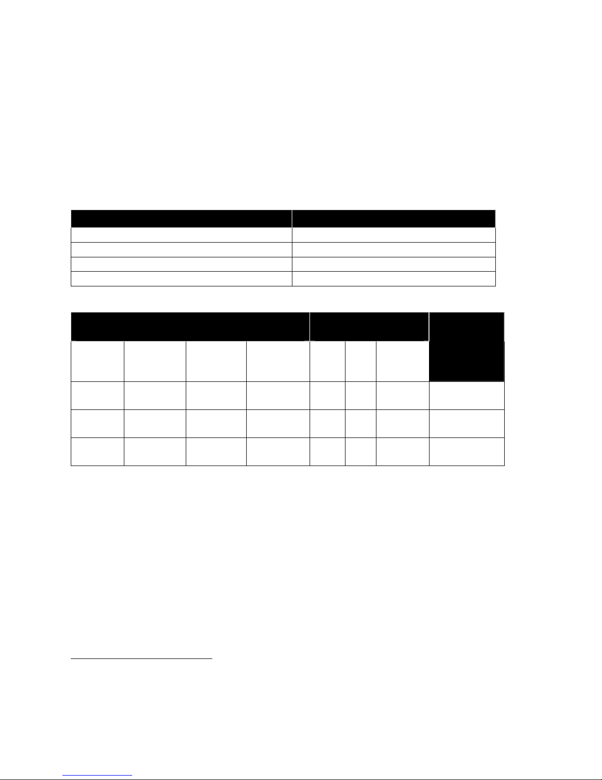
Graphics Generation
The POSjet® 1500 supports both APA graphics and color raster graphics (Horizontal graphics). In APA graphics
mode the following print resolutions are supported.
Mode Horizontal Vertical Data
APA graphics
NOTE: Not all
resolutions are
available in all
emulations.
208 dpi 240 24-bit slices
Horizontal graphics 104 dpi 96 dpi 1 horizontal 1 vertical pass
208 dpi 96 dpi 2 horizontal 1 vertical pass
104 dpi 192 dpi 1 horizontal 2 vertical passes
208 dpi 192 dpi 2 horizontal 2 vertical passes
* These horizontal resolutions are converted by scaling in the printer. They are printed in 104 or 208 dpi resolution.
Color graphics are supported in Horizontal graphics mode only.
60 dpi * 96 8-bit slices
120 dpi * 96 8-bit slices
120 dpi * 192 8-bit slices
240 dpi * 192 8-bit slices
80 dpi * 96 8-bit slices
72 dpi * 96 8-bit slices
90 dpi * 96 8-bit slices
144 dpi * 96 8-bit slices
160 dpi * 96 8-bit slices
104 dpi 120 24-bit slices
Page 14 Rev M Nov-07
Page 29
Programmer’s Guide POSjet® 1500 Features/Specifications
Media Specifications
Media Specifications
Hewlett-Packard Inkjet Cartridges
Print cartridge specification: HP C6602A3
Cartridge arrangement: 12 vertical nozzles
Vertical dot pitch: 0.264 mm (0.0104") or 96dpi.
Cartridge life: ~7.0 M Characters @ 16 dots per Character.
Cartridge colors: Black, Red, Blue, Green
Ink Cartridge Operating Conditions (maximum ratings)
Parameter Maximum Conditions
Shelf Life [1] 24 Months At 73°F / 9°C in shipping package
Out of Package Life [1] (Installed in Printer) 6 Months At 73°F / 9°C outside shipping package
Table 8 Ink Cartridge Maximum Operating Conditions
Note 1: Total life is Shelf Life (from date of manufacture) plus Out of Package Life.
Exposure to high and low temperatures, or long exposure times near specification limits, significantly
reduce cartridge life. Higher character capacities are achieved by reducing font resolution.
Receipt Paper (one-ply receipt)
Paper width: 3.0" ± .02" (76mm ± .5mm)
Paper roll diameter: 4.0" max (101.6mm max)
Paper thickness: .003" - .004" (.07mm - .1mm)
Roll paper core outside Dia.: 0.82" - 0.85" (20.8 – 21.6 mm) Dia.
Roll paper core inside Dia.: 0.45" - 0.50" (11.4 – 12.7 mm) Dia.
Roll footage: 330 feet standard grade
300 feet premium grade
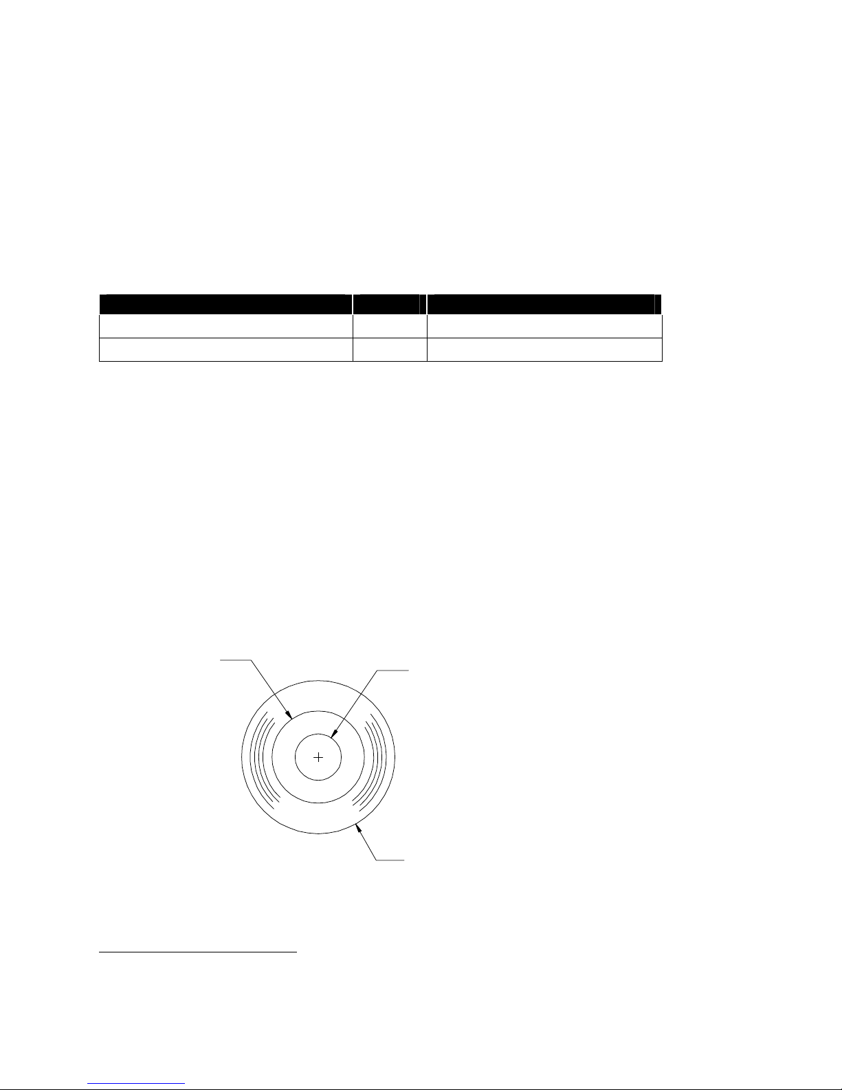
Paper and Core Diameter
To insure proper paper low detection, use paper rolls and paper that meet the specifications above. Adjustment and
operational results may vary if other thickness and width dimensions are used.
Outside Core Dia.
.82" to .85"
(20.8mm to 21.6mm)
Figure 8 Paper Roll and Paper Core Diameters
3
Print Cartridge Specifications are controlled by Hewlett-Packard and are proprietary. Information here is for
reference only.
Inside Core Dia.
.45" to .50"
(11.4mm to 12.7mm)
Refer to Paper Roll Diameter.
Nov-07 Rev M Page 15
Page 30
Features/Specifications POSjet® 1500 Programmer’s Guide
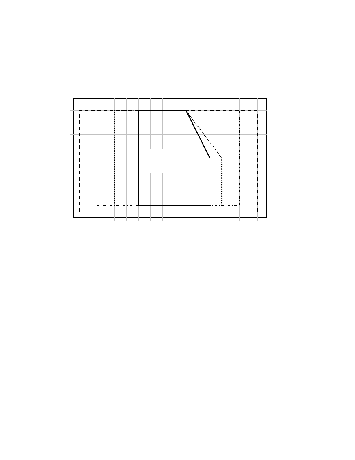
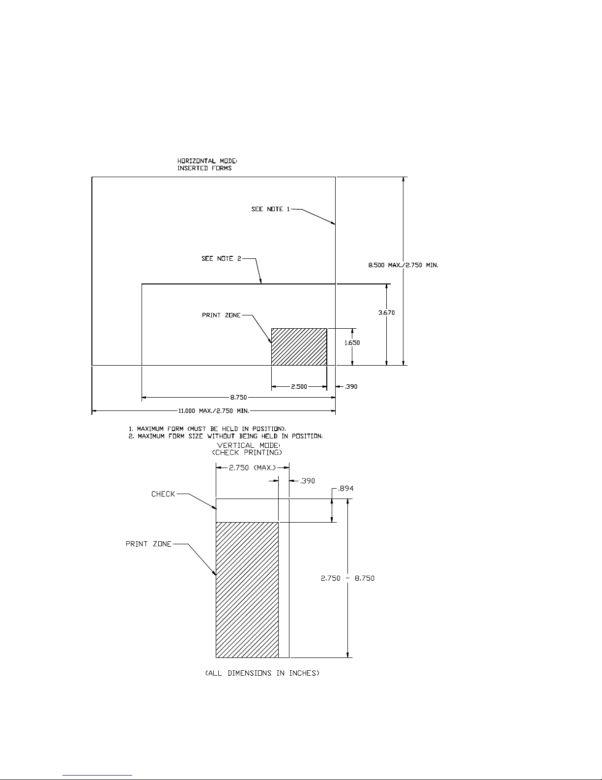
Validation Form Requirements
Form thickness-single part: .003" to .0047" (.076 mm. to .119 mm.)
Form Size (Min): 2.75" high x 2.75" long (69.8 mm. x 69.8 mm.)
Form Size (Max): 8.5" high x 11" long (215.9 mm. x 279.4 mm.)
# Validation lines: 9 lines @ 6lpi. 12 lines @ 8 lpi. (Max.)
Check Basis weight: 24 lbs.
Page 16 Rev M Nov-07
Figure 9 Form Print Zones
Page 31
Programmer’s Guide POSjet® 1500 Features/Specifications
Electrical Specifications
External Powered AC
The POSjet® 1500 Printer is designed to be AC self-powered in domestic and international markets. The printer is
equipped with a detachable universal input power supply that is designed to operate worldwide without
modification.
Supply Voltage
Rating (VAC)
100-240 90-264 47 - 63 25 0.08 @ 120VAC
Supply
Voltage
Range
(VAC)
Frequency
(Hz)
Table 9 Standard Power Input Requirements
Rated
Power
(watts)
Idle Current
0.04 @ 240VAC
(amps)
Printing Current
(amps)
.435 @ 100 VAC
.281 @ 240 VAC
External Powered DC
Optionally, the POSjet® 1500 Printer can be operated with an external 24-volt DC power supply.
Supply Voltage
Rating (VDC)
24-5+10% 22.8 -26.44 DC 25W
Table 10 Power Input Requirements Optional 24-volt DC Supplied from Host
Supply
Voltage
Range
(VDC)
Frequency
(Hz)
Power
(watts)
Avg.
(Printing)
Idle
Current
(amps)
0.125
Current (amps)
2.0 (Cash Drawer Fire)
1.0 (Printing)
Cash Drawer
Interface Description
The POSjet® 1500 Printer supports dual cash drawers with status. The driver in the printer is capable of supplying
24 V DC at up to 1.5 amps and 250 milliseconds. The POSjet® 1500 Printer defines cash drawer closed as switch
open. If the drawer is disconnected, the printer considers it closed. Since the printer does not act on the cash drawer
status, the application can interpret cash drawer status any way it wants.
• Driver connector type (standard) Single RJ12 connector (6 pin) with 24V sink drivers
• Driver voltage 24 volts (Refer to power supply specification)
• Driver current 1 amp maximum with current limit
• Pulse duration 250 msec maximum
• Drawer status Open/close drawer status provided to printer
The cash drawer interface can be configured for one of three configurations. The Communications Interface card
Board has a 14-pin header with a 10-pin shunt installed on it. The shunt position defines the configuration of the
Cash Drawer. There are three settings, Ithaca®, Epson, and Star.
Setup and Installation Procedures
4
For DC powered printers, the cash drawer is supplied directly from the DC input supply. The cash drawer
requirements may effect the allowable range of voltages.
Nov-07 Rev M Page 17
Page 32

Control Codes POSjet® 1500 Programmer's Guide
Overview of Printer Controls
Leaving the 1500 Connected to a Power Source
The POSjet® 1500 Printer uses Hewlett-Packard inkjet print cartridges. Unlike consumer inkjet print cartridges, the
HP print cartridge does not need to be capped when not in use. Consequently, the POSjet® 1500 is ready to print at
all times. The HP cartridge does not need to be sealed. However, the inkjet cartridge must have periodic usage to
maintain its functionality. The printer does this by cleaning the excess ink from the face of the cartridge (“wiping”)
and firing ink into a reservoir to clean the print jets (“spitting”). The printer performs these functions as
transparently to the host application as possible. However, the printer cannot perform these basic maintenance
procedures if the power to the printer is removed.
Do not unplug the printer from it’s power source. Instead, turn the printer to the STANDBY/OFF mode by
pressing and releasing the * Button located on the front face of the printer. Doing this prepares the ink cartridges for
periods of inactivity. Turning the printer to STANDBY/OFF maximizes the amount of time that the ink cartridge(s)
can be left without being used. When the printer is turned to STANDBY/OFF, it can sit unattended for a period of
time. To bring the printer back out of STANDBY/OFF mode, simply press the * Button. This will bring the printer
into OPERATIONAL/ON mode, which should be confirmed by the
Operating the Keypad Controls
The keypad contains 3 buttons and 6 indicator lights. The * Button is used in conjunction with the keypad controls
to perform operating tasks and is located on the front of the printer. The Open Cover Button is located on the left
side of the printer console. It is used to open the printer’s paper cover.
becoming illuminated.
Page 18 Rev M Nov-07
Figure 10 Keypad Buttons and Indicator Lights
Page 33

Programmer's Guide POSjet® 1500 Codes and Commands
Button Function Descriptions:
The primary functions of each of the buttons are described below. These buttons may also have alternate
functions when the printer is in self-test and configuration modes.
* Button
The * Button is located on the front of the printer. Since the POSjet® 1500 has been designed to remain connected to
a power source at all times, the * Button does not disconnect power to the printer, but instead switches the printer
between OPERATIONAL/ON and STANDBY/OFF modes. When the printer is in the OPERATIONAL/ON mode,
the green
will be illuminated. None of the keypad indicator lights are illuminated when the
printer is in the STANDBY/OFF mode.
The printer will always remember the current mode that it is in when power has been disconnected and then reconnected. For example, if the printer is in STANDBY/OFF mode and the power cord is unplugged and reconnected to the printer, it will remain in STANDBY/OFF mode. If the printer is in OPERATIONAL/ON mode and
the power cord is unplugged and re-connected to the printer, it will remain in OPERATIONAL/ON mode.
NEW CARTRIDGE Button
The Button works with the and right ink cartridge indicator lights to allow an operator to
monitor and replace ink cartridges as ink levels become low. The primary functions of the
Button are:
Cartridge Status Monitoring
Ink usage is monitored by the printer. When the ink supply is low, the indicator light for the left or right cartridge
will blink. After replacing the cartridge(s), press the Button to inform the printer that a new
cartridge has been installed.
Note: The printer cannot distinguish between a new, full cartridge and a used cartridge. When a cartridge is
replaced, the printer will reset the ink status to full when the Button is pressed. Used cartridges
should be discarded to assure that they are not re-installed into the printer
Printing Cartridge Status
Press the Button to print the current status of the ink cartridges. This function is only available
when the printer is in OPERATIONAL/ON mode, with paper and cartridges installed, and covers closed. It will not
remove an ink low warning unless the cartridge has been replaced.
Printing Ink Remaining Status
Pressing the Button once without changing the cartridge will print the ink status. It will not
remove the ink low warning unless the cartridge is removed and replaced while the low indication is being
displayed. If the cartridge is replaced with a used cartridge, the Button should not be pressed.
FEED Button
The Button is used to advance paper. If an inserted form is present in the printer, the FEED Button will move
the form in a upward direction. If no form is present, the receipt paper will be advanced.
Pressing the Button momentarily will feed one line at a time. Pressing and holding the FEED Button will feed
paper continuously until it is released. The receipt paper may be fed in the reverse direction by pressing and holding
the Button and the Button at the same time. The reverse feed function is mostly used
while fixing a paper jam.
Form Button
The Button is used for inserted form operations. Pressing the Button with no form inserted in the
printer activates the automatic form loading function. The printer will flash the
Nov-07 Rev M Page 19
and wait for
Page 34

Control Codes POSjet® 1500 Programmer's Guide
a form to be placed in the validation slot. If a form is already present in the printer, pressing the Button will
move the form in a downward direction.
Open Cover Button
The Button is used to access the rear paper roll compartment and is located on the top left side of the
printer’s outer console.
Indicator Light Descriptions
POWER INDICATOR LIGHT
ERROR INDICATOR LIGHT
PAPER INDICATOR LIGHT
FORM INDICATOR LIGHT
LEFT CARTRIDGE INDICATOR LIGHT
RIGHT CARTRIDGE INDICATOR LIGHT
The descriptions below reflect the normal uses of the keypad indicator lights. These indicators are also used during
self-test and errors modes to convey additional information.
Power Indicator Light (LED)
The
Error Indicator Light (LED)
The
, along with the other indicators may be used to determine the cause of the problem.
Indicates printer activity and non-recoverable errors.
Indicates problems and probability of recovery.
Indicates paper status (paper low and paper out).
Indicates validation/inserted form status
Indicates ink levels of left cartridge.
Indicates ink levels of right ink cartridge.
becomes active when the printer is in the OPERATIONAL/ON mode.
becomes active when a problem is detected by the printer. The
Paper Indicator Light (LED)
The
supply has been exhausted, the printer will stop, and the
is used to communicate the amount of paper remaining in the printer. When the paper
and
will illuminate. When
paper is reloaded, the indicator lights will be extinguished and the printer will resume operation. If the POSjet® 1500
is equipped with the optional paper low feature, the
will flash when the paper roll diameter
decreases below a preset minimum. This indication is a warning only, the printer will continue to operate normally
until the paper supply is exhausted.
Form Indicator
The
the operator that the printer is waiting for a form to be inserted/removed in the printer. The
is used during form validation operations. The
blinks to alert
will change to a steady ON condition when a form is present in the printer.
Left and Right Cartridge Indicator Lights (LED)
The printer has two ink cartridge indicator lights that display the status of the ink cartridges. The indicator light will
blink slowly when the ink level in the respective cartridge falls below a preset, programmable level. It is a warning
only, the printer will continue to operate without intervention. When ink cartridge(s) are removed, or the ink
cartridge is defective, the corresponding light will blink at a faster rate. Printer operation is inhibited until the
cartridge is replaced.
Page 20 Rev M Nov-07
Page 35

Programmer's Guide POSjet® 1500 Codes and Commands
Unpack the Printer
Be sure to save the box and packing materials in case you need to send the printer in for service. TransAct
Technologies is not responsible for damaged return items that are not packaged in original shipping material. Refer
to “Return Materials Authorization and Return Policies”, on page iv for information on what to do if you have to
return your printer for repair.
1. Open the box and remove the printer and all items. Check to make sure that all items are present.
• POSjet® 1500 Printer
• Ink Cartridge(s)
• Paper Roll (located under the paper cover)
• PowerPocket® Power Supply: located in cabinetry base (optional)
• AC Power Cord (optional)
• Configuration Summary Receipt
2. Separate the printer from the packing material. Reverse steps when repacking for return shipment.
3. Check the printer for any signs of damage. If the printer or any parts are damaged, report it to your supplier and
shipper immediately.
Nov-07 Rev M Page 21
Figure 11 Unpacking Instructions
Page 36
Control Codes POSjet® 1500 Programmer's Guide
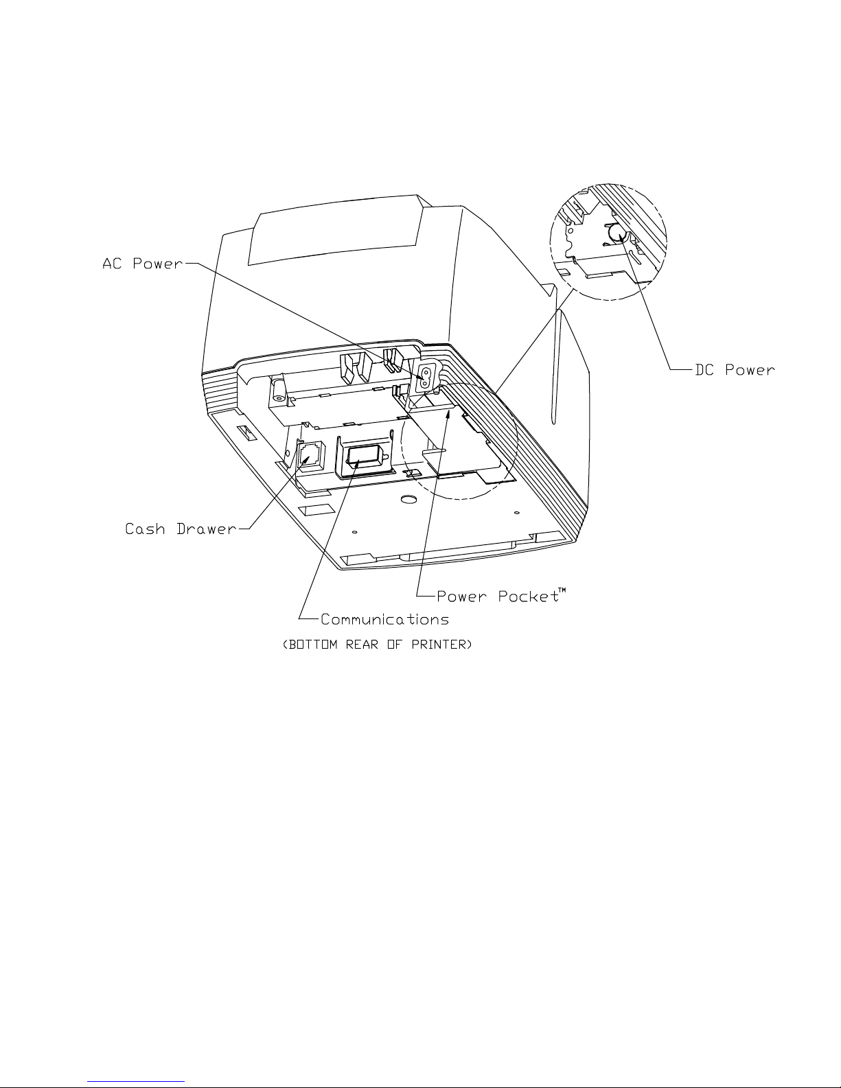
Connect Power and Communications
Installation Overview
Figure 12 Power and Communications Connections
Three cables are required to be connected to the printer
•
Power
•
Communications
•
Cash Drawer
Page 22 Rev M Nov-07
Page 37

Programmer's Guide POSjet® 1500 Codes and Commands
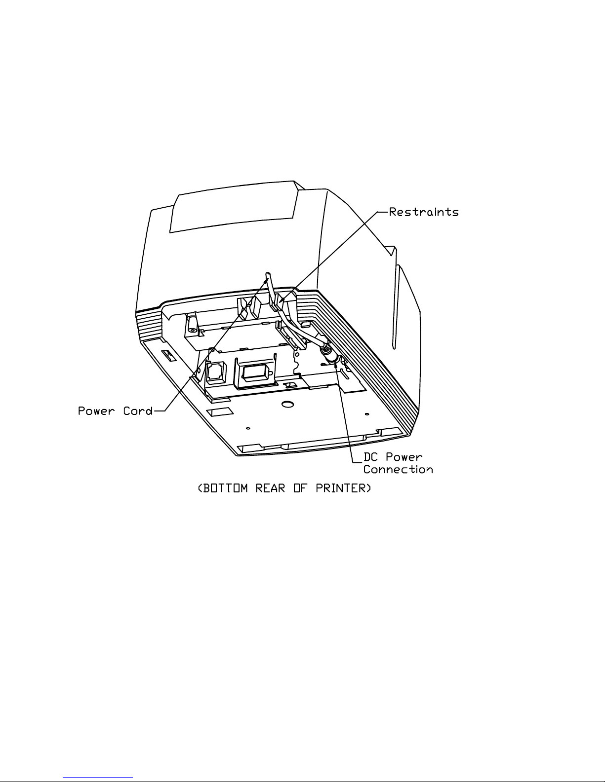
Using the Cable Restraints
Cable restraints are developed to protect against accidental unplugging of the printer while it is in use. Be sure to
properly route the communications cable using the restraints provided on the back of the printer.
Figure 13 Using the Cable Restraints
Nov-07 Rev M Page 23
Page 38

Control Codes POSjet® 1500 Programmer's Guide
Connecting the Communication Cable
The POSjet® 1500 may be equipped with a number of different communications interface cards.
These interfaces include:
RS-232 Serial with 9-pin connector
RS-232 Serial with 25-pin connector
IEEE1284 Parallel with 25-pin connector (IEEE1284-A)
IEEE1284 Parallel with 36-pin Centronics style connector (IEEE1284-B)
USB
Connect the appropriate communications cable to the printer as shown in the following figures. Cables are provided
by your dealer, the system installer or are available through TransAct. If you are unsure of the interface installed in
your printer, refer to “Verify the communications interface card” on page 35.
Connecting Serial Cables
1. Disconnect all power from the printer and host system or personal computer.
2. Connect the 9/25-pin Serial Interface Cable to the connector located on the back of the printer.
3. Tighten the two mounting screws on each side of the cable connector.
4. Route the Communication Cable through the Cable Restraint and connect the cable to your host system.
Figure 14 Connecting Serial Cables
Page 24 Rev M Nov-07
Page 39

Programmer's Guide POSjet® 1500 Codes and Commands
Connecting Parallel Cables
1. Disconnect all power from the printer and host system or personal computer.
2. Connect the 25/36-pin Parallel Interface Cable to the connector located on the back of the printer. Tighten the
two mounting screws on each side of the cable connector (25-pin only). Or, engage the locking clips (36-pin
only).
3. Route the Communication Cable through the Cable Restraint and connect to your host system.
Figure 15 Connecting Parallel Cable
Connecting USB Cables
Note: the USB connector can be “hot plugged”. The power does not need to be disconnected.
1. Connect the USB cable to the connector located on the back of the printer.
2. Route the Communication Cable through the Cable Restraint and connect to your host system.
Nov-07 Rev M Page 25
Page 40

Control Codes POSjet® 1500 Programmer's Guide
Connecting the Cash Drawer
The POSjet® 1500 printer can be configured to operate with cash drawers designed to work with printers from
different manufacturers. This configuration is preset at the factory and is identified by means of a label affixed to the
bottom of the printer. The POSjet® 1500 currently supports Ithaca, Epson, and Star compatible cash drawers.
CAUTION: The printer and cash drawer configurations must be the same to ensure proper operation. If the label is
missing or does not match your cash drawer configuration, refer to “Verify the Cash Drawer Interface” on page 36.
Connecting Cash Drawer Cable to the Printer
1. Disconnect all power from the printer and host system or personal computer.
2. Orientate the printer so you are looking at the rear underside of the unit and locate the small Cash Drawer
Connector to the left of the Communication Connector.
3. Connect the Cash Drawer Cable to the connector located on the back of the printer, making sure that the Cash
Drawer Cable snaps into place.
Figure 16 Connecting the Cash Drawer Cable
Page 26 Rev M Nov-07
Page 41

Programmer's Guide POSjet® 1500 Codes and Commands
The POSjet® 1500 Printer may be powered from an external 24 Vdc power source, or may be equipped with a
factory installed PowerPocket® power supply. Refer to the specification section for DC power connector
specifications.
Connecting the Power Cord (with power supply)
1. Orientate the printer upside-down and find the POSjet’s power supply’s power socket.
2. Locate the power cord and connect it to the power socket (power supply) located on the back of the printer and
to an external power outlet. The socket-outlet shall be installed near the equipment and shall be easily
accessible.
3. Route the power cord through the cable restraints. Refer to the drawing below to see how to route the cord.
Failure to use the cable restraints may result in the printer becoming accidentally unplugged during operation.
4. Set the printer into OPERATIONAL/ON mode by pressing the * Button. The printer takes approximately 1.5
seconds to begin operation.
Figure 17 Connecting the AC Power Cord (with power supply)
Nov-07 Rev M Page 27
Page 42
Control Codes POSjet® 1500 Programmer's Guide
Connecting the DC Power Cord (no power supply)
1. Orientate the printer upside-down and find the DC power socket.
2. Locate the DC power cord and connect it to the Interface Card’s power socket, then route the cord through the
cable restraint. Failure to use the cable restraints may result in the printer becoming accidentally unplugged
during operation.
3. Set the printer into OPERATIONAL/ON mode by pressing the * Button. The printer takes 1.5 seconds to begin
operation.
Figure 18 Connecting the DC Power Cord (no power supply)
Page 28 Rev M Nov-07
Page 43

Programmer's Guide POSjet® 1500 Codes and Commands
Low Sensor up or down by
Paper Low Setup
A receipt paper-low sensor is provided as an optional feature. This adjustable paper-low assembly allows the printer
to detect when the paper roll is between 1.42" and 0.885" (36.1mm and 22.4mm) in diameter, and to issue a paper
low status to the application. All printers are shipped with a mid-position setting, that can be adjusted up or down,
with 1 to 3 full turns of the adjustment screw. In general, the paper low setup does not need to be changed from the
factory setting.
Adjusting the Paper-Low Sensor
1. Use the Open Cover Button to release the rear paper cover and locate the paper low adjustment access hole.
2. Refer to Table 2 on the following page for specific adjustment settings.
3. Turn the screw to control the amount of paper that is remaining after paper low has occurred.
CAUTION: When the sensor touches the plastic of the Cabinetry Base (lower limit only), the sensor should not be
adjusted any further. Over adjustment will cause stress in the sensor material and will decrease its longevity.
Upper Limit Setting:
When adjusted, the sensor
will move up and away from
the Cabinetry Base. Do not
adjust anymore than 3 turns
counter clockwise from the
mid-position setting.
Factory Setting:
The factory setting leaves
room for adjusting the Paper
three full turns with a screw
driver.
#1 Phillips head
screw driver
Paper adjustment
access hole
Lower Limit Setting:
When adjusted, the sensor
moves down and toward the
Cabinetry Base. Do not
adjust anymore than 3 turns
clockwise, from the
mid-position setting.
Figure 19 Paper Low Setup (adjusting the sensor)
Nov-07 Rev M Page 29
Page 44
Control Codes POSjet® 1500 Programmer's Guide
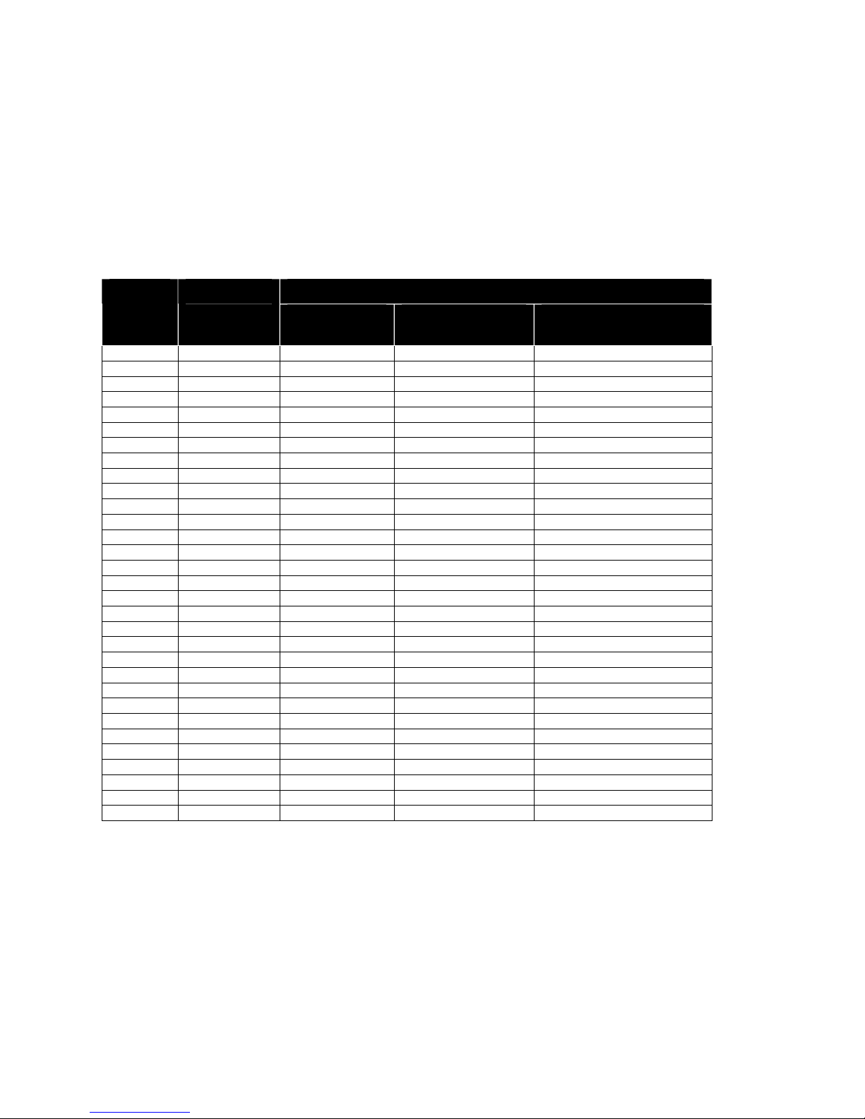
Paper Low Adjustment Requirements
Use the following table to decide how much paper you want to remain after paper low sensing has occurred.
TransAct’s expected results are based on paper and paper roll with these specifications. Refer to “Paper and Core
Diameter” on page 15 for paper measurements.
Paper Low Adjustment Settings Approximate Paper
Paper Roll Diameter
Remaining (in feet)
UPPER LIMIT: 3 turns (counter clockwise)
2 turns (counter clockwise) 22' 1.375" (34.9mm)
1 turns (counter clockwise) 16’ 1.250" (31.7mm)
FACTORY SETTING
1 turn (clockwise) 7' 1.050" (26.6mm)
2 turns (clockwise) 3.5' .950" (24.1mm)
LOWER LIMIT: 3 turns (clockwise)
Table 11 Paper Low Setup
24'
12'
1.25'
1.420" (36mm)
1.175" (29.8mm)
.885" (22.4mm)
Page 30 Rev M Nov-07
Page 45

Programmer's Guide POSjet® 1500 Codes and Commands
Loading Ink Cartridges and Paper
Note 1: FIRST TIME INSTALLATION: An ink cartridge(s) can be found in the pouch that shipped with your
printer.
NOTE 2: When installing new ink cartridges and a new paper roll for the first time, you may leave the cover
open until you have installed the ink cartridges, and the paper roll.
Installing Ink Cartridges
Use the * Button to set the printer into OPERATIONAL/ON mode before you install the ink cartridges. Confirm that
the printer is in this mode by checking that the
Caution: Do not touch the ink cartridge’s metallic connector surface with your fingers. Doing so will contaminate
the connector and produce sub-standard print quality.
1. Remove the new ink cartridge(s) from their sealed pouch and remove the Mylar tape from the face of the new
ink cartridge. (Holding the cartridge by the tab will ensure a clean installation.)
is activated.
2. Press the Open Cover Button to release the rear paper cover from the console, then swing the rear paper cover
towards the back of the printer. (Opening the printer’s front cover will also open the rear paper cover.)
Nov-07 Rev M Page 31
Page 46

Control Codes POSjet® 1500 Programmer's Guide
NOTE: If paper is present, ensure that the receipt is torn off prior to opening the front cover.
3. Pull down the blue cartridge latch/latches (1) and remove the old ink cartridges (2).
4. Place the new ink cartridge(s) into the carriage (3). Hold the cartridges by their tab to ensure a clean installation.
(Install the cartridge so that the tab is facing the front of the printer.) Close blue latch/latches (4).
5. Close all of the printer’s covers and press the Button. Doing this initializes the ink status on
the newly inserted ink cartridges.
NOTE: If you experience any problems, refer to “Printer Color Configuration” on page 58 to confirm that your
printer has the proper configuration settings.
Page 32 Rev M Nov-07
Page 47

Programmer's Guide POSjet® 1500 Codes and Commands
Installing a New Paper Roll Using Insta-Load®
Before you attempt to load the paper roll, make sure that the printer is plugged in and that the printer is set to the
OPERATIONAL/ON mode. !IMPORTANT!: Paper cannot be loaded for the first time without first installing the
ink cartridge(s). A small receipt roll is supplied with the printer.
ALWAYS check that the paper core is aligned with the right edge of the paper roll as installed.
1. Use the Open Cover Button to release the
rear paper cover; then swing it towards the
back of the printer to reveal the paper
compartment. (First time installers will
already have the cover open from
installing ink cartridges.)
2. IMPORTANT! Insert the new paper roll
so that the paper unwinds from the bottom
of the roll, and that the leading edge of the
paper rests on top of the front cover. Make
sure the paper does not extend beyond the
molded paper stop mark on the front
cover.
3. Close the rear paper cover; making sure
that it snaps into place. The printer will
automatically load the paper through the
feeding mechanism. If the paper does not
feed, repeat the steps.
Figure 20 Installing the New Paper Roll
Nov-07 Rev M Page 33
Page 48

Control Codes POSjet® 1500 Programmer's Guide
Printing the Configuration Summary Receipt
This printer has been shipped with a pre-printed, Configuration Summary Receipt that shows how the printer has
been configured at our factory. This Configuration Summary Receipt can be found in the paper compartment of your
printer. Save this receipt for future reference. In the event that you need to view your printer’s configuration settings,
but do not have your Configuration Summary Receipt, you can print a new one using the printer’s self-test mode.
Use the configuration summary receipt to compare printer configuration settings to your system requirements.
Specific attention should be given to ensure that the emulation and the communications link are properly configured.
If they do not match the settings of your system, the printer may appear inoperative.
Follow the steps below to print a new Configuration Summary Receipt:
Placing the Printer In Self-Test Mode (printing the Configuration Summary
Receipt)
The Button is used to enter the POSjet’s self-test mode. To place the POSjet® in self-test mode,
first be sure that a paper roll is loaded and that the
1. If the
is illuminated, press and release the * Button to turn the printer into
STANDBY/OFF mode.
2. Press and hold the Button.
3. While holding the Button, press and release the * Button.
4. When the red,
5. You are now in self-test mode. Read the directions on top of the printed receipt to cycle through the menu
options.
6. Select the “TEST-PRINT CONFIGURATION” menu option.
is off.
blinks, release the Button.
Exiting Self-Test Mode
Exit Self-Test mode at anytime by pressing the * Button to place the printer back into OPERATIONAL/ON mode.
At this point, your printer should be completely installed and ready to accept commands. Refer to our on-line
Operator’s Guide for additional information about setup troubleshooting, printer specifications, and
operational information.
Matching Printer Configuration Settings to your System
If you are experiencing inconsistent printing operation, or if the printer appears to be non-responsive, several of the
printer configuration settings need to be set to match the requirements of your system.
Parallel Printer
Emulation
Carriage Return Options
Serial Printer
Emulation
RS-232 Serial Interface (baud rate)
Carriage Return Options
TransAct recommends that ONLY THE ABOVE SETTINGS BE ALTERED and does not recommend that these
re-configurations be made by anybody but a trained service technician who has successfully completed
training on the POSjet® 1500. Please remember that these settings are only a few of the possible configurable
options. If you continue to experience incompatibility issues after changing these settings to match your
system, contact TransAct’s Technical Support Department for assistance.
Page 34 Rev M Nov-07
Page 49

Programmer's Guide POSjet® 1500 Codes and Commands
Verifying the Printer Setup
Before you install a POSjet® 1500 Printer into your system, you should verify that the printer is configured as
required by your system. There are four parts to this verification process.
1. Verify that the communications interface card is the correct one.
2. Verify that the cash drawer interface is configured correctly
3. Verify that the power connection is correct.
4. Verify that the firmware in the printer is configured correctly.
Verify the communications interface card
There are three basic types of interface cards and each has variations. Make sure your printer has the correct
interface card.
Parallel Interface
• Centronics 36-pin interface
• 25-pin D shell
Serial Interface
• 9-pin D shell interface
• 25-pin D shell interface
USB Interface
• Standard 4-pin
The POSjet® 1500 Printer can be installed to use either a 25-pin Serial and 25-pin Parallel interface card. To
determine what interface is installed refer to the configuration receipt shipped with the printer, or enter configuration
mode and look at the verification print out. If a serial interface card is installed, the print out will refer to the RS232 serial interface. If the parallel interface card is installed, the print out will refer to the Parallel interface.
Changing Interface Cards
The interface card on the POSjet® 1500 Printer can be changed in the field.
In most cases, interface cards are interchangeable without altering the printer firmware. However, you may have to
load new firmware and/or boot loader before you change the interface cards. Check with Technical Support for
firmware compatibility between interface cards before ordering.
Removing the Old Interface Card
1. Turn over the printer. Take care not to allow the cover to open or the paper to fall.
2. Disconnect the current communications and cash drawer cables.
3. If equipped, unsnap the power supply retainer and slide out the power supply.
4. Disconnect the power supply from the interface card.
5. Remove the interface retaining screw.
6. Slide the interface card sideways-towards the power supply pocket-and remove it.
MAKE SURE the cash drawer is configured correctly. (See the next page)
Nov-07 Rev M Page 35
Page 50

Control Codes POSjet® 1500 Programmer's Guide
Installing the new interface card
Configure the cash drawer jumpers. See "Verify the Cash Drawer Interface” on page 36.
1. Slide the interface card into the printer. Make sure the interface card sits flush with the retaining screw
mounting bracket. The retaining screw should also line up with the hole in the new interface card.
2. Install the retaining screw.
3. Reconnect the power supply to the new interface card.
4. Reinstall the power supply into the PowerPocket® and reattach the retainer.
5. Connect the communications interface card, and the cash drawer’s cables.
6. Turn over the printer, and reconnect the power.
Verify the Cash Drawer Interface
The printer is shipped from the factory with a cash drawer interface label on the bottom of the printer. You should
always verify that the cash drawer you are using matches the printer’s cash drawer interface label. If there is no
cash drawer label, you should remove the communications interface card and verify the setting.
There are many vendors of cash drawers. If you are unsure what the cash drawer interface is, contact the cash
drawer vendor for more information.
If you find that the cash drawer does not match the printer, you may change the printer's cash drawer interface
configuration as shown on page 17. If the cash drawer interface no longer matches the label on the printer, please
remove the label.
Matching the Cash Drawer Interface
Epson
Pin 1 Pin 1 Pin 1
Figure 21 Cash Drawer Selection
The cash drawer shunt setting is printed on the communications interface card. When you change the
communications interface card, it is very important that the cash drawer configuration of the new interface card
matches your cash drawer.
Star Ithaca
Page 36 Rev M Nov-07
Page 51

Programmer's Guide POSjet® 1500 Codes and Commands
Figure 22 Cash Drawer Shunt
See “Cash Drawer interface descriptions”, on page 17 to help determine what interface you need.
To reconfigure the interface card, remove the 5-position shunt and reposition it to the position that corresponds to
the cash drawer you have.
Nov-07 Rev M Page 37
Page 52

Control Codes POSjet® 1500 Programmer's Guide
POSjet® 1500 Operation
Using Ink Cartridges
The POSjet® 1500 is available in single or dual cartridge configurations. Several physical differences exist between
the single and dual cartridge printers. The most obvious is the ability to install two ink cartridges in a dual cartridge
printer. The second and less obvious is the dual wiper in a dual cartridge printer. For the printer to operate
correctly, the firmware needs to know the number of installed ink cartridges, and the color of both cartridges.
Carriage Configuration Left Pen Right Pen Wiper Configurations
Single Black Not Used Fixed Black Only
Dual (Color Ready) Black Not Used Dual Black - None
Dual Black Red Dual Black - Red
Dual Black Green Dual Black - Green
Dual Black Blue Dual Black - Blue
Dual Black Custom Dual Black - Red, Green, or Blue5
Table 12 Carriage Configurations
It is not possible to configure the printer to operate with two black cartridges. If a second black cartridge is
installed, the printer will not maintain it, and the cartridge will dry out and become unusable. Do not store a spare
cartridge in the second position. Once the seal is broken, the cartridge will be exposed to the air, and should be
placed in an operational printer.
Care of Ink Cartridges
Ink cartridges should be stored in the sealed HP packaging. Once a print cartridge is unsealed, it should be placed in
an operating printer. If a printer is taken out of service, the print cartridge should be removed and discarded. Never
ship a printer by any means with a print cartridge installed. The pressure variations can cause the cartridge to
become unprimed and/or purge. If you are going to ship a printer, remove and discard the print cartridge or
cartridges.
5
Custom second colors, when available, should select the closest primary color.
Page 38 Rev M Nov-07
Page 53

Programmer's Guide POSjet® 1500 Codes and Commands
Determining Ink Cartridge Status
The POSjet® 1500 has been designed to monitor ink consumption rates and report ink levels to the user via a
printable ink status. To print out an ink status receipt press the button.
Re-using cartridges will negate the printer’s ability to monitor ink consumption rates effectively. If the
button is pressed with a newly inserted used cartridge in place, the printer will reset the ink level
counter. Due to undetermined ink levels used cartridge, the printer’s counter will not be able to define the amount
that the cartridge is actually holding. TransAct does not recommend replacing a used cartridge with anything but a
new ink cartridge that is approved and compatible with the printer. TransAct recommends that used cartridges be
discarded after they are removed from the printer.
Refer to the following information as a guide for determining when ink cartridges need replacing.
Keypad Status Indicator Light (LED) Status and Sequence
Right Cartridge Low
Left Cartridge Low
Both Cartridges
Right Cartridge Removed
Left Cartridge Removed
Power LED ON
Error LED OFF
Paper LED OFF
Left Cartridge LED OFF
Right Cartridge LED 1 BLINK
Power LED ON
Error LED OFF
Paper LED OFF
Left Cartridge LED 1 BLINK
Right Cartridge LED OFF
Low Power LED ON
Error LED OFF
Paper LED OFF
Left Cartridge LED 1 BLINK
Right Cartridge LED 1 BLINK
Power LED ON
Error LED ON
Paper LED OFF
Left Cartridge LED OFF
Right Cartridge LED ON
Power LED ON
Error LED ON
Paper LED OFF
Left Cartridge LED ON
Right Cartridge LED OFF
Nov-07 Rev M Page 39
Page 54
Control Codes POSjet® 1500 Programmer's Guide
Validation Form Insertion and Orientation
Validation Orientation
The POSjet® 1500 accepts validation forms in both portrait and landscape orientations. Each of the two different
orientations have specific print zones, and print character spacing requirements. Regardless of the insertion
orientation, the minimum and maximum media size that can be accepted by the printer are as follows:
Form Requirements
Landscape Mode
Form size (Min.): 2.75” width x 2.75” height (69.8 mm x 69.8 mm).
Form Size (Max): 8.5” width x 11” height (215.9 mm x 279.4 mm).
Maximum Print Area: 2.5” width x 1.5” height
Portrait Mode
Form size (Min.): 2.75” width x 2.75” height (69.8 mm x 69.8 mm).
Form Size (Max): 2.75” width x 8.75” height (69.8 mm x 222.3 mm).
Maximum Print Area: 2.5” width x 7.8” height
In addition to the Min/Max size requirements, it is very important to use paper having a thickness between .003" to
.0047" (.076 mm. to .119 mm.). Using paper that is thicker than this may cause printing inconsistencies, and /or
paper jams. Refer to “Validation Form Requirements” on page 16 for a complete listing of specifications regarding
the use of validation forms.
Printer Settings
Form Orientation Character Line Spacing Number of printed character lines
Portrait (vertical) 10 character lines per inch 51 ( on 6 inch form)
Portrait (vertical) 10 character lines per inch 78 (on 8.75 inch form)
Landscape (horizontal) 8 character lines per inch 9
Landscape (horizontal) 8 character lines per inch 12
Table 13 Validation: Printer Settings and Requirements
Page 40 Rev M Nov-07
Page 55

Programmer's Guide POSjet® 1500 Codes and Commands
Inserting Validation Forms
The POSjet® 1500 is designed to run validation either by using application software, or manually. Forms can be
inserted in either landscape or portrait orientation. Regardless of the orientation, the insertion process is the same.
The POSjet® 1500 can accept forms with measurements between 2.75" x 2.75" (69.8mm x 69.8mm) and 8.5" x 11"
(215.9mm x 279.4mm).
1. Send appropriate control commands from your system to initiate the validation process or press the
Button to enter validation mode.
2. When the
the right edge (form stop) of the validation paper inlet as a guide.
3. When the validation sheet is detected by the sensors, the
steady ON. The paper is automatically drawn into the printer, and printing begins.
4. When the
starts blinking, insert the validation paper into the validation paper inlet using
changes from blinking to
begins to blink again after printing, remove the validation paper.
The side of the inserted form that is facing the front end of the printer is where the printing will always occur.
Always insert forms so that the side of the form that you want the printing to occur on is facing forward.
Nov-07 Rev M Page 41
Page 56

Control Codes POSjet® 1500 Programmer's Guide
Preventing and Clearing Validation Jams
Inserted forms should not be touched during the printing, or ejection process. Pressing or pulling the paper during
ejection may cause the validation process to jam. If a jam condition occurs, clear it as described below:
Removing a Validation Jam
If a validation jam occurs, and the top of the form is still visible in the form insertion area, remove the form by
simply pressing and holding the Button. If the top of the form is not visible in the form insertion area, it can
be removed manually.
Removing a Validation Jam Manually
1. Open the printer’s front cover.
2. Insert your index finger underneath the ink carriage and evenly pull the form out toward you until it is
completely removed from the printer.
3. Close the printer’s covers and resume operation.
Page 42 Rev M Nov-07
Page 57

Programmer's Guide POSjet® 1500 Codes and Commands
Printer Self Testing and Diagnostics
Printer Self-Testing
The POSjet® 1500 has been designed to perform several self-tests and will also allow a technician to access the
printer’s configuration settings. It is important to insure that the printer will perform a self-test. This isolates printing
problems to something other than the operation of the printer itself. The POSjet® has a total of ten self-test options
with four designed to be useful when performing on-site evaluations. These four tests are the only options that
should be used to test your printer. The other six testing options are used for printer demonstrations and factory
setup by TransAct. Use the following four test options when trying to correct a printing problem.
Use the following testing options when beginning to troubleshoot and repair the POSjet® 1500.
TEST-Receipt
The receipt test is the primary test option to use when determining if the printer is functioning correctly. The receipt
test is mostly used during the early stages of troubleshooting to eliminate the possibility that the problem is
occurring with the printer. If the printer experiences a failure, and the
TransAct’s Ithaca Facility’s Technical Support Department.
TEST-Print Configuration
The print configuration test is a quick and easy way for you to see how your printer has been configured at the
factory without actually having to enter into configuration mode. A large percentage of initial installation and setup
problems can be attributed to the printer’s configuration not matching the user’s system settings. Using this test will
show you the current configuration settings of the printer.
is activated, call
TEST-Validation
Validation test will validate the back of a check or inserted form. Nine lines of validation information will be
printed.
TEST-Check Test
Check test will perform the check insertion process and print a sample check test.
!"#!$ #"%&%!"'!"" '(
!"#!$ #"%&%!"'!"" '(
!"#!$ #"%&%!"'!"" '( !"#!$ #"%&%!"'!"" '(
The following six self-test options are only extended functionality tests and do not need to be run in order to
determine if the printer is running properly. These test options are only used for printer demonstrations and factory
setup.
TEST-Graphics
TEST-Print Specs
TEST-Validation
TEST-Check
TEST-Pyramid
TEST-Burn in
TEST-Bar Codes
TEST-Rolling ASCI
Nov-07 Rev M Page 43
Page 58

Control Codes POSjet® 1500 Programmer's Guide
Placing the Printer In Self-Test Mode
The Button may be used to enter the POSjet’s self-test mode. To place the POSjet® in self-test
mode, be sure that a paper roll is loaded. The
should not be illuminated when trying to
place the printer in self-test mode.
1. Press and release the * Button to switch the printer into STANDBY/OFF mode. (The
will be not be illuminated.)
2. Press and hold the Button.
3. While holding the Button, press and release the * Button.
4. When the red,
blinks, release the Button.
5. Follow the directions printed on the receipt to cycle through and select the desired TEST option.
Exiting Self-Test Mode
Exit Self-Test mode at anytime by pressing the * Button to place the printer back into OPERATIONAL/ON mode.
Remote Power Down
The POSjet® 1500 has a command that instructs it to turn the printer into STANDBY/OFF mode. When the
command is issued, the printer performs print cartridge maintenance and enters STANDBY/OFF. Unlike pushing
the * Button, remote power down mode leaves the communications active. All commands except the exit power
down command are ignored.
If the * Button is pressed after the power down command is issued, the printer will reactivate. If power is lost after
the power down command is issued, the printer will remember it is in STANDBY/OFF mode, but will not reactivate
the communications link. The * Button must be pressed to restart the printer.
Self-Test Hints and Suggestions
•
If the printer fails to complete or enter into self-test mode, disconnect it from the application system.
•
Contact TransAct’s Ithaca Facility’s Technical Support Department if self-test mode fails in any way.
Page 44 Rev M Nov-07
Page 59

Programmer's Guide POSjet® 1500 Codes and Commands
Level 0 Diagnostics
Level 0 diagnostics always and only run at power up.
Level 0 diagnostics perform the following tasks:
1. Basic System Integrity
2. Vector Integrity
3. RAM Test
4. Flash Boot Loader Integrity
5. Flash Firmware Integrity
6. Start Normal Firmware
7. Verify Configuration Integrity
8. Interface Card Configuration
9. User-store Integrity
10. Electronic Journal Integrity (and repair if necessary)
11. Start Kernel, Verify Multitasking, Start Tasks
Once the kernel is running, the following tests must pass to allow operation.
However, if any test fails (except the knife home test), the remaining tests
will generate recoverable faults and normal operation will start as soon as the
fault is cleared. These tests are also run when operation is resumed from
OFF.
12. Cartridge Integrity
13. Cover Closed Check
14. Knife Home (if installed)
15. Carriage Home
16. Schedule Cartridge Maintenance
17. Paper Present
18. Assure the validation path is clear.
19. Place Printer On-line, Start Normal Operation
Firmware Test
The flash test has two phases. The first phase determines that the boot loader is accurate, and the second verifies
that the printer firmware is correct. All tests, up to and including the boot loader test, generate non-recoverable
errors when they fail. The power must be removed from the printer, and the printer must be returned for service.
If the boot loader is intact, but the main firmware is bad, the printer automatically enters boot loader mode. The
firmware will re-loaded into the printer.
Boot Loader Mode
The boot loader cannot be entered during normal operation. Boot loader mode can only be entered in one of two
ways. One, when Level 0 Diagnostics finds that the firmware check CRC is bad, or two, manually. To manually
enter the boot loader, hold the * Button during power up. The
blinks. At this time, the firmware boot file may be sent to the printer. Level 0 diagnostics are prevented from
starting the firmware and boot load mode is forced to begin.
indicator comes on, and the
indicator
Nov-07 Rev M Page 45
Page 60

Control Codes POSjet® 1500 Programmer's Guide
Extended Diagnostics
Extended diagnostics are entered after Level 0 diagnostics, are part of the firmware, and are activated in one of two
ways. The first is by holdingbuttonand/or button and applying power (Power On).
The second is by holding buttonand/or buttonand activating the * Button from OFF or
Soft Power On.
OFF NEW
CARTRIDGE
Power On Off Off Normal Operation
Power On On Off Self Test Diagnostics
Power On Off On Manual Configuration
Power On On On
Soft Power On Off Off Normal Operation
Soft Power On On Off Color Alignment
Soft Power On Off On Hex-dump Print
Soft Power On On On Not Defined
Table 14 Extended Diagnostics
FEED TEST
Manual Emulation Set → Configuration
Self-Test Diagnostics
Self-test mode allows the printer to be tested to assure that it is working correctly. A number of tests may be run.
Self-test is entered by holding thebutton during initial power on.
Hex-dump Mode
To enter hex-dump mode, press and hold thebutton when resuming operation from OFF mode. Enter OFF by
pressing and releasing the * Button. Press and hold thebutton while pressing and releasing the * Button. Be
sure to release thebutton as soon as the carriage starts to move to prevent paper feeds.
Hex-dump mode is used to diagnose communication problems with the printer. As information is received by the
printer, the information is converted to a Hex/ASCII format and printed. No translation is made, which means no
commands are interpreted. All information is converted to Hex/ASCII and printed on the receipt. If a carriage
return is sent to the printer, it is translated to 0D in the hexadecimal field and "." in the ASCII field.
The format follows.
54 68 69 73 20 69 73 20 This is
61 20 74 65 73 74 0D 0A a test..
Several indications of printer and host communication problems can be deduced from hex dump mode. If the printer
is printing all 3F "?" symbols, the parity or the number of bits is wrong. If the printer is printing some Hex 3F "?"
signs when it should be printing other characters, either the parity, baud rate, or bit length setting is wrong. If the
printer prints incorrect characters (like Hex C1 instead of Hex 41 "A"), it is set for 8-bit data, and the host is set for
7-bit. In most cases, the print problem can be traced to the host and printer being configured differently.
Page 46 Rev M Nov-07
Page 61

Programmer's Guide POSjet® 1500 Codes and Commands
Configuration Mode
There are two ways to configure the POSjet® 1500 printer. The first is to use the manual configuration sequence by
using the keypad controls, and the second is to use TransAct’s remote configuration software. A remote
configuration program is available and typically used by system integrators. To obtain more information, or the
latest version of the configuration program, call our Sales Department or Technical Support.
!TransAct highly recommends that any attempt at configuring the POSjet® 1500 be made by a certified
service technician who has successfully completed training on the printer. TransAct is not responsible for
printer’s that are configured by anyone other than a trained technician!
Remote Configuration Software
This configuration program provides a means of configuring printers by using the printer’s remote configuration
mode. The configuration program is setup to provide initial (factory) printer configuration as well as allow the
printer to be reconfigured at any time. During factory configuration, the printer is configured as required by the
customer, and a serial number is embedded in the EEPROM. During the reconfiguration process, features and
communication configurations can be altered; however, the serial number cannot be changed. In remote
configuration mode, the serial or parallel port on the printer is temporarily reconfigured to a predefined standard.
The port is then used for the configuration or reconfiguration operation. The Ithaca Configuration program can
configure all configurable features. This program runs on most standard PC computers in Windows 95/98 and NT
4.0.
Manual Configuration
In many cases, manual configuration is locked by the remote configuration. If this is the case, the only way to
alter the configuration is by remote configuration.
Manual Configuration is a function of the printer that allows technicians to gain access to the printer’s configuration
mode. It is accessed by performing a series of steps. The POSjet® 1500 printer has many configurable features. Most
all of the configurable features can be configured by a certified technician using the keypad buttons while in
configuration mode. For example, if a dual color printer is to be operated with only one print cartridge, turning off
the dual color option will send all data to the single cartridge.
Manual Emulation Set
To allow easy predefined configurations to be loaded, the printer contains an internal default configuration for each
of the printer emulation's. The internal default configuration allows a starting point when changing the emulation.
To activate the manual emulation set, press and hold the
Manual emulation set offers more specific configuration options as what is covered in the regular configuration
options. (Note that the additional options are only offered once.)
It is important to note that each emulation can have different configurable features. If you are changing the
emulation, the printout that was printed at the beginning of the configuration process will document the initial
emulation settings. When you change the emulation, the configurable features may be different. If you are using
this printout as a configuration guide, and you are changing the emulation, you may wish to save the new emulation,
and then re-enter configuration mode to change other options. This will print all the available features for the new
emulation.
and
Buttons during power up.
Nov-07 Rev M Page 47
Page 62

Control Codes POSjet® 1500 Programmer's Guide
Using Self-Test to View Configuration Settings
From configuration mode, a configuration summary receipt will be printed and will show the printer’s current
features and settings. This receipt is the same as the configuration summary receipt that can be printed through the
self-test Mode. It is possible to print the configuration summary receipt using both the self-test, and configuration
mode. Therefore, TransAct recommends that self-test be used to print the printer’s current configuration receipt.
Printing the self-test configuration summary receipt is also recommended before ANY changes to the settings of
your printer are made by ANYONE. TransAct recommends that you print this configuration summary receipt as a
reference in case you wish to return the printer to its previous configuration state.
Entering Configuration Mode
Manually entering the printer’s configuration mode can be accomplished one of two ways. Both ways have been
designed to make it difficult to enter configuration mode. This has been done to prevent unintended entry into the
mode and unintentional configuration changes. The mode that is used depends on how the printer is setup. If you
do not have access to the power connection use the second procedure.
Access Option 1:
1. Unplug the power cord from the printer.
2. Press and hold the Button and plug the power cord back into the printer.
3. Continue to hold the Button until the
4. Release the Button. A receipt will print. This configuration summary receipt shows how your printer is
configured. Follow the directions at the bottom of the receipt to change and save configuration settings.
begins to blink.
Access Option 2:
1) Use the * Button to place the printer into STANDBY/OFF mode. (The
should not be
illuminated.)
2) Press and hold the
3) When the
Button while pressing and releasing the * Button.
blinks, repress the * Button and release the
Button. Then
release the * Button.
4) You are now in configuration mode.
After you enter configuration mode, the printer will print the current configuration, the current summary of printer
statistics, and an internal error log if any errors have been recorded. Save this printout as a guide to changing the
configuration. This printout is also helpful in case you wish to return the printer to the previous configuration
settings.
Page 48 Rev M Nov-07
Page 63

Programmer's Guide POSjet® 1500 Codes and Commands
Making Changes in Configuration Mode
Press the Button quickly to scroll through the list of configurable features. Press and hold the
Button to change the optional settings for each configurable feature. Press the * Button to exit
the printer’s configuration mode.
The printer will print a configuration summary, and prompt to confirm any changes that may have been directed into
the current configuration. Press the Button to confirm your changes, or, press the * Button, if
you do not want to save changes.
Using the NEW CARTRIDGE Button in Configuration Mode
The
the configuration menu, and save your specific configuration changes. Repeatedly pressing the
Button will allow you to select the desired configuration category. The categories will appear in sequence as shown
on the configuration summary receipt. When you arrive at the desired configuration category, press and hold the
1) Enter configuration mode.
2) Press and release the
3) Press and hold the
This will display the next available setting.
4) Repeat step 3 until the proper setting is shown.
5) Press and release the
6) Repeat step 3 until the proper setting is shown.
7) Press and release the
8) Repeat step 3 until the proper setting is shown.
9) Press and release the
10) Repeat step 3 until the proper setting is shown.
11) Press the * Button. This will print the current configuration.
12) Review the printout.
If the configuration is not correct press the * Button again and the new configuration will be discarded. You will
have to re-enter configuration mode and start over. If the Configuration is correct, press the
Button and the configuration will be saved.
What do you want to do? Do this…
Enter into configuration mode First, disconnect the power cord from the back of the printer.
Scroll through the configuration menu
Change specific configuration settings
Exit configuration mode
Button may be used to select configuration settings, change those settings, navigate through
Button to select the specific setting of that category.
Table 15 How to Change Configuration Settings
Button. This will display the current “Baud Rate”
Button. When the printer prints, release the
Button. This will display the “Mode”
Button. Until “Carriage Return” is shown.
Button. Until “Ink Low when at” is shown.
Next, press and hold the FEED Button while plugging the cord
back into the printer.
Press and quickly release the NEW CARTRIDGE Button.
Press and hold the NEW CARTRIDGE Button
Press and release the * Button
Button.
Nov-07 Rev M Page 49
Page 64

Control Codes POSjet® 1500 Programmer's Guide
Configurable Features
The following table lists all the configurable features. Not all are available in all configurations. Not all features are
available in all emulations. Refer to the Notes column for availability of each feature. If not noted, it is available.
Several emulations have sub-emulations. For example, the TM-U325 may be configured for 40 or 42 column mode.
Take care to configure the exact emulation you want. The TM-U325 emulation print out will list the corresponding
dip switch settings on the Epson printer. This is intended to help make sure the POSjet® 1500 printer is configured
the same way the Epson printer is configured. The bullet marks (•) in the following table signify that the option is a
POSjet default setting.
General Description and options Default Notes
Emulation
Mode
Emulation
Options
POSjet PcOS
The POSjet® 1500 printer supports 5 basic
printer emulation modes.
POSjet® 1500 PcOS
Epson TM-U325
ESC/POS (Not model specific)
Ithaca® M50 IBM
Microline M50, M50PLUS, ML192
The POSjet® 1500 printer supports variations on
several of the basic configurations
Print Zone: Normal 2.5 " or Simulated 2.8"
Block DC2 Control (AS400)
2.5
Off
Note: Not all emulations are
available in all versions of the
POSjet® 1500.
M50 and Microline are not
intended for new applications.
TM-U325
ESC/POS
M50
Microline
Input Buffer
Print Zone
Wide 42/35 Character
Narrow 40/33 Character •
ESC v Command is 2 or 3 characters
Block DC2 Control (AS400)
Print Zone: Normal 2.5 " or Simulated 2.8"
M50. M50PLUS or ML192 Emulation
BEL or ESC + CD command
Off
2.5
M50
BEL
Select Sequence
DC1 Select DC3 Deselect •
DC3 Select DC1 Deselect
Block DC2 Control (AS400)
Print Zone: Normal 2.5 " or Simulated 2.8"
Off
2.5
The input receive buffer can be configured to
various sizes. The optimal size is dependent on
the application. The options are from 40 bytes
to 8K bytes.
40
256
1024
2048
4096
8192 •
2
In TM-U325 mode this option
also effects the commands
available.
TM-U325
TM-U325 Default
Page 50 Rev M Nov-07
Page 65

Programmer's Guide POSjet® 1500 Codes and Commands
User Store
Locked
Lock On/Off
Switch
Configuration
Locked
Cash
Drawers
Time
Cash Drawer
Sense
Print Ink
Status
Audio Alert
Color
Options
Left Cartridge
Color
Right
Cartridge
Color
Graphic save lock configuration locks the
user-store buffers, so they cannot be deleted
by the application.
Enabled •
Locked
When the lock feature is functioning, the printer
is prevented from being turned off by the *
Button.
Enabled •
Locked On
The configuration lock feature prevents the
configuration from being altered manually.
If enabled, the printer can only be configured
with the configuration utility. (Note: locked
configuration cannot be manually set.)
Enabled •
Locked
Several features of the cash drawer logic can be
adjusted
Cash drawer fire time can be adjusted from 10
250 ms.
to 250 ms.
Invert Status (Normal or inverted sense)
Normal •
Inverted
When the NEW CARTRIDGE is pressed the ink
status is normally printed.
Ink status is printed •
Ink status is not printed
The initial signal time for the audio alert can be
adjusted
Time is adjustable from 100 mS to 1 Sec
Time is adjustable from 300 mS to 1 Sec •
The color and presence of the second pen can be
configured.
Cartridge Options
Black •
Red
Blue
Green
Cartridge Options
Not Installed •
Color Ready
Red •
Blue
Green
N
Not available in M50, or
Microline
Make sure the card is
configured correctly.
PcOS, M50, and Microline
only.
If 0 the alert is off or not
present.
Not available in M50 or
Microline.
Single Color Printers
Multi Color Printers
Single Color Printers
Multi Color Printers
Nov-07 Rev M Page 51
Page 66

Control Codes POSjet® 1500 Programmer's Guide
Ink Low When
At:
Print Zone
Vertical Control
Line Spacing
Auto
Line Feed/
Carriage
Return
Page Length
Fonts
Font
Pitch (CPI)
Signal ink low when x% of the ink has been
used.
Ink Low is OFF (never signal ink low)
Ink Low when at 75%
Ink Low when at 80%
Ink Low when at 85%
Ink Low when at 90%
Ink Low when at 95% •
Ink Low when at 100%
Normal 2.5” •
Simulated 2.8”
The line spacing can be defaulted to
6 or 8 lines per inch (lpi).
6 lpi
8 lpi •
An auto line feed feature can be set as a default
where all [CR]’s have a [LF] added. In
addition, a CR is added to a LF, and the CR
or LF can be configured to be ignored.
Normal CR/LF actions. Both are processed.
Ignore all LF characters
Ignore all CR characters
Add a LF to all CR characters
Add a CR to all LF characters •
Add a CR to all LF characters,
and add a LF to all CR characters
The default page length can be set to various
lengths from 2 to 60 lines. Page length
configuration affects how the [FF] command
operates.
2 to 60 lines
The default print mode can be set to 12 x 12
draft, 12 x 14 large draft, or 24 x 32 NLQ
modes.
12 x 12 draft •
12 x 14 large draft
24 x 32 NLQ
The default print pitch can be set to 8, 10, 12,
15, 17.1, 20, or 24 characters per inch.
8 cpi
10 cpi
12 cpi
15 cpi
17.1 cpi
PcOS
20 cpi
24 cpi
40
This sets the point when the
printer reports ink low. The
printer does not stop printing
at ink low
This is accomplished by
shrinking the character
spacing.
This is not available in and
TM-U325 mode
This is the default for most
Epson printers
Setting Depends
on emulation.
Default for most Epson
printers.
Page length can be set in
PcOS, M50, And Microline
only.
This is not configurable in all
emulations.
PcOS Only
Page 52 Rev M Nov-07
Page 67

Programmer's Guide POSjet® 1500 Codes and Commands
Code Sets
Code Pages
The POSjet® 1500 Printer supports the
following code sets. The setting defines only
the default printer mode. IBM specifies code
pages differently than Epson. Any set can be
selected as a default regardless of emulation.
However, the selections through software are
restricted by the emulation.
IBM Epson Description
64 - ASCII (Slashed 0)
65 - ASCII (Unslashed 0)
66 3 British
67 2 German
68 - French
69 5 Swedish I
70 - Danish
71 - Norwegian
72 14 Dutch
73 - Italian
74 13 French Canadian
75 - Spanish
76 15 Swedish II
77 16 Swedish III
78 17 Swedish IV
79 18 Turkish
80 19 Swiss I
81 20 Swiss II
91 - Welsh
93 93 Arabic6
437 0 USA •
774 74 Baltic_774
850 26 Multilingual
852 46 East Europe Latin II - 852
855 44 Cyrillic I - 855
857 57 Turkey_857
858 - Multilingual (Euro)
860 28 Portugal
861 73 Icelandic-861
862 60 Hebrew NC (862)
863 43 Canada French
865 27 Norway
866 21 or 45 Cyrillic II - 866
869 47 Greek_869
895 55 Kamenicky (MJK)
1008 38 Greek_437
1009 39 Greek_928
1011 41 Greek_437 CYPRUS
1012 29 Turkey
1013 21 or 45 Cyrillic II - 866
6
Arabic available on special order only.
Nov-07 Rev M Page 53
Page 68

Control Codes POSjet® 1500 Programmer's Guide
Code Sets
Code Pages
Zero
Character
Comm.
Interface
Off line Mode
1014 22 Polska Mazovia
1015 23 ISO Latin 2
1016 24 Serbo Croatic I
1017 25 Serbo Croatic II
1018 42 ECMA-94
1019 49 Windows East Europe
1020 50 Windows Greek
1021 51 Latin 5 (Windows Turkey)
1022 52 Windows Cyrillic
1024 54 Hungarian CWI
1026 56 ISO Latin 4(8859/4)
1027 66 Ukrainian
1028 58 Roman-8
1029 67 ISO Latin 6 (8859/10)
1030 60 Hebrew NC (862)
1031 61 Hebrew OC
1032 62 Windows Hebrew
1033 63 KBL-Lithuanian
1034 68 Windows Baltic
1035 69 Cyrillic-Latvian
1072 72 Bulgarian
- 1 French
- 4 Danish I
- 6 Italian
- 7 Spanish I
- 8 Japanese
- 9 Norwegian
- 10 Danish II
- 11 Spanish II
- 12 Latin American
- 254 Space
- 255 Space
The zero character can be configured to be
unslashed or slashed in all character sets except
IBM 64 and 65, which override the setting.
Unslashed
Slashed •
The POSjet® 1500 auto configures the
communication interface based on the card
installed. A few options apply to both serial
and parallel communication interfaces.
Off line mode defines when the printer
informs the host that it is off line.
Normal. The printer goes off line when the
buffer is full or the printer cannot print.
Buffer Full. The printer goes off line only when
the buffer is full. This mode requires that the
host request printer status from the printer.
•
This effects the ASB for TM
U325 and ESC/POS modes.
ASB Defaults off.
This should be selected for
Windows operation.
ASB Defaults all on.
Page 54 Rev M Nov-07
Page 69

Programmer's Guide POSjet® 1500 Codes and Commands
Parallel Link
Options
The parallel option features define how the
busy and acknowledge signals operate.
Ack-while-Busy
Ack-in-Busy •
Ack-after-Busy
Parallel Port
INIT Pin
10 CPI (DC2)
The parallel port INIT pin can be deactivated.
Active •
Inactive
Normal •
Disabled
Serial Interface Options
Parity
The serial mode parity can be set to none, odd,
or even.
None •
Odd
Even
Bit Data
The serial bit format can be set to 8 or 7.
8 •
7
Error
Character
If a communications error occurs, an internal
error is generated. The printer can be
configured to ignore the data or print a "?"
Enabled prints "?" •
Disabled ignores the data
Protocol
The flow control protocol of the serial link can
be set to Ready/Busy or XON/XOFF.
Ready/Busy functions when XON/XOFF is
selected.
Ready/Busy •
XON/XOFF
Baud Rate
The bit rate of the printer can be set. The same
bit rate is used for send and receive.
38400 BPS
19200 BPS •
9600 BPS
4800 BPS
2400 BPS
1200 BPS
600 BPS
300 BPS
DTR/RTS
Signal
The serial port DTR and/or RTS signal can be
configured to provide flow control. If DTR is
configured as the flow control signal, it toggles
to false when the buffer is full. RTS does not.
When the cover is opened, both signals always
toggle to false.
Not Used (Not valid unless in XON/XOFF
Mode)
DTR Flow
RTS Flow
RTS and DTR Flow •
Nov-07 Rev M Page 55
Page 70

Control Codes POSjet® 1500 Programmer's Guide
CTS Signal
Multidrop
Validation Control
Slip Auto
Reload
Manual Slip
Load
Auto Journal
Slip
Allow Form
Abort
Form Insert
Timer
Form
Remove
Timer
Default Slip
Stop
M50
Validation
Validation
Left Margin
Form Sense
Delay
Electronic Journal
If active, a false CTS prevents the printer
from sending any data to the host
Not Used •
Active
The multi-drop feature is activated at power up
when set to an address.
Off •
A Device
B Device
C Device
If this option is set, the printer will remain in
On
validation select mode until the form is inserted
correctly. If this mode is off the printer will
report an error to the host is the slip is not
inserted correctly. If this option is off, the host
must assure that the form is correctly inserted
before the validation information is sent to the
printer.
By default, pressing the FORM button will
ON
cause the printer to enter validation mode. This
feature may be disabled by turning this option
off.
If this option is selected, any information printed
Off
on a validation form will also be placed in the
Electronic Journal.
By default, pressing the FORM button while the
Enabled
printer is requesting a form will abort the form
request and return to receipt mode. This option
will disable this feature
This sets the time the printer waits for a
validation form before returning to receipt
mode.
This sets the time the printer waits for a
validation form to be removed before returning
to receipt mode
This specifies the default load point for
40 mm.
validation forms.
This option is available in M50 and Microline
Normal
emulations. It compresses the print (Vertically)
to allow applications written for the M50 to print
the same number of print lines on the 1500
This options sets the default left margin in
validation mode.
This sets the time the printer waits after a form
is sensed until the form is loaded.
100 ms. to
1 Sec.
•
•
0
•
This option is available in
PcOS, M50 and Microline
only.
The Electronic Journal must be
active for this option to function.
Disabled to 10 Min.
Disabled to 10 Min.
Note: There is a 1 Second Option
that is useful in some systems.
This value should not be set
greater than 40mm unless the
inserted form will always be less
than 70mm (2.75”) wide.
M50 and Microline only
100 ms. to 1 Sec.
300 ms. to 1 Sec.
Page 56 Rev M Nov-07
Page 71

Programmer's Guide POSjet® 1500 Codes and Commands
Electronic
Journal
This allows the partition of the extended flash to
be split between the electronic journal and the
user store. If the electronic journal is in use, this
64K to
Electronic
Journal
The configuration depends on the
amount of flash installed.
feature can not be changed.
EJ Print
Enable
There is a manual means to print the electronic
journal. This feature may be disabled by this
option. If the print is disabled, the only way to
Enabled
retrieve the EJ information is through the host.
EJ Print
Separator
Options
Cutter Option
Knife Pre-Cut
Feed
or
Tear Off
By default the printer will print a record
separator between journal records. This may be
disabled by this option.
Specifies that the cutter option is attached.
Not present or disabled
Active
The printer can be configured to feed from 0 to
26 mm of paper before the paper is cut.
If the auto cutter is not installed this value
becomes the tear point adjustment.
Enabled
Off
May be from 0 to 22mm.
adjustment
Table 16 Configurable Options
Note: There may be additional options and/or features that appear in the configuration list. If you wish to alter any
of these undocumented features you should call Transact Technical support for assistance.
Nov-07 Rev M Page 57
Page 72

Control Codes POSjet® 1500 Programmer's Guide
Printer Color Configuration
) !
) !*!
) !) !
•
•
•
•
Ink Cartridge Setup
The POSjet® 1500 is available with three different printing options and can be reconfigured to accept different ink
cartridge colors. See “ Configuration Mode” on page 47 for information on how to change configuration settings.
The standard printer setup is called Single Color. In addition to this, the printer can be operated with a Two Color
Ready, or a Two Color setup. All three of these printing setup options require different printer configuration
settings. The following information highlights the different functionality of each printing option and includes the
corresponding configuration settings that are needed to make each printing option perform correctly.
Single Color Setup
The Single Color printer setup is a factory built option. It is configured to handle a single ink cartridge and cannot be
field upgraded for two-color operation.
When using the POSjet with a single cartridge setup the left ink carriage should contain a single BLACK cartridge,
or a single color ink cartridge.
*!
*! *!
It is not possible to configure the printer to operate with two black cartridges.
Do not store a spare cartridge in the second carriage socket position.
Always store extra ink cartridges in the unopened original HP packaging until needed.
Do not replace an empty ink cartridge with anything but a new ink cartridge that is approved and compatible
with the printer.
Orange Carriage Spacer
(used for “Two Color Ready” operation only.)
Printing Setup Left
Cart.
Single Cartridge Operation Black
or any
color
Table 17 Single Color Printer-Color Configuration Details
Right
Left
Right
Cart.
None Fixed Factory built option. Not able t be updated in the field.
Wiper Selecting the configuration menu
settings:
No configuration required for operation.
Page 58 Rev M Nov-07
Page 73

Programmer's Guide POSjet® 1500 Codes and Commands
Two-Color Ready Setup (single cartridge setup)
The two-color ready setup allows the POSjet® to operate as a Single Color printer with the option of reconfiguring
the printer for two-color printing. This reconfiguration can be done at anytime by TransAct or any one of our
certified service technicians.
A printer that is setup with the two-color ready option but has no second cartridge in the right carriage always needs
to have the orange colored, plastic spacer in the right carriage. There is an auto-sense feature that attempts to auto
sense the presence of a second cartridge. This auto-sense feature will momentarily re-configure the printer for two
cartridge operation. The auto-sense is performed when power is applied to the printer (not with the * Button). If the
printer is power cycled without the second cartridge, the printer will revert back to single cartridge operation. When
the printer has the second cartridge installed, it should be reconfigured through software, or with manual
configuration, to be a two cartridge (color) printer. In addition to this, the printer needs the following configuration
settings:
Printing Setup Left
Cart.
Right
Cart.
Wiper Selecting the configuration menu
settings:
See “ Configuration Mode” on page 47
for information on how to change
configuration settings.
Two Color Ready
Operation
Black
or any
color
Table 18 Two Color Ready Operation-Color Configuration Details
Orange
spacer
required
Dual
Config. Menu
Option:
Left Cartridge Color
Black
Config. Menu Option:
Right Cartridge Color
Color Ready
Two Color Setup (two cartridge setup)
Two-color operation setup allows the POSjet® to operate as a two-color printer. Unlike the two-color ready setup,
the two-color setup does not use the orange colored spacer in the right carriage. Instead, the right carriage holds a
color ink cartridge, and is used along with the desired ink cartridge in the left carriage to produce two-color printing.
Color ink cartridges do not work in the left carriage socket. Use only black ink cartridges in the left carriage socket.
The color of the second cartridge should be configured into the POSjet® 1500 printer. The printer should be set to
Red, Green, or Blue. If the cartridge that is installed is not one of these primary colors, the nearest primary color
should be selected. For example if the cartridge is Orange, the nearest primary color is Red. A printer that is setup
to print multiple colors needs to have the following configuration settings:
Printing Setup Left
Two Cartridge
Operation
Black
or any
color
Table 19 Two Color Operation-Color Configuration Details
Cart.
Right
Cart.
Red
Green
Blue
Wiper Selecting the configuration menu
settings:
See “ Configuration Mode” on page 47
for information on how to change
configuration settings.
Dual
Left Cartridge Menu
Black
Red
Green
Blue
Right Cartridge Menu
Red
Green
Blue
Deactivating the Two-Color Setup (back to Single Color setup)
A printer that is setup for two-color printing can be reconfigured to print using only a single cartridge. This can be
achieved by resetting the left cartridge color to “BLACK” and the right cartridge color to “COLOR READY” using
the configuration menu. When “COLOR READY” is activated, all printing data will be sent to the left cartridge and
the printer will be able to print using a single cartridge in the left carriage only. When “COLOR READY” is
activated, the orange spacer needs to be re-inserted into the right carriage.
Nov-07 Rev M Page 59
Page 74

Control Codes POSjet® 1500 Programmer's Guide
Color Printing and Print Drivers
The POSjet® 1500 Printer has bit-image graphic capability and a full PC-compatible graphic character set. The bit
image format is similar to that used on other personal computer printers. Three modes of operation are available.
Single-density is the fastest mode. It makes a single unidirectional 60 dpi print pass. Full-speed double-density
mode makes two passes with a half-dot offset. Full-speed double-density mode is half the speed of single-density
mode, but it prints at 120 dpi. Half-speed double-density mode is half the speed of full-speed double-density;
however, the print quality is enhanced.
Character Graphics
Character graphics is the term for joining individual characters together to produce a mosaic of characters that form
a graphic image. The simplest method uses an * (or any other character) to form an image. For example, ITHACA®
might be formed as follows.
*** *** * * ** *** **
* * * * * * * * * *
* * ***** **** * ****
* * * * * * * * * *
*** * * * * * *** * *
Figure 23 Example of Character Graphics
The extended character set of the printer supports line graphic characters that can be combined to form windows and
other shapes. For the shapes to join from line to line, the spacing must be set properly. All characters are in a ninedot-high character cell. The dots are 1/60 inch apart. Therefore, the line spacing should be 10/60 or 1/6 inch. The
set fine line space command can be used to set the line spacing. If possible, the spacing should be reduced slightly
to overlap the rows, which prevents any white spacing from appearing between the lines. The following example
illustrates the use of extended character graphics.
[ESC]:[ESC]3<27>[ESC]a<1>
<201><205><205><205><205><205><205><205><205><205>
<205><205><205><205><205><205><205><205><205><205><205><205><205><187>[CR][LF]
<186> PcOS PRINTERS <186>[CR][LF]
<186> <186>[CR][LF]
<186> MADE TO ORDER <186>[CR][LF]
<186> BUILT TO LAST <186>[CR][LF]
<200><205><205><205><205><205><205><205><205><205>
<205><205><205><205><205><205><205><205><205><205><205><205><205><188>[CR][LF]
[ESC]a<0>[ESC]0[ESC][P<15>[CR][LF]
ST# 2000 OP# 00067 TE# 021 0035[CR][LF]
KLEENEX FAM D04 QTY 1 1.68 J[CR][LF]
RITZ D01 QTY 1 2.50 D[CR][LF]
CHIPS D01 QTY 1 1.50 D[CR][LF]
STORAGE BAG D04 QTY 1 1.50 J[CR][LF]
SUB TOTAL 7.18[CR][LF]
SALES TAX 1 .50[CR][LF]
------[CR][LF]
TOTAL 7.68[CR][LF]
CASH TEND 20.00[CR][LF]
CHANGE DUE 12.23[CR][LF]
[CR][LF]
[ESC]a<1>
THANK YOU FOR SHOPPING WITH US[CR][LF]
[ESC]a<0>
[CR][LF]
{DATE:0} {TIME:0}[CR][LF]
[ESC]d<10>
Figure 24 Example Commands for a Sample Receipt
Page 60 Rev M Nov-07
Page 75

Programmer's Guide POSjet® 1500 Codes and Commands
Figure 25 Sample Receipt
When printing line graphics, the data path to the printer must be eight bits. Seven-bit serial protocols do not access
the extended characters. The extended characters require that the form be reverse fed. Consequently, printing line
graphics on the receipt may be less than acceptable.
APA Graphics
The printer is capable of all-points-addressable (APA) or horizontal graphics. Generating a graphic image by hand
is time consuming and tedious. It is recommended that a graphic package be used to create a graphic image. The
following procedure will help with the setup.
Creating an APA graphics file
1. Generate the graphic image in the program of your choice. APA graphics only support monochrome images.
2. Make sure the paper size chosen fits the printer (3 inches wide with 0.25-inch margins). If the paper size cannot
be set, print a portion of the page.
3. Print the graphic to a file using a generic, IBM, graphic, 9-pin driver. The standard IBM resolutions are 240 x
216 dpi, 120 x 72 dpi, and 60 x 72 dpi. The POSjet® 1500 Printer supports all three resolutions. For good
resolution with reasonable speed, use 120 x 72 dpi.
4. Print the graphic image to a file.
5. Edit the resulting file to remove any unwanted form control, and insert the POSjet® 1500 form control.
6. Make the resulting file available to your application, so it can be sent to the printer when required.
Nov-07 Rev M Page 61
Page 76

Control Codes POSjet® 1500 Programmer's Guide
Color Graphics
The POSjet® 1500 is a two-color printer. It is not a full color printer. A full color printer forms the various colors of
an image by mixing inks of different colors on the paper. The amount of each color determines the hue. Typically
the paper is white and no ink produces a white dot. Mixing yellow and cyan produces a red dot and mixing cyan,
magenta, and yellow in equal amounts produces a black or gray dot. If the printer has a forth cartridge, it will be
black.
The POSjet® 1500 is a two-color printer. It has white (the paper), black (an ink cartridge), and one other premixed
color (a red cartridge for example). The printer does not mix the inks on the paper. It either leaves the paper color,
prints a black dot, or a color dot. To allow the POSjet® 1500 to use colors other than red, the architecture of the
color provides for the sending of three-color plains to the printer.
There are two ways to define colors, CMY and RGB. CMY stands for cyan, magenta, and yellow. Mixing cyan,
magenta, and yellow can be compared to blending paint. When cyan, magenta, and yellow are mixed, the result is
black. RGB stands for red, green, and blue. Mixing red, green, and blue together can be compared to blending light
beams. When the lights are turned off, everything looks black. When all the lights are on, the result is white.
Because the POSjet® 1500 Printer does not mix colors, either CMY or RGB color definitions work.
For the POSjet® 1500 Printer, RGB color definition was chosen because the colors are closer to those most often
used in print, and as a result, RGB color definition generally requires sending less data to the printer. It also turns
out to be convenient for Windows to generate data because RGB color definition is the same as the display.
The printer does not have a gray scale and cannot print various hues of color. Therefore, only two bits per pixel are
required. To allow multicolor support, three bits per pixel are available. (Compression reduces the data back to two
bits). After the data is decompressed in the printer, each dot contains three bits of information. The color print
algorithm follows.
Second Cartridge Color Color Bits Received
Red Green Blue
Red Green Blue Black Red Black Green Black Blue
OFF OFF OFF X X X
ON ON ON
ON OFF OFF X
OFF ON OFF X
OFF OFF ON X X X
ON ON OFF X X X
OFF ON ON X X X
ON OFF ON X X X
Table 20 Color Bits Received
The Ithaca® Windows print driver provides the translation from Windows color to the three-color plains. When a
graphic is created for the POSjet® 1500 Printer, the colors used must take into account that colors other than the pen
color will print black. The Ithaca® Windows driver helps adjust the color content and generates the desired print
from a full color image.
(Ithaca® Windows print driver patent pending.)
Page 62 Rev M Nov-07
Page 77

Programmer's Guide POSjet® 1500 Codes and Commands
Procedure for color horizontal graphics:
There are many ways to generate graphics for the POSjet® 1500 printer. The easiest is to use the PJColor program.
(See the next section.) The other way is to use the Ithaca windows driver and capture the output to a file.
To generate an image using the windows print driver:
1. Generate the graphic image in the program of your choice. Use colors consistent with the two colors installed
in the printer.
2. Make sure the paper size you pick fits the printer (3 inches wide with 0.25-inch margins).
3. The POSjet®15000 print driver should be installed (even if the printer is not connected).
4. Set up the print driver to print the graphic to a file using whatever resolution is required.
5. Print the graphic image to a file.
6. Later, when you want to print the graphic, simply copy the file to the printer with your application.
7. You may also copy the graphic to the graphic save buffer and then request the printer to retrieve and print it
without re-sending the graphic data.
Optionally, process the color image with the Ithaca® color image processor7 in the PJColor program. The program
can print the image or generate a printable file.
As with all graphics, the data path to the printer must be eight bits. Seven-bit serial protocols do not work.
7
Ithaca® Color Image Processor is patent pending
Nov-07 Rev M Page 63
Figure 26 Receipt with graphics
Page 78

Control Codes POSjet® 1500 Programmer's Guide
Printer Drivers and Printer Controls
General Driver Information
The following information provides a brief descriptive overview of each of the printer drivers that the POSjet® 1500
can be integrated with:
Windows Printer Driver:
A Windows printer driver is a Microsoft specific, Microsoft defined, type of driver that the OS uses to translate
drawing commands by a Window’s application to a specific printer’s command set. A window’s printer driver is a
graphics page mode driver. It is not a POS (Point of Sale) driver. A Windows Printer Driver should be used when
writing a program that uses the Window’s API to send print information to the printer. Do not attempt to use a
printer driver when a program wants to send printer command codes to the printer or when a program wants to get
information back from a printer.
OPOS Driver:
An OPOS Driver is not a printer driver.
An OPOS driver is a POS device driver that an application uses to get a POS device to do something. Types of
OPOS drivers are POSPrinter, Scanner, Cash drawer, Pole Display, MICR, and Scale. An OPOS Driver should be
used when you want to be able to access all the features of the POS device and you do not want to send
printer/device specific commands to the printer/device. OPOS Driver are also used when you want to get
information back from the device in a standard (OPOS) way, or when you want to be able to use devices from
different vendors. Do not use OPOS Drivers when attempting to send device specific commands to the
device/printer.
POSPrinter ActiveX Control (OCX):
This is not a driver; it is a software component that provides a connection from an application to a port driver. This
allows an application to communicate “directly” with a printer. This approach allows an application to send the
commands, it wants to, to the printer and is similar to the “DOS way” of communicating with a POS printer. Active
X Controls should be used when attempting to control what is sent to the printer. When using Active X Controls it
is very important to send the correct codes to the printer as well as detecting error conditions with the printer and
graceful recovery from error situations. Do not use Active X Controls if you do not want to interact with any lowlevel commands sent to the printer.
Page 64 Rev M Nov-07
Page 79

Programmer's Guide POSjet® 1500 Codes and Commands
Installing Windows® Printer Drivers (WIN95, 98, Me)
1. Insert the “Windows 98, 98, Me printer driver” floppy disk into your diskette drive.
2. Click on “Start” menu -> “Settings” -> “Printers”.
3. Double Click on “Add Printer” Icon.
4. Select “Next”.
5. Select “Local Printer” and “Next”.
6. Click on “Have Disk”, if your floppy is A: use A:\ and then “OK”.
7. Select the printer you have (ie. Series 1500) and then “Next”
8. If you are asked “Keep existing driver” or “Replace Existing Driver”. Choose “Replace existing driver”
and then “Next”.
9. Select the port the printer is connected to, and then “Next”.
10. Select “Yes” or No” for default printer, Printer name should not be altered, so choose “Next”.
11. If you wish, you can print a test page. Although, due to the narrow paper stock that this printer uses and the
margins windows chooses, there will not be enough room to print all the images of the test page. Some of the
large text will word wrap and be truncated.
12. Select “Finish”. The printer driver is now installed.
13. If you selected “Replace existing driver”, reboot your machine to ensure all components are installed.
Printer Driver Installation Instructions for NT4.0, 2000
1. Insert the “Windows NT, 2000 printer driver” floppy disk into your diskette drive.
2. Click on “Start” menu -> “Settings” -> “Printers”.
3. Double Click on “Add Printer” Icon.
4. Select “My Computer” and “Next”.
5. Select the port the printer will be connected to, and then “Next”.
6. Click on “Have Disk”, if your floppy is A: use A:\ and then “OK”.
7. Select the printer you have (ie. Series 1500) and then “Next”.
8. If you are asked “Keep existing driver” or “Replace existing driver”. Choose “Replace existing driver”
and then “Next”.
9. Printer name should not be altered, so choose “Next”.
10. Select “Not Shared” -> “Next”.
11. If you wish, you can print a test page. Although, due to the narrow paper stock that this printer uses and the
margins windows chooses, there will not be enough room to print all the images of the test page. Some of the
large text will word wrap and be truncated.
12. Select “Finish”. The printer driver is now installed.
13. If you selected “Replace existing driver”, reboot your machine to ensure all components are installed.
Nov-07 Rev M Page 65
Page 80

Control Codes POSjet® 1500 Programmer's Guide
OPOS Drivers Installation Instructions
Run SetupOPOS.exe.
The communications will default to “COM2”. If the communication port is not setup at installation, the first time
the printer service object Open method is called, a Comm port setup dialog will be displayed. After running
Setup.exe there will be a OPOS setup utility in the OPOS program group/start menu and also in the control panel.
Use this utility to setup the OPOS printer “driver” and cash drawer “driver”. To Install the USB drivers:
Ensure that USB is enabled in your system's BIOS. To verify that USB is enabled, Click on "Start", "Settings",
"Control Panel". Double click "System" and select the "Device manager". If you see "Universal Serial Bus
Controllers" in the list, USB is enabled. Check your PC's documentation for more information about USB if needed.
Ensure that power is applied to the printer and plug in the USB cable to both the PC and printer.
Follow the on screen directions. Please note that several drivers are installed in this process. Therefore the "Found
new hardware" prompt will appear several times. If the system needs, direct it to the location of the USB driver
install disk (usually the floppy drive).
See “readme.txt” or “usbman.htm” on the install disk for more information.
To Install the USB drivers
1. Ensure that USB is enabled in your system's BIOS. To verify that USB is enabled, Click on "Start",
"Settings", "Control Panel". Double click "System" and select the "Device manager". If you see
"Universal Serial Bus controllers" in the list, USB is enabled. Check you PC's documentation for more
information about USB if needed.
2. Ensure that power is applied to the printer and plug in the USB cable to both the PC and printer.
3. Follow the on screen directions. Please note that several drivers are installed in this process. Therefore the
"Found new hardware" prompt will appear several times. If the system needs, direct it to the location of the
USB driver install disk (usually the floppy drive).
See “readme.txt” or “usbman.htm” on the install disk for more information.
Page 66 Rev M Nov-07
Page 81

Programmer's Guide POSjet® 1500 Codes and Commands
Configuring Windows® Printer Drivers (WIN95, 98, Me)
The standard Windows printer driver configuration properties are described in the operating system’s help under the
“printers” topic. The Ithaca specific configuration is described below.
Start/EndDoc Tab
Use these setting to cause additional actions to happen at the start and end of a document.
Additional StartDoc Commands:
This is where you place text and binary commands that you want sent to the printer before a document is printed.
Additional EndDoc Commands:
This is where you place text and binary commands that you want sent to the printer after a document is printed.
Line Feeds:
This is where you enter the number of line feeds that will be done after a document is printed.
Cut Receipt:
This option will send a cut command to the printer after the document is printed.
Fire Cash drawer 1:
This option will send a fire cash drawer 1 command to the printer after the document is printed.
Fire Cash drawer 2:
This option will send a fire cash drawer 2 command to the printer after the document is printed.
Note: For these options to work the printer driver must be in “bi-directional” mode. To check this, go to “Details”
tab, “Spool settings”. For NT and Win 2000, go to the “ports” tab.
Nov-07 Rev M Page 67
Page 82

Control Codes POSjet® 1500 Programmer's Guide
Font Options Tab (Win 9x/Me only)
These options control how font processing is handled in the printer driver.
Note: Selecting “Always map fonts to device resident fonts” causes the printer driver to behave in a way that is not
how the operating system expects a printer driver to operate. This is not the default mode of operation and can
cause the printed output to vary depending on the settings you choose.
True Type Fonts
These settings control capability flags that are reported to the operating system.
Device Fonts:
These settings control how printer resident fonts get selected. These settings force the driver to behave in a nonstandard way. These “Device Font” settings can make up for an application that does not select a printer resident
font.
Additional Text formatting
These settings control how text gets printed in the print zone and the spacing between lines.
Line Truncation Control
These settings control oversized line lengths are handled.
Note: The printer’s custom driver settings are stored in the Windows system registry. These custom settings
persist even if you uninstall the driver. You can view, edit, and delete these setting via RegEdit.exe that comes with
Windows. Using RegEdit.exe can render you system unusable and lead to a loss of data on your computer, extreme
caution should be used when editing the system registry. You should backup you registry before you edit it (see
Windows help for more information).
It is recommended that the custom settings be changed via the printer’s property pages as discussed previously in
this document.
Page 68 Rev M Nov-07
Page 83

Programmer's Guide POSjet® 1500 Codes and Commands
To view, edit, or delete the custom settings
Go to the Windows operating system’s start RegEdit.exe and go to
HKEY_LOCAL_MACHINE\SOFTWARE\PcOSPrinter\Series_1500 for the Series 1500 printers.
Nov-07 Rev M Page 69
Page 84

Control Codes POSjet® 1500 Programmer's Guide
Configuring Ithaca OPOS Drivers
To configure the OPOS drivers, either run the “Ithaca OPOS Setup” in the control panel or run the configuration via
the “Start” menu, “Programs”, “Ithaca OPOS”, “Ithaca OPOS Setup”. You must choose the communications port
(and the port setting in the case of a serial port). At the OPOS printer configuration, you can set the following:
Printer driver
Choose the printer that you are using. “SeriesAutoDetect” can automatically detect which printer is connected. This
auto detection will allow switching of Ithaca series printers without changing host system settings.
Rename:
This will allow you to rename the OPOS device name. Some applications look for a specific name for the device to
use. This renaming will accommodate an application of this type.
Remove:
This will allow you to remove an OPOS device from the system.
Set as Only:
This will allow you to set this device as the only device of this type (printer). Some applications look for the first
device name for the device to use. To ensure that a device is the first one, use this setup feature. Caution should be
exercised when using this setup feature, this “Set as Only” will remove all other OPOS devices of this type (printer).
Note: An entry may be first alphabetically, but not first to be enumerated by the operating system.
Printing
Default Characters Per Line:
This is the default number of character per print line. The number of characters per line is typically set by the
application. If the application does not set the number of characters per line, this default will be used.
Line Feed Scale Factor:
This controls the base/default line height/spacing. Increase this value for a larger line spacing.
Fast Bitmap Printing:
Set to have bitmaps print in the fastest mode possible (while xxxLetterQuality is false). If xxxLetterQuality is set to
true, the “Fast Bitmap Printing” option is overridden and bitmaps are printed in high quality mode. If “Fast Bitmap
Printing” is off and xxxLetterQuality is set to false, bitmaps are printed in a medium quality mode.
Double High = Double Line Feed:
If set, when a line feed is encountered after double high print is requested, a double line feed will be done.
Print Red as Bold:
If set, a request for alternate color print (red) will be printed as bold.
Truncate Trailing Spaces:
If set, spaces on the end of a line of text will be removed. This truncation can be used to prevent unwanted line
wrapping.
Page 70 Rev M Nov-07
Page 85

Programmer's Guide POSjet® 1500 Codes and Commands
General Settings
Paper Low = Paper Out:
If set, paper low will not be reported until paper is out.
Inhibit Events:
If set, events will not be generated.
Error Events Asynchronous Mode Only:
Set to enable firing error events while in A-synchronous mode only. If not set, error events will be fired in both Asynchronous and Synchronous modes.
Set Error String on Synchronous Error:
If set, the ErrorString will be set when an error occurs while calling a method in synchronous mode. Other wise it
will only be set in asynchronous mode.
Synchronous Time Out:
Time in milliseconds a synchronous print method will wait before returning a OPOS_E_TIMEOUT. If set to -1
(0xffffffff), a synchronous print method will never time out (default).
Synchronous Error Wait:
Time in milliseconds a synchronous print method will wait for an error condition to be removed before returning an
error. If the error condition is removed before this time has elapsed, the print method will be processed.
Performance
Background Status Updating:
If set, printer status will be updated in the background. This background updating will increase performance. This
performance increase is because when a print request is made the status is obtained from a previous background read
and not when the print method is called. Due to the fact that the parallel interface operates in half duplex, it is
especially important using a parallel interface.
Printer Never Busy:
If set, the printer service object (“driver”) will report that the printer is not/never busy. This will greatly increase
synchronous printing performance. Synchronous print calls will not wait for the printer to actually be idle. It should
be noted that this “never busy” mode is not strictly compliant with the OPOS specification. This performance
increase is especially important using a parallel interface, due to the fact that the parallel interface operates in half
duplex.
Communications Port:
Port Name:
This is the name of the communications port (ie. COM2, LPT1).
Setup Comm Port:
This will display a communications setup dialog. You will be able to set things such as baud rate and handshaking.
Note: these settings must match the printer you are using.
I/O Time Out Factor:
This controls how long the driver waits for I/O. Its value can range from 10 to 2000. The smaller this value is, the
more responsive the application will be when the printer is off or disconnected.
Nov-07 Rev M Page 71
Page 86

Control Codes POSjet® 1500 Programmer's Guide
Paper Out:
Ignore Paper Out:
If this is selected, the print functions will still attempt to print to the printer even when paper out is sensed. This
functionality is provided to maximize paper use on the Ithaca Series 90 printer that reports paper out as a function of
the number of print lines since paper low is sensed. Use on printers other than the Series 90 is not recommended.
You must have printer configuration “Paper Out Mode” set to “Disabled” to use this functionality.
Do not Report Paper Out:
If this is selected, the printer driver will not report that paper is out even when paper out is sensed. This
functionality is provided to maximize paper use on the Ithaca Series 90 printer that reports paper out as a function of
the number of print lines since paper low is sensed. Use on printers other than the Series 90 is not recommended.
You must have printer configuration “Paper Out Mode” set to “Disabled” to use this functionality.
Cash Drawer Dialog
Drawer 1 or 2:
Select which drawer is the default cash drawer that is fired. This default setting can be overridden at run time via
“DirectIO”. See: “PcOS OPOS Reference Manual” (PcOSOPOS.doc) for more information.
Drawer Open Status Immediately:
If set, the driver will begin to report that the cash drawer is open as soon as the command is given to open the
drawer. This option is provided to allow for applications that expect different event timing than the hardware
generates.
Reverse Drawer Open Sensor Detection:
Some cash drawer sensors are wired opposite than expected. An example of this can be seen when comparing the
difference between (Normally open NO) vs (Normally closed NC). This setting allows for a cash drawer whose
sensor is connected differently than expected.
Number of Drawer Open Retries:
If non-zero and the cash drawer fails to open, the cash drawer driver will try to re-fire the cash drawer at
approximately 2 second intervals the number of times specified.
Wait For Drawer Open Timeout:
This is the time that the OpenDrawer() function will wait for the cash drawer to open. If the drawer does not open
within this time, the function will return an OPOS_E_TIMEOUT. If set to -1 (0xffffffff), OpenDrawer() method will
never time out.
Message Beep Type:
Normally set to -1. When set to -1 will use PCs speaker as a beeper. This value is passed to the windows API
MessageBeep() function.
Drawer Wait Timeout:
Time in milliseconds that WaitForDrawerClose() method will wait before returning a OPOS_E_TIMEOUT. If set to
-1 (0xffffffff), WaitForDrawerClose() method will never time out.
Page 72 Rev M Nov-07
Page 87

Programmer's Guide POSjet® 1500 Codes and Commands
Printing using a printer driver (Printer Font)
See the documentation that comes with Visual Basic for detailed information on all the function calls that can be
made to print via the Windows printer drivers.
'SELECT OUR PRINTER BY NAME
For Each x In Printers
If x.DeviceName Like "Series 1500" Then
Set Printer = x
Exit For
End If
Next
'SELECT FONT BY NAME
Printer.FontName = "NLQ 10cpi"
Printer.Print " 20 Bomax Rd"
Printer.Print " Ithaca, NY 14850"
Printer.Print ""
Printer.Print ""
Printer.Print ""
Printer.FontName = "Draft 16cpi"
'SELECT BOLD PRINT
Printer.Font.Bold = True
Printer.Print "ITEM PRICE"
Printer.Font.Bold = False
Printer.Print "Cheese Wiz $1.49"
Printer.Print "Crackers $2.59"
Printer.Print "Laundry Soap $3.29"
Printer.Print "Printer Paper $3.89"
Printer.Print "Rubber Bands $ .99"
Printer.Print "Soda $1.49"
Printer.Print "Candy $2.29"
Printer.Print "-------------------------------------"
Printer.Print " Sub Total $16.03"
Printer.Print " Tax $1.28"
Printer.Font.Bold = True
Printer.Print " TOTAL $17.31"
Printer.Font.Bold = False
Printer.Print " ---------------------------"
Printer.Print " Cash $20.00"
Printer.Print ""
Printer.Font.Bold = True
Nov-07 Rev M Page 73
Page 88

Control Codes POSjet® 1500 Programmer's Guide
'CHANGE COLOR
Printer.ForeColor = RGB(255, 0, 0)
Printer.Print " Change Due $2.69"
Printer.ForeColor = RGB(0, 0, 0)
Printer.Font.Bold = False
Printer.Print ""
Printer.Print ""
Printer.Print ""
Printer.Print ""
Printer.EndDoc
Printing via a printer driver (System/Graphical/TrueType Font)
This is the preferred way to print via a Windows printer driver to a page printer.
'SELECT OUR PRINTER BY NAME
For Each x In Printers
If x.DeviceName Like "Series 1500" Then
Set Printer = x
Exit For
End If
Next
'SET FONT SIZE
Printer.FontSize = 10
'SELECT FONT BY NAME
Printer.FontName = "Arial Black"
Printer.CurrentX = 1000
Printer.Print "20 Bomax Rd"
Printer.CurrentX = 800
Printer.Print "Ithaca, NY 14850"
Printer.Print ""
Printer.Print ""
Printer.Print ""
'SELECT FONT BY NAME
Printer.FontName = "Arial"
'SELECT BOLD PRINT
Printer.Font.Bold = True
Page 74 Rev M Nov-07
Page 89

Programmer's Guide POSjet® 1500 Codes and Commands
'SET PRINT POSITION
LinePos = Printer.CurrentY
Printer.Print "ITEM"
Printer.CurrentX = 2800
Printer.CurrentY = LinePos
Printer.Print "PRICE"
Printer.Font.Bold = False
LinePos = Printer.CurrentY
Printer.Print "Cheese Wiz"
Printer.CurrentX = 2900
Printer.CurrentY = LinePos
Printer.Print "$1.49"
LinePos = Printer.CurrentY
Printer.Print "Crackers"
Printer.CurrentX = 2900
Printer.CurrentY = LinePos
Printer.Print "$2.59"
LinePos = Printer.CurrentY
Printer.Print "Laundry Soap"
Printer.CurrentX = 2900
Printer.CurrentY = LinePos
Printer.Print "$3.29"
LinePos = Printer.CurrentY
Printer.Print "Printer Paper"
Printer.CurrentX = 2900
Printer.CurrentY = LinePos
Printer.Print "$3.89"
LinePos = Printer.CurrentY
Printer.Print "Rubber Bands"
Printer.CurrentX = 2900
Printer.CurrentY = LinePos
Printer.Print "$ .99"
LinePos = Printer.CurrentY
Printer.Print "Soda"
Printer.CurrentX = 2900
Printer.CurrentY = LinePos
Printer.Print "$1.49"
LinePos = Printer.CurrentY
Nov-07 Rev M Page 75
Page 90

Control Codes POSjet® 1500 Programmer's Guide
Printer.Print "Candy"
Printer.CurrentX = 2900
Printer.CurrentY = LinePos
Printer.Print "$2.29"
Printer.CurrentY = Printer.CurrentY + 100
Printer.Line (0, Printer.CurrentY)-(3600, Printer.CurrentY)
Printer.CurrentY = Printer.CurrentY + 100
LinePos = Printer.CurrentY
Printer.CurrentX = 1300
Printer.Print "Sub Total"
Printer.CurrentX = 2800
Printer.CurrentY = LinePos
Printer.Print "$16.03"
LinePos = Printer.CurrentY
Printer.CurrentX = 1300
Printer.Print "Tax"
Printer.CurrentX = 2900
Printer.CurrentY = LinePos
Printer.Print "$1.28"
Printer.Font.Bold = True
LinePos = Printer.CurrentY
Printer.CurrentX = 1300
Printer.Print "TOTAL"
Printer.CurrentX = 2800
Printer.CurrentY = LinePos
Printer.Print "$17.31"
Printer.Font.Bold = False
'Printer.Print "---------------------------"
Printer.CurrentY = Printer.CurrentY + 100
Printer.Line (1300, Printer.CurrentY)-(3600, Printer.CurrentY)
Printer.CurrentY = Printer.CurrentY + 100
LinePos = Printer.CurrentY
Printer.CurrentX = 1300
Printer.Print "Cash"
Printer.CurrentX = 2800
Printer.CurrentY = LinePos
Page 76 Rev M Nov-07
Page 91

Programmer's Guide POSjet® 1500 Codes and Commands
Printer.Print "$20.00"
Printer.Print ""
Printer.Font.Bold = True
'CHANGE COLOR
Printer.ForeColor = RGB(255, 0, 0)
LinePos = Printer.CurrentY
Printer.CurrentX = 1000
Printer.Print "Change Due"
Printer.CurrentX = 2900
Printer.CurrentY = LinePos
Printer.Print "$2.69"
Printer.ForeColor = RGB(0, 0, 0)
Printer.Font.Bold = False
Printer.Print ""
Printer.Print ""
Printer.EndDoc
Printing via an OPOS driver
There are 3 Modes of printing.
1. Synchronous mode, printing is done before the print function returns.
2. Asynchronous mode, print function returns as soon as it can, printing may or may not be done yet.
3. Transaction mode buffers all print data and the print data is sent all at once.
See the documentation that comes with the Ithaca® OPOS drivers for detailed information on all the function calls
that can be made via the OPOS drivers.
OPOS drivers are first “Opened”, “Claimed” and “Enabled” before they can be used. This is typically done when the
application starts (Form Load in VB).
CallResult = Printer1.Open("SeriesAutoDetect")
Printer1.Claim (6000)
Printer1.DeviceEnabled = True
Then the device is used (i.e. printing is done)
Dim Data As String
‘SET NUMBER OF CHARACTERS PER LINE
Printer1.RecLineChars = 33
Nov-07 Rev M Page 77
Page 92

Control Codes POSjet® 1500 Programmer's Guide
Data = "********************************" + Chr(13) + Chr(10)
CallResult = Printer1.PrintNormal(PTR_S_RECEIPT, Data)
Data = "* *" + Chr(13) + Chr(10)
CallResult = Printer1.PrintNormal(PTR_S_RECEIPT, Data)
Data = "* Fast Mart *" + Chr(13) + Chr(10)
CallResult = Printer1.PrintNormal(PTR_S_RECEIPT, Data)
Data = "* *" + Chr(13) + Chr(10)
CallResult = Printer1.PrintNormal(PTR_S_RECEIPT, Data)
Data = "********************************" + Chr(13) + Chr(10)
CallResult = Printer1.PrintNormal(PTR_S_RECEIPT, Data)
Data = Chr(13) + Chr(10) + Chr(10) + Chr(10) + Chr(10)
CallResult = Printer1.PrintNormal(PTR_S_RECEIPT, Data)
Data = Chr(27) + "|rA" + "Bread 1.49" + Chr(13) + Chr(10)
CallResult = Printer1.PrintNormal(PTR_S_RECEIPT, Data)
Data = Chr(27) + "|rA" + "Milk 2.19" + Chr(13) + Chr(10)
CallResult = Printer1.PrintNormal(PTR_S_RECEIPT, Data)
Data = Chr(27) + "|rA" + "Rice .99" + Chr(13) + Chr(10)
CallResult = Printer1.PrintNormal(PTR_S_RECEIPT, Data)
Data = Chr(27) + "|rA" + "Soup 2.49" + Chr(13) + Chr(10)
CallResult = Printer1.PrintNormal(PTR_S_RECEIPT, Data)
Data = Chr(27) + "|rA" + "Nuts 3.49" + Chr(13) + Chr(10)
CallResult = Printer1.PrintNormal(PTR_S_RECEIPT, Data)
Data = Chr(27) + "|rA" + Chr(13) + Chr(10) + "--------------------------" +
Chr(13) + Chr(10)
CallResult = Printer1.PrintNormal(PTR_S_RECEIPT, Data)
Data = Chr(27) + "|rA" + "TOTAL 10.65" + Chr(13) + Chr(10)
CallResult = Printer1.PrintNormal(PTR_S_RECEIPT, Data)
Data = Chr(13) + Chr(10) + Chr(10) + Chr(10) + Chr(10)
CallResult = Printer1.PrintNormal(PTR_S_RECEIPT, Data)
Data = "Thank you for Shopping with us" + Chr(13) + Chr(10)
CallResult = Printer1.PrintNormal(PTR_S_RECEIPT, Data)
Data = "Come again soon" + Chr(13) + Chr(10)
CallResult = Printer1.PrintNormal(PTR_S_RECEIPT, Data)
Data = Chr(27) + "|90fP"
CallResult = Printer1.PrintNormal(PTR_S_RECEIPT, Data)
Page 78 Rev M Nov-07
Page 93

Programmer's Guide POSjet® 1500 Codes and Commands
When the device is no longer needed it is “Disabled”, “Released” and “Closed”. This is typically done when
the application is being shutdown. (Form Unload in VB).
Printer1.DeviceEnabled = False
Printer1.Release
Printer1.Close
Setting Fonts, Justification (left, right, center), Bold, Double wide/high, ... (from vbtest)
'Font Typeface #1
data = Chr(27) + "|1fT" + "Font Typeface #1" + Chr(10)
CallResult = Printer1.PrintNormal(PTR_S_RECEIPT, data)
'Font Typeface #2
data = Chr(27) + "|2fT" + "Font Typeface #2" + Chr(10)
CallResult = Printer1.PrintNormal(PTR_S_RECEIPT, data)
'Font Typeface #3
data = Chr(27) + "|3fT" + "Font Typeface #3" + Chr(10)
CallResult = Printer1.PrintNormal(PTR_S_RECEIPT, data)
'Font Typeface #0
data = Chr(27) + "|0fT" + "Font Typeface #0 (default)" + Chr(10)
CallResult = Printer1.PrintNormal(PTR_S_RECEIPT, data)
'Bold
data = "This is " + Chr(27) + "|bC" + "Bold" + Chr(10)
CallResult = Printer1.PrintNormal(PTR_S_RECEIPT, data)
'Underline
data = "This is " + Chr(27) + "|uC" + "Underline" + Chr(10)
CallResult = Printer1.PrintNormal(PTR_S_RECEIPT, data)
'Italic
data = "This is " + Chr(27) + "|iC" + "Italic" + Chr(10)
CallResult = Printer1.PrintNormal(PTR_S_RECEIPT, data)
'2xWide
data = "This is " + Chr(27) + "|2C" + "2xWide" + Chr(10)
CallResult = Printer1.PrintNormal(PTR_S_RECEIPT, data)
'2xHigh
data = "This is " + Chr(27) + "|3C" + "2xHigh" + Chr(10)
CallResult = Printer1.PrintNormal(PTR_S_RECEIPT, data)
'2xWide 2xHigh
data = "This is " + Chr(27) + "|4C" + "2xWH" + Chr(10)
CallResult = Printer1.PrintNormal(PTR_S_RECEIPT, data)
'2x Normal
data = "This is " + Chr(27) + "|4C" + "2x" + Chr(27) + "|1C" + " to Normal" + Chr(10) + Chr(10)
Nov-07 Rev M Page 79
Page 94

Control Codes POSjet® 1500 Programmer's Guide
CallResult = Printer1.PrintNormal(PTR_S_RECEIPT, data)
'Left
data = "This is Left" + Chr(10)
CallResult = Printer1.PrintNormal(PTR_S_RECEIPT, data)
data = "This is More Left Text" + Chr(10)
CallResult = Printer1.PrintNormal(PTR_S_RECEIPT, data)
data = "This is Less" + Chr(10) + Chr(10)
CallResult = Printer1.PrintNormal(PTR_S_RECEIPT, data)
'Center
data = Chr(27) + "|cA" + "This is Centered" + Chr(10)
CallResult = Printer1.PrintNormal(PTR_S_RECEIPT, data)
data = Chr(27) + "|cA" + "This is More Centered Text" + Chr(10)
CallResult = Printer1.PrintNormal(PTR_S_RECEIPT, data)
data = Chr(27) + "|cA" + "This is Less" + Chr(10) + Chr(10)
CallResult = Printer1.PrintNormal(PTR_S_RECEIPT, data)
'Right Justified
data = Chr(27) + "|rA" + "This is Right Justified" + Chr(10)
CallResult = Printer1.PrintNormal(PTR_S_RECEIPT, data)
data = Chr(27) + "|rA" + "This is More Right Justified Text" + Chr(10)
CallResult = Printer1.PrintNormal(PTR_S_RECEIPT, data)
data = Chr(27) + "|rA" + "This is Less" + Chr(10) + Chr(10)
CallResult = Printer1.PrintNormal(PTR_S_RECEIPT, data)
'Paper feed (RecLinesToPaperCut) and cut
data = "Feed(RecLinesToPaperCut) cut" + Chr(10)
CallResult = Printer1.PrintNormal(PTR_S_RECEIPT, data)
data = Chr(27) + "|90fP"
CallResult = Printer1.PrintNormal(PTR_S_RECEIPT, data)
Page 80 Rev M Nov-07
Page 95

Programmer's Guide POSjet® 1500 Codes and Commands
Printing via POSPrinter OCX
See the documentation that comes with the POSPrinter OCX for detailed information on all the function calls that
can be made with the POSPrinter OCX.
Dim StrData As String
Result = POSPrinter1.SetHandshake(2)
'Result = POSPrinter1.OpenPort("LPT1:", "")
Result = POSPrinter1.OpenPort("COM2:", "baud=9600 parity=N data=8 stop=1")
If Result <> 1 Then
MsgBox "OpenPort failed, make sure no other devices are using this port."
End If
StrData = "Hello World" + Chr(13) + Chr(10)
Result = POSPrinter1.SendString(StrData, Len(StrData))
If Result <> 1 Then
MsgBox "SendString failed, Ensure that the printer is connected to the port."
End If
Result = POSPrinter1.SendString(Chr(5) + Chr(21), 2)
StrData = POSPrinter1.ReadString(100)
Result = POSPrinter1.ClosePort()
Nov-07 Rev M Page 81
Page 96

Control Codes POSjet® 1500 Programmer's Guide
Troubleshooting
Indicator Lights (LED)
The five POSjet® 1500 indicator lights are:
• Power LED Indicates printer activity and non-recoverable errors
• Error LED Indicates problems and probability of recovery
• Paper LED Indicates paper status (paper low/paper out)
• Left Cartridge LED Indicates ink levels of left cartridge
• Right Cartridge LED Indicates ink levels of right ink cartridge
• Form LED Indicates the Validation Form needs attention.
Power Indicator (LED)
The
indicator lets the user know that the printer is ON. If the
indicator, the printer is experiencing a non-recoverable error. See the fault indicators below. If the
indicator blinks, and there is no
indicator blinking, the printer is being held in reset by the host.
indicator blinks in conjunction with the
Error Indicator (LED)
The
indicator lets the user know that the printer is experiencing a problem. If the
blinking), the error is generally recoverable without data loss. If the
error has occurred. See fault indicators below. If the error is not operator recoverable, a power cycle may correct
the problem. If a power cycle does not correct the fault, the printer must be serviced.
indicator is blinking, a non-recoverable
indicator is lit (not
Paper Indicator (LED)
The
indicator signals the paper status. If the printer is equipped with a paper low option, the
will blink when the paper is low. The low sensor is adjustable, and the amount of paper remaining is dependent on
the adjustment. If the
printing and waits for the paper to be changed.
indicator is lit with the
indicator, the printer is out of paper. The printer stops
indicator
Form Indicator (LED)
The indicator signals that the form is active, should be inserted or removed. If the indicator is blinking the
form should be inserted or removed. If the indicator is on steady, the printer is in validation mode.
Cartridge Indicators (LED-left and right)
The printer has two ink cartridge indicators that signal the ink cartridge status. The right indicator is for the right
cartridge and the left indicator for the left cartridge. If the printer is a single color printer, the left cartridge indicator
is used. In most cases, the left cartridge is black, and the right is a highlight color.
Cartridge is low on ink (1 Blink, pause) _____________________
Cartridge has been removed (Blinking, error) ________________
Note 1 If both ink cartridges are low, the button only needs to be pressed once; however, both
heads must be changed.
Fault Indicators
Page 82 Rev M Nov-07
Page 97

Programmer's Guide POSjet® 1500 Codes and Commands
The error indicator is the primary fault indicator. It is always on or blinking if a fault has occurred.
Three types of faults exist
• Fully-recoverable faults Paper out or cover open
• Semi-recoverable faults Head Jam
• Non-recoverable faults Component failure
Fully-recoverable
A fully-recoverable error will restart printing exactly where it stopped when the error occurred. Printing will resume
after error has been properly addressed. A semi-recoverable error is very similar to a fully-recoverable error.
Additionally, status is used to display when the printer consumables may need replacing.
Semi-recoverable
A semi-recoverable error is determined by whether or not the printer has to be shut off and turned back on while
attending to the problem. The amount of information lost is dependent on the type of error and the state of the
information being processed.
Non-recoverable
A non-recoverable error likely produces information loss.
If during normal operation, the
The
indicator shows the error by blinking a pattern. Pressing the* Button restarts the printer. Blink patterns
are defined as follows.8
1 Blink (1 blink, pause)
__________________________
2 Blink (2 blinks, pause)
________________________
3 Blink (3 blinks pause)
______________________
indicator is lit and the
indicator is blinking, a minor error occurred.
Recovery from Errors
The Ithaca Inquire commands and the Epson [DLE][ENQ] and [DLE][EOT] commands allow most printer error
status to be read and in some cases recovery attempted. Paper jams and auto-cutter faults can be recovered,
however, any data not previously printed will be lost.
If the application is to support error recovery, the application should use the appropriate status request commands to
query the printer periodically. If an error response is such that the fault is recoverable, the host application should
interact with the operator and request that the fault be corrected. An example of this process is to “Clear Paper
Jam”. When the operator indicates that the problem has been corrected, the host can issue a printer reset request.
If a serious error occurs, the printer will halt and enter fault error mode. If the fault is such that the printer can
maintain communications with the host, the print status request and response system will remain active. The status
of the system will however remain static. That is the status responses will reflect the state of the system when the
fault occurred.
Non-Reportable Error
8
The blink rate is effected by the data received. The faster the data, the faster the printer blinks.
Nov-07 Rev M Page 83
Page 98

Control Codes POSjet® 1500 Programmer's Guide
Some errors cannot be reported to the host system. These errors are such that the integrity of the printer does not
allow continued operation and has no way to report the error. These errors (for the most part) occur during power
up diagnostics. They are as follows:
EEPROM READ ERROR Power up only
The Internal EEPROM is not readable or the check sum is bad. Pressing the * Button will attempt to rewrite the
configuration information. This may leave the printer configured incorrectly.
EEPROM WRITE ERROR Power up/down and Configuration only
The Internal EEPROM is defective. There is no recovery.
SOFTWARE ERROR VECTOR Can occur at any time.
These errors can occur during operation. They signal a serious problem with the system. In most cases this error
will also generate a Watch Dog reset. A power cycle will generally recover normal printer operation. An ESD
event or a firmware bug generally causes these errors. The printer maintains an error log, this log contains
additional information about the fault and is printed during manual configuration. The information in this log should
be reported to TransAct to identify the exact cause of the fault.
USERSTORE FORMAT ERROR Power up or User Store Write Operations
The User Store data in FLASH has an invalid format. Pressing the * Button will erase the user store and reformat it.
This can be caused by a firmware update.
ELECTRONIC JOURNAL FORMAT ERROR Power up
The Electronic Journal data in the FLASH memory has an invalid format. Pressing the * Button will attempt to
recover the data and fix the format. If this process is not successful, the printer must be returned for service. The
electronic journal information may be lost. Removing the power from the printer while the flash memory is being
updated or before the journal entry is complete could cause this. If the jounal record is incomplete, the power up
recovery will be able to correct the format and only a small portion of the last journal record will be lost.
FLASH WRITE ERROR Power up or User Store Write Operation.
The program flash has failed. There is no recovery from this error.
COM ADAPTER ERROR Power up only
The communications interface card is either not supported by the firmware, or is missing. It is possible that the
communications adapter is not installed correctly. If reinstalling the adapter I\does not correct this error, the printer
will have to be returned for service..
Programmer’s Notes
When the serial port is used, it is important that the output lines from the printer not be shorted or back driven by the
host system. If the signals are not to be used, they should be left open. Pins 3, 4, and 7 (of the 9 pin connector) are
outputs from the printer. If any of these signals are grounded or back driven, the other outputs will be degraded.
Page 84 Rev M Nov-07
Page 99

Programmer's Guide POSjet® 1500 Codes and Commands
Startup Troubleshooting
This troubleshooting section provides solutions to problems that may occur with your printer during installation.
Printer Does Not Turn ON
Possible Cause
Printer is OFF
No Power
No DC Power
Defective Interface Card
Press and release the * Button
Confirm that power is available, and that the power cord is fully seated in
the power supply’s power socket.
Check the connection of the power supply output cable to the printer.
Check the printer’s interface card for damage. Replace if needed.
Printer Will Not Communicate (prints illegible receipts)
Possible Cause
Incorrect Cable Configuration
Incorrect Printer Configuration
Incorrect Cash Drawer Settings
Defective Interface Card
Turn printer OFF and reconnect communication cables.
Compare configuration settings with application requirements.
Use Self-Test to print out the printer’s configuration settings, or compare
to the configuration receipt that shipped with your printer.
Most Frequent Configuration Incompatibilities
Parallel Printer
Emulation
Carriage Return Options
Serial Printer
Emulation
RS-232 Serial Interface (baud rate)
Carriage Return Options
Knife Option
The Knife option is not automatically detected by the printer at initial power
on. It must be enabled at the factory using the printer’s configuration
mode. Be sure that the knife option is selected in configuration mode.
Dual Color Option
The Dual Color option is not automatically detected by the printer at initial
power on. It must be enabled at the factory in configuration mode. If the
printer is configured for dual color and operation is attempted without the
second pen installed, the printer will generate an Error Fault. To avoid this
Fault, the option must be disabled. A Dual cartridge printer can be
operated with only the left cartridge installed if the Color configuration is
set to Black Only.
Confirm that the sticker on the bottom of your printer matches the
application system requirements. The setting should be one of two: Ithaca,
and Epson. See “Connecting the Cash Drawer”, on page 26.
Check the Interface Card for damage. Replace if needed.
Remedy
Remedy
Ink Cartridge Status Indicator Flashing/ Printer will not Operate
Possible Cause Remedy
Cartridges(s) Not Installed
Poor Cartridge Installation
Nov-07 Rev M Page 85
Ensure that the ink cartridge(s) are properly installed and the blue latch(es)
are closed properly. If the printer is configured for two cartridges, both
must be present. See “Installing Ink Cartridges”, on page 31.
Remove ink cartridge(s) and re-install. Make sure the blue latches
are closed properly. See “Installing Ink Cartridges”, on page 31.
Table 21 StartupTroubleshooting Help
Page 100

Control Codes POSjet® 1500 Programmer's Guide
Operational Troubleshooting
Understanding Fault Indicators
The
Three types of faults exist
Fully-recoverable faults Paper out or cover open
Semi-recoverable faults Head Jam
Non-recoverable faults Component failure
Fully-recoverable and Status
A fully-recoverable error will restart printing exactly where it stopped when the error occurred. Printing will resume
after error has been properly addressed.
Semi-recoverable
A semi-recoverable error requires that the printer be reset or power cycled after the cause of the error is corrected
The amount of information lost is dependent on the type of error and the state of the information being processed.
Non-recoverable
A non-recoverable error will most likely produce information loss and may require a service call.
Indicator Light Blink Patterns
If during normal operation, the
The
indicator shows the error by blinking a pattern. Pressing the* Button restarts the printer. Blink patterns
are defined as follows.9
1 Blink (1 blink, pause) __________________________
2 Blink (2 blinks, pause) ________________________
3 Blink (3 blinks pause) ______________________
is the primary fault indicator. It is always On or blinking if a fault has occurred.
indicator is lit and the
indicator is blinking, a minor error occurred.
9
The blink rate is effected by the data received. The faster the data, the faster the printer blinks.
Page 86 Rev M Nov-07
 Loading...