

Page 1
®
iTherm
Programmer’s Guide
280
PN 28-04430
Rev K
APRIL 2011
Page 2

Page intentionally left blank
Page 3

Change History
Rev E Removed reference to a non-existent Operator‘s Guide June 2005
Rev F Various updates and improvements June 2005
Rev G Added Las Vegas address Nov 2005
Rev H Added Periodic status back. Sept 2007
Rev J Pg 27, Replaced Cash Drawer Pin Assignment table Nov 2010
Rev K Page 4 Warranty 36 months was 24. Apr 2011
Federal Communications Commission Radio
Frequency Interference Statement
The iTherm® 280 Printer complies with the limits for a Class A computing device in
accordance with the specifications in Part 15 of FCC rules. These regulations are
designed to minimize radio frequency interference during installation; however, there is
no guarantee that radio or television interference will not occur during any particular
installation. Interference can be determined by turning the equipment off and on while
the radio or television is on. If the printer causes interference to radio or television
reception, try to correct the interference by one or more of the following measures:
1. Reorient the radio or television receiving antenna
2. Relocate the printer with respect to the receiver
3. Plug the printer and receiver into different circuits
If necessary, the user should consult their dealer or an experienced radio/television
technician for additional suggestions. The user may find the following booklet prepared
by the Federal Communications Commission helpful: How to Identify and Resolve
Radio/TV Interference Problems. This booklet is available from the US Government
Printing Office, Washington, DC 20402. Ask for stock number 004-000-00345-4.
Canadian Department of Communications Radio
Interference Statement
The iTherm® 280 Printer does not exceed Class A limits for radio noise emissions from
digital apparatus set out in the Radio Interference Regulations of the Canadian
Department of Communications.
Regulatory Compliance
FCC Class A
ULc
CE Mark
UL 1950
TUV
28-04430 Rev K Page i
Page 4

Disclaimer
NOTICE TO ALL PERSONS RECEIVING THIS DOCUMENT:
The information in this document is subject to change without notice. No part of this
document may be reproduced, stored or transmitted in any form or by any means,
electronic or mechanical, for any purpose, without the express written permission of
TransAct Technologies, Inc. ("TransAct"). This document is the property of and contains
information that is both confidential and proprietary to TransAct. Recipient shall not
disclose any portion of this document to any third party.
TRANSACT DOES NOT ASSUME ANY LIABILITY FOR DAMAGES INCURRED,
DIRECTLY OR INDIRECTLY, FROM ANY ERRORS, OMISSIONS OR
DISCREPANCIES IN THE INFORMATION CONTAINED IN THIS DOCUMENT.
TransAct cannot guarantee that changes in software and equipment made by other
manufacturers, and referred to in this publication, do not affect the applicability of
information in this publication.
Copyright
© 2004, 2005 TransAct Technologies, Inc. All rights reserved.
Revision Level K
April 2011
Printed in USA
Trademarks
Some of the product names mentioned herein are used for identification purposes only
and may be trademarks and/or registered trademarks of their respective companies.
BANKjet, 50Plus, Insta-Load, Ithaca, "Made to Order. Built to Last", Magnetec, PcOS,
POSjet, PowerPocket, iTherm and TransAct are registered trademarks and Epic 950,
Flex-Zone, imPort, ithaColor, KITCHENjet, Momentum, QDT and TicketBurst are
trademarks of TransAct Technologies, Inc.
Page ii Rev K
Page 5

Table of Contents
Change History ................................................................................................................ i
Federal Communications Commission Radio Frequency Interference Statement ............ i
Canadian Department of Communications Radio Interference Statement ........................ i
Regulatory Compliance .................................................................................................... i
Disclaimer ....................................................................................................................... ii
Copyright ......................................................................................................................... ii
Trademarks ..................................................................................................................... ii
Table of Contents ................................ ........................................................................... iii
Figures .......................................................................................................................... viii
Tables ........................................................................................................................... viii
Introducing your iTherm® 280 Printer ................... 1
About your iTherm® 280 Printer ....................................................................................... 3
Who Should Read This Guide? ....................................................................................... 4
What Is Included in This Guide? ...................................................................................... 4
Warranty Options ............................................................................................................ 4
Technical and Sales support ........................................................................................... 5
On-line Technical Support ....................................................................................... 5
Telephone Technical Support .................................................................................. 5
Return Materials Authorization and Return Policies ................................................. 6
Service Programs .................................................................................................... 6
Sales Support .......................................................................................................... 6
Contact Information ................................................................................................. 7
iTherm® 280 Specifications and Requirements........ 9
iTherm® 280 Specifications and Requirements .............................................................. 11
iTherm® 280 Thermal Printer Models ............................................................................ 11
Standard Features ........................................................................................................ 11
Optional Features .......................................................................................................... 13
General Specifications .................................................................................................. 14
Printing Specifications ........................................................................................... 14
Character Pitch ...................................................................................................... 14
Character Generation ................................................................ ............................ 15
Physical Characteristics ................................................................................................ 18
Dimensions ............................................................................................................ 18
Weight ................................................................................................................... 18
Electrical Characteristics ............................................................................................... 19
Internal AC Powered ............................................................................................. 19
External Powered DC ............................................................................................ 19
Thermal Print Head ....................................................................................................... 19
Media Specifications ..................................................................................................... 20
Receipt Paper ........................................................................................................ 20
Buzzer ........................................................................................................................... 22
Cover Interlock .............................................................................................................. 22
Display Pass Through ................................................................................................... 22
Communications Interface ............................................................................................. 23
Parallel Interface.................................................................................................... 23
RS-232 Serial Interface ......................................................................................... 24
28-04430 Rev K Page iii
Page 6

USB Interface ................................................................ ........................................ 24
Ethernet 10-Base-T adapter .................................................................................. 25
802.11b Wireless Interface .................................................................................... 25
Cash Drawer ......................................................................................................... 26
Interface Description .............................................................................................. 26
Cash Drawer Pin Assignments .............................................................................. 26
Vertical Wall Mount Kit Option ....................................................................................... 28
Setup Procedures ..............................................29
Verifying the Configuration ............................................................................................ 31
Verify the Communications Interface Card............................................................. 31
Changing Interface Cards ...................................................................................... 31
Removing the Old Interface Card .......................................................................... 31
Cash Drawer Configuration ................................................................................... 32
Configuring the Cash Drawer Interface .................................................................. 32
Installing Cables ............................................................................................................ 33
Connecting power .................................................................................................. 33
Connecting Communications Cables ..................................................................... 34
Verify the Firmware Configuration ......................................................................... 35
Installing Paper ............................................................................................................. 35
Installing Windows® Printer Drivers ................................................................................ 36
Printer Driver Installation for WIN95, 98, Me .......................................................... 36
Printer Driver Installation for NT4.0, 2000 .............................................................. 36
OPOS drivers Installation Instructions ................................................................ ... 37
To Install the USB drivers ...................................................................................... 37
How to Operate the iTherm® 280 Printer ..............39
How to Operate the iTherm® 280 Printer ................................................................ ....... 41
* Button ......................................................................................................................... 41
FEED Button ................................................................................................................. 41
Indicator Lights (LED) .................................................................................................... 42
Power Indicator (LED) ........................................................................................... 42
Error Indicator (LED) ............................................................................................. 42
Paper Indicator (LED) ............................................................................................ 42
Fault Indicators .............................................................................................................. 42
Testing the Printer Overview ......................................................................................... 44
Using Self-Test, Configuration, and Hex Dump Mode ............................................ 44
Hex-dump Mode .................................................................................................... 46
Level 0 Diagnostics ............................................................................................... 47
Boot Loader Mode ................................................................................................. 47
Configuring Your iTherm® 280 Printer ..................49
Configuration Mode Overview ....................................................................................... 51
Most Frequent Configuration Incompatibilities ....................................................... 51
How to Change Configuration Settings .......................................................................... 51
Entering into Configuration Mode .......................................................................... 51
Using Configuration Mode ............................................................................................. 52
Remote Configuration ................................................................................................... 55
Setting up for Color Paper ............................................................................................. 55
Custom Color ........................................................................................................ 55
Programming Codes ...........................................57
Control Codes Overview ............................................................................................... 59
Page iv Rev K
Page 7

Nomenclature ................................................................................................................ 59
Standard Emulation ............................................................................................... 60
IPCL Codes ........................................................................................................... 60
EPOS Emulation.................................................................................................... 60
Axiohm .................................................................................................................. 60
Ithaca® Microline Emulation ................................................................................... 60
Application Development ............................................................................................... 60
Ithaca Control Codes and Commands ........................................................................... 61
PcOS Printer Control Codes .................................................................................. 61
Quick PcOS Reference Chart ................................................................................ 62
Quick PcOS Reference Chart (Alphabetic) ............................................................ 69
Low Level Paper Motion Control ............................................................................ 74
Horizontal Motion Control ...................................................................................... 75
Vertical Motion Control ................................................................ .......................... 77
Feed to Black Dot .................................................................................................. 83
Character Pitch ...................................................................................................... 85
Character Font ...................................................................................................... 88
Print Rotation Commands .................................................................................... 105
Rotated Print Summary ....................................................................................... 108
iTherm® 280 Page Mode ..................................................................................... 111
Graphic Mode ...................................................................................................... 115
Graphics Compression ........................................................................................ 121
User Store (Graphic Save) .................................................................................. 121
User Macros ........................................................................................................ 129
Bar Codes ........................................................................................................... 131
Electronic Journal ................................................................................................ 142
Unicode and Downloaded Fonts .......................................................................... 154
Unicode Encoding ............................................................................................... 154
Miscellaneous Control ......................................................................................... 159
Remote Power Control ................................................................ ........................ 167
Documented Extended Control commands .......................................................... 168
Printer Status ....................................................................................................... 169
Inquire Commands .............................................................................................. 170
ESC/POSTM Codes ...................................................................................................... 179
Differences between Epson TM T90 and iTherm® 280 ........................................ 179
Supported TM-T88 Commands ................................................................................... 181
Undocumented TM-T88 Commands ........................................................................... 184
Supported TM-T90 Commands ................................................................................... 185
TM-T88 / TM-T90 and ESC/POSTM Command Descriptions ........................................ 190
Print and Feed Commands.......................................................................................... 190
Line Spacing Commands ............................................................................................ 192
Character Commands ................................................................................................. 192
Panel Button Commands ............................................................................................ 201
Paper Sensor Commands ........................................................................................... 202
Print Position Commands ............................................................................................ 204
Bit-Image Commands .................................................................................................. 208
Status Commands ....................................................................................................... 209
Printing Paper Command ............................................................................................ 215
Page Mode .................................................................................................................. 216
Bar Code Commands .................................................................................................. 219
Mechanism Control Commands .................................................................................. 222
28-04430 Rev K Page v
Page 8

Miscellaneous Commands .......................................................................................... 223
Macro Function Commands ........................................................................................ 229
User-defined Images and Graphics Commands ................................ .......................... 230
Ithaca® Specific iTherm® 280 Commands .................................................................... 235
Panel Button Commands ..................................................................................... 235
Paper Out/Low Sensor Commands ..................................................................... 235
iTherm® Citizen Emulation ........................................................................................... 237
iTherm® Star Emulation ............................................................................................... 237
iTherm® Axiohm Emulation .......................................................................................... 237
iTherm® 280 Color Graphics .............................. 239
Printing Graphics ......................................................................................................... 241
Character Graphics ............................................................................................. 241
APA Graphics ...................................................................................................... 244
iTherm® 280 Universal Color Graphics ........................................................................ 247
Print File Graphics ............................................................................................... 248
Store Graphics in the printer: ............................................................................... 249
How universal graphics is done ........................................................................... 250
How to use IPCL commands in text strings .......................................................... 250
Cautions .............................................................................................................. 251
Universal Color Command Descriptions .............................................................. 252
iTherm® 280 Coupon-Cut-Logo Feature ...................................................................... 254
Unicode .......................................................... 255
Unicode – A Software Font Solution ............................................................................ 257
About Unicode ............................................................................................................. 258
Memory ................................ ............................................................................... 258
TransAct‘s implementation of Unicode in the iTherm
®
280. ......................................... 258
iTherm® 280 Extended Printer Control ................ 261
Communications .............................................. 269
Protocol and Print Buffers ........................................................................................... 271
USB ............................................................................................................................ 274
USB Support ....................................................................................................... 274
TCP/IP ........................................................................................................................ 275
Print Server Features Standard Ethernet Connection .......................................... 275
Supported Protocols ............................................................................................ 275
User Interface/Configuration ................................ ................................................ 275
Other ................................................................................................................... 275
Parallel Port ................................................................................................................ 276
Parallel Port Protocol ........................................................................................... 276
Printer Buffer Size ............................................................................................... 277
Parallel Port Inquire and IEEE 1284 .................................................................... 277
Parallel Port Plug and Play .................................................................................. 279
Serial Port ................................................................................................................... 281
Serial Port Protocol .............................................................................................. 281
Print Buffer Flow .................................................................................................. 283
Printer Buffer Size ............................................................................................... 285
Serial Mode Plug and Play .................................................................................. 285
Using DSR ........................................................................................................... 285
Serial Device Identification .................................................................................. 286
Serial Port Inquire ................................................................................................ 287
Page vi Rev K
Page 9

Display Pass Through ................................................................................................. 288
Remote Power Control ................................................................................................ 288
Remote Printer Reset .................................................................................................. 289
Reset in Serial Mode ........................................................................................... 289
Reset in Parallel Mode......................................................................................... 289
Miscellaneous Communication Features ..................................................................... 290
Power-cycle Recovery ......................................................................................... 290
Data Pass-through ............................................................................................... 290
Multi-drop Configuration ...................................................................................... 290
Off-line Active ................................................................ ...................................... 291
Recovery from Mechanical Errors ............................................................................... 292
Programmer‘s Notes ................................................................................................... 293
Appendix A: Code Page Definition Table ..................................................................... 295
Appendix B - ASCII Code Table .................................................................................. 297
Appendix C: Ordering Supplies ................................................................................... 299
Index ............................................................. 301
28-04430 Rev K Page vii
Page 10

Figures
Figure 1 Receipt Printing, Tear off Position .................................................................. 21
Figure 2 Cash Drawer Pin Definitions ............................................................................ 26
Figure 3 Cash Drawer Selection .................................................................................... 32
Figure 4 Power and Communications Ports .................................................................. 33
Figure 5 3-pin mini DIN plug .......................................................................................... 34
Figure 6 Page Mode entry Orientations ....................................................................... 111
Figure 7 Code 39 full 128 character encoding ............................................................. 133
Figure 8 Expanded Function coding ............................................................................ 135
Figure 9 Code 128 encoding values ............................................................................ 137
Figure 10 Example of Character Graphics ................................................................... 241
Figure 11 Example Commands for a Sample Receipt ................................................. 242
Figure 12 Sample Receipt ........................................................................................... 243
Figure 13 Receipt with graphics .................................................................................. 247
Figure 14 Typical POS System ................................................................................... 271
Figure 15 Host to Printer Link ...................................................................................... 272
Figure 16 Printer Communications Buffer Flow ........................................................... 273
Figure 17 Parallel-port Data Timing ............................................................................. 276
Figure 18 Parallel Port ACK Timing Options ................................................................ 277
Figure 19 Serial Port Flow Control Using DTR ............................................................ 281
Figure 20 XON/XOFF Serial Port Flow Control ............................................................ 282
Tables
Table 1 Possible Character Pitches ............................................................................... 14
Table 2 Requested CPI and Resulting CPI .................................................................... 15
Table 3 Cell Size for Small, Medium and Large Fonts ................................................... 15
Table 4 Standard Power Input Requirements ................................................................ 19
Table 5 Power Input Requirements with the 24-volt DC Power ..................................... 19
Table 6: Paper Grades-Monochrome ............................................................................ 20
Table 7 Parallel Interface Pin-outs ................................................................................. 23
Table 8 Serial Interface Pin-outs ................................................................................... 24
Table 9 Cash Drawer Pin Assignment ........................................................................... 27
Table 10 Serial interface pin out .................................................................................... 34
Table 11 Parallel interface pin out ................................................................................. 34
Table 12 Error Blink Codes ........................................................................................... 43
Table 13 Character Pitch ............................................................................................... 86
Table 14 Inter-character Spacing .................................................................................. 87
Table 15 Language Table ID‘s ...................................................................................... 91
Table 16 Code Page Definition Table ............................................................................ 92
Table 17 Euro Character Substitution Matrix ................................................................. 93
Table 18 OCR MA-3 ...................................................................................................... 98
Table 19 Paper Sensor Commands ............................................................................ 163
Table 20 Paper Sensor Commands ............................................................................ 164
Table 21 Supported TM-T90 Commands .................................................................... 183
Table 22 Undocumented TM-T90 Commands ............................................................. 184
Table 23 Supported EPOS Commands ....................................................................... 185
Page viii Rev K
Page 11

Table 24 Select Character Font Table ......................................................................... 193
Table 25 International Character Sets ......................................................................... 194
Table 26 Character Code Pages ................................................................................. 196
Table 27 Character Code Table .................................................................................. 197
Table 28 Print Modes .................................................................................................. 198
Table 29 Rotation Modes ............................................................................................ 199
Table 30 Paper Sensor Commands ............................................................................ 202
Table 31 Paper Sensor Commands ............................................................................ 203
Table 32 Print Density Selection.................................................................................. 208
Table 33 Automatic Status Back (ASB) Values for <n> ............................................... 209
Table 34 Automatic Status Back (ASB) First Byte (Printer Information) ....................... 210
Table 35 Automatic Status Back (ASB) Second Byte (Error Information) .................... 210
Table 36 Automatic Status Back (ASB) Third Byte (Paper Sensor Information) ........... 211
Table 37 Automatic Status Back (ASB) Fourth Byte (Paper Sensor Information) ........ 211
Table 38 Paper Sensor Status (<n> = 1, 49) ............................................................... 211
Table 39 Drawer Kick-out Connector Status (<n> = 2, 50) .......................................... 212
Table 40 Values for the Status Function, <n> .............................................................. 212
Table 41 Printer Status (<n> = 1) ................................................................................ 212
Table 42 Off line Status (<n> = 2) ............................................................................... 213
Table 43 Error Status (<n> = 3) ................................................................................... 213
Table 44 Paper Roll Sensor Status (<n> = 4) .............................................................. 213
Table 45 Peripheral Status (<n> = 0, 48) ..................................................................... 214
Table 46 Paper Status ................................................................................................. 214
Table 47 Bar Code System Based on <m> ................................................................. 220
Table 48 Printing Position of HRI Characters .............................................................. 221
Table 49 Font for Human Readable Interpretation (HRI) Characters ........................... 221
Table 50 Horizontal size of the bar code ..................................................................... 221
Table 51 Printer ID ...................................................................................................... 223
Table 52 Type ID (<n> = 2 or 50) ................................................................................ 223
Table 53 Peripheral Device Bit Definitions ................................................................... 225
Table 54 Macro Control Bit Definitions ........................................................................ 229
Table 55 User-defined Bit-image Resolutions.............................................................. 234
Table 56 Parallel-port Timing ...................................................................................... 277
Table 57 Paper Ordering Information .......................................................................... 299
Table 58 Cables Ordering Information ......................................................................... 299
28-04430 Rev K Page ix
Page 12

Page x Rev K
Page 13

chapter 1
Introducing your iTherm® 280 Printer
28-04430 Rev K Page 1
Page 14

Page 2 Rev K
Page 15

About Your iTherm® 280 Printer iTherm® 280 Programmer’s Guide
About your iTherm® 280 Printer
The Ithaca iTherm® 280 printer represents the very latest technology for use for thermal
receipt printing for point-of-sale and retail environments. It builds upon the architecture of
Ithaca‘s proven thermal printers, together with a host of features specifically designed to
improve the performance of your receipt-printing applications, including:
Crisp, clear receipt printing in either one or two colors
Fast 12 inches per second print speed
Rugged spill-resistant cover
Large 4-inch paper roll capacity with drop-in loading
Protected internal power supply
Ethernet and USB interfaces
Wireless option for reduced cable clutter
Application-controllable buzzer
Configurable cash drawer functionality
The iTherm® 280 also offers a wide range of programmable features, including color and
font control, APA graphics support, bar codes, and support for over 60 language
character sets. These features let you quickly and easily integrate more layout and
printing options than ever – while giving you the reliability, durability and uptime you
have come to expect from Ithaca printers.
28-04430 Rev K Page 3
Page 16

About Your iTherm® 280 Printer iTherm® 280 Programmer’s Guide
Who Should Read This Guide?
This document provides information and programming specifications for operators who
will integrate the iTherm® 280 printer into their kitchen operations.
What Is Included in This Guide?
This Programmer‘s Guide includes information on the features and programming
interface of the iTherm® 280 printer. It provides the following information to support your
programming and implementation efforts:
Warranty and technical support information.
Specifications and functionality description.
Programming information, including documentation of low-level and high-level
command interfaces, as well as sample scripts to guide your own implementation
efforts.
We want you to have a trouble-free implementation with your Ithaca printer. For any
issues not covered in this guide, quality technical support is available on-line at
www.transact-tech.com, or by telephone at (607) 257-8901 or (877) 7-ITHACA.
Consult the following pages for more details about our support services.
Warranty Options
All iTherm® 280 printers now come with a standard 36-month warranty covering both
parts and labor that starts upon shipment from the factory. An optional extended
warranty, covering both parts and labor for an additional 12 months, may be purchased
separately. For more information concerning the warranty options, please contact the
Sales Department at TransAct‘s Ithaca facility. You are responsible for insuring any
product returned for service, and you assume the risk of loss during shipment to Ithaca.
C.O.D. packages are not accepted and warranty repairs are subject to the terms and
conditions as stated on the Ithaca warranty policy.
Page 4 Rev K
Page 17

About Your iTherm® 280 Printer iTherm® 280 Programmer’s Guide
Technical and Sales support
Your Ithaca printer is backed by the resources of TransAct Technologies, a global
technology firm with dedicated technical support and sales assistance. Here is how we
can help you:
On-line Technical Support
Our web site at www.transact-tech.com is your on-line portal to obtaining technical
assistance with your Ithaca printer. Click on Ithaca link and then the Technical Support
link to find documentation for your iTherm® 280 printer, including a current copy of this
Programmer‘s Guide featuring:
o Command codes and descriptions.
o Character fonts.
o Printer features.
o Communication specifics.
Other utilities available include a font utility, a color converter and a terminal application
for communicating with your printer, as well as the following drivers and utilities:
Windows 95/98/Me Print Driver with Documentation Part No. 100-9167
Windows NT 4.0 2K and XP Print Driver with Documentation Part No. 100-9170
OPOS Drivers with Documentation Part No. 100-9732
Master Character Set Definitions Part No. 100-9785
Our on-line support site also includes a convenient e-mail assistance request form,
where you can submit support requests 24 hours a day, and receive a return contact
from a TransAct support technician during regular business hours.
Telephone Technical Support
Live telephone support is available Monday through Friday from 8 AM to 8 PM Eastern
US time, excluding holidays. We can provide general information about programming for
your iTherm® 280 printer, technical support, documentation, or assistance in sending a
printer for service. To obtain telephone support, call TransAct's Ithaca Facility at (607)
257-8901 and ask for Technical Support. To help us serve you faster, please have the
following information ready when you call:
The Model Number and Serial Number of the printer.
A list of any other peripheral devices attached to the same port as the printer.
What application software, operating system, and network (if any) you are using.
What happened and what you were doing when the problem occurred.
How you tried to solve the problem.
28-04430 Rev K Page 5
Page 18

About Your iTherm® 280 Printer iTherm® 280 Programmer’s Guide
Return Materials Authorization and Return Policies
If the technical support person determines that the printer should be serviced at our
facility, and you want to return the printer for repair, we will issue you the Returned
Materials Authorization (RMA) number that is required before returning the printer.
Repairs are warranted for 90 days from the date of repair or for the balance of the
original warranty period, whichever is greater. Please prepare the printer being returned
for repair as follows:
Pack the printer to be returned in the original packing material.
Packing material may be purchased from TransAct's Ithaca Facility.
Do not return any accessories unless asked to do so by a support technician.
Write the RMA number clearly on the outside of the box.
Service Programs
TransAct Technologies Incorporated has a full service organization to meet your printer
service and repair requirements. If your printer needs service, please contact your
service provider first. If any problems still persist, you can directly contact the Ithaca
facility‘s Technical Support Department at (607) 257-8901 or (877) 7ithaca for a return
authorization. International customers should contact your distributor for services.
TransAct offers the following service programs to meet your needs.
Extended Warranty.
Depot Repair.
Maintenance Contract.
Internet Support.
Sales Support
To order supplies, receive information about other Ithaca products, or obtain information
about your warranty, contact our Sales Department at the contact telephone or fax
numbers listed below. To receive information on International distribution, visit our web
site at www.transact-tech.com.
Page 6 Rev K
Page 19

About Your iTherm® 280 Printer iTherm® 280 Programmer’s Guide
Contact Information
TransAct Technologies Incorporated
Ithaca Facility
20 Bomax Drive
Ithaca, NY 14850 USA
TransAct Technologies
World Gaming Headquarters
& Western Regional Repair Center
6700 Paradise Road
Suite D
Las Vegas, NV 89119 USA
Telephone (877) 7-ITHACA or (607) 257-8901
Main fax (607) 257-8922
Sales fax (607) 257-3868
Technical Support fax (607) 257-3911
Web site www.transact-tech.com
28-04430 Rev K Page 7
Page 20

Page 21

chapter 2
iTherm® 280 Specifications and Requirements
28-04430 Rev K Page 9
Page 22

Page 10 Rev K
Page 23

Specifications and Requirements iTherm® 280 Programmer’s Guide
iTherm® 280 Specifications and Requirements
iTherm® 280 Thermal Printer Models
iTherm® 280-P: parallel interface printer
iTherm® 280-S: serial interface printer
iTherm® 280-USB: USB interface printer
Standard Features
The following features are common to the entire family of thermal printers:
Print Speed for text is 8 inches per second (200 mm/sec) (monochrome)
8.0 inches per second paper feed speed
3.15 inch (80 mm.) print zone
44/57 characters per line
Built-in self-ranging External Power supply
Clam-shell paper loading
Single RJ11 cash drawer driver with status (Single RJ12)
Parallel (25 or 36 pin), serial (9 or 25 pin) RS232C, and USB interface
Configurable receiver buffer
Self diagnostics
Set up and configuration utility program
28-04430 Rev K Page 11
Page 24

Specifications and Requirements iTherm® 280 Programmer’s Guide
CPI selections from 8 to 30 CPI1
Paper Out sensor
Multiple printer emulations: Ithaca M80/M80+, Ithaca M50/M151 Micro-line,
Epson Extended, Epson TM-T88II/III, TM-T90, U200, U300, Axiohm
A793/4/5, Citizen and Star
Maximum 8K buffer (adjustable)
2 Megabytes Flash Memory
2 Megabytes RAM
APA and Epson graphics
Bar Codes: Code 39, Code 93, Code 128, Interleaved 2 of 5, UPC-A, UPC-
E, EAN-8, EAN-13, EAN-14, PDF417 stacked symbology and Codabar
65 Language sets (including Euro symbol)
Metal receipt tear off
8 dots/mm. thermal print head resolution
ON/OFF button located on front of printer
Cable routing strain relief
Power/Error/Paper LEDs
Paper feed button
Cover open button
Settable cash drawer configurations (Ithaca, Epson, or Star)
Spill proof design- vertical main PCB mounting
58 mm. or 80 mm. paper width – factory-settable
4.0 inch (101 mm.) Paper roll diameter
Portrait/landscape printing under Windows
Page mode printing
Cover Open sensor
Electronic journal capability
Internal counters for hours on, cuts, print lines and errors
100 km print head life
60 million print line printer MCBF (excluding knife)
Strong break-away paper cover
1,000,000 cuts cutter life (partial cut)
Buzzer
2 color printing (4 inches per second print speed)
1
Character spacing is adjustable from 1 to 30 CPI. Typical values will be between 8 and 20 CPI
depending on the font selected. Values of 13.3, 14.86, or 17.3 are typical for each resident font.
2
CPI‘s greater than 16 will not be supported in NLQ fonts
Page 12 Rev K
Page 25

Specifications and Requirements iTherm® 280 Programmer’s Guide
Optional Features
The following options are available on some of the models:
Vertical Wall Mount Kit
Adjustable paper low
Custom interfaces and emulations
DC powered version through Hosiden type connector
28-04430 Rev K Page 13
Page 26
Specifications and Requirements iTherm® 280 Programmer’s Guide
Character Cell (H x W)
10 x 24 Font
(W x H)
13 x 24 Font
(W x H)
15 x 24 Font
(W x H)
Horizontal Width
10 Dots
0.0493 inches
13 Dots
0.0640 inches
15 Dots
0.0739 inches
Vertical Height
24 Dots
0.118 Inches
24 Dots
0.118 Inches
24 Dots
0.118 Inches
Character spacing in Characters per Inch (CPI)
Pitch at native cell size
20.30
15.62
13.5
5 dot Removed
40.60
25.38
20.30
4 dot Removed
33.83
22.56
18.45
3 dot Removed
29.00
20.30
16.92
2 dot Removed
25.38
18.45
15.62
1 dot Removed
22.56
16.92
14.50
0 dot added
20.30
15.62
13.53
1 dot added
18.45
14.50
12.69
2 dots added
16.92
13.53
11.94
3 dots added
15.62
12.69
11.28
4 dots added
14.50
11.94
10.68
5 dots added
13.53
11.28
10.15
6 dots added
12.69
10.68
9.67
General Specifications
Printing Specifications
Printing method: Thermal Sensitive Line Dot System
Vertical/Horizontal dot pitch: 0.125 mm.
Resolution: 8 dots per mm (203 DPI)
Line feed pitch: 3.2 mm. (.125 inches)
Print zone (maximum) 80 mm (3.15 inch)
Print speed (monochrome): 8 inches per second
Print Speed (two color): 4 inches per second
Number of print elements: 640 dots in-line
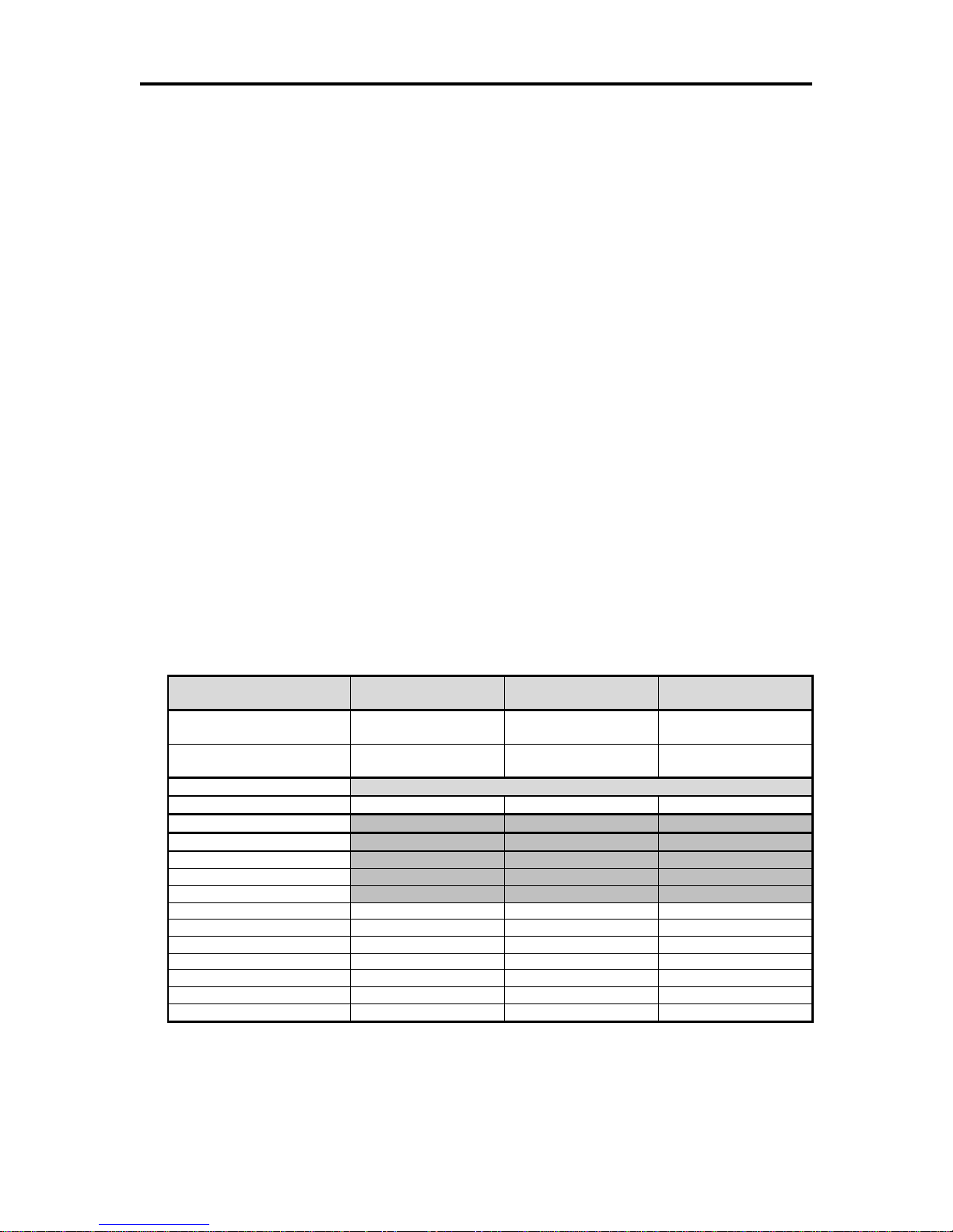
Character Pitch
The iTherm® 280 has 3 basic resident fonts, as well as downloadable fonts. The
smallest internal font is a 10 x 24 font and is typically printed in pitches from 16 to 20
characters per inch (CPI). The next larger font is 13 x 24, and is typically printed in
pitches from 14 to 16 CPI. The largest font is 15 x 24 and is typically printed in pitches
from 10 to 14 CPI.
The printer always prints at 203 dots per inch (dpi). Adding or subtracting space between
characters achieves different character pitches. As each dot has a fixed size and
position, only specific pitches are possible. The following table defines the fonts and
pitches possible with each.
NOTE: Shaded Pitches are not recommended.
Table 1 Possible Character Pitches
Page 14 Rev K
Page 27
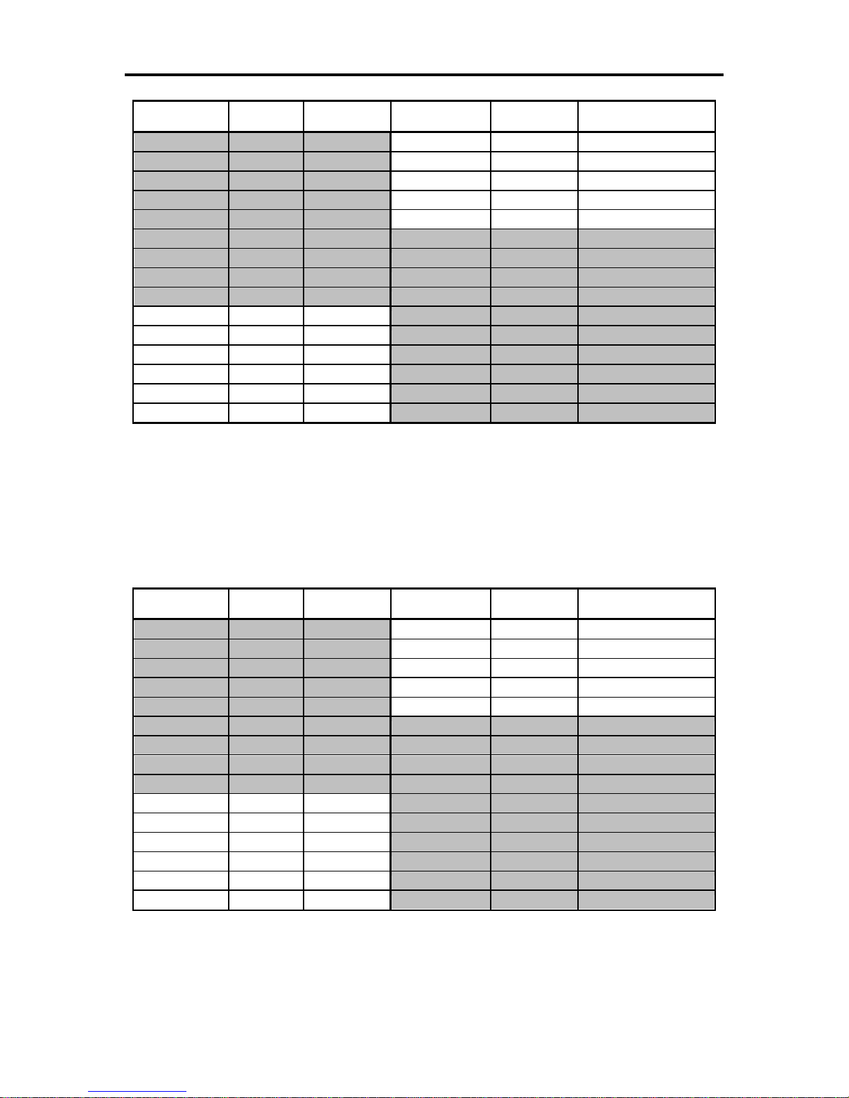
Specifications and Requirements iTherm® 280 Programmer’s Guide
Requested CPI
Character
Width
Resulting CPI
Requested CPI
Character
Width
Resulting CPI
1
203
1.00
16
12
16.92
2
101
2.01
17
12
18.45
3
67
3.03
18
11
18.45
4
50
4.06
19
10
20.30
5
40
5.08
20
10
20.30
6
33
6.15
21 9 22.56
7
29
7.00
22 9 22.56
8
25
8.12
23 8 25.38
9
22
9.23
24 8 25.38
10
20
10.15
25 8 25.38
11
18
11.28
26 7 29.00
12
16
12.69
27 7 29.00
13
15
13.53
28 7 29.00
14
14
14.50
29 7 29.00
15
13
15.62
30 6 33.83
Requested CPI
Character
Width
Resulting CPI
Requested CPI
Character
Width
Resulting CPI
1
203
1.00
16
12
16.92
2
101
2.01
17
12
18.45
3
67
3.03
18
11
18.45
4
50
4.06
19
10
20.30
5
40
5.08
20
10
20.30
6
33
6.15
21 9 22.56
7
29
7.00
22 9 22.56
8
25
8.12
23 8 25.38
9
22
9.23
24 8 25.38
10
20
10.15
25 8 25.38
11
18
11.28
26 7 29.00
12
16
12.69
27 7 29.00
13
15
13.53
28 7 29.00
14
14
14.50
29 7 29.00
15
13
15.62
30 6 33.83
NOTE: Shaded Pitches are not recommended.
Table 2 Requested CPI and Resulting CPI
Character Generation
Standard Print
There are three resident fonts in the printer: Small, Medium, and Large. The cell size for
each is different.
NOTE: Shaded Pitches are not recommended.
Table 3 Cell Size for Small, Medium and Large Fonts
28-04430 Rev K Page 15
Page 28

Specifications and Requirements iTherm® 280 Programmer’s Guide
Small 10 x 24 Font
The 10 x 24 small font is defined in a 10 x 24 cell. The characters are typically 22 dots
high and 8 dots wide; however to provide readable international characters, some
characters are wider. In most cases this font can be printed at 22.5 CPI without having
the characters touch. This font is recommended for printing from 16 to 20 CPI.
.
01 ...00.....
02 ..0000....
03 ..0000....
04 .00..00...
05 .00..00...
06 .00..00...
07 .00..00...
08 .00..00...
09 00....00..
10 00....00..
11 00....00..
12 00....00..
13 00....00..
14 00000000..
15 00000000..
16 00....00..
17 00....00..
18 00....00..
19 00....00..
20 00....00..
21 00....00..
22 00....00..
23 ..........
24 ..........
Medium 13 x 24 Font
The 13 x 24 medium font is defined in a 13 x 24 cell. The characters are typically 22 dots
high and 11 dots wide; however to provide readable international characters, some
characters are wider. In most cases this font can be printed at 16.9 CPI without having
the characters touch. This font is recommended for printing from 14 to 16 CPI.
01 ....000......
02 ....000......
03 ....000......
04 ...00.00.....
05 ...00.00.....
06 ...00.00.....
07 ...00.00.....
08 ..00...00....
09 ..00...00....
10 ..00...00....
11 ..00...00....
12 .00.....00...
13 .00.....00...
14 .00.....00...
15 .000000000...
16 .000000000...
17 00.......00..
18 00.......00..
19 00.......00..
20 00.......00..
21 00.......00..
22 00.......00..
23 .............
24 .............
Large 15x 24 Font
The 15 x 24 medium font is defined in a 15 x 24 cell. The characters are typically 22
dots high and 14 dots wide; however to provide readable international characters, some
characters are wider. In most cases this font can be printed at 13.5 CPI without having
the characters touch. This font is recommended for printing from 10 to 14 CPI. This font
is only available in the Ithaca emulation, and provides a bigger and darker character for
better readability.
Page 16 Rev K
Page 29

Specifications and Requirements iTherm® 280 Programmer’s Guide
01 .....0000......
02 ....000000.....
03 ....000000.....
04 ...000..000....
05 ...000..000....
06 ...000..000....
07 ...000..000....
08 ..000....000...
09 ..000....000...
10 ..000....000...
11 ..000....000...
12 .000......000..
13 .000......000..
14 .000......000..
15 .000000000000..
16 .000000000000..
17 000........000.
18 000........000.
19 000........000.
20 000........000.
21 000........000.
22 000........000.
23 ...............
24 ...............
Rotated Print
To provide printing flexibility, rotated print is available. Rotated print mode will rotate the
print in any of three 90 orientations. The individual characters can be rotated, or a
printer buffered mode is available. In printer buffered 90° and 270° rotated mode, the
print data is first buffered by the printer, processed (rotated), and then printed.
28-04430 Rev K Page 17
Page 30
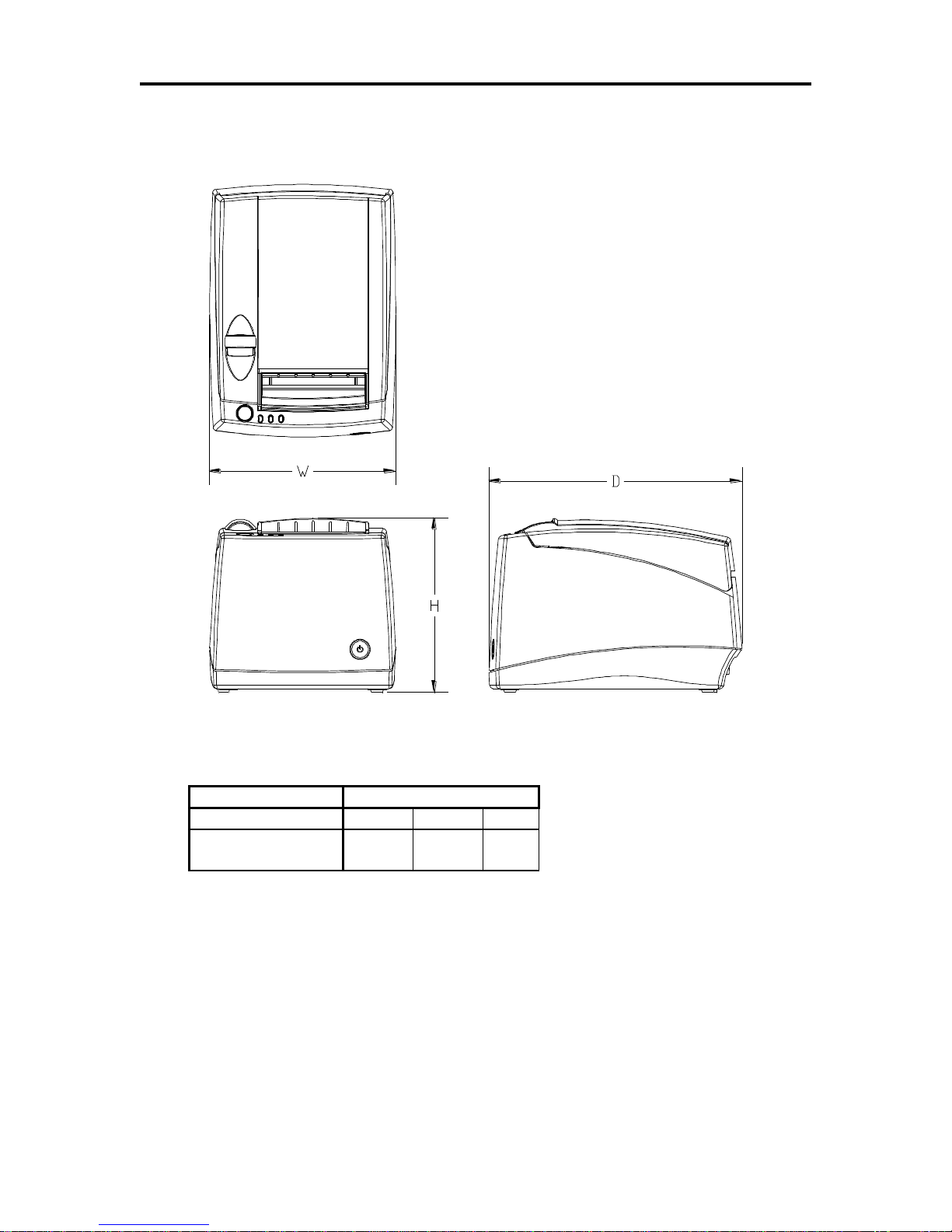
Specifications and Requirements iTherm® 280 Programmer’s Guide
Max Dimensions
W D H
Dimensions in
inches
6.25
8.50
5.87
Physical Characteristics
Dimensions
Weight
Approximate weight: 4.6 lb.
Shipping weight: 6.0 lb.
Page 18 Rev K
Page 31

Specifications and Requirements iTherm® 280 Programmer’s Guide
Supply
Voltage
Rating
(VAC)
Supply
Voltage
Range
(VAC)
Frequency
(Hz)
Rated Power
(watts)
Idle Current
(amps)
Printing Current
(amps)
100-240
90-264
47 – 63
45
.1A @ 120VAC
.05 A @ 240VAC
1.4 A @ 120VAC
.7 A @ 240VAC
Supply
Voltage
Rating
(VDC)
Supply
Voltage
Range
(VDC)
Frequency (Hz)
Idle
Current
(amps)
Current (amps)
24
-5+10%
22.8 –
26.42
DC
0.125 A 2.0 A (Cash Drawer Fire)
3.5 A (Printing maximum for < 1 minute)
4.8 A Peak (< 167 msec.)
Number of heat elements:
640
Heat element pitch:
0.125 mm (8 dots/mm.)
Print width:
80 mm. +/- 0.2 mm.
Pulse Life:
100 million pulses
Abrasion Life:
100 km.
Vertical dot pitch
0.264 mm (0.0104 inch) or 96 DPI
Operating Temperature
5-45 degrees C
Humidity:
10-90 % RH (non-condensing)
Electrical Characteristics
Internal AC Powered
The iTherm® 280 Printer is designed to be AC self-powered in domestic and
international markets. The printer is equipped with a universal input power supply that is
designed to operate worldwide without modification.
Table 4 Standard Power Input Requirements
External Powered DC
Optionally, the iTherm® 280 Printer can be operated with 24-volt DC power supplied
from a host terminal or external supply. Connection to this printer version is made via a
three-pin Hosiden type connector.
Table 5 Power Input Requirements with the 24-volt DC Power
The iTherm® 280 can be configured to operate with various power supplies. If a DC
power supply with less capability is used, the printer must be configured for reduced
power and the printer will print slower.
Thermal Print Head
Thermal Print Head Overview:
Operation Precautions:
Do not print without paper.
Clean the head with ethyl-alcohol after power is removed from the printer. This will
remove foreign particles or paper dust which may degrade print quality.
Be sure to set the paper width in the printer‘s configuration to agree with the paper
being used (58 or 80 mm width).
2
For DC powered printers, the cash drawer is supplied directly from the DC input supply. The
cash drawer requirements may affect the allowable range of voltages.
28-04430 Rev K Page 19
Page 32

Specifications and Requirements iTherm® 280 Programmer’s Guide
Paper
Manufacturer
Kanzaki P-300
Kanzaki P-310
Appleton Alpha 400-2.3
Basis Weight
14.1 lbs.
14.2 lbs.
14.5 lbs.
Caliper
.00225 mils
.00226 mils
.00235 inches
Image color
black
Black
Black
Brightness
85%
85%
87%
Activation Temp.
Initial: 74+/-5°C
Effective: 87 +/- 5°C
Optimum: 100 +/- 5°C
Initial:73 +/-5°C
Effective: 83 +/- 5°C
Optimum: 88 +/- 5°C
Initial:77.2°C
Optimum: 104.8 +/- 5°C
Smoothness (bekk)
325 sec. Ave.
325 sec.Ave.
200 (bekk).
Paper
Manufacturer
Kanzaki P-320 RB
Kanzaki P-320 BB
Appleton Dual RB
Appleton Dual BB
Basis Weight
14.6 lbs.
14.6 lbs.
15.6 lbs.
15.6 lbs.
Caliper
.00227 mils
.00227 mils
.00235 mils
.00235 mils
Brightness
87 %
87 %
89.5 %
87.8 %
Image color
Red/Black:
Blue/Black
Red/Black:
Blue/Black
Thermal
Response
Initial(Red):80 +/-5°C
Initial(B):98 +/-5°C
Effective(Red): 87 +/- 5°C
Effective(B): 116 +/- 5°C
Optimum(Red):100 +/-5°C
Optimum(B):130 +/-5°C
Initial(Blue):74 +/-5°C
Initial(B):90 +/-5°C
Effective(Blue): 80 +/- 5°C
Effective(B): 120 +/- 5°C
Optimum(Blue):90 +/-5°C
Optimum(B):130 +/-5°C
Initial(Red):77.8 +/-5°C
Initial(B):77.8 +/-5°C
Optimum(Red):90.5 +/-5°C
Optimum(B):103.3 +/-5°C
Initial(Blue):69.4 +/-5°C
Initial(B):69.4 +/-5°C
Optimum(Blue):82 +/-5°C
Optimum(B):118 +/-5°C
Smoothness
(bekk)
500 sec. ave.
500 sec. ave.
250 sec./min.
250 sec./min.
Once narrow paper has been used, some part of the print head always contacts the
platen. If 80 mm. paper is used after setting up and running 58 mm. paper, the head
or the cutter blade may be worn out. Never change the paper width from narrow to
wide (58 to 80 mm.) once you set the paper width to narrow (58 mm.).
Media Specifications
Receipt Paper
Paper feed method Friction feed
Paper feed pitch Default - 1/8 inch
Paper width 80 mm: 79.5 +/- 0.5 mm. (3.13 +/- 0.02 inches)
58 mm: 57.5 +/- 0.5 (2.26 +/- 0.02 inches)
Roll diameter 101.6 mm. (4.0 inches) Max.
Paper thickness 0.06 to 0.09 mm. (.00225 to .0035 inches)
Roll paper core Inside diameter .445 to .635 inches
Outside diameter .730 to .860 inches
Roll footage 400 feet (min.)
Thermal Paper Grades (Monochrome)
Table 6: Paper Grades-Monochrome
Thermal Paper Grades (color)
Table 8: Paper Grades-Color
Paper Usage Precautions:
The life of the thermal head, when two-color paper is used, is reduced to half of the
life when single-color thermal paper is used.
Page 20 Rev K
Page 33

Specifications and Requirements iTherm® 280 Programmer’s Guide
Paper Low Adjustment Settings
Approximate Paper Remaining
(in feet)
Paper Roll Diameter
UPPER LIMIT: 2 turns (counter clockwise)
29‘
1.29"
1 turn (counter clockwise)
23‘
1.203"
FACTORY SETTING
18'
1.115"
1 turn (clockwise)
13'
1.028"
LOW LIMIT: 2 turns (clockwise)
8.5‗
.940―
1.00”
2.83
3.15
0.15
Use only specified thermal paper. If other paper is used, print quality, head life, and
cutter life may deteriorate.
Paper Out
A receipt paper out sensor is provided as a standard feature. It senses when there is
approximately .5 inches length of paper left on the paper roll.
Paper Low
A receipt paper-low sensor is provided as an optional feature. An operator adjustable
paper-low assembly will be provided to allow the printer to sense when the paper roll
diameter is between .94 to 1.29 inches (approximate). It is adjustable to compensate for
various paper core dimensions.
Notes:
These measurements are approximate. Paper roll used for testing had paper roll
core outside diameter of .750 inches, and inside diameter is .625 inches. Results will
vary depending on core O.D./I.D. dimensions.
Paper roll core should meet or exceed paper width.
Results based on thermal paper .0025 inches thick.
The receipt printable area is as shown in the following diagram.
Figure 1 Receipt Printing, Tear off Position
The paper tear off is positioned 1 inch from the last line of print
28-04430 Rev K Page 21
Page 34

Specifications and Requirements iTherm® 280 Programmer’s Guide
Receipt Printing, Auto Cutter Position
A receipt auto-cutter is a standard feature with all iTherm™ 280 Printers.
Cutter type Rotary
Media width 3.13 +/- .02 inches (79.5 +/- .5 mm)
Media thickness range 0.0025 to 0.0035 inch
Cut to line of print 0.70 inch
Cutter life 1,000,000 cuts
Partial Cut tab: .125 inches +/- .0625 inches (right edge of receipt)
Cut time: Less than 350 milliseconds
Buzzer
A buzzer is provided as a standard feature. It is triggered upon command from the host
terminal to make a sound loud enough to be heard under noisy conditions. It will produce
a sound pressure level of at least 90 dBA, 1 foot from the front of the printer.
Cover Interlock
A paper cover interlock switch is provided as a standard feature. When the paper cover
is open, the printer is off-line, and will not print.
Display Pass Through
The display pass through feature allows a pole display to be interconnected with the
printer. The printer is connected to a host system with a special serial cable. The host
sends serial data to the printer and the printer sends serial data to the pole display. The
printer does not provide power to the display. During normal printer operation, no data is
passed to the display. In pass through mode, all received data is passed on to the
display.
Page 22 Rev K
Page 35

Specifications and Requirements iTherm® 280 Programmer’s Guide
25-pin Connector
36-pin
Connector
Signal
Description
Direction
Pin 1
Pin 1
STROBE
Clock data to printer
Host to Printer
Pins 2-9
Pins 2-9
D0 - D7
Data
Host to Printer
Pin 10
Pin 10
ACK\
Printer accepted data
Printer to Host
Pin 11
Pin 11
BUSY
Printer busy
Printer to Host
Pin 12
Pin 12
PE
Paper Out/Status
Printer to Host
Pin 13
Pin 13
SLCT
Printer selected
Printer to Host
Pin 14
Pin 14
AUTOFD
Autofeed paper
Host to Printer
Pin 15
Pin 32
FAULT\
Printer error
Printer to Host
Pin 16
Pin 31
INIT\
Initialize printer
Host to Printer
Pin 17
Pin 36
SLIN
Select printer
Host to Printer
Pin 17
FG
Frame ground
Printer to Host
-
Pin 18
+5V
Peripheral logic high
Printer to Host
Pins 18-25
Pins 16, 19-30
GND
Ground
Communications Interface
Parallel Interface
Your printer features two parallel interfaces:
An IEEE 1284-A 25-pin, D-shell connector, with pin-outs that interface to a
standard IBM PC parallel printer interface with a one-to-one cable.
An IEEE 1284-B, which is a standard Centronics 36-pin connector.
Both interface cards provide a dual cash drawer interface. The following table lists
interface signals and corresponding pins.
Table 7 Parallel Interface Pin-outs
Signal Levels
Voltage levels 0 V and +5 V (nominal)
Logic levels
Logic one
Driver +2.4 V to +5 V
Receiver +2.0 V to +5 V
Logic zero
Driver 0 V to +0.4 V
Receiver 0 V to +0.8 V
Current requirements
Logic one Source 0.25 ma at +2.4 V
Logic zero Sink 16 ma
Line termination
Data and control 3.3k ohm to +5 V
Strobe 1.2k ohm to +5 V
28-04430 Rev K Page 23
Page 36

Specifications and Requirements iTherm® 280 Programmer’s Guide
9-pin
25-pin
Signal
Description
Pin 1
Pin 8
Not Connected
Pin 2
Pin 3
RX
Receive Data
Pin 3
Pin 2
TX
Transmit Data
Pin 4
Pin 20
DTR
Data Terminal Ready
Pin 5
Pin 7
GND
Signal Ground
Pin 6
Pin 6
DSR
Data Set Ready
Pin 7
Pin 4
RTS
Request to Send
Pin 8
Pin 5
CTS
Clear to Send
Pin 9
Pin 11
Not Connected
RS-232 Serial Interface
Serial Port Features
The serial port features are as follows:
Baud Rates 300, 600, 1200, 2400, 4800, 9600, 19.2K, 38.4K, and 57.6K
Bit Patterns 8-bit no parity; 8-bit odd; 8-bit even; 7-bit no parity; 7-bit odd; 7-bit even
Flow Control DTR and XON/XOFF
Table 8 Serial Interface Pin-outs
Signal Voltage and Current levels
The serial interface meets EIA RS232 interface specifications:
Voltage Levels Max +-15 Volts
Min +- 3 Volts
Mark = Off = -3 to –15 Volts
Space = On = +3 to +15 Volts
Because both the host and printer are DTE's (Data Terminal Equipment), they use the
same serial port pin-outs. If the cable that is used to connect the host to the printer is a
pin-to-pin inter-connect, it will not work. Therefore, a null modem or turn-around cable
must be used to interconnect the host and the printer.
Display Pass Through
The display pass through feature allows a pole display to be interconnected with the
printer. The printer is connected to a host system with a special serial cable. The host
sends serial data to the printer and the printer sends serial data to the pole display. The
printer does not provide power to the display. During normal printer operation, no data is
passed to the display. In pass through mode, all received data is passed on to the
display.
USB Interface
The USB interface is a Version 1.1 interface that is Version 2.0 compliant. The standard
USB interface card is implemented through a Standard Series "B" Receptacle as defined
in the USB Specification. The printer is self-powered and does not draw power from the
standard type B USB interface cable.
The Standard USB Type B connector has the following pin functions:
Page 24 Rev K
Page 37

Specifications and Requirements iTherm® 280 Programmer’s Guide
Note: The standard USB interface does not have enough power to run the
printer.
Note: The Ethernet adapter supports only the Ithaca Cash Drawer
interface.
Pin Signal
1 Vbus (+5 V dc) (Not used in the iTherm® 280)
2 Minus data
3 Plus data
4 Ground
Ethernet 10-Base-T adapter
An IP addressable 10-Base-T Ethernet adapter is available for the iTherm® 280 printer.
It provides for web page configuration and supports bi-directional RAW and Telnet
interfaces. All protocols are implemented to the extent necessary to support printing
from Windows™ platforms; specific protocols supported include the following:
Line Printer Daemon Protocol (LPR) – RFC1179
Simple Network Management Protocol (SNMP) – RFC1157
Printer MIB – RFC1759
Port 9100 (Raw data)
Service Location Protocol (SLP) – RFC2165
The TFTP Protocol (Revision 2) – RFC1350
Telnet COM Port Control Option – RFC2217
Hypertext Transfer Protocol – HTTP/1.1 – RFC2616
Refer to the 100-05072 Wired Ethernet Programmer‘s Guide for features and additional
setup information.
802.11b Wireless Interface
An 802.11b wireless interface is available for the iTherm® 280 printer, allowing wireless
operation of the printer within a specified distance of a base unit. Contact TransAct
technical support for more information on this interface.
28-04430 Rev K Page 25
Page 38

Specifications and Requirements iTherm® 280 Programmer’s Guide
pin 1 CD2-
pin 2 CD1 Sense
pin 3 Ground
pin 4 CD Drive + (+24V)
pin 5 CD1-
pin 6 Not Connected
pin 1 Not Connected
pin 2 CD1-
pin 3 CD1 Sense
pin 4 CD Drive + (+24V)
pin 5 CD2-
pin 6 Ground
pin 1 Not Connected
pin 2 CD1-
pin 3 CD Drive + (+24V)
pin 4 CD Drive + (+24V)
pin 5 CD2-
pin 6 CD1 Sense
Ithaca Epson Star
Cash Drawer
Interface Description
The iTherm® 280 Printer supports a single cash drawer with status. The driver in the
printer is capable of supplying 24 V DC at up to 1.5 amps for up to 250 milliseconds. The
iTherm® 280 Printer defines cash drawer closed as switch open. If the drawer is
disconnected, it will be viewed by the printer as closed. Since the printer does not act on
the cash drawer status, the application can interpret cash drawer status any way it
wants.
Driver connector type (standard) Single RJ12 connectors with 24V sink drivers
Driver voltage 24 volts (Refer to power supply specification).
Driver current 1 amp maximum with current limit
Pulse duration 250 msec. maximum
Drawer status Open/close drawer status provided to printer
Cash Drawer Pin Assignments
Figure 2 Cash Drawer Pin Definitions
The cash drawer can be configured for one of three configurations; Ithaca, Epson, or
Star. The Main Controller PCB has three (3) six-pin headers, one each configuration.
The cash drawer harness is identical, and is plugged into the appropriate header at time
of factory build. The header position defines the configuration of the cash drawer. This
design allows for changing the cash drawer in the field by a trained technician. Refer to
the markups on the board when determining where the harness should be installed to
work in the three different configurations.
Page 26 Rev K
Page 39

Specifications and Requirements iTherm® 280 Programmer’s Guide
Pin Number
Ithaca®
Epson (Standard)
Star
Signal Name
pin 1 CD2-
pin 2 CD1 Sense
pin 3 Ground
pin 4 CD Drive +(+24V)
pin 5 CD1-
pin 6 Not Connected
Direction
Signal Name
pin 1 Not Connected
pin 2 CD1-
pin 3 CD1 Sense
pin 4 CD Drive + (+24V)
pin 5 CD2-
pin 6 Ground
Direction
Signal Name
pin 1 Not Connected
pin 2 CD1-
pin 3 CD Drive +(+24V)
pin 4 CD Drive +(+24V)
pin 5 CD2-
pin 6 CD1 Sense
Direction
1
Drawer 2 kick out drive
signal
Output
Sink
Drive
Not Connected
Not Connected
2 Drawer 1 open/close signal
Input
Drawer 1 kick out drive
signal
Output
Sink
Drive
Drawer 1 kick out drive
signal
Output
Sink
Drive
3
Signal Ground
Drawer 1 open/close signal
Input
+24V DC
4 +24V DC
+24V DC
+24V DC
5
Drawer 1 kick-out drive
signal
Output
Sink
Drive
Drawer 2 kick out drive
signal
Output
Sink
Drive
Drawer 2 kick out drive
signal
Output
Sink
Drive
6
Not Connected
Signal Ground
Drawer 1 open/close
signal
Input
Table 9 Cash Drawer Pin Assignment
28-04430 Rev K Page 27
Page 40

Specifications and Requirements iTherm® 280 Programmer’s Guide
Vertical Wall Mount Kit Option
A kit is available as an add-on option that allows the iTherm® 280 printer to be vertically
mounted to a wall. It is comprised of a metal mounting bracket that attaches to the base
of the printer with two M6 thread-cutting screws. Additional hardware is required to
mount the bracket to the wall. The hardware should be installed into wall studs to
ensure that the printer mounting meets the following conditions:
The mounting to the wall must withstand 4 times the printer weight in downward and
outward directions.
The kit must include mounting instructions to explain how to meet the load test
The firewall or the outer housing of the printer is maintained between the controller
PCB and the mounting wall.
Page 28 Rev K
Page 41

chapter 3
Setup Procedures
28-04430 Rev K Page 29
Page 42

Page 30 Rev K
Page 43

Setup Procedures iTherm® 280 Programmer’s Guide
Verifying the Configuration
Before you install an iTherm® 280 Printer into your system, you should verify that the printer is
configured as required by your system. There are four parts to this verification process.
1. Verify that the communications interface card is the correct one.
2. Verify that the cash drawer interface is configured correctly.
3. Verify that the power connection is correct.
4. Verify that the firmware in the printer is configured correctly.
Verify the Communications Interface Card
There are several basic types of interface cards, and each has variations. Make sure your
printer has the correct interface card.
Parallel Interface
Centronics 36-pin interface
25-pin D shell
Serial Interface
9-pin D shell interface
25-pin D shell interface
USB Interface
Standard 4-pin
Ethernet 10-Base-T Adapter
Standard Ethernet port connector
802.11b Wireless Interface
Wireless interface pre-installed within printer unit
It is easy to distinguish most of the interface cards other than the 25-pin serial and 25-pin
parallel interface cards. To determine what interface is installed, refer to the configuration
receipt shipped with the printer, or enter configuration mode and look at the verification printout.
If a serial interface card is installed, the printout will refer to the RS-232 serial interface. If the
parallel interface card is installed, the printout will refer to the parallel interface.
Changing Interface Cards
The interface card on the iTherm® 280 Printer can be changed in the field.
In most cases, interface cards are interchangeable without altering the printer firmware.
However, you may have to load new firmware and/or a new boot loader before you change the
interface cards. Check with Technical Support for firmware compatibility between interface
cards before ordering.
Removing the Old Interface Card
1. Turn over the printer, taking care not to allow the cover to open or the paper to fall.
2. Disconnect the current communications and cash drawer cables.
3. If equipped, unsnap the power supply retainer and slide out the power supply.
4. Disconnect the power supply from the interface card.
5. Remove the interface retaining screw.
6. Slide the interface card sideways-towards the power supply pocket-and remove it.
28-04430 Rev K Page 31
Page 44

Setup Procedures iTherm® 280 Programmer’s Guide
Cash Drawer Configuration
Verify the Cash Drawer Interface
The printer is shipped from the factory with a cash drawer interface label on the bottom of the
printer. You should always verify that the cash drawer you are using matches the printer‘s cash
drawer interface label. If there is no cash drawer label, you should remove the communications
interface card and verify the setting. See "Configuring the Cash Drawer Interface" on page 32 .
There are many vendors of cash drawers. If you are unsure what the cash drawer interface is,
contact the cash drawer vendor for more information.
If you find that the cash drawer does not match the printer, you may change the printer's cash
drawer interface configuration. If the cash drawer interface no longer matches the label on the
printer, please remove the label.
Install the new interface card
1. Slide the interface card into the printer. Make sure the interface card sits flush with the
printer. The retaining screws should also line up with the mounting holes.
2. Install the retaining screws.
3. Connect the communications interface card and any cash drawer cables.
4. Turn over the printer, and reconnect the power.
Configuring the Cash Drawer Interface
CD interface drawing not yet available.
Figure 3 Cash Drawer Selection
The cash drawer connector may be connected to one of three internal connectors on the
controller board. To access the internal connector, you must first remove the interface adapter.
Removing the interface card
1. Unplug the printer
2. Turn over the printer. Take care not to allow the cover to open or the paper to fall.
3. Disconnect the current communications and cash drawer cables.
4. Remove the interface retaining screw2.
5. Slide the interface card towards the back of the printer and remove it.
Reconfigure the cash drawer
1. Slide the cash drawer socket out of the slot in the frame.
2. Unplug the socket harness from the main circuit board.
3. Plug the harness into the connector for the desired interface.
4. Reinstall the cash drawer socket into the frame.
Re-Install the interface card
1. Slide the interface card into the printer. Make sure the interface card sits flush with the
printer. The retaining screws should also line up with the mounting holes.
2. Install the retaining screws.
3. Connect the communications interface card and any cash drawer cables.
4. Turn over the printer, and reconnect the power.
Page 32 Rev K
Page 45

Setup Procedures iTherm® 280 Programmer’s Guide
3) Cash Drawer/
External Buzzer
2) Communications
1) DC Power
Power Pocket®
Installing Cables
Figure 4 Power and Communications Ports
Three cables are required to be connected to the printer.
1. DC Power
2. Communications
3. Cash Drawer
Connecting power
The iTherm® 280 Printer is generally supplied with a built-in power supply. As an option, the
printer is available without a power supply.
Internal Supply
The internal supply connects to an outside power source with a standard two wire power cord.
28-04430 Rev K Page 33
Page 46

Setup Procedures iTherm® 280 Programmer’s Guide
Earth Ground
+24 Volt Supply
Ground (+24 V dc)
9-pin
25-pin
Signal
Description
Pin 2
Pin 3
RX
Receive Data
Pin 3
Pin 2
TX
Transmit Data
Pin 4
Pin 20
DTR
Data Terminal Ready
Pin 5
Pin 7
GND
Signal Ground
Pin 6
Pin 6
DSR
Data Set Ready
Pin 7
Pin 4
RTS
Request to Send
Pin 8
Pin 5
CTS
Clear to Send
25-pin
Connector
36-pin
Connector
Signal
Description
Direction
Pin 1
Pin 1
STROBE
Clock data to printer
Host to Printer
Pins 2-9
Pins 2-9
D0 - D7
Data
Host to Printer
Pin 10
Pin 10
ACK\
Printer accepted data
Printer to Host
Pin 11
Pin 11
BUSY
Printer busy
Printer to Host
Pin 12
Pin 12
PE
Paper Out/Status
Printer to Host
Pin 13
Pin 13
SLCT
Printer selected
Printer to Host
Pin 14
Pin 14
AUTOFD
Auto-feed paper
Host to Printer
Pin 15
Pin 32
FAULT\
Printer error
Printer to Host
Pin 16
Pin 31
INIT\
Initialize printer
Host to Printer
Pin 17
Pin 36
SLIN
Select printer
Host to Printer
Pin 17
FG
Frame ground
Printer to Host
-
Pin 18
+5V
Peripheral logic high
Printer to Host
Pins 18-25
Pins 16, 19-30
GND
Ground
External Supply
If an external supply is used a 3 pin mini DIN plug is provided for the external 24 Volt supply.
Figure 5 3-pin mini DIN plug
Connecting Communications Cables
The iTherm® 280 has a number of different communications interfaces.
Serial
The serial interface connector is either a 9-pin or 25-pin mail D shell interface. The pin-out is
shown below
Table 10 Serial interface pin out
Parallel
The parallel interface connection is very similar to the serial interface connection. It can be a
36-pin Centronics (IEEE 1284-B) or a 25-Pin female D-Shell (IEEE 1284-A) connector. The pinout of both connectors are shown below
Table 11 Parallel interface pin out
Page 34 Rev K
Page 47

Setup Procedures iTherm® 280 Programmer’s Guide
USB
The USB connector can be one of two types: a standard Type B connector, as in commonly
used in the PC industry, or a POS Powered USB connector. In the case of the powered USB
connector, there are a number of different versions. Make sure you are using a 24 volt DC
version, and the 24 volt supply meets the requirements of the iTherm® 280 printer and any cash
drawer that is connected to the printer.
A powered USB interface is a special order option. There are several standards for the power
interface. Make sure that you inform TransAct is aware of what interface you require, and that
that interface connector is supported by the iTherm® 280.
Verify the Firmware Configuration
An example receipt is Included in the box your printer shipped in that will show how the printer
was configured before it shipped from our Ithaca facility. Compare this information to your
system requirements. Pay attention to the emulation and the communications link. If they are
wrong, the printer may appear inoperative. If the configuration is not correct, refer to the section
on changing the iTherm® 280 configuration. If there are a number of printers to be installed and
you want the identical configuration in each, you can use the universal configuration program to
record the configuration on one printer, and replicate it over a group. The configuration program
is available from Transact technical support.
Installing Paper
It is easy to install paper in the iTherm® 280.
1. Open the paper cover by grasping the green cover release between your thumb and
forefinger, and squeeze the release. This will pop the cover up.
2. Open the cover and install a roll of paper with the paper coming off of the bottom of the
roll.
3. Lay the paper tail over the front of the printer and center it over the paper path.
4. Close the cover. When the cover is closed, the printer will feed several inches of paper
to make sure the paper is aligned in the printer. If equipped with a cutter, the printer will
automatically cut the paper tail and the printer is now ready to print. If the printer is not
equipped with a cutter, the operator should remove the paper tail.
28-04430 Rev K Page 35
Page 48

Setup Procedures iTherm® 280 Programmer’s Guide
Installing Windows® Printer Drivers
Printer Driver Installation for WIN95, 98, Me
1. Insert the ―Windows 95, 98, Me printer driver‖ disk into your diskette drive.
2. Click on ―Start‖ menu -> ―Settings‖ -> ―Printers‖.
3. Double Click on ―Add Printer‖ Icon.
4. Select ―Next‖.
5. Select ―Local printer‖ and ―Next‖.
6. Click on ―Have Disk‖. If your floppy is A: use A:\ and then ―OK‖.
7. Select the printer you have (i.e. Series iTherm® 280) and then ―Next‖.
8. If you are asked ―Keep existing driver‖ or ―Replace existing driver‖. Choose
―Replace existing driver‖ and then ―Next‖.
9. Select the port the printer is connected to, and then ―Next‖.
10. Select ―Yes‖ or No‖ for default printer, Printer name should not be altered, so
choose ―Next‖.
11. If you wish, you can print a test page. Due to the narrow paper stock that this
printer uses, and the margins Windows chooses, there will not be enough room
to print all the images of the test page. Some of the large text will word-wrap and
be truncated.
12. Select ―Finish‖. The printer driver is now installed.
13. If you selected ―Replace existing driver‖, reboot your machine to ensure all
components are installed.
Printer Driver Installation for NT4.0, 2000
1. Insert the ―Windows NT, 2000 printer driver‖ floppy disk into your diskette drive.
2. Click on ―Start‖ menu -> ―Settings‖ -> ―Printers‖.
3. Double-click on the ―Add Printer‖ Icon.
4. Select ―My Computer‖ and ―Next‖.
5. Select the port the printer will be connected to, and then ―Next‖.
6. Click on ―Have Disk‖. If your floppy is A: use A:\ and then ―OK‖.
7. Select the printer you have (i.e. Series iTherm® 280) and then ―Next‖.
8. If you are asked ―Keep existing driver‖ or ―Replace existing driver‖. Choose
―Replace existing driver‖ and then ―Next‖.
9. Printer name should not be altered, so choose ―Next‖.
10. Select ―Not Shared‖ ―Next‖.
11. If you wish, you can print a test page. Due to the narrow paper stock that this
printer uses, and the margins Windows chooses, there will not be enough room
to print all the images of the test page. Some of the large text will word wrap and
be truncated.
12. Select ―Finish‖. The printer driver is now installed.
13. If you selected ―Replace existing driver‖, reboot your machine to ensure all
components are installed.
Page 36 Rev K
Page 49

Setup Procedures iTherm® 280 Programmer’s Guide
OPOS drivers Installation Instructions
1. Run Setup OPOS.exe.
2. The communications will be defaulted to ―COM2‖. If the communication port is
not setup at installation, the first time the printer service object Open method is
called, a Com port setup dialog will be displayed.
3. After running Setup.exe there will be an OPOS setup utility in the OPOS program
group/start menu, and also in the Windows Control Panel. Use this utility to set
up the OPOS printer ―driver‖ and cash drawer ―driver‖.
To Install the USB drivers
1. Ensure that USB is enabled in your system's BIOS. To verify that USB is
enabled, click on "Start", "Settings", "Control Panel". Double click "System" and
select the "Device Manager". If you see "Universal Serial Bus controllers" in the
list, USB is enabled. Check you PC's documentation for more information about
USB if needed.
2. Ensure that power is applied to the printer and plug in the USB cable to both the
PC and printer.
3. Follow the on screen directions. Please note that several drivers are installed in
this process. Therefore the "Found new hardware" prompt will appear several
times. If the system needs a file, direct it to the location of the USB driver install
disk (usually the floppy drive).
See ―readme.txt‖ or ―usbman.htm‖ on the install disk for more information.
28-04430 Rev K Page 37
Page 50

Page 51

chapter 4
How to Operate the iTherm® 280 Printer
28-04430 Rev K Page 39
Page 52

Page 40 Rev K
Page 53

How to Operate the ITherm® 280 iTherm® 280 Programmer’s Guide
How to Operate the iTherm® 280 Printer
Your iTherm® 280 printer contains two buttons and three (LED) indicator lights. In
addition to power control and feeding paper, these two buttons can be used to perform
functions like self-testing, clearing errors and printer configuration. They are:
* BUTTON This is the standby or power down button, located on front face of the
printer‘s cabinet
FEED Located on bottom portion of printer‘s keypad
* Button
The iTherm® 280 has been designed to remain connected to a power source at all times.
The * button on the iTherm® 280 Printer does not completely remove power from the
printer. Because of this, the * button is used to alternately switch the printer between
OFF and ON modes. The * button does not disconnect power to the printer. The printer
is truly off only when the AC power supply is disconnected. You will notice that none of
the indicator lights will be on when the printer is in OFF. When the printer enters ON
mode, the green power indicator light will be activated. The operational state of the
iTherm® 280 can be determined by looking at the Power Indicator Light (LED).
When the * button is pressed or the power down command is received, the iTherm® 280
Printer enters an OFF low power mode. The printer is not completely off, but is in
Standby mode 3.
Standby mode is remembered even if the power is removed. Whenever power is turned
back on, the printer starts, performs Level 0 diagnostics, and re-enters Standby mode.
FEED Button
The FEED button feeds paper through the printer. By pressing the FEED button
momentarily, the paper will be fed one line at a time. Pressing and holding the FEED
button will make the printer feed paper continuously until the button is released.
3
The printer draws about four watts of power in Standby.
28-04430 Rev K Page 41
Page 54

How to Operate the ITherm® 280 iTherm® 280 Programmer’s Guide
Indicator Lights (LED)
The three iTherm® 280 indicator lights are:
Power LED Indicates printer activity and non-recoverable errors
Error LED Indicates problems and probability of recovery
Paper LED Indicates paper status (paper low)
Power Indicator (LED)
The power indicator lets the user know that the printer is ON. If the POWER indicator
blinks in conjunction with the ERROR indicator, the printer is experiencing a nonrecoverable error: see the fault indicators discussed below. If the POWER indicator blinks
and there is no error indicator blinking, the printer is being held in reset by the host.
Error Indicator (LED)
The ERROR indicator lets the user know that the printer is experiencing a problem. If the
POWER indicator is lit (not blinking), the error is generally recoverable without data loss.
If the POWER indicator is blinking, a non-recoverable error has occurred: see the fault
indicators below. If the error is not operator recoverable, a power cycle may correct the
problem. If a power cycle does not correct the fault, the printer must be serviced.
Paper Indicator (LED)
The PAPER indicator signals the paper status. If the printer is equipped with a paper low
option, the PAPER indicator will blink when the paper is low. The low sensor is adjustable,
and the amount of paper remaining is dependent on the adjustment. If the PAPER
indicator is lit with the error indicator, the printer is out of paper: in this case, the printer
stops printing and waits for the paper to be changed.
Fault Indicators
The ERROR indicator is the primary fault indicator, and is either always on or blinking if a
fault has occurred. There are three types of faults:
Fully-recoverable faults Paper out or cover open
Semi-recoverable faults Head jam
Non-recoverable faults Component failure
Page 42 Rev K
Page 55

How to Operate the ITherm® 280 iTherm® 280 Programmer’s Guide
Error Indicated
Blink Count
Unused
1
Configuration Read
2
Configuration Write
3
Software Error
4
Auto Cutter Error
5
Unused
6
User Store Format Error
7
Electronic Journal Format Error
8
Flash Operation Error
9
Internal Memory Error
12
Communication Adapter Error
14
Operating System Error
15
Fully-recoverable and Status
A fully-recoverable error will restart printing exactly where it stopped when the error
occurred. Printing will resume after error has been properly addressed. A status
recoverable error is very similar to a fully-recoverable error. Additionally, status is used
to display when the printer consumables may need replacing.
Semi-recoverable
A semi-recoverable error is determined by whether or not the printer has to be shut off
and turned back on while attending to the problem. The amount of information lost is
dependent on the type of error and the state of the information being processed.
Non-recoverable
A non-recoverable error produces information loss.
Error Blink Codes
If during normal operation, the ERROR indicator is lit and the POWER indicator is blinking,
a minor error occurred. The POWER indicator shows the error by blinking a pattern.
Cycling the power restarts the printer. Blink patterns are defined as follows.
1 Blink (1 blink, pause)
__█__________________█______
2 Blink (2 blinks, pause)
__█__█_______________█__█___
3 Blink (3 blinks pause)
__█__█__█____________█__█__█_
A similar pattern is followed for other blink counts. Error indications are as follows:
Table 12 Error Blink Codes
28-04430 Rev K Page 43
Page 56

How to Operate the ITherm® 280 iTherm® 280 Programmer’s Guide
Testing the Printer Overview
Using Self-Test, Configuration, and Hex Dump Mode
Self-Test Mode allows you to perform a series of tests to show if the printer is functioning
correctly. Self-Test Mode also allows you to print a summary of how your iTherm® 280 is
currently configured. Use this printout to compare your printer‘s settings to your system‘s
requirements. Specific attention should be given to emulation and communications
settings. For serial printers, the baud rate and other RS-232 interface settings are
important. If there is a configuration problem, you should use Configuration Mode to
make any changes necessary.
Entering Self-Test, and Configuration mode
To enter self test and or configuration mode, perform the following sequence of
operations:
1. Press and release the * button to turn the printer OFF. (The power indicator light
will be off.)
2. Press and hold the Feed button.
3. While holding the Feed button, press and release the * button.
4. When the red, error indicator light blinks, release the Feed button
5. Follow the directions printed on the receipt to cycle through and select the
desired TEST option.
The iTherm® 280 has a total of seven Self-Test and or configuration options. Two are
designed to be useful when performing on-site print evaluations. One option allows the
printers electronic journal to be maintained, one allows the printers configuration to be
changed, and two are designed for factory setup by TransAct.
Testing the printer
Use the following two TEST options when verifying basic printer operation.
TEST-Receipt
The receipt test is the primary test option to use when determining if the printer is
functioning correctly.
The receipt test is mostly used during the early stages of troubleshooting, to eliminate
the possibility that the problem is occurring with the printer. If the printer experiences a
failure, and the error indicator light is activated, call TransAct‘s Ithaca Facility‘s Technical
Support Department.
TEST-Head Test
This test performs a test pattern that will print all the head print elements and verify that
the drive roll is free from defects. The print head has two heating elements per dot
position. A print element is not considered bad unless both elements are missing. If the
head test shows that there is an inconsistency in the drive roll it may be debris or a void.
If debris is indicated, cleaning the drive roll should correct the problem. If this does not
correct the problem, contact TransAct‘s Ithaca Facility‘s Technical Support Department.
Page 44 Rev K
Page 57

How to Operate the ITherm® 280 iTherm® 280 Programmer’s Guide
Maintaining the Electronic Journal
The iTherm® 280 has an electronic journal option. It is possible to configure the printer
with a journal station. This selection allows the information saved in the electronic journal
to be printed and maintained by the operator.
Operation of this mode will be described later in the manual under Electronic Journal
Operation.
It the Electronic Journal is unintentionally initialized, it may be deactivated by this option
as well. If the Electronic Journal is password protected, the manual Electronic Journal
option will be disabled.
Configuring Options
The configuration option allows the configuration of the printer to be printed and, if
necessary, changed. When configuration mode is entered, the current configuration, the
Current User store status, and the current totals are printed. If any printer errors have
occurred, a hardware and software error log may also be printed. At the end of the print
out are instructions on how to use configuration mode. Please read these instructions
carefully, as they are not the same as Self-Test. You may exit configuration mode at
any time, without affecting the printer configuration, by pressing the power button.
TEST- Configuration
The content of the configurable features will alter based on the hardware installed.
There will be at least three groups of options:
1. Emulation
2. Communications
3. General Options
Under emulation the instruction set or emulation of the printer may be changed.
Available options will depend on the model of printer, however Ithaca PcOS is always
available. Other options may be Epson TM88, TM90, Microline, and Ithaca M50.
Under Communications, the way the printer deals with the communications port can be
adjusted. The printer will only show communications options that deal with the
communications adapter installed.
Under General Options, all other configurable features of the printer can be adjusted.
The default language, paper options, electronic Journal features, and print defaults may
be set.
Details of all printer options and features will de discussed later in this manual.
Factory Test
The printer is equipped with several factory test modes. These test options are only used
for factory burn-in and testing.
TEST-Burn-in
TEST-Rolling ASCII
28-04430 Rev K Page 45
Page 58

How to Operate the ITherm® 280 iTherm® 280 Programmer’s Guide
Hex-dump Mode
Hex-dump mode is used to diagnose communication problems with the printer. As
information is received by the printer, the information is converted to a Hex/ASCII format
and printed. No translation is made, which means no commands are interpreted. All
information is converted to Hex/ASCII and printed on the receipt tape. If a carriage return
is sent to the printer, it is translated to 0D in the hexadecimal field and "." in the ASCII
field.
Entering Hex-dump Mode
To enter hex-dump mode, perform the following sequence of operations:
1. Press and release the * button to turn the printer OFF. (The power indicator light
will be off.)
2. Press and hold the Feed button.
3. While holding the Feed button, press and release the * button.
4. When the red, error indicator light blinks, continue to hold the Feed button until
the blink pattern changes (about 5 seconds). After the pattern changes, release
the line feed button and the printer will enter Hex-dump mode.
Hex-dump format
The format follows.
54 68 69 73 20 69 73 20 This is
61 20 74 65 73 74 0D 0A a test..
Several indications of printer and host communication problems can be deduced from
hex dump mode. If the printer is printing all 3F "?" symbols, the parity or the number of
bits is wrong. If the printer is printing 3F "?" symbols when it should be printing other
characters, the communications are probably incorrect, such as the parity, baud rate, or
bit length setting. If the printer prints incorrect characters (like Hex C1 instead of Hex 41
"A"), it is set for 8-bit data, and the host is set for 7-bit. In most cases, the print problem
can be traced to the host and printer being configured differently.
Page 46 Rev K
Page 59

How to Operate the ITherm® 280 iTherm® 280 Programmer’s Guide
1. Basic System Integrity
2. Vector Integrity
3. RAM Test
4. Flash Boot Loader Integrity
5. Flash Firmware Integrity (NOTE: If the firmware is corrupted, the printer will remain in boot load.)
6. Start Normal Firmware
7. Verify Configuration Integrity
8. Interface Card Configuration
9. User-store Integrity
10. Start Kernel, Verify Multitasking, Start Tasks
Once the kernel is running, the following tests must pass to allow operation. However, if any test
fails (except the knife home test), the remaining tests will generate recoverable faults and normal
operation will start as soon as the fault is cleared. These tests are also run when operation is
resumed from OFF.
11. Cover Closed Check
12. Knife Home (if installed)
13. Paper Present
14. Place Printer On-line, Start Normal Operation
Level 0 Diagnostics
Level 0 diagnostics always and only run at power up, e.g. power being applied. These
diagnostics perform the following tasks:
Cold Power On
The first phase of testing consists of step 1-5, and determines that the boot loader is
accurate and the printer firmware is correct. Tests 1 through 4 produce non-recoverable
errors if they fail, in which case the power must be removed from the printer and the
printer returned for service. If the boot loader is intact, but the main firmware is
corrupted, the printer automatically enters boot loader mode, where the firmware can
then be reloaded into the printer.
Boot Loader Mode
The boot loader cannot be entered during normal operation. Boot loader mode can only
be entered in one of two ways: (1) when Level 0 Diagnostics finds that the firmware
check (also known as a cyclical redundancy check, or CRC) is bad, or (2) manually.
To manually enter the boot loader, hold the * button while the power is applied. The
ERROR Indicator comes on, and the POWER indicator blinks. At this time, the firmware
boot program is operating and the boot load file may be sent to the printer. When the
printer receives the boot load file, the printer will automatically restart if the firmware load
was successful. If the load fails, the printer will remain in boot load mode. If the load
fails, reset the printer by removing the power and restarting it.
28-04430 Rev K Page 47
Page 60

Page 61

chapter 5
Configuring Your iTherm® 280 Printer
28-04430 Rev K Page 49
Page 62

Page 50 Rev K
Page 63

Configuring Your ITherm® 280 Printer iTherm® 280 Programmer’s Guide
Configuration Mode Overview
There are two ways to configure the iTherm® 280 printer: the first is to use the manual
configuration sequence by using the keypad controls, and the second is to use
TransAct‘s remote configuration software. TransAct Technologies offers the use of a
remote CONFIG program as a fast, easy way for system integrators to configure or
reconfigure your iTherm® 280 printer. To obtain more information, or the latest version of
the CONFIG program, call our Sales Department or Technical Support.
Most Frequent Configuration Incompatibilities
Parallel Printer
Emulation
Carriage Return Options
Serial Printer
Emulation
RS-232 Serial Interface (baud rate)
Carriage Return Options
How to Change Configuration Settings
Entering into Configuration Mode
1) Place the printer in standby by pressing the * button.
2) Press and hold the Feed button while pressing and releasing the * button.
3) When the error indicator blinks, indicating a stuck key, release the Feed key and
enter Self Test Mode.
4) Press and hold the Feed button until the next test is printed. Then release the Feed
button.
5) Repeat step 4 until ―Test-Configuration‖ is printed.
6) Press and release the Feed button briefly. The current configuration will then be
printed.
7) You are now in Configuration Mode.
After you enter Configuration Mode, the printer will print the current configuration, the
current totals and the error logs, if any. Save this printout as a guide to changing the
configuration, and in case you wish to return the printer to the previous configuration.
Each emulation can have different configurable features. If you are changing the
emulation, note that the printout that was printed at the beginning of the configuration
process may be incorrect for the new emulation, and the configurable features may be
different. If you are using this print out as a configuration guide, and you are changing
the emulation, you may wish to save the new emulation and then re-enter Configuration
Mode to change other options. This will print all the available features for the new
emulation.
28-04430 Rev K Page 51
Page 64

Configuring Your ITherm® 280 Printer iTherm® 280 Programmer’s Guide
Parameter
Definition
Options
Default
Emulation Mode
Printers command set
Ithaca PcOS, Epson TMTXX, ESC/POS,
Microline, Ithaca M50
Ithaca PcOS
Model
Type of Epson Printer
TM-T85, TM-T88II, TMT88III, TM-T90
TM-T88II
Paper Colors
Black Dot Eo
This option allows the
Custom Black or Custom
Color paper Black
energy to be set.
10 to 40
24
Red Dot Eo
This option allows the
Custom Color paper
Color energy to be set.
10 to 40
12
Color
This option selects the
secondary paper color
Monochrome, Red,
Green, or Blue
None
Density Adjust
This is a fine adjustment
for the print density.
-50 to + 50
0
Baud Rate
Serial Communications
Bit rate
300, 600, 1200, 2400,
4800, 9600, 19200,
38400, 57600,115200
19200
Mode
Number of bits, parity
and stop bits.
7 bit or 8 bit
Even, Odd, No Parity
1 or 2 Stop Bits
8 Bit, No parity, 1 Stop
bit
Handshaking
Flow control options
Ready/Busy
Xon/Xoff
None
Ready/Busy
Receive Error
What happens when an
error is detected.
Prints ?
Ignores the data.
Prints ?
Windows PnP
Flag for Windows Plug
and Play active.
Enabled,
Disabled
Enabled.
DTR/RTS Signal
What RS232 signals are
used for flow control
DTR, RTS, or Both DTR
and RST
Both DTR and RTS
CTS/DSR Signal
How CTS and DSR used
None (Not used)
None (Not used)
Multidrop Mode
Flag for multidrop active
Off, A, B, or C Address
Off
Busy-to-ACK
Relationship of Busy to
ACK on the IEEE1284
interface.
ACK while Busy
ACK in Busy
ACK after Busy
ACK in Busy
Select/Deselect
Command used for
printer select and
deselect (Microline and
M50 only)
DC3/DC1
DC1/DC3
DC3/DC1
Code Page or
Language Set
What character set is
used for a default.
See appendix
0 or 437
Zero
Is the zero slashed, unslashed or defined by
the language set.
Slashed
Un-Slashed
Follow Language set
Defined by the language
set.
Font
Sets the size of the
default font
9x24, 10x24, 13x24, or
15x24
12 x 24
CPI
Sets the default
characters per inch
Value may be form 10 to
24 characters per inch
15
Using Configuration Mode
The Feed button is used to select and change configuration setting. By pressing and
releasing the Feed button, the parameter to be changed can be selected. By pressing
and holding the Feed button, the value of the selected parameter will change.
The following chart lists some of the potential parameters and their options.
Page 52 Rev K
Page 65

Configuring Your ITherm® 280 Printer iTherm® 280 Programmer’s Guide
Smoothing
Flag for whether scaled
characters smoothed.
Enabled, Disabled
Enabled
Paper Width
Width of the paper
installed.
80 or 58 mm paper and
print zone from 608 to
256 dots
80 mm and 576 dots.
Bar Code Width
Default barcode line
width.
1 to 8
3
10CPI (DC2)
ESC v
nINIT/ENQ<10>
Carriage Return
This option defines how
CR and LF characters
are used.
Normal, Ignore LF,
Ignore CR ,
Add LF to CR,
Add CR to LF,
Add to Both,
Use CR as Print
Ithaca Emulation:
Normal
Epson Emulation: Ignore
CR.
Axiohm Emulation: Use
CR as Print.
Off-Line Option
This option defines what
conditions place the
printer off line.
Normal: Cover open,
paper out, and buffer
full.
Buffer full only.
Normal.
Line Spacing
How many lines per inch
are printed by default.
6, 7.5, or 8 lines per
inch.
Ithaca Emulation: 8
Most others: 6
Input Buffer
This option specifies
how large the input
buffer is.
40 Characters
256 Characters
1024 Characters
2048 Characters
4096 Characters
8192 Characters
One Line
8192 Characters
Print Energy Control
Paper
This option will select a
paper type by brand
name.
Generic Black
Generic Color
Custom Black
Custom Color
Optima POS
Kanzaki P-320
Kanzaki P-350
Kanzaki P-320RB
Kanzaki P-320GB
Kanzaki P-320BB
Appleton RB100-2.3
Appleton GB100-2.3
Appleton BB100-2.3
Generic Black
PreHeat Temp.
This sets the
temperature that the pint
head tries to maintain.
See the section on Head
pre-heat later in the
manual.
25
Power Supply
The printer uses an 80W
internal supply. If an
external supply is used,
this adjustment will limit
the printer to the power
indicated.
60 to 120 Watts
80
Page Length
This options sets the
default form feed page
length.
0 – 60 lines.
0 disables the form feed
40
Cash Drawer CMD
The Microline option has
two potential cash
drawer commands
ESC +
BEL
BEL
28-04430 Rev K Page 53
Page 66

Configuring Your ITherm® 280 Printer iTherm® 280 Programmer’s Guide
CD ESC BEL Parm.
The Microline Emulation
has the option of using
the ESC BEL command
to operate the cash
drawer
Enabled
Disabled
Disabled
Microline Mode
There are three
Microline modes
M50, M50 Plus, OKI
ML192
M50
Cash Drawer Time
The cash drawer fire
time is adjustable in the
Ithaca emulation.
10 to 250 Ms
250 Ms
Cash Drawer Sense
The sense of the cash
drawer open status can
be reversed.
Normal,
Inverted
Normal
External User Store
Flag for user store in use
or configurable. If the
user store is in use and
has data in it, it can not
be reconfigured.
In use or configurable.
Not Settable.
Electronic Journal
This specifies the
amount of external flash
available for the
electronic journal or user
data space.
1 to 31 64K blocks
2
External User Store
This indicates the
amount of external flash
that is available for user
storage (Graphics and
characters.)
1 to 31 64K Blocks
This is not settable. It
equals 32 – the
Electronic Journal
setting.
EJ Manual Print
This sets whether or not
the manual electronic
journal options are
available.
Enabled
Disabled
Enabled
EJ Record Numbers
This options sets
weather or not the
record number is printed
with journal entries.
Enabled
Disabled
Enabled
User Store
This option sets a lock
on user store that
prevents any changes to
the data.
Unlocked
Locked
Unlocked
On/Off Switch
This option disables the
On/Off switch
Enabled
Disabled
Enabled
Audio Alert
This option configures
the operation of the
audio alert
Off, 50 ms to 1 Second
in 50 mSec steps
250 mS
Cutter Option
This activates or
deactivates the auto
cutter
Active
Inactive
Active if the printer is
equipped with an auto
cutter.
Pre-Cut Feed or Tear
Point Adjust
This option sets how
much the cut point is
adjusted before the auto
cut or manual tear-off.
0 or none to 20 mm.
0
Cutter Speed
This option adjusts the
auto cutter speed to
allow the use of thicker
paper.
130 to 80 where 80 is
the slowest speed.
100
Note: There are other features that may be configurable. It is intended
that if you need to change them, you will contact TransAct Technical
support for assistance.
Page 54 Rev K
Page 67

Configuring Your ITherm® 280 Printer iTherm® 280 Programmer’s Guide
DO NOT EXCEED 0.40 mJ/sq.mm, or the paper may start to stick to the
print head and cause paper jams. Setting the Black energy too high will
also slow the printer down. All color papers tested by TransAct will
operate with black levels less than 0.35 mJ/sq.mm. When the Black
energy is set, adjust the Color value.
NEVER exceed the Black energy with the Color energy. The color level
can be very critical. Do not attempt to make the color darker by increasing
the energy to the point where black starts to appear, the print quality will
not be consistent.
Remote Configuration
Remote configuration is provided for all printers, and is accessed through a series of
extended diagnostic and configuration commands. The TransAct universal configuration
program will allow the configuration to be read, edited, and written back to the printer. It
will also allow the configuration of one printer to be recorded and replicated over a
number of printers. The program is available from TransAct Technical Support or by
downloading it from the Internet – consult the section On-line Technical Support for
further details.
Setting up for Color Paper
The iTherm® 280 may be configured to print two color thermal paper. For good print
quality, the printer should be configured to print the paper being used. If the paper you
are using is included in the list of papers displayed during printer configuration, that
configuration should be used. If not, the printer should be set to Generic Color. If this
does not produce acceptable print quality, you may select Custom Color.
Custom Color
When using Custom Color, start with a read setting of about 0.12 mJ/sq.mm and a black
energy of 0.24 mJ/sq.mm. First, adjust the black level to produce acceptable black print.
28-04430 Rev K Page 55
Page 68

Page 69

chapter 6
Programming Codes
28-04430 Rev K Page 57
Page 70

Page 58 Rev K
Page 71

Programming Codes iTherm® 280 Programmer’s Guide
Control Codes Overview
This Programmer's Guide is designed to help users of the iTherm® 280 printer develop
applications. iTherm® 280 Printers are specialized point-of-sale printers that have
several features not normally found on general-purpose printers. Because of these
special features, iTherm® 280 Printers have unique control codes. This programmer's
guide documents the control codes that are unique to the iTherm® 280 Printer.
Nomenclature
When describing control codes, confusion often occurs as to whether the description is
decimal, hexadecimal, or ASCII. To minimize the problem, this programmer‘s guide uses
the following nomenclature when describing control code sequences.
[ ] Encloses a control character. [ ] represents a single, 8-bit value as
defined in the standard ASCII tables. The ASCII Code Table in Appendix
B lists the control codes. An example would be [ESC], which would
represent a 1BH or 27 decimal.
< > Encloses an 8-bit value in decimal format. The value is from zero to 255.
An example is <2>, which represents 02H or 2 decimal.
<n> Indicates a variable parameter. The variable parameter, <n>, can have a
value from zero to 255. The meaning of <n> is described and defined in
the description of the command.
<n1> <n2> Indicates that there are two parameters, <n1> and <n2>, where both can
have values from zero to 255.
<m1> <m2> Is an Ithaca® Printer Control Language (IPCL) parameter consisting of
two digits where <m1> and <m2> are ASCII characters from zero to nine.
The parameter is combined to form a value from zero to 99. If <m3> is
included, the parameter is combined to be from zero to 999. If two values
are specified, there must be two bytes added to the IPCL code. That is, if
the command specifies <m1> <m2> and the desired value is five, it must
be specified as 05.
x All other characters in control strings represent ASCII characters. For
example, [ESC] 1 represents 1BH followed by 31H.
In many cases, applications require that control sequences be specified in hexadecimal
or decimal codes. In most cases, commands are specified in ASCII, hexadecimal, and
decimal. The ASCII Code Table in Appendix B (page 297) lists ASCII, hexadecimal, and
decimal equivalents.
28-04430 Rev K Page 59
Page 72

Programming Codes iTherm® 280 Programmer’s Guide
Specific EPSON compatibility features, such as its Automated Status Back
(ASB) feature, are available as an option from TransAct Technologies.
Command codes pertaining to these features are documented as
―licensed‖ within the command description.
Standard Emulation
The standard control codes for the iTherm® 280 Printer are extensions and subsets of
the PcOS IBM emulation provided on other Ithaca® products. In some cases, an
application designed for a Series 50 Printer with IBM code sets will function with a
iTherm® 280 Printer.
IPCL Codes
Ithaca® Printer Control Language (IPCL) codes are part of PcOS and designed to control
a printer without using control characters (i.e. characters less than 20H). Only the
standard PcOS emulation supports IPCL.
In rare cases, an IPCL code will interfere with the text that is to be printed. The IPCL
translator can be disabled with an [ESC] y <4> command.
EPOS Emulation
ESC/POS4 is referred to here as EPOS. The iTherm® 280 Printer supports two Epson
emulations. One emulation is for the TM-T88, and the other is an enhanced TM-T90
emulation.
It is intended that the standard Ithaca® PcOS emulation be used for new
applications. Not all features of iTherm® 280 Printers are supported by EPOS –
specifically, the ability to print color horizontal graphics is not supported.
Axiohm
The printer contains an Axiohm A793 emulation that will allow the printer to replace an
Axiohm thermal print in most applications. Note that the iTherm® 280 does not support
the printer configuration commands provided in the A793 Printer. The iTherm® 280
should be configured through the keypad or with the TransAct configuration program.
Ithaca® Microline Emulation
The iTherm® 280 printer supports several Microline emulations. These emulations allow
the iTherm® 280 Printer to replace some older Ithaca® M50 printers with Microline
commands. This emulation is not documented here. Refer to our Microline Emulation
Programmer‘s Guide (12-03244) for more information.
Application Development
To aid application development, several chapters in this manual are designed to help the
programmer understand the iTherm® 280 Printer. The next chapter provides a detailed
description of each of the commands. Subsequent chapters provide explanations of
4
ESC/POS is a registered trademark of the Seiko Epson Corporation.
Page 60 Rev K
Page 73

Programming Codes iTherm® 280 Programmer’s Guide
how the printer works, including a description of the internal print buffer, communications
link, and interaction between the host computer and printer.
Ithaca Control Codes and Commands
Throughout this Programmer's Guide, charts and tables list commands and features. In
most cases, the charts cross-reference the page that describes the command. Code
summary charts, arranged by code and function, are provided to help quickly find
commands.
PcOS Printer Control Codes
The following section defines the iTherm® 280 Ithaca® PcOS emulation. The native,
Ithaca® PcOS emulation provides the most flexibility and control over the printer. It is
consistent with most previous Ithaca® PcOS products, and should be used when the
printer is placed in a new application.
One new feature in the iTherm® 280 Printer is the ability to print color graphics, and the
control codes for color graphics are all new. Due to the complexity of color graphics,
TransAct provides several drivers to integrate into your application. TransAct does not
recommend that you generate drivers. In addition, TransAct has created several tools
that can be used to generate and maintain graphic images and files for print on the
iTherm® 280. Information about drivers and tools are available on the TransAct web site
and on a TransAct Software Developer’s Toolkit. For more information about either of
these options, contact Technical Support.
28-04430 Rev K Page 61
Page 74

Programming Codes iTherm® 280 Programmer’s Guide
Description
ASCII
Hex
IPCL
equivalent
code
Page
Low Level paper Motion
Line feed.
[LF]
0AH
&%LF
74
Carriage return.
[CR]
0DH
&%CR
74
Horizontal Motion
Back space.
[BS]
08H
&%BS
75
Horizontal tab.
[HT]
09H
&%HT
75
Set horizontal tab stops.
[ESC] D <n1>
<n2> ... <ni>
<0>
1BH,44H
none
75
Set horizontal position.
[ESC] n <n1>
<n2>
1BH,6EH
&%HP<m1>
<m2> <m3>
76
Set justification.
n=0 Left
n=1 Center
n=2 Right
n=8 Left (No line feed)
n=9 Center (No line feed)
n=10 Right (No line feed)
[ESC] a <n>
1BH,61H
&%JR {n=2}
&%JC {n=1}
&%JL {n=0}
76
Reset horizontal and vertical tab stops.
[ESC] R
1BH,52H
&%HV
76
Set left/right print margins.
n1 = Left margin, n2 = Right margin
[ESC] X
<n1><n2>
1BH,58H
none
159
Vertical Motion
Perform a fine line feed.
[ESC] J <n>
1BH,4AH
&%FM <m1>
<m2> <m3>
77
Set 1/8-inch line spacing.
[ESC] 0
1BH,30H
&%ST
78
Set 7/72-inch line spacing.
[ESC] 1
1BH,31H
&%SG
78
Begin variable line spacing. (Enable [ESC]
A <n>).
[ESC] 2
1BH,32H
none
79
Set variable line spacing to n/216 inch.
[ESC] 3 <n>
1BH,33H
&%SV <m1>
<m2> <m3>
77
Set variable line spacing to n/72 inch.
[ESC] A <n>
1BH,41H
none
78
Feed <n> lines at current spacing.
[ESC] d <n>
1BH,64H
&%FL <m1>
<m2>
79
Set vertical tab stops.
[ESC] B <n1>
<n2> <n3>...<ni>
0
1BH,42H
none
80
Vertical tab.
[VT]
0BH
&%VT
80
Form feed.
[FF]
0CH
&%FF
81
Feed to black dot
[ESC][VT]
1BH,0BH
None
83
Set top of form.
[ESC] 4
1BH,34H
&%TF
81
Set form length in lines.
[ESC] C <n>
1BH,43H
&%SL <m1>
<m2>
81
Begin auto line feed. (n=0, end n=1)
[ESC] 5 <n>
1BH,35H
&%CA {n=0}
&%MA {n=1}
82
Set form length in inches.
[ESC] C [NUL]
<n>
1BH,43H
&%SI <m1>
<m2>
81
Reverse line feed.
[ESC] ]
1BH,5DH
&%LR
82
Quick PcOS Reference Chart
Page 62 Rev K
Page 75

Programming Codes iTherm® 280 Programmer’s Guide
Description
ASCII
Hex
IPCL
equivalent
code
Page
Character Pitch
Begin 10 CPI character pitch.
[DC2]
12H
&%F3
85
Begin 12 CPI character pitch.
[ESC] :
1BH,3AH
&%F2
85
Begin 17 CPI character pitch.
[SI]
0FH
&%F1
85
Set character pitch.
[ESC] [ P <n>
1BH,5BH,
50H
&%F<n>
86
Set inter-character spacing.
[ESC] V <n>
1BH,56H
none
87
Begin 24 CPI character pitch
[ESC][SI]
1BH,0FH
&%F4
85
Character Font
Begin 12 x 12 draft print.
[ESC] # <0>
1BH,23H,
00H
&%QT
88
Set print quality mode.
n=0 Draft (12 x 12)
n=1 Large draft (12 x 14)
n=2 NLQ (24 x 16)
n=3 NLQ (24 x 16)
n=4-7 Repeats 0-3
[ESC] I <n>
1BH,49H
&%QT {n=0}
&%QU {n=1}
&%QL {n=2}
&%QS {n=3}
88
Begin rotated font. (See command
description).
[ESC] P <n>
1BH,50H
&%RI
&%RF
&%RN
89
Select character code page.
[ESC] [ T <nh>
<nl>
1BH,5BH,
54H
&%CP <m1>
<m2> <m3>
<m4>
91
Insert Euro character.
[ESC] [ C <n>
1BH,5BH,
43H
&%EU
93
Print control character.
[ESC] ^ <n>
1BH,5EH
&%CC <m1>
<m2> <m3>
93
Redefine character set.
[ESC] [ S …
1BH,5BH,
53H…
94
Define user-defined characters.
[ESC] = <y>
<c1> <c2>…
1BH,3DH
none
95
Enable user-defined characters.
[ESC] > <n>
1BH,3EH
none
96
Enable OCR characters.
[ESC] y <11>
1BH,79H,
0BH
&%YX011
96
Disable OCR characters.
[ESC] y <12>
1BH,79H,
0CH
&%YX012
96
Cancel user-defined characters.
[ESC] $
1BH,24H
none
96
Character Attributes
Select color.
[ESC] c <n>
1BH,63H
&%CL <m1>
99
Begin one-line double-wide print.
[SO]
0EH
&%MW
99
Cancel one-line double-wide print.
[DC4]
14H
&%MN
99
Multi-line double-wide double-high mode.
n=0 Standard mode
n=1 Double-wide
n=2 Double-high
3 = Both
[ESC] W <n>
1BH,57H
&%FS {n=0}
&%FD {n=1}
&%FH {n=3}
100
Enable/disable overscore.
n=0 End
n=1 Begin
[ESC] _ <n>
1BH,5FH
&%CO {n=0}
&%MO {n=1}
100
28-04430 Rev K Page 63
Page 76

Programming Codes iTherm® 280 Programmer’s Guide
Description
ASCII
Hex
IPCL
equivalent
code
Page
Begin underline mode.
n = 0 End
n = 1 Begin
[ESC] - <n>
1BH,2DH
&%CU {n=0}
&%MU {n=1}
102
Begin enhanced print.
[ESC] G
1BH,47H
&%ME
102
End enhanced print.
[ESC] H
1BH,48H
&%CE
102
Begin emphasized print.
[ESC] E
1BH,45H
&%MM
102
End emphasized print.
[ESC] F
1BH,46H
&%CM
103
Set print style. (See command description.)
[ESC] [ @ ...
1BH,5BH,
40H…
&%DH
&%SH
101
Select superscript.
[ESC] S <0>
1BH,53H,
00H
&%SP
103
Select subscript.
[ESC] S <1>
1BH,53H,
01H
&%SB
103
End superscript or subscript.
[ESC] T
1BH,54H
&%SE
103
Begin italics.
[ESC] % G
1BH,25H,
47H
&%MI
104
End italics.
[ESC] % H
1BH,25H,
48H
&%CI
104
Rotated Print
Begin rotated print. (See Rotated Print
Summary on page 108.)
[ESC] r <n>
1BH,72H
&%RX
106
Set rotated print line length.
[ESC] s <n>
1BH,73H
&%RL <m1>
<m2> <m3>
110
Set rotated print line spacing.
[ESC] u <n1> …
1BH,75H
none
110
Page Mode
Select page mode
[ESC] t <n>
1BH,74H
&%PM <m1>
112
Set page mode page position
[ESC] o <n1> …
1BH,6FH
114
Exit page mode
[FF]
0CH
&%FF
114
APA Graphics
Print single-density graphics.
<n1>=0...255
<n2>=0…3
len=<n1> + 256 * <n2>
[ESC] K <n1>
<n2>
1BH,4BH
none
115
Print half-speed double-density graphics.
[ESC] L <n1>
<n2>
1BH,4CH
none
115
Print full-speed double-density graphics.
[ESC] Y <n1>
<n2>
1BH,59H
none
116
Print quad-density graphics.
[ESC] Z <n1>
<n2>
1BH,5AH
none
116
Select bidirectional or unidirectional print.
n=0 Bidirectional
n=1 Unidirectional
[ESC] U <n>
1BH,55H
&%GU {n=1}
&%GB {n=0}
117
Print graphics in mode <m>.
[ESC] * <m>
<n1> <n2>
1BH,2AH
none
116
Reassign graphic mode.
[ESC] ?
<m><n>
1BH,3FH
none
117
Page 64 Rev K
Page 77

Programming Codes iTherm® 280 Programmer’s Guide
Description
ASCII
Hex
IPCL
equivalent
code
Page
Two Color Graphics
Process horizontal graphics data.
[ESC] h <color>
<length>
<format>
<data>
1BH,68H
none
119
Set horizontal graphic mode.
[ESC] * <m>
<0> <0>
1BH,2AH
none
120
User Store
Begin named macro record.
[ESC] [US] b
<Name..> <0>
1BH,1FH,
62H
&%UB
<Name..><0>
124
Save macro data in user store.
[ESC] [US] m
<Name..> <0>
1BH,1FH,
6DH
&%UM
<Name..><0>
125
End named macro record.
[ESC] [US] e
<Name..> <0>
1BH,1FH,
65H
&%UG
<Name..><0>
125
Load item from user store.
[ESC] [US] l
<Name..> <0>
1BH,1FH,
6CH
&%UL
<Name..><0>
126
Save user-defined characters.
[ESC] [US] c
<Name..> <0>
1BH,1FH,
63H
&%UC
<Name..><0>
125
Run macro data from user store.
[ESC] [US] r
<Name..> <0>
1BH,1FH,
72H
&%UR
<Name..><0>
126
Flag item as a start-up macro.
[ESC] [US] s
<Name..> <0>
1BH,1FH,
6DH
&%US
<Name..><0>
126
Delete item from user store.
[ESC] [US] d
<Name..> <0>
1BH,1FH,
64H
&%UD
<Name..><0>
127
Flush information from user store.
[ESC] [US] f
ALL <0>
1BH,1FH,
66H,00H
&%UF
127
Transfer user store to extended user store
[ESC] [US] t
ALL <0>
1BH,1FH,
66H,00H
&%UF
127
Report on user store.
[ESC] [US] q
<Name..> <0>
1BH,1FH,
72H
&%UQ
<Name..><0>
128
Return a report on user store
[ESC] [US] ?
<Name..> <0>
1BH,1FH,
72H
&%UQ
<Name..><0>
128
Process user macro.
[ESC] g <0>
1BH,67H,
00H
&%GP
130
Start macro record.
[ESC] g <1>
1BH,67H,
01H
&%GS
130
Stop macro record.
[ESC] g <2>
1BH,67H,
02H
&%GE
130
Stop macro record and save.
[ESC] g <3>
1BH,
67H, 03H
&%GW
130
28-04430 Rev K Page 65
Page 78

Programming Codes iTherm® 280 Programmer’s Guide
Description
ASCII
Hex
IPCL
equivalent
code
Page
Bar Codes
Print bar code.
n=0 Interleave 2 of 5
n=1 Code 39
n=2 Code 128
n=3 UPC A
n=4 EAN-13
n=5 UPC E
n=6 EAN-8
n= 7 Code 93
n = 8 Codabar
[ESC] b <n> ...
[ETX]
1BH,62H
&%25 {n=0}
&%39 {n=1}
&%12 {n=2}
&%UP {n=3}
&%EA {n=4}
&%UE {n=5}
&%E8 {n=6}
&%93 {n=7}
131
PDF 417 bar code control
[ESC] [EM] E
<f> <v>
1BH 19H
45H
none
139
Set bar code height.
n=0 Restore defaults
n=1 - 9 Number of passes
(0.11 inch per pass)
[ESC] [EM] B
<n>
1BH,19H,
42H
&%BH
<m1><m2>
140
Set bar code width
[ESC] [EM] W
<n>
1BH 19H
57H
&%BW <m>
140
Set bar code justification, HRI print mode,
and print direction.
[ESC] [EM] J
<n>
1BH,19H,
4AH
&%BJ<m1><
m2>
140
Electronic Journal
Electronic journal initialize and set
password
[ESC][GS]I
<Password>
<0>
1BH 1DH
49H
%&EI
144
Electronic journal erase the electronic
journal
[ESC][GS]E
<Password>
<0>
1BH 1DH
45H
&%EC
144
Print the electronic journal
[ESC][GS]P<
Sl> <Sh>< Ll>
<Lh>
1BH 1DH
50H
&%EP
145
Report the electronic journal
[ESC][GS]R<
Sl> < Sh>< Ll>
<Lh>
1BH 1DH
52H
&%EQ
145
Electronic journal begin entry
ESC]l <3>
1BH 6CH
%&EB
Electronic journal suspend entry
[ESC]l <2>
1BH 6CH
&%ES
153
Electronic journal resume entry
[ESC]l <1>
1BH 6CH
&%ER
153
Electronic journal end entry
[ESC]l <0>
1BH 6CH
&%EE
153
Electronic journal mode begin
(journal station)
[ESC]{
1BH 7BH
None
152
Unicode
Set font ID
[ESC] + 1 <low
byte> <high
byte>
1BH 2BH
31H
none
154
Set font descriptor
[ESC] + 2
1BH 2BH
32H
none
155
Page 66 Rev K
Page 79

Programming Codes iTherm® 280 Programmer’s Guide
Description
ASCII
Hex
IPCL
equivalent
code
Page
Select font
[ESC] + 3 <low
byte> <high
byte>
1BH 2BH
31H
none
155
Set character code ID
[ESC] + 4 <low
byte> <high
byte>
1BH 2BH
34H
none
155
Send character definition
[ESC] + 5 <low
byte length>
<high byte
length>
1BH 2BH
35H
none
156
Delete current selected soft font
[ESC] + 6
1BH 2BH
36H
none
156
Delete all soft fonts
[ESC] + 7
1BH 2BH
37H
none
156
Query soft/RAM font information
[ESC] + Q
1BH 2BH
51H
none
156
Copy soft font from RAM to user
memory/flash memory.
[ESC] + U
1BH 2BH
55H
none
156
Initiate Unicode UTF-16BE encoding
[ESC] + H
1BH 2BH
48H
none
157
Initiate Unicode UTF-16LE encoding
[ESC] + L
1BH 2BH
4CH
none
157
Initiate Unicode UTF-8 encoding (MBCS)
[ESC] + M
1BH 2BH
4DH
none
158
Initiate normal 8-bit character encoding
[ESC] + A
1BH 2BH
41H
none
158
Miscellaneous Commands
Disable paper out sensor.
[ESC] 8
1BH,38H
&%PF
159
Enable paper out sensor.
[ESC] 9
1BH,39H
&%PO
159
Set left/right margins.
n1 = Left margin
n2 = Right margin
[ESC] X
<n1><n2>
1BH,58H
none
159
Clear print buffer.
[CAN]
18H
&%RP
160
Query marker.
[ESC] q <n>
1BH,71H
none
160
Open cash drawer.
n=1 Cash Drawer 1
n=2 Cash Drawer 2
[ESC] x <n>
1BH,78H
&%D1 {n=1}
&%D2 {n=2}
161
Perform Auto Cut
[ESC] v
1BH,76H
&%FC
161
Audio alert.
[BEL]
07H
&%BL
162
Configure audio alert.
[ESC] [BEL]
<n1> <n2> <n3>
1BH,07H
none
162
Print suppress
and data pass through.
[ESC] < <n>
1BH,3CH
&%PT <n>
164
Initialize printer.
[ESC] @
1BH,40H
none
161
Enable paper error mode operation.
[ESC] p <n>
1BH,70H
&%PE <m1>
<m2>
162
28-04430 Rev K Page 67
Page 80

Programming Codes iTherm® 280 Programmer’s Guide
Description
ASCII
Hex
IPCL
equivalent
code
Page
Enable dynamic response
[ESC] w <n>
1BH,77H
none
147
Begin multi-drop control.
[SOH] <n>
01H
none
168
Enable Periodic status back
[ESC][EM]P<n>
1BH,
19H, 50H
None
177
Control Periodic status back
[ESC][EM]p<n>
1BH,
19H, 70H
None
177
Inquire status. (Refer to command
descriptions.)
[ENQ] <n>
05H
none
170
Inquire cash drawer 1 status
[ENQ] <1>
05H01H
none
170
Extended Diagnostics
Set control feature commands.
[ESC] y <n>
1BH,79H
&%Y0 - 9 or
&%YX<m1>
<m2><m3>
(for numbers
>9)
165
Extended diagnostics.
[ESC] ~ <n>
1BH,7EH
none
166
Page 68 Rev K
Page 81

Programming Codes iTherm® 280 Programmer’s Guide
Description
ASCII
Hex
IPCL
equivalent
code
Page
Begin multi-drop control
[SOH] <n>
01H
none
168
Inquire status (Refer to command
descriptions.)
[ENQ] <n>
05H
none
170
Audio alert
[BEL]
07H
&%BL
162
Back space
[BS]
08H
&%BS
75
Horizontal tab
[HT]
09H
&%HT
75
Line feed
[LF]
0AH
&%LF
74
Vertical tab
[VT]
0BH
&%VT
80
Form feed
[FF]
0CH
&%FF
81
Exit page mode
[FF]
0CH
&%FF
114
Carriage return
[CR]
0DH
&%CR
74
Begin one-line double-wide print
[SO]
0EH
&%MW
99
Begin 17 CPI character pitch
[SI]
0FH
&%F1
85
Begin 10 CPI character pitch
[DC2]
12H
&%F3
85
Cancel one-line double-wide print
[DC4]
14H
&%MN
99
Clear print buffer
[CAN]
18H
&%RP
160
Configure audio alert
[ESC] [BEL]
<n1> <n2>
<n3>
1BH,07H
none
162
Feed to black dot
[ESC][VT]
1BH,0BH
None
83
Begin 24 CPI character pitch
[ESC][SI]
1BH,0FH
&%F4
85
Set bar code height
n=0 Restore defaults
n=1 - 9 Number of passes
(0.11 inch per pass)
[ESC] [EM] B
<n>
1BH,19H,
42H
&%BH
<m1><m2>
140
Electronic journal erase the electronic
journal
[ESC][GS]E
<Password><
0>
1BH 1DH
45H
&%EC
144
Electronic journal initialize and set
password
[ESC][GS]I
<Password><
0>
1BH 1DH
49H
%&EI
144
Set bar code justification, HRI print mode,
and print direction
[ESC] [EM] J
<n>
1BH,19H,
4AH
&%BJ<m1><
m2>
140
Print the electronic journal
[ESC][GS]P<
Sl> <Sh><
Ll>< Lh>
1BH 1DH
50H
&%EP
145
Report the electronic journal
[ESC][GS]R<
Sl> < Sh><
Ll>< Lh>
1BH 1DH
52H
&%EQ
145
Return a report on user store
[ESC] [US] ?
<Name..> <0>
1BH,1FH,
72H
&%UQ
<Name..>
<0>
128
Begin named macro record
[ESC] [US] b
<Name..> <0>
1BH,1FH,
62H
&%UB
<Name..>
<0>
124
Save user-defined characters
[ESC] [US] c
<Name..> <0>
1BH,1FH,
63H
&%UC
<Name..>
<0>
125
Quick PcOS Reference Chart (Alphabetic)
28-04430 Rev K Page 69
Page 82

Programming Codes iTherm® 280 Programmer’s Guide
Description
ASCII
Hex
IPCL
equivalent
code
Page
Delete item from user store
[ESC] [US] d
<Name..> <0>
1BH,1FH,
64H
&%UD
<Name..>
<0>
127
End named macro record
[ESC] [US] e
<Name..> <0>
1BH,1FH,
65H
&%UG
<Name..>
<0>
125
Flush information from user store
[ESC] [US] f
ALL <0> or
EXT <0>
1BH,1FH,
66H,00H
&%UF
127
Load item from user store
[ESC] [US] l
<Name..> <0>
1BH,1FH,
6CH
&%UL
<Name..>
<0>
126
Save macro data in user store
[ESC] [US] m
<Name..> <0>
1BH,1FH,
6DH
&%UM
<Name..>
<0>
125
Report on user store
[ESC] [US] q
<Name..> <0>
1BH,1FH,
72H
&%UQ
<Name..>
<0>
128
Run macro data from user store
[ESC] [US] r
<Name..> <0>
1BH,1FH,
72H
&%UR
<Name..>
<0>
126
Flag item as a start-up macro
[ESC] [US] s
<Name..> <0>
1BH,1FH,
6DH
&%US
<Name..>
<0>
126
Transfer user store to extended user store
[ESC] [US] t
ALL <0>
1BH,1FH,
66H,00H
&%UF
127
Begin 12 x 12 draft print
[ESC] # <0>
1BH,23H,
00H
&%QT
88
Cancel user-defined characters
[ESC] $
1BH,24H
none
96
Begin italics
[ESC] % G
1BH,25H,
47H
&%MI
104
End italics
[ESC] % H
1BH,25H,
48H
&%CI
104
Set horizontal graphic mode
[ESC] * <m>
<0> <0>
1BH,2AH
none
120
Print graphics in mode <m>
[ESC] * <m>
<n1> <n2>
1BH,2AH
none
116
Begin underline mode
n = 0 End
n = 1 Begin
[ESC] - <n>
1BH,2DH
&%CU {n=0}
&%MU {n=1}
102
Set 1/8-inch line spacing
[ESC] 0
1BH,30H
&%ST
78
Set 7/72-inch line spacing
[ESC] 1
1BH,31H
&%SG
78
Begin variable line spacing (Enable
[ESC] A <n>)
[ESC] 2
1BH,32H
none
79
Set variable line spacing to n/216 inch
[ESC] 3 <n>
1BH,33H
&%SV <m1>
<m2> <m3>
77
Set top of form
[ESC] 4
1BH,34H
&%TF
81
Begin auto line feed n=0 End n=1
[ESC] 5 <n>
1BH,35H
&%CA {n=0}
&%MA {n=1}
82
Page 70 Rev K
Page 83

Programming Codes iTherm® 280 Programmer’s Guide
Description
ASCII
Hex
IPCL
equivalent
code
Page
Disable paper out sensor
[ESC] 8
1BH,38H
&%PF
159
Enable paper out sensor
[ESC] 9
1BH,39H
&%PO
159
Begin 12 CPI character pitch
[ESC] :
1BH,3AH
&%F2
85
Print suppress
and data pass through
[ESC] < <n>
1BH,3CH
&%PT <n>
164
Define user-defined characters
[ESC] = <y>
<c1> <c2>…
1BH,3DH
none
95
Enable user-defined characters
[ESC] > <n>
1BH,3EH
none
96
Reassign graphic mode
[ESC] ?
<m><n>
1BH,3FH
none
117
Initialize printer
[ESC] @
1BH,40H
none
161
Set variable line spacing to n/72 inch
[ESC] A <n>
1BH,41H
none
78
Set vertical tab stops
[ESC] B <n1>
<n2>
<n3>...<ni> 0
1BH,42H
none
80
Set form length in lines
[ESC] C <n>
1BH,43H
&%SL <m1>
<m2>
81
Set form length in inches
[ESC] C [NUL]
<n>
1BH,43H
&%SI <m1>
<m2>
81
Set horizontal tab stops
[ESC] D <n1>
<n2> ... <ni>
<0>
1BH,44H
none
75
Begin emphasized print
[ESC] E
1BH,45H
&%MM
102
End emphasized print
[ESC] F
1BH,46H
&%CM
103
Begin enhanced print
[ESC] G
1BH,47H
&%ME
102
End enhanced print
[ESC] H
1BH,48H
&%CE
102
Set print quality mode
n=0 Draft (12 x 12)
n=1 Large draft (12 x 14)
n=2 NLQ (24 x 16)
n=3 NLQ (24 x 16)
n=4-7 Repeats 0-3
[ESC] I <n>
1BH,49H
&%QT {n=0}
&%QU {n=1}
&%QL {n=2}
&%QS {n=3}
88
Perform a fine line feed
[ESC] J <n>
1BH,4AH
&%FM <m1>
<m2> <m3>
77
Print single-density graphics
<n1>=0...255
<n2>=0…3
len=<n1> + 256 * <n2>
[ESC] K <n1>
<n2>
1BH,4BH
none
115
Print half-speed double-density graphics
[ESC] L <n1>
<n2>
1BH,4CH
none
115
Perform a fine line feed in reverse
[ESC] M <n>
1BH,4DH
&%FR <m1>
<m2> <m3>
82
Begin rotated font (See command
description).
[ESC] P <n>
1BH,50H
&%RI
&%RF
&%RN
89
Reset horizontal and vertical tab stops
[ESC] R
1BH,52H
&%HV
76
Select superscript
[ESC] S <0>
1BH,53H,
00H
&%SP
103
Select subscript
[ESC] S <1>
1BH,53H,
01H
&%SB
103
End superscript or subscript
[ESC] T
1BH,54H
&%SE
103
28-04430 Rev K Page 71
Page 84

Programming Codes iTherm® 280 Programmer’s Guide
Description
ASCII
Hex
IPCL
equivalent
code
Page
Select bi-directional or unidirectional print
n=0 Bi-directional
n=1 Unidirectional
[ESC] U <n>
1BH,55H
&%GU {n=1}
&%GB {n=0}
117
Set inter-character spacing
[ESC] V <n>
1BH,56H
none
87
Multi-line double-wide double-high mode
n=0 Standard mode
n=1 Double-wide
n=2 Double-high
3 = Both
[ESC] W <n>
1BH,57H
&%FS {n=0}
&%FD {n=1}
&%FH {n=3}
100
Set left/right print margins
n1 = Left margin
n2 = Right margin
[ESC] X
<n1><n2>
1BH,58H
none
159
Print full-speed double-density graphics
[ESC] Y <n1>
<n2>
1BH,59H
none
116
Print quad-density graphics
[ESC] Z <n1>
<n2>
1BH,5AH
none
116
Set print style (See command
description.)
[ESC] [ @ ...
1BH,5BH,
40H…
&%DH
&%SH
101
Insert euro character
[ESC] [ C <n>
1BH,5BH,
43H
&%EU
93
Set character pitch
[ESC] [ P <n>
1BH,5BH,
50H
&%F<n>
86
Redefine character set
[ESC] [ S …
1BH,5BH,
53H…
94
Select character code page
[ESC] [ T <nh>
<nl>
1BH,5BH,
54H
&%CP <m1>
<m2> <m3>
<m4>
91
Reverse line feed
[ESC] ]
1BH,5DH
&%LR
82
Print control character
[ESC] ^ <n>
1BH,5EH
&%CC <m1>
<m2> <m3>
93
Enable/disable overscore
n=0 End
n=1 Begin
[ESC] _ <n>
1BH,5FH
&%CO {n=0}
&%MO {n=1}
100
Set justification
n=0 Left
n=1 Center
n=2 Right
n=8 Left (No line feed)
n=9 Center (No line feed)
n=10 Right (No line feed)
[ESC] a <n>
1BH,61H
&%JR {n=2}
&%JC {n=1}
&%JL {n=0}
76
Print bar code
n=0 Interleave 2 of 5
n=1 Code 39
n=2 Code 128
n=3 UPC A
n=4 EAN-13
n=5 UPC E
n=6 EAN-8
n= 7 Code 93
n = 8 Codabar
[ESC] b <n> ...
[ETX]
1BH,62H
&%25 {n=0}
&%39 {n=1}
&%12 {n=2}
&%UP {n=3}
&%EA {n=4}
&%UE {n=5}
&%E8 {n=6}
&%93 {n=7}
131
Select color
[ESC] c <n>
1BH,63H
&%CL <m1>
99
Page 72 Rev K
Page 85

Programming Codes iTherm® 280 Programmer’s Guide
Description
ASCII
Hex
IPCL
equivalent
code
Page
Feed <n> lines at current spacing
[ESC] d <n>
1BH,64H
&%FL <m1>
<m2>
79
Feed <n> lines at current spacing in
reverse
[ESC] e <n>
1BH,65H
&%FB <m1>
<m2>
79
Process user macro
[ESC] g <0>
1BH,67H,
00H
&%GP
130
Start macro record
[ESC] g <1>
1BH,67H,
01H
&%GS
130
Stop macro record
[ESC] g <2>
1BH,67H,
02H
&%GE
130
Stop macro record and save
[ESC] g <3>
1BH, 67H,
03H
&%GW
130
Process horizontal graphics data
[ESC] h
<color>
<length>
<format>
<data>
1BH,68H
none
119
Electronic journal begin entry
ESC]l <3>
1BH 6CH
%&EB
Electronic journal suspend entry
[ESC]l <2>
1BH 6CH
&%ES
153
Electronic journal resume entry
[ESC]l <1>
1BH 6CH
&%ER
153
Electronic journal end entry
[ESC]l <0>
1BH 6CH
&%EE
153
Set horizontal position
[ESC] n <n1>
<n2>
1BH,6EH
&%HP<m1>
<m2> <m3>
76
Set page mode page position
[ESC] o <n1>
…
1BH,6FH
&%PY<m1>
<m2>
114
Enable paper error mode operation
[ESC] p <n>
1BH,70H
&%PE <m1>
<m2>
162
Query marker
[ESC] q <n>
1BH,71H
none
160
Begin/end rotated print
[ESC] r <n>
1BH,72H
&%RX
106
Set rotated print line length
[ESC] s <n>
1BH,73H
&%RL
110
Select page mode
[ESC] t <n>
1BH,74H
&%PM <m1>
112
Perform auto cut
[ESC] v
1BH,76H
&%FC
161
Enable dynamic response
[ESC] w <n>
1BH,77H
none
147
Open cash drawer
n=1 Cash Drawer 1
n=2 Cash Drawer 2
[ESC] x <n>
1BH,78H
&%D1 {n=1}
&%D2 {n=2}
161
Set control feature commands
[ESC] y <n>
1BH,79H
&%Y0 - 9 or
&%YX<m1>
<m2><m3>
(for numbers
>9)
165
Enable OCR characters
[ESC] y <11>
1BH,79H,
0BH
&%YX011
96
Disable OCR characters
[ESC] y <12>
1BH,79H,
0CH
&%YX012
96
Electronic journal mode begin (Journal
station)
[ESC]{
1BH 7BH
None
152
Extended diagnostics
[ESC] ~ <n>
1BH,7EH
none
166
28-04430 Rev K Page 73
Page 86

Programming Codes iTherm® 280 Programmer’s Guide
Low Level Paper Motion Control
Print/Paper Motion
[CR] Carriage return
ASCII [CR]
Hexadecimal 0DH
Decimal <13>
IPCL &%CR
EPOS 0DH
Description The [CR] command prints the contents of the print buffer (if any) and
resets the next character print position to the left margin. A line feed is
not performed unless auto-feed is active. The print rotation direction and
the left margin command define the left margin.
[LF] Line feed
ASCII [LF]
Hexadecimal 0AH
Decimal <10>
IPCL &%LF
EPOS 0AH
Description The [LF] command prints the contents of the buffer (if any) and advances
paper one line at the current default line spacing. The next character
print position is not reset to the left margin unless auto-CR is active.
Page 74 Rev K
Page 87

Programming Codes iTherm® 280 Programmer’s Guide
Horizontal Motion Control
Several commands can be used to control the horizontal position of characters. Many
applications use space control to position fields. However, the iTherm® 280 Printer has
the ability to control character position with horizontal tab stops. This is done using the
horizontal tab [HT] to move to those tab stops.
[HT] Horizontal tab
ASCII [HT]
Hexadecimal 09H
Decimal <9>
IPCL &%HT
EPOS [HT]
Description The [HT] command inserts spaces in the print buffer up to the next tab
stop. The default tab locations are every eight spaces.
[BS] Back space
ASCII [BS]
Hexadecimal 08H
Decimal <8>
IPCL &%BS
EPOS [BS]
Description The [BS] command moves the print buffer one character width to the left.
The pointer position cannot be moved to the left of the left margin. [BS]
does not cause the buffer to be printed; rather, the following data is OR'ed
with the previous data.
[ESC] D Set horizontal tab stops
ASCII [ESC] D <n1> <n2> <n3> ... <ni> 0
Hexadecimal 1BH 44H <n1> <n2> <n3> ... <ni> 00H
Decimal <27> <68> <n1> <n2> <n3> ... <ni> <0>
IPCL none
EPOS [ESC] D <n1> <n2> <n3> ... <ni> 0
Description The [ESC] D <n1> <n2> <n3> ... <ni> 0 command sets tab stops at the
character columns specified by <n>. The end of the settings is specified
by a <0>. All previously set tabs will be cleared. The restore-default
procedure other than to re-specify the tabs. Column sizes are in
accordance with the current character pitch. Setting tabs that are beyond
the station width is possible. A [CR] is inserted when the tab is used.
Printing begins at the home position. The power up default is every eight
spaces, i.e., 9, 17, 25, and so on.
28-04430 Rev K Page 75
Page 88

Programming Codes iTherm® 280 Programmer’s Guide
Note: The justify commands do not affect graphics.
[ESC] R Reset horizontal and vertical tab stops
ASCII [ESC] R
Hexadecimal 1BH 52H
Decimal <27> <82>
IPCL &%HV
EPOS none
Description The [ESC] R command resets horizontal and vertical tab stops to the
power up configuration. The power up horizontal default is every eight
spaces, i.e., 9, 17, 25, and so on. The vertical default is every line.
[ESC] a Set Justification
ASCII [ESC] a <n>
Hexadecimal 1BH 61H <n>
Decimal <27> <97> <n>
IPCL &%JL, &%JC, &%JR
EPOS [ESC] a <n>
Description The [ESC] a <n> command sets the horizontal justification.
Where <n> 0 = Left justified &%JL
1 = Center justified &%JC
2 = Right justified &%JR
8 = Left justified (no line feed) None
9 = Center justified (no line feed) None
10 = Right justified (no line feed) None
The print format of the printer can be right, center, or left justified. The
value of <n> specifies the justification. The power on default is left
justified.
[ESC] n Set horizontal position
ASCII [ESC] n <n1> <n2>
Hexadecimal 1BH 6EH <n1> <n2>
Decimal <27> <110> <n1> <n2>
IPCL &%HP <m1> <m2> <m3>
EPOS [ESC]$ <n1> <n2>
Description The [ESC] <n> <n1> <n2> command sets the print position to <n1> + <n2>
* 256 in 1/196 inches.
Page 76 Rev K
Page 89

Programming Codes iTherm® 280 Programmer’s Guide
Notes:
In EPOS mode, the command performs feeds in n/144-inch
increments.
Immediately after APA graphics, the command is adjusted for the
difference between 72 dpi graphics and 96 dpi print.
Note: In EPOS mode, the command performs line feeds in n/144-inch
increments.
Vertical Motion Control
[ESC] j Perform a fine line feed
ASCII [ESC] J <n>
Hexadecimal 1BH 4AH <n>
Decimal <27> <74> <n>
IPCL &%FM <m1> <m2> <m3>
EPOS [ESC] J <n>
Description The [ESC] J <n> command prints the contents of the buffer and performs
a line feed of n/216 inch. The default line spacing value is not changed.
The next character print position is reset to the left margin if the Auto-CR
mode is set.
[ESC] 3 Set variable line spacing to n/216 inch
ASCII [ESC] 3 <n>
Hexadecimal 1BH 33H <n>
Decimal <27> <51> <n>
IPCL &%SV <m1> <m2> <m3>
EPOS [ESC] 3 <n>
Description The [ESC] 3 <n> command sets the default line spacing to n/216 inch.
Set n = 1 to 255. The line feed spacing used by [LF] is set to values other
than 1/8 or 7/72 inch. The command takes effect immediately.
28-04430 Rev K Page 77
Page 90

Programming Codes iTherm® 280 Programmer’s Guide
Note: In EPOS mode, the command sets 1/6-inch spacing or six lines per
inch.
[ESC] 0 Set line spacing to 1/8 inch
ASCII [ESC] 0
Hexadecimal 1BH 30H
Decimal <27> <48>
IPCL &%ST
EPOS [ESC] 2
Description The [ESC] 0 command sets the default line spacing to 1/8 inch (27/216
inch), which is the standard eight lines per inch line spacing at initial
power-up.
[ESC] 1 Set line spacing to 21/216 inch or 7/72 inch
ASCII [ESC] 1
Hexadecimal 1BH 31H
Decimal <27> <49>
IPCL &%SG
EPOS none
Description The [ESC] 1 command sets the default line spacing to 21/216 inch. Use
21/216-inch line spacing for all-points-addressable (APA) graphics
printing.
[ESC] A Set variable line spacing to n/72 inch
ASCII [ESC] A <n>
Hexadecimal 1BH 41H <n>
Decimal <27> <65> <n>
IPCL none
EPOS none
Description The [ESC] A <n> command sets the default line spacing to n/72. Set n =
1 to 85. Variable line spacing does not take effect until enabled by the
[ESC] 2 command. The command is provided to maintain backward
compatibility with the Ithaca® Series 50, OKIDATA, IBM, and other
printers. It can also be used to print on preprinted forms.
Page 78 Rev K
Page 91

Programming Codes iTherm® 280 Programmer’s Guide
Note: The IPCL command prints from 00 to 99 lines. For example, if you
wish to feed 12 lines, the IPCL command would be as follows: &%FL12.
Note: The IPCL command prints from 00 to 99 lines. For example, if you
wish to feed 12 lines, the IPCL command would be as follows: &%FL12.
[ESC] 2 Enable [ESC] A <n> variable line spacing
ASCII [ESC] 2
Hexadecimal 1BH 32H
Decimal <27> <50>
IPCL none
EPOS none
Description The [ESC] 2 command is a companion to the [ESC] A <n> command and
puts the specified line spacing into effect. It remains in effect until
another line spacing command is issued.
[ESC] d Feed <n> lines at the current spacing
ASCII [ESC] d <n>
Hexadecimal 1BH 64H <n>
Decimal <27> <100> <n>
IPCL &%FL <m1> <m2>
EPOS [ESC] d
Description The [ESC] d <n> command prints the contents of the buffer (if any) and
performs <n> line feeds at the current line spacing. The command does
not change the default line spacing value. The next character print
position is reset to the left margin.
Function Reverse feed <n> lines at the current spacing
ASCII [ESC] e <n>
Hexadecimal 1BH 65H <n>
Decimal <27> <101> <n>
IPCL &%FB <m1> <m2>
EPOS [ESC] e
Description The [ESC] e <n> command prints the contents of the buffer (if any) and
performs <n> reverse line feeds at the current line spacing. The
command does not change the default line spacing value. The next
character print position is reset to the left margin.
28-04430 Rev K Page 79
Page 92

Programming Codes iTherm® 280 Programmer’s Guide
[VT] Vertical tab
ASCII [VT]
Hexadecimal 0BH
Decimal <11>
IPCL &%VT
EPOS (VT)
Description The printer sets a line counter to the top of the form at reset and when a
set top of form command is issued. By setting vertical tab stops, various
form positions can be reached with a [VT] operation.
[ESC] B Set vertical tab stops
ASCII [ESC] B <n1> <n2> <n3> ... <ni> 0
Hexadecimal 1BH 42H <n1> <n2> <n3> ... <ni> 00H
Decimal <27> <66> <n1> <n2> <n3> ... <ni> <0>
IPCL none
EPOS [ESC] B <n1> <n2> <n3> ... <ni> 0
Description The [ESC] B <n1> <n2> <n3> ... <ni> 0 command sets tab stops at line
positions specified by <n>. The end of the setting is specified by a <0>.
All previously set tabs will be cleared. If nn is less than n
, then the
n-1
command is in error, and all of the following information is printed. In
other words, tab stops must be entered sequentially in order to be
accepted. A total of 64 tab stops can be specified. (The power on default
is a vertical tab on every line).
[ESC] R Reset horizontal and vertical tab stops
ASCII [ESC] R
Hexadecimal 1BH 52H
Decimal <27> <82>
IPCL &%HV
EPOS none
Description The [ESC] R command resets horizontal and vertical tab stops to power
up configuration. The power up horizontal default is every eight spaces,
i.e., 9, 17, 25, etc. The vertical default is every line.
Page 80 Rev K
Page 93

Programming Codes iTherm® 280 Programmer’s Guide
Note: The form feed command can be disabled. Set the form length to
zero.
[FF] Form feed
ASCII [FF]
Hexadecimal 0CH
Decimal <12>
IPCL &%FF
EPOS none
Description The [FF] command performs a form feed to the top of the form.
[ESC] 4 Set top of form
ASCII [ESC] 4
Hexadecimal 1BH 34H
Decimal <27> <52>
IPCL &%TF
EPOS [ESC] L
Description The [ESC] 4 command sets the top of form to the current position.
[ESC] C Set form length in lines
ASCII [ESC] C <n>
Hexadecimal 1BH 43H <n>
Decimal <27> <67> <n>
IPCL &%SL <m1> <m2>
EPOS [ESC] C <n>
Description The [ESC] C <n> command sets the form length to <n> lines at the
current line spacing. If the current page position is greater than the new
page length, the command also sets the current position as the top of
form.
[ESC] C [NUL] Set form length in inches
ASCII [ESC] C [NUL] <n>
Hexadecimal 1BH 43H <0> <n>
Decimal <27> <67> <0> <n>
IPCL &%SI <m1> <m2>
EPOS none
Description The [ESC] C [NUL] <n> command sets the form length to <n> inches. If
the current page position is greater than the new page length, the
command also sets the current position as the top of form. If zero inches
are specified, the form feed and vertical tab commands are ignored.
28-04430 Rev K Page 81
Page 94

Programming Codes iTherm® 280 Programmer’s Guide
Note: The begin and end auto line feed command overrides the
configuration setting.
Note: The iTherm® 280 Printer can tolerate no more than 1/2 inch of
reverse feed.
[ESC] 5 Begin auto line feed
ASCII [ESC] 5 <n>
Hexadecimal 1BH 35H <n>
Decimal <27> <53> <n>
IPCL &%MA (Begin)
IPCL &%CA (End)
EPOS none
Description The [ESC] 5 <1> command sets auto line feed mode. [ESC] 5 <0>
command ends auto line feed mode.
[ESC] ] Reverse line feed
ASCII [ESC] ]
Hexadecimal 1BH 5DH
Decimal <27> <93>
IPCL &%LR
EPOS none
Description The [ESC] ] command performs a reverse line feed at the current line
spacing.
Page 82 Rev K
Page 95

Programming Codes iTherm® 280 Programmer’s Guide
Note: This is a special order option, and requires an additional sensor and
modified firmware. It is not possible to field retrofit a standard iTherm® 280
with a black dot sensor.
Note: This command may be issued as part of an application. If the
values in the configuration match the requested values, no operation
occurs.
Feed to Black Dot
An option for the iTherm® 280 is a black dot sensor. This command is supported by a
feed to black dot command.
Function Feed to Black Dot
ASCII [ESC][VT]<n>
Hexadecimal !BH,0BH,<n>
Decimal <27><11><n>
IPCL None
EPOS [GS][VT]<n>
Where n <n> is the number of inches to feed while looking for the black marker.
Description The [ESC][VT] command performs feeds the paper until the black dot is
positioned as configured.
The iTherm keeps track of the location of the black dot and will feed
paper until the black dot is positioned as configured.
There are three configurable Black Dot parameters. The Dot Width, and
the Offset may be adjusted to operate with a specific paper. The
Calibration is preset and should not be changed.
Function Adjusting the width and offset of the Black Dot
ASCII ESC ~ W nl nh m
Hexadecimal 1B 7E 57 nl nh m
Decimal 27 126 87 nl nh m
Where n = The offset adjustment of the Black dot in n/203 inches where n =
nl + 256*nh. Default is 304 or 1.5 inches. Values greater than 368 will set
n to 368.
m = The Width of the black dot in m/203 inches. The default is 76 or
0.375 inches. Values less than 51 will be ignored.
The offset adjustment is the position of the black dot in relation to the cut point. If n = 0
the cut point will be in the center of the black dot. If the value of n = 304, the cut point
will be 1.5 inches above the black dot.
28-04430 Rev K Page 83
Page 96

Programming Codes iTherm® 280 Programmer’s Guide
m/203 (m/8) Dot Width
n/203 (n/8)
Cut to Center of black dot
Back of Ticket
0.8 (.20) to first line of print
Dimensions in Inches (mm)
Note: This command interacts with the Feed to Black Dot command. If
the Black Dot paper Option is set, the black dot position specified by this
command will be used for the Cover Close operation.
Page 84 Rev K
Page 97

Programming Codes iTherm® 280 Programmer’s Guide
Character Pitch
Character pitch commands that set specific characters per inch (cpi) disable any rightside spacing set by the [ESC] V <n> command. In addition, when font changes are
made, the character pitch is maintained.
[DC2] Begin 10 cpi character pitch
ASCII [DC2]
Hexadecimal 12H
Decimal <18>
IPCL &%F3
EPOS [ESC][SP] <n>
Description The [DC2] command sets 9.905 characters per inch print pitch.
[ESC] : Begin 12 cpi character pitch
ASCII [ESC] :
Hexadecimal 1BH 3AH
Decimal <27> <58>
IPCL &%F2
EPOS [ESC] [SP] <n>
Description The [ESC] : command sets 12.235 characters per inch print pitch.
[SI] Begin 17 cpi character pitch
ASCII [SI]
Hexadecimal 0FH
Decimal <15>
IPCL &%F1
EPOS [ESC] [SP] <n>
Description The [SI] command sets 17.333 characters per inch print pitch.
[ESC] [SI] Begin 24 cpi character pitch
ASCII [ESC] [SI]
Hexadecimal 1BH 0FH
Decimal <27> <15>
IPCL &%F4
EPOS [ESC] [SP] <n>
Description The [ESC] [SP] command sets 23.111 characters per inch print pitch.
28-04430 Rev K Page 85
Page 98

Programming Codes iTherm® 280 Programmer’s Guide
<n>
Resulting
Characters
per Inch
IPCL
1
1.00
2
2.00
3
3.01 4
4.00 5
4.95 6
5.94
7
6.93
8
8.00
&%F7
9
9.04 10
9.90
&%F3
11
10.95
12
12.23
&%F2
13
13.00
14
13.87
15
14.86
&%F6
<n>
Resulting
Characters
per Inch
IPCL
16
16.00
17
17.33
&%F1
18
17.33 19
18.91 20
20.8
&%F5
21
20.8
22
23.11
23
23.11 24
23.11
&%F4
25
23.11 26
26
27
26
28
26
29
29.71
30
29.71
[ESC] [ P Set character pitch
ASCII [ESC] [ P <n>
Hexadecimal 1BH 5BH 50H <n>
Decimal <27> <91> <80> <n>
IPCL &%F1, &%F2, &%F3, &%F4, &%F5, &%F6, &%F7
EPOS [ESC] [SP] <n>
Description The [ESC] [ P <n> command sets character per inch print pitch to <n>.
The printer resolution limits the exact print pitch. The following table lists
the exact pitch for various values on <n>.
Table 13 Character Pitch
This command disables any right-side spacing set by the [ESC] V command. In addition
when font changes are made, the character pitch is maintained.
Page 86 Rev K
Page 99

Programming Codes iTherm® 280 Programmer’s Guide
Note 1: The [ESC] V <n> command disables any pitch settings
established by pitch set commands that establish a cpi (like [ESC] [ P
<n>). After a set right-side spacing command is issued, the pitch will vary
with font selection. Font selections use the current, active, right-side
spacing.
Note 2: With the inter-character spacing command, the pitch cannot be
set less than the font size. Therefore, it is not as effective as the pitch
command, [ESC] [ P <n>. The following table lists the cpi equivalent for
several values of <n>.
<n>
Small Draft (cpi)
Large Draft (cpi)
NLQ (cpi)
0
17.33
14.86
13 1 16
13.9
12.24
2
14.86
13
11.6
3
13.9
12.24
10.9
4
13
11.6
10.4
5
12.24
10.9
9.90
[ESC] V Set inter-character spacing
Mode Global
ASCII [ESC] V <n>
Hexadecimal 1BH 56H <n>
Decimal <27> <86> <n>
IPCL none
EPOS [ESC] [SP] <n>
Description The [ESC] V <n> command sets inter-character spacing by adding white
space between characters. The value of <n> sets the spacing in 216ths
of an inch. The printer can only set the spacing in 208ths of an inch and
converts 216ths to the nearest 208th of an inch. Each font has a basic
size, and the inter-character spacing value is added to the basic size.
Therefore, the affect of this command on characters per inch (cpi) will
depend on the font selected.
The following table lists the cpi equivalent for several values of <n>.
Table 14 Inter-character Spacing
28-04430 Rev K Page 87
Page 100

Programming Codes iTherm® 280 Programmer’s Guide
Note 1: In EPOS mode, [ESC] x <n> is similar to [ESC] I <n>. [ESC] ! <n>
performs a similar function; however, NLQ is not available.
Note 2: NLQ fonts cannot be rotated 90 or 270.
Note 3: Switching from draft to NLQ modes causes the printer to print all
previously received information. Consequently, auto-center and right
justify do not print mixed draft and NLQ font as expected.
Character Font
[ESC] # Begin 12 x 12 draft print mode
ASCII [ESC] # <0>
Hexadecimal 1BH 23H 00H
Decimal <27> <35> <0>
IPCL &%QT
EPOS [ESC] ! <n>
Description The [ESC] # <0> command begins 12 x 12 draft print mode. Draft print is
provided to maintain compatibility with other Ithaca® products.
[ESC] I Set print quality mode
ASCII [ESC] I <n>
Hexadecimal 1BH 49H <n>
Decimal <27> <73> <n>
IPCL &%QT 12 x 12 draft mode
&%QU 12 x 14 large draft mode
&%QL 24 x 16 near letter quality (NLQ) mode
&%QS 24 x 16 near letter quality (NLQ) mode
EPOS [ESC] x <n> and/or [ESC] ! <n>
Description The [ESC] I <n> (e.g. capital ―i‖) command begins draft, large draft or
near letter quality print mode.
Where n 0 = 12 x 12 draft
1 = 12 x 14 large draft
2 = 24 x 16 near letter quality (NLQ)
3 = 24 x 16 near letter quality (NLQ)
4 - 7 repeats 0 - 3
Draft print modes are high-speed print modes intended to provide quality
print with minimal ink usage. The 12 x 12 draft font is the most efficient.
The 12 x 14 large draft font produces a larger more readable character
but with added ink usage. NLQ print mode is a two pass half-speed font.
It provides what is generally regarded as near letter quality print at
reduced speed with greater ink usage.
Page 88 Rev K
 Loading...