

Page 1
™
Epic Edge
OEM Integration Manual
P/N 100-14444 Rev B
August 2018
Page 2

This page intentionally left blank
Page 3

Change History
Rev A Initial release May 2018
Rev B Revised firmware update process. Swapped August 2018
Swapped RS232 interface pins 5 and 10 to improve
backward compatibility.
100-14444 Rev B August 2018
Page i
Page 4

Important:
Before installing any equipment be sure to consult the specifications in this manual.
Failure to do so may cause integration problems. Portions of this integration manual may
be changed without prior notice.
Note:
Losses that can be attributed to improper installation and working procedures are not the
responsibility of TransAct Technologies Inc. No part of this manual may be used to
recreate any part of the Epic EdgeTM Printer. This manual is to be used for integration
purposes only. If this manual contains any questionable information or mistakes please
contact TransAct for assistance.
Disclaimer
NOTICE TO ALL PERSONS RECEIVING THIS DOCUMENT:
The information in this document is subject to change without notice. No part of this
document may be reproduced, stored or transmitted in any form or by any means,
electronic or mechanical, for any purpose, without the express written permission of
TransAct Technologies, Inc. ("TransAct"). This document is the property of and contains
information that is both confidential and proprietary to TransAct. Recipient shall not
disclose any portion of this document to any third party.
TRANSACT DOES NOT ASSUME ANY LIABILITY FOR DAMAGES INCURRED,
DIRECTLY OR INDIRECTLY, FROM ANY ERRORS, OMISSIONS OR
DISCREPANCIES IN THE INFORMATION CONTAINED IN THIS DOCUMENT.
TransAct cannot guarantee that changes in software and equipment made by other
manufacturers, and referred to in this publication, do not affect the applicability of
information in this publication.
Copyright
© 2018 TransAct Technologies, Inc. All rights reserved.
Revision Level B
August 2018
Printed in USA
Trademarks
Some of the product names mentioned herein are used for identification purposes only
and may be trademarks and/or registered trademarks of their respective companies.
, BANKjet, 50Plus, Insta-Load, Ithaca, "Made to Order. Built to Last", Magnetec, PcOS,
POSjet, PowerPocket and TransAct are registered trademarks and, Epic Edge, Epic
950, Flex-Zone, imPort, ithaColor, iTherm, KITCHENjet, Momentum, QDT, ServerPort
and TicketBurst are trademarks of TransAct Technologies, Inc.
Page ii
August 2018 100-14444 Rev B
e
Page 5

Table of Contents
Change History............................................................................................................. i
Disclaimer ................................................................................................................... ii
Copyright ..................................................................................................................... ii
Trademarks ................................................................................................................. ii
Table of Contents ....................................................................................................... iii
Figures ...................................................................................................................... vii
Tables ....................................................................................................................... vii
Introduction ....................................................... 1
About the Epic Edge™Printer ...................................................................................... 3
Who Should Read This Guide? ................................................................................... 4
What Is Included in This Guide? .................................................................................. 4
Warranty Options ........................................................................................................ 4
Technical and Sales Support ....................................................................................... 5
On-line Technical Support ....................................................................................... 5
Telephone Technical Support .................................................................................. 5
Return Materials Authorization and Return Policies ................................................. 6
Service Programs .................................................................................................... 6
Sales Support .......................................................................................................... 6
Contact Information ................................................................................................. 7
Epic Edge™ Specifications and Requirements ......... 9
Epic Edge™ Specifications and Requirements .......................................................... 11
Standard Features ................................................................................................. 11
Optional Features .................................................................................................. 12
Dimensions ............................................................................................................ 13
Interfaces .............................................................................................................. 13
Printer .................................................................................................................... 13
Printer Environmental Conditions .......................................................................... 13
Power Requirements ............................................................................................. 14
Test Standards ...................................................................................................... 14
Mechanism Characteristics .................................................................................... 14
Printing Specifications ........................................................................................... 16
Ticket Specifications .............................................................................................. 16
Bar Code Specifications ....................................................................................... 16
Design Envelope: Ticket Clearance ....................................................................... 17
Black Dot Position and Presentation Scheme ........................................................ 18
Ticket Stack Orientation ......................................................................................... 19
Mounting Requirements ......................................21
Mounting Requirements ............................................................................................ 23
Outer Chassis to Final Product .............................................................................. 23
Bezel Specifications and Recommendations ......................................................... 24
Epic Edge™ Printer Sensors ................................27
Printer Sensors.......................................................................................................... 29
Cover Open Switch ................................................................................................ 29
Ticket Low Sensor ................................................................................................. 29
Ticket Burst Sensor ............................................................................................... 30
Top-of-Form/Ticket Out Sensor ............................................................................. 30
100-14444 Rev B August 2018
Page iii
Page 6

Ticket Taken Sensor .............................................................................................. 30
Chassis Open Sensor/Audible Alarm ..................................................................... 30
Printer Status LED ................................................................................................. 31
Electrical Connections ........................................33
Interface Connections................................................................................................ 35
RS232 Serial/NETPLEX Interface Connections .................................................... 36
*NOTE: The definition of pin 5 differs from the Epic 950 RS232 interface. Ensure
that RS232 signals are referenced to GND on pin 7 of the interface. Using pin 5 for
a ground reference may result in unreliable or no communications. ...................... 36
Default Communication Settings ............................................................................ 36
USB Interface Connections ................................................................................... 37
Power Connections .............................................................................................. 38
ServerPort Connection .............................................................................................. 39
Bezel Lamp Connector .............................................................................................. 40
Firmware Maintenance Ports ..................................................................................... 41
Printer Operation ...............................................43
Racking/Unracking the Inner Chassis ........................................................................ 45
Epic Edge – Gray ...................................................................................................... 46
Epic 950 – Black ........................................................................................................ 46
Installing the 120mm Ticket Adapter .......................................................................... 47
Loading Tickets into Feeding Mechanism .................................................................. 48
Removing Loaded Tickets ......................................................................................... 50
Cleaning the Print Head ............................................................................................ 51
Purchasing Cleaning Cards ................................................................................... 51
Printing a Self-test Ticket ........................................................................................... 52
Firmware Update ....................................................................................................... 53
USB Port Update ................................................................................................... 53
Micro SD Card Update........................................................................................... 54
DIP Switch Settings ................................................................................................... 55
Programming-General Information .......................56
Programming the Epic Edge™ .................................................................................. 58
Compatibility Mode. ............................................................................................... 58
General Programming Information ......................................................................... 58
Resetting the Printer .............................................................................................. 59
Command Parameters........................................................................................... 59
Character Evaluation ............................................................................................. 59
16-bit Character Parameters ................................................................................. 59
Conversions .......................................................................................................... 60
Font Statistics ........................................................................................................ 60
Objects ...................................................................................................................... 60
Print Modes ............................................................................................................... 61
Bitmap Graphics Mode .......................................................................................... 61
Portrait Printing Mode ............................................................................................ 61
Landscape Printing Mode ...................................................................................... 62
Text Objects .......................................................................................................... 63
Bar Code Objects .................................................................................................. 63
Graphic Objects ..................................................................................................... 64
Line Objects .......................................................................................................... 65
General Notes ....................................................................................................... 65
Page iv
August 2018 100-14444 Rev B
Page 7

Printer Commands .............................................66
Available Commands................................................................................................. 69
BEL – Audio Alert .................................................................................................. 71
HT – Horizontal Tab .............................................................................................. 72
LF – Line Feed ...................................................................................................... 73
FF – Form Feed..................................................................................................... 74
CR – Carriage Return ............................................................................................ 75
SO – Set Font to Double-wide ............................................................................... 76
DC4 – Cancel Double-wide Mode .......................................................................... 77
ENQ – Request Combined Printer Status .............................................................. 78
20h – FFh – Printable Characters .......................................................................... 79
ESC ENQ 1 – Return Version Information ............................................................. 80
ESC BEL – Configure Audio Alert .......................................................................... 81
ESC SP – Set Right-Side Character Spacing ........................................................ 82
ESC ! – Select Print Mode(s) ................................................................................. 83
ESC $ – Set Absolute Horizontal Position in page mode ....................................... 84
ESC * – Reset to Defaults ..................................................................................... 85
ESC @ – Reset to Power-up Condition ................................................................. 86
ESC B – Print Bitmap (BMP) Image ....................................................................... 87
ESC E – Form Feed .............................................................................................. 88
ESC F – Select Fonts ............................................................................................ 89
ESC G – Turn Double-strike Mode On/Off ............................................................. 90
ESC J – Feed n Sublines ....................................................................................... 91
ESC M – Set Font to 12 cpi ................................................................................... 92
ESC P – Set Font to 16 cpi .................................................................................... 93
ESC S – Set Font to 20 cpi .................................................................................... 94
ESC T – Set Font to 7 cpi ...................................................................................... 95
ESC U – Set Font to 10 cpi .................................................................................... 96
ESC V – Return Firmware Revision ....................................................................... 97
ESC W – Wrap Data .............................................................................................. 98
ESC X – Set Horizontal Starting Position ............................................................... 99
ESC Y – Set Vertical Starting Position ................................................................. 100
ESC t – Set Print Direction in Page Mode ............................................................ 101
GS DC2 – Set Font to Double-high ...................................................................... 102
GS DC3 – Cancel Double-high Font .................................................................... 103
GS RS – Set Inverse Print Mode ......................................................................... 104
GS US – Cancel Inverse Print Mode.................................................................... 105
GS ! – Select Character Size ............................................................................... 106
GS $ – Set Absolute Vertical Position in Page Mode ........................................... 107
GS * – Landscape Mode Graphics ...................................................................... 108
GS ? – CRC Verification ...................................................................................... 109
GS 0 – Print User Defined Image ........................................................................ 110
GS 1 – Enter Download Image Mode .................................................................. 111
GS 3 – Image Status Handler .............................................................................. 112
GS A – Starting Position of Bar Code .................................................................. 113
GS E – Set Validation Number Field .................................................................... 114
GS F – Set Field in Page Mode ........................................................................... 115
GS G – Print Custom Graphic .............................................................................. 117
GS L – Set Feed Length ...................................................................................... 118
GS S – Return Printer Status ............................................................................... 119
100-14444 Rev B August 2018
Page v
Page 8

GS T – Select Line Wrap/Truncate Modes........................................................... 120
GS V – Set Print Orientation ................................................................................ 121
GS W – Set Bar Code Element Width .................................................................. 122
GS d – Feed n Text Lines .................................................................................... 123
GS h – Set Bar Code Height ................................................................................ 124
GS k – Print Bar Code ......................................................................................... 125
GS l – Draw Line in Landscape Mode .................................................................. 126
GS t – Set Characters per Line in Landscape ...................................................... 127
GS u – Set Characters per Line in Portrait ........................................................... 128
GS w – Set Bar Code Module Width .................................................................... 129
GS y – Request Combined Printer Status ............................................................ 130
GS z – Request Printer Status ............................................................................. 131
GS~SS – Printer Send Status .............................................................................. 132
Transact Template Language™ .......................... 133
Overview ................................................................................................................. 135
What is TTL? ....................................................................................................... 135
TTL Structure ...................................................................................................... 136
Command Nomenclature ..................................................................................... 139
Print Commands .................................................................................................. 140
Predefined Templates ......................................................................................... 142
Predefined Regions ............................................................................................. 144
User Defined Regions ......................................................................................... 156
Defining a Region ................................................................................................ 159
User Defined Templates ...................................................................................... 160
GS B – Extract Barcode Data .............................................................................. 162
Defining a Template ............................................................................................ 163
Enhanced Features .......................................... 164
Programmable Automatic Periodic Status ............................................................... 166
Explanation of Returned Status ........................................................................... 167
Print Progress Reporting (0-100% Done) ............................................................ 172
Field Complete Reporting .................................................................................... 172
Data Packet Protocol (with CRC) ............................................................................ 173
Appendix A: Character Codes ................................................................................. 176
Supported Non-Printable Control Characters ....................................................... 177
Supported Printable Characters ........................................................................... 178
Index ............................................................. 180
Page vi
August 2018 100-14444 Rev B
Page 9

Figures
Figure 1. Epic Edge™ Printer Major Component Overview ........................................... 11
Figure 2. Epic Edge™ Printer: Dimensions ................................................................... 13
Figure 3. Maximum Mechanism Operating Angle .......................................................... 15
Figure 4. Design Envelope: Ticket Clearance ................................................................ 17
Figure 5. Location of Black Dot/Top of Form Indicator on Back of Ticket ....................... 18
Figure 6. Ticket Stack Orientation ................................................................................. 19
Figure 7. Outer Chassis to Final Product ....................................................................... 23
Figure 8. Bezel Mounting and Hardware Requirements ................................................ 24
Figure 9. Epic Edge™ Shown with Optional Internal Bezel Assembly. .......................... 25
Figure 10. Sensor Breakdown and Locations ................................................................ 29
Figure 11. Open/Close Sensor/Audible Alarm ............................................................... 30
Figure 12. Interface PCB Location ................................................................................. 35
Figure 13 - ServerPort Connection ................................................................................ 39
Figure 14. Firmware Update Ports. ................................................................................ 41
Figure 15. Racking/Unracking the Inner Chassis ........................................................... 45
Figure 16. Ticket Loading and Ticket Feed Mechanism ................................................. 48
Figure 17. Ticket Cover Shown Open for Ticket Removal ............................................. 50
Figure 18. Cleaning the Print Head ............................................................................... 51
Figure 19. Sample self-test ticket. ................................................................................. 52
Figure 20. Portrait and Landscape Print Modes ............................................................. 61
Figure 21 – Template 78 Sample Gaming Voucher ..................................................... 141
Tables
Table 1. Serial Communication PCB Pin-Outs............................................................... 36
Table 2. USB Interface Pin Connections ....................................................................... 37
Table 3. Bezel Power Connector Pin-Outs .................................................................... 40
Table 4- Predefined Data Tags ................................................................................... 138
Table 5 Example - User Defined Region 2 ................................................................. 159
Table 6 – Predefined Data Tags .................................................................................. 161
Table 7 – Example Template Definition ....................................................................... 163
100-14444 Rev B August 2018
Page vii
Page 10

This page intentionally left blank
Page viii
August 2018 100-14444 Rev B
Page 11

chapter
Introduction
1
100-14444 Rev B August 2018 Page 1
Page 12

This page intentionally left blank
Page 2 August 2018 100-14444 Rev B
Page 13

1-Introduction Epic Edge™ OEM Integration Manual
About the Epic Edge™Printer
The Transact Epic EdgeTM printer represents the very latest technology for use in
gaming ticket printing applications. It features full backward compatibility for previous
users of Epic 950 printer together with a host of new features designed to improve the
performance of your gaming operations including:
• 300 DPI printing for increased graphics resolution and improved bar code
readability..
• Epic 950 emulation for seamless integration with legacy applications.
• Support for 65mm x 120mm and 65mm x 156 ticket stock
• Revised paper low sensing to detect 1-2 tickets
• USB download port for faster firmware updates
• Micro SD card for host free firmware updates.
• Universal interface board supports all common EGM interfaces.
• Dedicated ServerPort interface for connection to Transact’s Epicentral
Promotional software
100-14444 Rev B August 2018 Page 3
Page 14

1-Introduction Epic Edge™ OEM Integration Manual
Who Should Read This Guide?
This document provides information useful to original equipment manufacturers (OEM)
who will integrate the Epic Edge™ printer into their products.
What Is Included in This Guide?
This Integration Manual includes information on the mechanical, electrical and command
language requirements of the Epic Edge™ printer. It provides the following information
to support your integration efforts:
• Warranty and technical support information.
• Specifications and functionality description.
• Mounting requirements and mounting locations.
• Power and interface connections.
• Operational procedures.
• Programming information, including documentation of low-level and high-level
command interfaces, as well as sample scripts to guide your own implementation
efforts.
We want you to have a trouble-free implementation with your Ithaca printer. For any
issues not covered in this guide, quality technical support is available on-line at
www.transact-tech.com, or by telephone at (607) 257-8901 or (877) 7ithaca – consult
the following pages for more details about our support services.
Warranty Options
The Epic Edge™ Printer comes with a standard 24-month standard warranty covering
both parts and labor that starts upon shipment from the factory. An optional extended
warranty, covering both parts and labor for an additional 12 months, may be purchased
separately. For more information concerning the warranty options, please contact the
Sales Department at TransAct’s Ithaca facility. You are responsible for insuring any
product returned for service, and you assume the risk of loss during shipment to Ithaca
C.O.D. packages are not accepted and warranty repairs are subject to the terms and
conditions as stated on the Ithaca warranty policy.
Page 4 August 2018 100-14444 Rev B
Page 15

1-Introduction Epic Edge™ OEM Integration Manual
Technical and Sales Support
Your Ithaca printer is backed by the resources of TransAct Technologies, a global
technology firm with dedicated technical support and sales assistance. Here is how we
can help you:
On-line Technical Support
Our web site at www.transact-tech.com is your on-line portal to obtaining technical
assistance with your Ithaca printer. Click on the Technical Support link to find
documentation for your Epic Edge™ printer, including a current copy of this OEM
Integration Manual featuring:
o Command codes and descriptions.
o Character fonts.
o Printer features.
o Communication specifics.
o Ticket specifications.
Our on-line support site also includes a convenient e-mail assistance request form,
where you can submit support requests 24 hours a day, and receive a return contact
from a TransAct support technician during regular business hours.
Telephone Technical Support
Live telephone support is available Monday through Friday from 8 AM to 5 PM Eastern &
Pacific US time, excluding holidays. We can provide general information about
integrating Epic Edge™ printers with your system, technical support, documentation, or
assistance in sending a printer for service. To obtain telephone support, call TransAct's
Ithaca Facility at (607) 257-8901 and ask for Technical Support. To help us serve you
faster, please have the following information ready when you call:
• The Model Number and Serial Number of the printer.
• A list of any other peripheral devices attached to the same port as the printer.
• What application software, operating system, and network (if any) you are using.
• What happened and what you were doing when the problem occurred.
• How you tried to solve the problem.
100-14444 Rev B August 2018 Page 5
Page 16

1-Introduction Epic Edge™ OEM Integration Manual
Return Materials Authorization and Return Policies
If the technical support person determines that the printer should be serviced at our
facility, and you want to return the printer for repair, we will issue you the Returned
Materials Authorization (RMA) number that is required before returning the printer.
Repairs are warranted for 90 days from the date of repair or for the balance of the
original warranty period, whichever is greater. Please prepare the printer being returned
for repair as follows:
• Pack the printer to be returned in the original packing material.
• Packing material may be purchased from TransAct's Ithaca Facility.
• Do not return any accessories unless asked to do so by a support technician.
• Write the RMA number clearly on the outside of the box.
Service Programs
TransAct Technologies Incorporated has a full service organization to meet your printer
service and repair requirements. If your printer needs service, please contact your
service provider first. If any problems still persist, you can directly contact the Ithaca
facility’s Technical Support Department at (607) 257-8901 or (877) 7ithaca for a return
authorization. International customers should contact your distributor for services.
TransAct offers the following service programs to meet your needs.
• Extended Warranty.
• Depot Repair.
• Maintenance Contract.
• Internet Support.
Sales Support
To order supplies, receive information about other Ithaca products, or obtain information
about your warranty, contact our Sales Department at the contact telephone or fax
numbers listed below. To receive information on International distribution, visit our web
site at www.transact-tech.com.
Page 6 August 2018 100-14444 Rev B
Page 17

1-Introduction Epic Edge™ OEM Integration Manual
Contact Information
TransAct Technologies Incorporated
Engineering and Operations
20 Bomax Drive
Ithaca, NY 14850 USA
Telephone 1 877 748 4222
International +1 607 257 8901
Web site www.transact-tech.com/service-and-support
Email TechSupport@transact-tech.com
100-14444 Rev B August 2018 Page 7
Page 18

Page 19

Epic Edge™ Specifications and Requirements
chapter
2
100-14444 Rev B August 2018 Page 9
Page 20

This page intentionally left blank
Page 10 August 2018 100-14444 Rev B
Page 21
2- Specifications and Requirements Epic Edge OEM Integration Manual
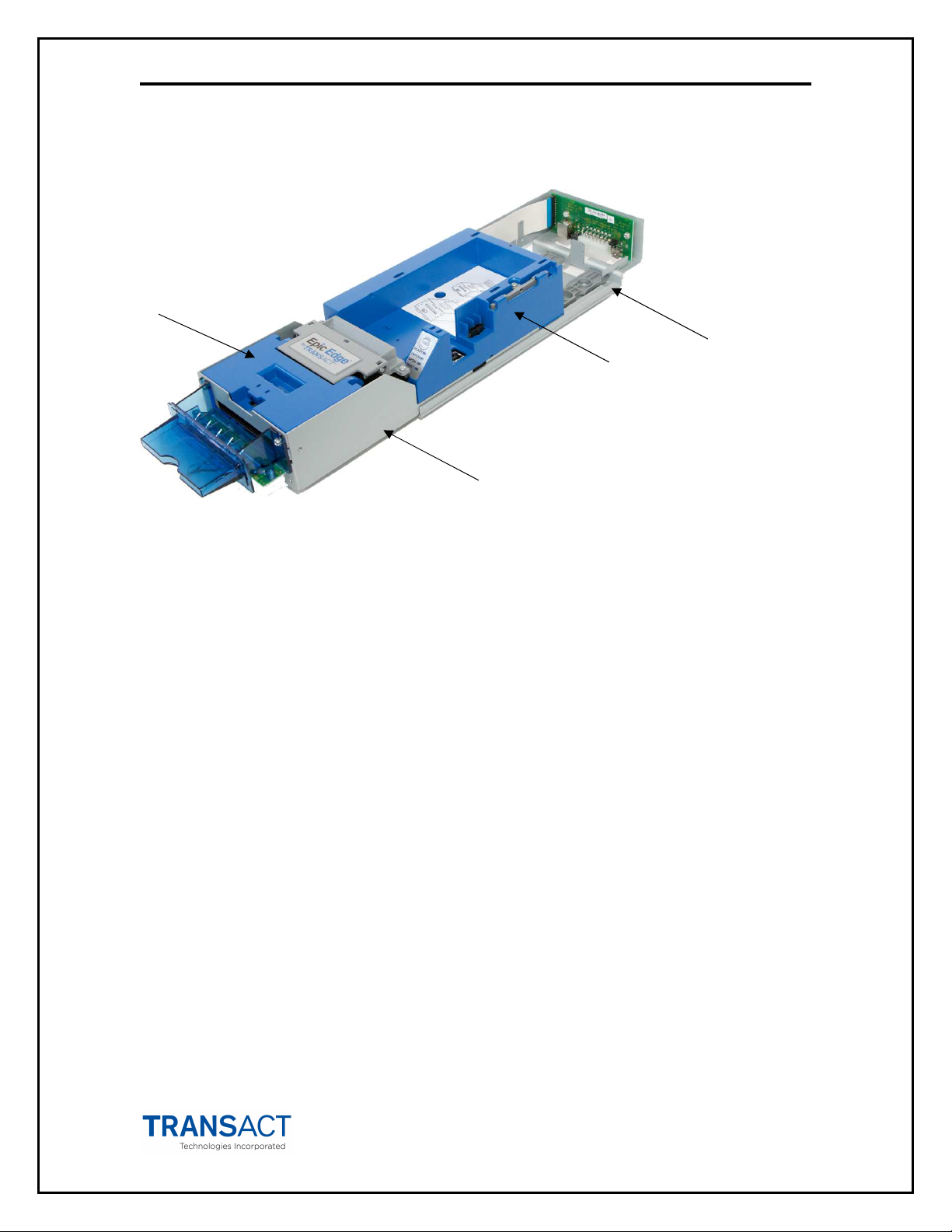
Epic Edge™ Specifications and Requirements
1
4
3
2
Figure 1. Epic Edge™ Printer Major Component Overview
1. Printer Mechanism
2. Inner Chassis Assembly
3. Printer Ticket Bucket Assembly
4. Outer Chassis Assembly
Standard Features
The following features are common to the Epic Edge™ Printers:
Key features:
• 300 DPI print resolution
• Support for 65mm x 120mm and 65mm x 156 mm tickets.
• Perforated fan folded tickets in stacks of 200, 600 or 800 tickets.
• Dedicated ServerPort connection
• Support for multiple bar code types.
• TicketBurst
completely printed and burst before transport to operator.
• HotSwap QDT
mechanism design for easy service.
• Universal interface PCB.
Other standard features:
• Selections of 7.5, 10, 12, 16.5 and 20 characters per inch printing.
• Selectable printing of Normal, Double-high, Double-wide and Double-
high/Double-wide.
• Support for stroke based character fonts
TM
– incorporating print, burst and transport zones, where the ticket is
TM
(Quick Disconnect Technology), a hot swappable printer
100-14444 Rev B August 2018 Page 11
Page 22

2- Specifications and Requirements Epic Edge OEM Integration Manual
• Sensors for Burst Ticket, Ticket Low, Top-of-Form/Ticket Out, Chassis Open,
and Ticket Taken.
• Cover Open switch.
• Modular printer mechanism, ticket tray and sliding unit for easy maintenance.
• Open ticket path for ticket jam clearing.
• Operator interface: FEED button, status LED’s (Ready/Paper/Open/Fault).
• Bezel lamp connection.
• USB imPort
TM
firmware and graphics download port.
• Print face down.
• Page mode printing.
• Audible Buzzer.
Optional Features
• 800 count ticket capacity using optional extender walls.
• Bezels (Internal and external).
Page 12 August 2018 100-14444 Rev B
Page 23
2- Specifications and Requirements Epic Edge OEM Integration Manual
(Dimensions reflect use of 200 unit ticket bucket unless otherwise noted)
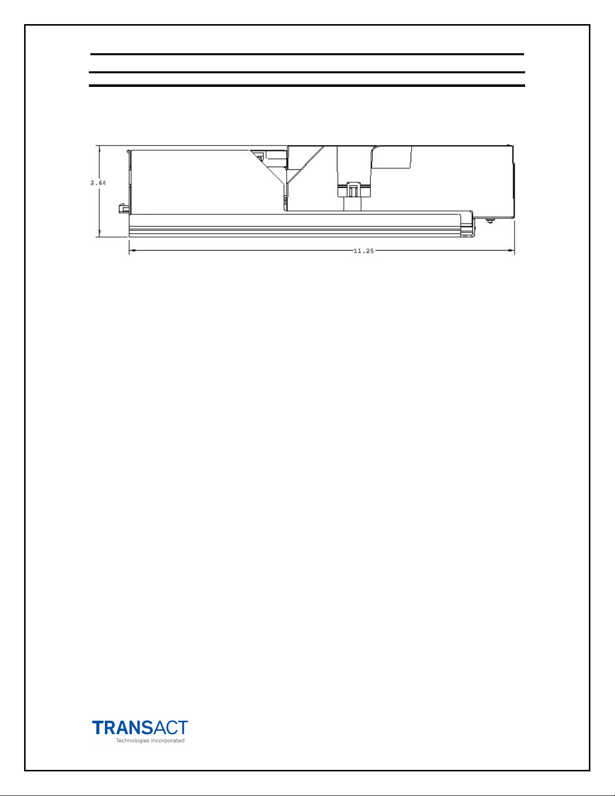
Dimensions
Figure 2. Epic Edge™ Printer: Dimensions
Size: H: 2.66" (67.6mm) W: 4.46" (113.3 mm) D: 11.25" (285.8 mm)
The Epic Edge™ is supports three interchangeable ticket capacities using extender walls. Please
be sure to specify the desired capacity when making your selections.
200 ticket setup: H: 2.66" (66.6mm) W: 4.46" (113.3 mm) D: 11.25" (285.8 mm)
600 ticket setup: H: 4.04" (102.6 mm) W: 4.46" (113.3 mm) D: 11.25" (285.8 mm)
800 ticket setup: H:
Weight: 3.8 lbs.
5.54" (140.7 mm)
W: 4.46" (113.3 mm) D: 11.25" (285.8 mm)
Interfaces
Type Bi-Directional, serial RS-232 using transmit, receive, and ground.
Protocol Ready/Busy or XON/XOFF, 9600 baud, 8 data bits, no parity,
1 start bit, 1 stop bit.
Type USB 2.0 High Speed
Protocols USB Printer, USB CDC, GSA GDS
Printer
Printer Type: Fixed linear 300 dpi thermal head.
Printer Environmental Conditions
Operating Temperature Range: 5º ~ 60ºC (41º ~ 140ºF)
Shipping/Storage Temperature Range: –10º ~ 50ºC (14º ~ 122ºF)
Operating Humidity Range: 10% ~ 90% Noncondensing only
Shipping/Storage Humidity Range: 5% ~ 90% Noncondensing only
100-14444 Rev B August 2018 Page 13
Page 24

2- Specifications and Requirements Epic Edge OEM Integration Manual
Power Requirements
24 Vdc ± 10%.
2.5 Amps max. @ 24 Vdc @ 25% print ratio.
Test Standards
BS EN 61000-6-3:2007+A1:2011
61000-6-2
ANSI C63.4-2014 or 2009
FCC Part 15 Subpart B – CLASS A
Canada ICES-003 issue 6 – CLASS A
EN55022:201+AC:2011 – CLASS A
EN 61000-3-2:2014
EN 61000-3-3:2013 – Clause 5
EN55024 :2010
IEC 61000-4-2:2008 – Level 3 Class A
IEC 61000-4-3:2006+A1:2007+A2:2010
– Level 2 Class A
IEC 61000-4-4:2012 – Level 2 Class A
IEC 61000-4-5:2014 – Level 2 Class A
IEC 61000-4-6:2013 – Level 2 Class A
IEC 61000-4-8:2009 - Level 1 Class A
IEC 61000-4-11:2004
Acoustic Noise:
Less than 65 decibels max. while printing a 30/30 format. (measured in 10 positions @ operator
level with distance of 1 meter, per ISO 779).
Mechanism Characteristics
Drawer Slide Force: TBD lbs. max.
Opening Distance: 190mm (7.5") (approximate ).
Drawer Holding Force: 4.5 lbs. (out of detents).
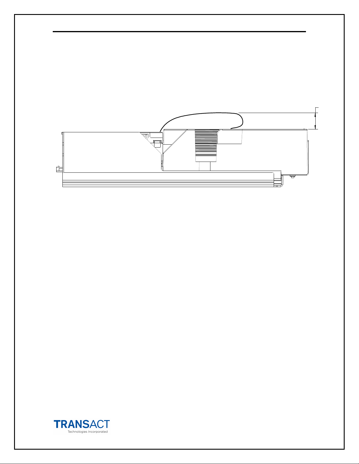
Mechanism Operating Angle: Horizontal to 45º inclination (ticket exit slot up).
Page 14 August 2018 100-14444 Rev B
Page 25
2- Specifications and Requirements Epic Edge OEM Integration Manual
45
Figure 3. Maximum Mechanism Operating Angle
100-14444 Rev B August 2018 Page 15
Page 26

2- Specifications and Requirements Epic Edge OEM Integration Manual
Printing Specifications
Print Method: Thermal Sensitive Line Dot System.
Ticket Handling: TicketBurstTM ticket buffering with burst.
Print Speed: 125 mm/sec. (5" per sec.) max.
Presentation Speed: 125 mm/sec. (8" per sec.) min.
Resolution: 300dpi x 300dpi.
Dot Pitch-Horizontal: 0.085 mm (11.4 dots/mm).
Dot Pitch-Vertical: 0.085 mm (11.4 dots/mm).
Line Feed Pitch: 3.2 mm (.125").
No. of Elements: 712 dots in-line.
Print Width: 62.5 mm (2.46").
Ticket Specifications
Ticket Width: 65 ± 1mm (2.56" ± .03").
Ticket Lengths: 156 ± 1mm (6.14" ± .04")
or
120 ± 1mm (4.72 ± .04” with short ticket adapter.
Ticket Thickness: 4.5-5.0 mils (.114-.127 mm).
Ticket Weight: 27# (102 g/m) Avg.
Brightness
Printing Colors: Black (visible light absorption: 600 ~ 700 nm)
Quantities Available: Fan-folded stacks of 200, 400, 800 tickets.
Contract Transact for complete ticket specifications and approved suppliers
:
89% Ave. (84%Min.), Test method TAPPI T-525
Bar Code Specifications
Standard Bar Code: Interleaved. 2 of 5*
Minimum Bar Width: 0.5 mm min./0.6 max.
W : N Ratio: 3 : 1 (recommended, with 12:4 wide bar width (dots):narrow bar
width (dots)).
# of Characters: 6 min./18 max.
Symbol Contrast Value: 70% min.
Applicable Standards: ANSI X3.182
gsa-p0038.001.01
*Contact Transact for information on additional supported bar codes
Page 16 August 2018 100-14444 Rev B
Page 27
2- Specifications and Requirements Epic Edge OEM Integration Manual
Design Envelope: Ticket Clearance
A minimum paper clearance distance of .75" is required above the printer’s ticket
buckets. The minimum clearance for all ticket buckets will vary, but should fall within the
.75" minimum clearance measurement.
.75
Figure 4. Design Envelope: Ticket Clearance
100-14444 Rev B August 2018 Page 17
Page 28
2- Specifications and Requirements Epic Edge OEM Integration Manual
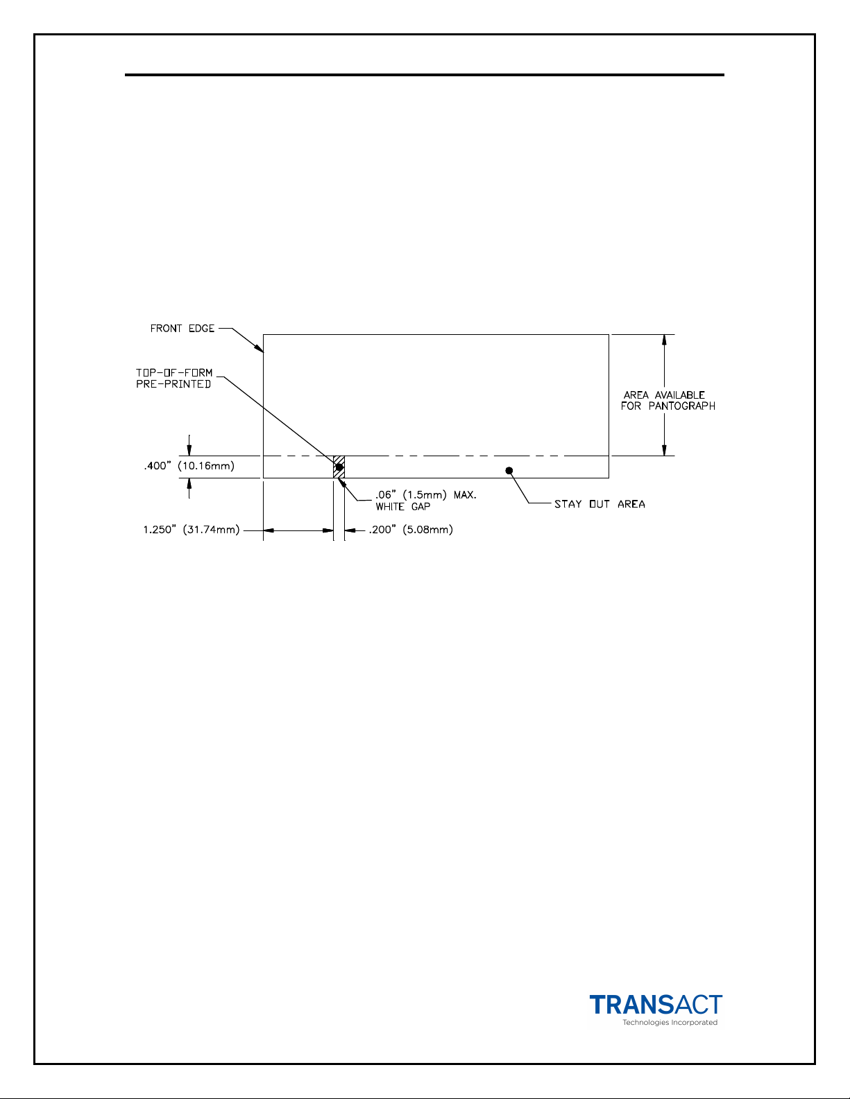
Black Dot Position and Presentation Scheme
All graphics preprinted on the ticket must be in thermal paper compatible ink.
Black Dot Position
The back of the ticket is used for the Black Dot/Top of Form indicator. For the printer to
sense when a ticket has been indexed to the printing position, a Black Dot/Top of Form
sensor is needed. It must be printed in black, thermal paper compatible, infrared
readable ink. The 10.16mm area in line with the Black Dot/Top of Form indicator and
the ticket edge (keep-out zone) must remain clear, as the Ticket Out Sensor will read
that area while the ticket is printed and presented. The remaining area on the back of the
ticket may be used for rules and disclaimer.
Figure 5. Location of Black Dot/Top of Form Indicator on Back of Ticket
Page 18 August 2018 100-14444 Rev B
Page 29
2- Specifications and Requirements Epic Edge OEM Integration Manual
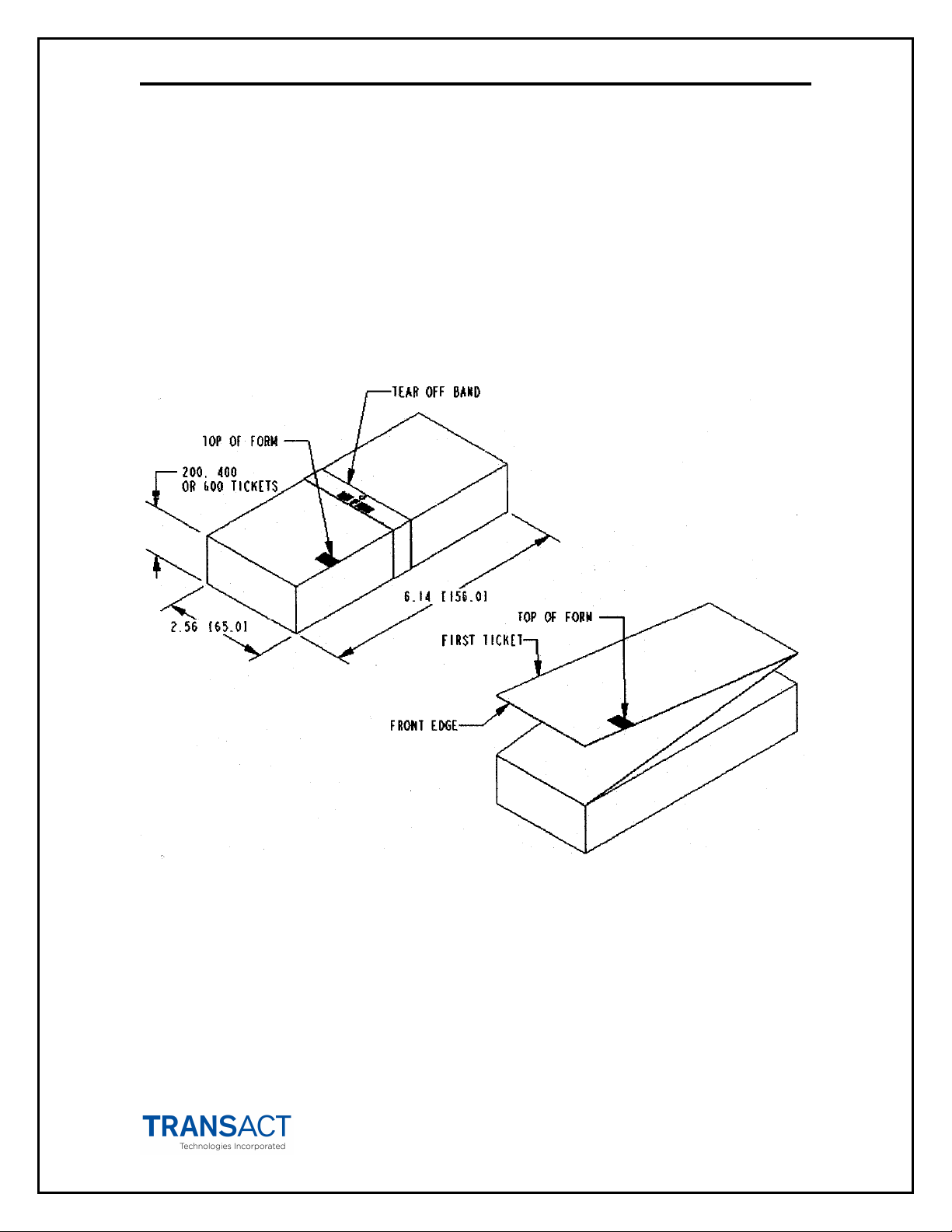
Ticket Stack Orientation
To ensure the ticket is loaded correctly into the printer, the ticket stack must be properly
loaded in the ticket box. The stack must be oriented so that the Black Dot/Top of Form
mark of the tickets is on the leading edge of the ticket, not near the perforation of the
next ticket. If the top ticket on the stack has the back facing upward, the perforation
attaching the next ticket will be toward the front of the Ticket Tray with the Black Dot/Top
of Form indicator in the rear right corner. If the print area is facing upward, the
perforation attaching the next ticket will be toward the rear of the Ticket Tray. For
instructions on inserting the first ticket into the printer, see the section “Loading Tickets
into Feeding Mechanism”.
Figure 6. Ticket Stack Orientation
100-14444 Rev B August 2018 Page 19
Page 30

Page 31

chapter
3
Mounting Requirements
100-14444 Rev B August 2018 Page 21
Page 32

This page intentionally left blank
Page 22 August 2018 100-14444 Rev B
Page 33

3-Mounting Requirements Epic Edge™ OEM Integration Manual
Mounting Requirements
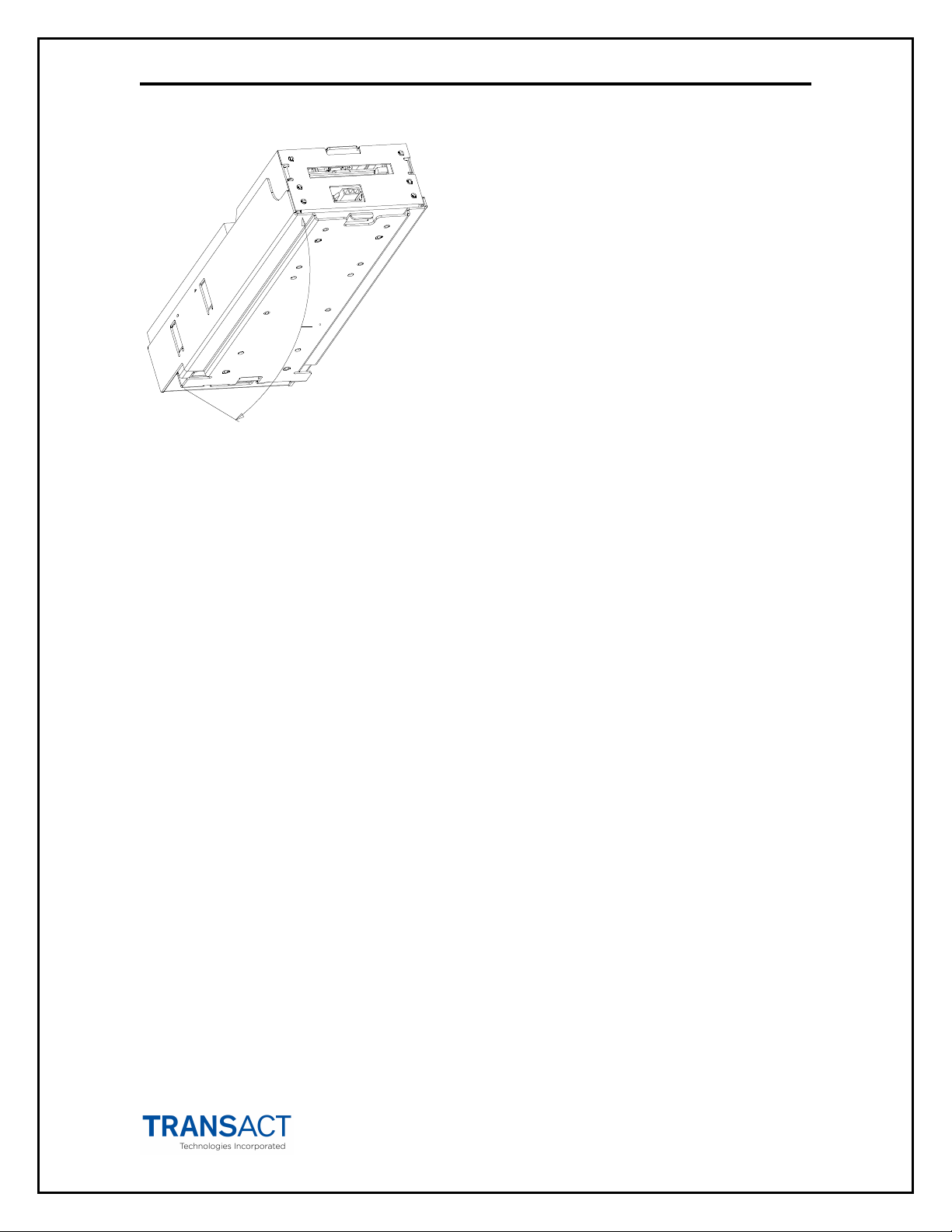
Outer Chassis to Final Product
Bottom: 4x M4x 0.7 press nuts.
4x Ф.180" thru holes.
2.024
1.904
M4x0.7
PEM NUTS
4PLS
.180
4PLS
4.430
Figure 7. Outer Chassis to Final Product
4.500
7.875
3.500
1.250
100-14444 Rev B August 2018 Page 23
Page 34

3-Mounting Requirements Epic Edge™ OEM Integration Manual
Bezel Specifications and Recommendations
Bezel to Printer Mechanism mounting points
Epic Edge™ printers are designed to accommodate a TransAct or customer-supplied
bezel assembly that is mounted following the hardware and mounting dimensions as
listed. The following drawing shows the positioning and dimensions of the Epic Edge™
printer’s mounting points.
Several bezel configurations and colors are available for the Epic Edge printer. Contact
Transact sales to determine which bezel is appropriate for your application
Front: 6x M3x 0.5 press nuts and interface with bezel.
TOP OF SLIDING MODULE
SIDE OF SLIDING MODULE
4.430
3.662
.337
.258
.940
1.831
C OF TICKET
L
Figure 8. Bezel Mounting and Hardware Requirements
2.409
.499
.500
.497
2.176
M3x0.5
PRESS NUTS
6PLS
Page 24 August 2018 100-14444 Rev B
Page 35

3-Mounting Requirements Epic Edge™ OEM Integration Manual
Figure 9. Epic Edge™ Shown with Optional Internal Bezel Assembly.
100-14444 Rev B August 2018 Page 25
Page 36

Page 37

chapter
4
Epic Edge™ Printer Sensors
100-14444 Rev B August 2018 Page 27
Page 38

This page intentionally left blank
Page 28 August 2018 100-14444 Rev B
Page 39

4-Epic Edge™ Printer Sensors Epic Edge OEM Integration Manual
Printer Sensors
The Epic Edge™ printer uses several sensors to provide feedback to the host system.
Top of Form/
Ticket Out Sensor
Cover open
Switch
Ticket Taken
Sensor
Ticket Low
Sensor
Ticket Burst
Sensor
(Covers not shown for clarity)
Figure 10. Sensor Breakdown and Locations
Cover Open Switch
The Cover Open switch detects the case where the Ticket Cover is open, and halts the
printing and ticket feeding process until the Ticket Cover is closed.
Ticket Low Sensor
A Ticket Low Sensor optically senses the number of tickets remaining in the printer’s
ticket bucket. The sensor will detect when there are 1-2 tickets remaining in the paper
bucket tickets. The ticket low status will be reported on the status byte when the host
issues a status request.
100-14444 Rev B August 2018 Page 29
Page 40

4-Epic Edge™ Printer Sensors Epic Edge OEM Integration Manual
Ticket Burst Sensor
A Ticket Burst sensor is used to detect that the ticket has been separated before it is
presented. Note that the Epic Edge™ printer incorporates a TicketBurstTM feature which
automatically burst tickets prior to presentation to the operator.
Top-of-Form/Ticket Out Sensor
A Top of Form/Ticket Out Sensor is used to control ticket loading and printing.
Ticket Taken Sensor
A Ticket Taken Sensor is used to determine when customers have actually taken the
printed ticket.
Chassis Open Sensor/Audible Alarm
The printer has a Chassis Open sensor to determine if the Inner Chassis is in the fullracked position. If the Inner Chassis is not in the fully racked position, then the printer
status LED will blink, indicating the printer is not ready.
1. Chassis Open Sensor (Sliding Module).
2. Audible Alarm Buzzer (PIEZO - game controlled).
Drawer
Open/Close
Audible Alarm
Buzzer
(Ticket Bucket not shown for clarity)
Figure 11. Open/Close Sensor/Audible Alarm
Sensor
Page 30 August 2018 100-14444 Rev B
Page 41

4-Epic Edge™ Printer Sensors Epic Edge OEM Integration Manual
Condition
Ready
LED
Paper
LED
Open
LED
Fault
LED
Cover Open
On
Off On Off
Ticket Out
On On
Off Off
Temperature Error
Blink
Off Off Blink
Paper Jam
On
Off Off Blink
Checksum Error
4-
Blink
Off Off On
Printer Status LED
The printer has been outfitted with a LED panel system that provides the condition of the
printer by using solid or blinking status LEDs to communicate status information. The
following table lists the different LED states for specific conditions within the printer.
Unit Ready On Off Off Off
Chassis Open On Off Blink Off
Ticket Low On Blink Off Off
Ram Error 2-Blink Off Off On
Table 2 Printer Status LED Indication Descriptions
100-14444 Rev B August 2018 Page 31
Page 42

Page 43

chapter
5
Electrical Connections
100-14444 Rev B August 2018 Page 33
Page 44

This page intentionally left blank
Page 34 August 2018 100-14444 Rev B
Page 45

5-Electrical Connections Epic Edge OEM Integration Manual
Interface Connections
The Epic Edge™ printer supports the following communications interfaces through the
universal interface board located at the rear of the printer. .
1. RS232 Serial
2. USB
3. NETPLEX
Communications interface Option 3 – NETPLEX utilizes communications protocols that
are proprietary to specific manufacturers and are subject to licensing requirements. In
this case only the interface pin connections are described in this manual.
Figure 12. Interface PCB Location
100-14444 Rev B August 2018 Page 35
Page 46

5-Electrical Connections Epic Edge OEM Integration Manual
Serial Communication Pin
-
Outs
RS232 Serial/NETPLEX Interface Connections
The RS232 Serial/NETPLEX interface connector is a 14 position Molex Minifit Jr®., part
number 39-30-1140, which mates with Molex part number 39-01-2140 or equivalent.
1 2 3 4 5 6 7
8 9 10 11 12 13 14
PIN # FUNCTION I/O
1 MRESET (Active low) I
2 NETPLEX TXD O
3 +12 VDC I
4 NETPLEX RXD I
5 GND 6 +24VDC 7 GND 8 +24VDC 9 Bezel Lamp – Switched +24VDC O
10 NETPLEX GND 11 RS232 RXD I
12 RS232 TXD O
13 DTR O
14 RTS O
Table 1. Serial Communication PCB Pin-Outs
*NOTE: The definition of pin 10 (NEPTPLEX GND) differs from the Epic 950 RS232
interface (FRAME GND). Connecting Frame ground to pin 10 of the Edge printer
will have no adverse effects.
Default Communication Settings
The RS-232C interface default configuration settings are:
Baud Rate: 9600 BPS
Data Bits: 8 Bits
Parity: None
Stop Bits: 1
Handshaking: None
Receive Error: Prints
Input Buffer 8,192 bytes
These communications settings may be altered only through the use of the Transact
configuration utility . Contact TransAct Technical Support for further information on this
tool.
Page 36 August 2018 100-14444 Rev B
Page 47

5-Electrical Connections Epic Edge OEM Integration Manual
USB Comm
uni
cations
PCB Pin
-
Outs
USB Connector
USB Interface Connections
Type B USB connector
Pin # FUNCTION I/O
1 VBUS 2 D- I/O
3 D+ I/O
4 GND -
Table 2. USB Interface Pin Connections
100-14444 Rev B August 2018 Page 37
Page 48

5-Electrical Connections Epic Edge OEM Integration Manual
Power Connections
Power Connector
Power Connections
Printer power may be supplied over the 14 pin RS232 connector described above or
connected through a dedicated 4 position connector on the interface boards.
Connector - 4 position Molex Minifit Jr®., part number 39-30-1040, which mates
with Molex part number 39-01-2040 or equivalent.
Pin # FUNCTION
1 +24VDC 2 GND 3 GND 4 FGND -
Table 3. Power Connections
Page 38 August 2018 100-14444 Rev B
Page 49

5-Electrical Connections Epic Edge OEM Integration Manual
ServerPort Connection
The Epic Edge™ printer includes a dedicated connection for use with the Transact
ServerPorte™ module. Harnessing guides are included in the paper bucket to improve
cable retention.
Figure 13 - ServerPort Connection
100-14444 Rev B August 2018 Page 39
Page 50

5-Electrical Connections Epic Edge OEM Integration Manual
Bezel Lamp Connector
The bezel connector is a Molex Minifit Jr®, part number 39-01-4032 and will mate with a
Molex part number 39-01-4030 or equivalent.
1
23
Figure 11. Bezel Lamp Connector Location and Connector Information
Bezel Lamp Connector Pin-Outs
PIN # FUNCTION
1 Modulated +24VDC
2 Not Connected
3 GND
Table 3. Bezel Power Connector Pin-Outs
Page 40 August 2018 100-14444 Rev B
Page 51

5-Electrical Connections Epic Edge OEM Integration Manual
USB Maintenance
Port
Micro SD card
Firmware Maintenance Ports
The Epic Edge™ printer provides two methods for updating printer firmware.
Method 1 – USB Connection to the dedicated maintenance port
Method 2 – Micro SD Card
The firmware update procedure for each of these methods is described in Chapter 6
Printer Operation.
Note: The USB cable and micro SD card MUST NOT be present to enable EGM
communications.
Figure 14. Firmware Update Ports.
100-14444 Rev B August 2018 Page 41
Page 52

Page 53

chapter
6
Printer Operation
100-14444 Rev B August 2018 Page 43
Page 54

This page intentionally left blank
Page 44 August 2018 100-14444 Rev B
Page 55

6-Printer Operation Epic Edge™ OEM Integration Manual
Racking/Unracking the Inner Chassis
All Epic Edge™ printers use a slider/detent/latch system with latch arms to retain the
Inner Chassis from accidentally being separated from the Outer Chassis. The Epic
Edge™ is opened for service by simply pulling on the ticket cover, pulling the Inner
Chassis forward from the Outer Chassis as you would a filing cabinet. If accessible, a
front-mounted release lever can also be pulled on to disengage and slide the Inner
Chassis.
\
Ticket
Cover
Outer
Chassis
Side Walls
A&B
Inner
Release
Lever
Figure 15. Racking/Unracking the Inner Chassis
Chassis
To remove the Inner Chassis, perform the following steps:
• Pull on the Ticket Cover to release the rear detents, pulling the Inner Chassis
towards you until its latches catch the forward detent slots in the Outer Chassis
Slides.
• Pull on the Release Lever and pull forward on the Inner Chassis to disconnect
from the Outer Chassis. (This assembly incorporates a HotSwap QDT (Quick
Disconnect Technology) design, which may be removed while power is still on to
the unit.)
To return the Inner Chassis to its base, perform the following steps:
• Align the base of the Inner Chassis with the outer walls of the Outer Chassis,
seating it within side walls A and B as shown in Figure 15
• While pulling outwards on the Release Lever, slide the Inner Chassis towards the
rear of the Outer Chassis until it latches at the rear of the Outer Chassis.
100-14444 Rev B August 2018 Page 45
Page 56

6-Printer Operation Epic Edge™ OEM Integration Manual
Although the Epic Edge printer incorporates Transact’s Quick Disconnect
Technology, the inner chassis is not interchangeable with Epic 950 products. Color
coded rails in the outer chassis can be used to determine compatibility
Epic Edge – Gray
Epic 950 – Black
Page 46 August 2018 100-14444 Rev B
Page 57

6-Printer Operation Epic Edge™ OEM Integration Manual
Installing the 120mm Ticket Adapter
The Epic Edge™ printer can be configured to use 65mm x 120mm ticket stock by
installing the short ticket adapter. This adapter is provided with the printer and stored in
a pocket in the paper bucket. To install the adapter remove the screw holding the
adapter in the storage slot, remove the adapter, and position it as shown in the picture
below. Install the screw to retain the adapter.
Note: The EGM application software must be configured for the 120mm ticket length for
the printer to operate correctly
Remove screw
and adapter
Install screw and
adapter
100-14444 Rev B August 2018 Page 47
Page 58

6-Printer Operation Epic Edge™ OEM Integration Manual
Loading Tickets into Feeding Mechanism
When loading new ticket stacks, be sure that there is power to the printer. The first ticket
of the stack must be inserted into the printer by hand. The Epic Edge™ printers’ ticket
tray is integrated with a guide to direct the ticket into the printer mechanism. Once the
leading ticket enters the Top of Form sensor, the ticket will be automatically fed into the
Printer Mechanism.
Figure 16. Ticket Loading and Ticket Feed Mechanism
Loading tickets into the ticket supply box: (Refer to the label on printer)
• Load tickets into the ticket supply tray, making sure that the Black Dot is
positioned as shown in Figure 16.
• Orient the tickets so that the Black Dot is towards the leading edge of the ticket.
Feeding tickets into the Printer Mechanism: (Refer to the label on printer)
• Check to ensure that the tickets have been placed in the ticket tray with the
proper black dot orientation.
• Insert the leading ticket into the Printer Mechanism’s insertion guide area. The
ticket should be fed about a ½" into the mechanism; the printer will automatically
detect the presence of the ticket and will automatically complete the loading
process.
• If printer has been slid out from rack, make sure that the inner chassis is returned
to the closed position. .
• The printer is ready to receive information.
Page 48 August 2018 100-14444 Rev B
Page 59

6-Printer Operation Epic Edge™ OEM Integration Manual
100-14444 Rev B August 2018 Page 49
Page 60

6-Printer Operation Epic Edge™ OEM Integration Manual
Removing Loaded Tickets
The Epic Edge™ printers have two ways to remove unused tickets from the printer
mechanism:
• The first way is to release the Ticket Cover by lifting and rotating backward, this
will relieve pressure to the platen allowing tickets to be removed from the rear.
This also will allow an opening that provides space to check the printer for ticket
jams or prepare the paper path for ticket replenishing.
• The second way is to use the feed button, which will feed out any remaining
tickets from within the printer mechanism.
Figure 17. Ticket Cover Shown Open for Ticket Removal
Unloading Tickets from the Printer by opening the Ticket Cover
1. Pull Inner Chassis away from the Outer Chassis until it stops in the open
position.
2. Lift and rotate the Ticket Cover backwards, towards the rear of the printer.
3. Remove all tickets from the ticket path and check for any debris.
4. Remove any remaining tickets from the ticket tray.
5. Rotate the Ticket Cover into its original closed and latched position.
6. Proceed with ticket loading procedure.
Page 50 August 2018 100-14444 Rev B
Page 61

6-Printer Operation Epic Edge™ OEM Integration Manual
Cleaning the Print Head
Two kinds of periodic cleaning operations will ensure continued high print quality from
your Epic Edge™ printer:
1. Paper dust removal. Use a soft brush to clean the paper dust from inside the printer
and chassis area. The paper dust should also be removed from the sensor optics.
2. Cleaning thermal print head. If streaking on the printed ticket is evident, the thermal
print head may need to be cleaned. This can be done by inserting a thermal printer
cleaning card, as shown in the instructions below:
Figure 18. Cleaning the Print Head
Detailed instructions
1. Open the cover and remove all tickets from ticket feed path.
2. Close the cover.
3. Open cleaning card pouch and remove cleaning card.
4. Insert cleaning card into feed path.
5. The cleaning card will automatically be drawn into the feed path.
6. Open the cover and then remove the cleaning card by gently pulling it back.
7. Repeat process if necessary.
8. Properly dispose of used cleaning card.
Purchasing Cleaning Cards
Cleaning cards are available through TransAct – consult Chapter 1 for contact
information by telephone or the Internet. Cards can also be purchased direct from
Enefco International Ltd. at (888) 578-0141.
Description: Part Number:
2.5" x 6" Thermal Cleaning Card (box of 25) 100-03322 (TransAct)
2.5" x 6" Thermal Cleaning Card (box of 25) GTP250PB (Enefco)
100-14444 Rev B August 2018 Page 51
Page 62

6-Printer Operation Epic Edge™ OEM Integration Manual
Printing a Self-test Ticket
The Epic Edge™ printer has the ability to print a pre-defined self-test ticket, to test the
normal printing functionality of the unit, and create a printout of the current printer
configuration. To print a self-test ticket, load tickets in the printer, and then press and
hold the feed button until printing starts.
Figure 19 shows an example of the information printed. Your printer may print more or
less information, depending on the version and revision of the printer firmware.
Figure 19. Sample self-test ticket.
Page 52 August 2018 100-14444 Rev B
Page 63

6-Printer Operation Epic Edge™ OEM Integration Manual
USB Download Port
Firmware Update
The Epic Edge™ printer supports two methods for updating the printer firmware.
Firmware may be updated either through the dedicated USB maintenance port or using
a micro SD card. The firmware update process is automatically initiated by the detection
of either a valid SD card insertion or a USB connection on the download port. The printer
also provides a recessed reset pushbutton near the SD connector to allow the printer to
be reinitialized without the removal of power. .
Reset Pushbutton
Micro SD card
USB Port Update
The process for updating the printer firmware using the USB maintenance port is similar
to the process used on the Epic 950 printer except the Epic Edge™ uses a USB
connection while the Epic 950 updates are performed using an RS232 connection. In
both cases the printer must be connected to a host running the Epic Printer Update tool.
Unlike the Epic 950 Printer, the Epic Edge will automatically recognize the presence of a
USB connection on the maintenance port and automatically switched to maintenance
mode
NOTE: EGM communication will be suspended during the firmware update process.
Both the USB cable and the SD card must be removed at the conclusion of the update to
reestablish the EGM communications.
USB Update Procedure
• Connect a USB cable from the host to the download port on the printer.
o The printer will reset and will enumerate as a virtual serial port on the host
PC.
Note: several resets may occur before the enumeration is completed
o When communications have been established, the printer LEDs will flash
sequentially in an up and down pattern to indicate the printer is in update
mode.
o While enumerated, the printer will block all game communications until
updates are completed and the download USB cable is removed.
100-14444 Rev B August 2018 Page 53
Page 64

6-Printer Operation Epic Edge™ OEM Integration Manual
• Start the Epic Printer Update tool on the host
• Select the appropriate serial port on the update tool.
• Point the update tool to the appropriate firmware file and select Download
• During the download the printer LEDs will flash in several different patterns
depending on the state of the update process.
• After the download has been completed, the printer will alternately blink the
Ready and Fault LEDs
• Remove the USB cable
• The printer will reset, initialize the downloaded firmware, and print a self test
ticket for confirmation. If the rare case that the printer does not automatically
reset on removal of the cable, the printer may be manually restarted using the
reset button.
• The printer will then reenable game communications and return to normal
operation.
• If the firmware download was not successful, the printer will remain in the
download mode after the USB cable is removed.
Micro SD Card Update
The Edge printer firmware may also be updated using a micro SD card.
Micro SD Card Update Procedure
• Copy the desired firmware file to a micro SD card and insert it into the receptacle
on the side of the printer. Note: The card must contain only the firmware file to be
loaded into the printer.
• The printer will automatically detect the card, disable game communications, and
read the firmware update file from the card
• During the update the printer LEDs will flash in several different patterns
depending on the state of the update process.
• After the download has been completed, the printer will alternately blink the
Ready and Fault LEDs
• Remove the SD card
• The printer will reset, initialize the downloaded firmware, and print a self test
ticker for confirmation.
• The printer will then reenable game communications and return to normal
operation.
• If the firmware download was not successful, the printer will remain in the
download mode after the SD card is removed.
.
Page 54 August 2018 100-14444 Rev B
Page 65

6-Printer Operation Epic Edge™ OEM Integration Manual
DIP Switch Settings
Some of the dip switch operations are user specific and defined in the POR.INI file.
Information on the POR.ININ file can be found in the Epic Edge Maintenance Mode
Manual. Stand switch settings are described below
Switch 1
Outside Edge of printer
Active Switch 8 Disabled
Switch 1 is the furthest to the back. The Active position is toward the outside edge of the
printer.
Switch 1 Selects configures the USB interface as either a USB Printer Class or USB
Communication Device Class. The default position is disabled which selects the USB
Printer.
Switch 2
Switch 2 configures Ticket Low. The Disabled position prevents ticket low from being
detected.
Switch 3
Switch 3 functionality is configurable in the POR.INI file.
Switch 4
Switch 4 functionality is configurable in the POR.INI file.
Switch 5
Switch 5 functionality is configurable in the POR.INI file.
Switch 6
Switch 6 is reserved
Switch 7
Switch 7 enables periodic status mode. The default position is inactive
Switch 8
Switch 8 Places the printer in Maintenance Mode when active. Refer to the Epic Edge
Maintenance Mode manual for a description of the features available in the mode. The
default setting for this switch is disabled.
100-14444 Rev B August 2018 Page 55
Page 66

7
chapter
Programming-General Information
Page 56 August 2018 100-14444 Rev B
Page 67

This page intentionally left blank
100-14444 Rev B August 2018 Page 57
Page 68

7-Programming-General Information Epic Edge™ OEM Integration Manual
Programming the Epic Edge™
NOTE: This programming guide applies to printer firmware implementing standard
Transact RS232 and USB interfaces. Some printers are configured with firmware that
implement proprietary interfaces and protocols and are beyond the scope of this
document.
The Epic Edge™ printer support multiple methods for TITO ticket generation
Low Level Printer Control Commands
Transact Template Language (TTL)
Legacy Macro Commands
Note: macro command support is provided for compatibility with legacy Epic 950
applications. It is not recommended for new implementations and is not documented in
this manual.
Compatibility Mode.
In order to maintain compatibility with existing applications, the Epic Edge™
automatically adjusts most legacy print data for proper printing with the 300 dpi print
head. Certain operations cannot be adjusted such as bitmap graphics printing. Functions
that cannot be adjusted are noted in their descriptions. The Edge printer defaults to
compatibility mode at power up.
The Epic Edge™ may also be placed in high resolution mode where all commands use
the native 300 dpi x 300 dpi print resolution.
General Programming Information
The first step in programming the Epic Edge™ is to understand how the printer works.
This section covers all the points that need to be understood to program the Epic
Edge™ Printer correctly, including both basic and advanced topics. Since the TTL
contains predefined low level command strings the general information below applies to
all printing methods.
As an ASCII-based printer, the Epic Edge™ accepts 8-bit ASCII characters as both data
and commands. The ASCII table in the Character Codes section shows the relationship
between the 8-bit values and the characters they represent. Most environments either
use the ASCII character table as the default for character values or support an ASCII
mode where characters are interpreted by the ASCII values.
The following subsections discuss general information that is needed for programming
the Epic Edge™ Printer.
Page 58 August 2018 100-14444 Rev B
Page 69

Resetting the Printer
Each print job should begin with a printer reset command. This ensures that the printer
always begins in a known state.
The command characters used to reset the Epic Edge™ are ESC (decimal value 27)
and * (decimal value 42).
Command Parameters
When sending a command, all of the command characters and parameters that make up
a command must be sent. This is especially important when using the bar code and
graphics commands. Sending too few characters to fill the required parameters for a
command will either cause the command to fail or result in subsequent data being lost.
Character Evaluation
Most of the parameters that are sent to the Epic Edge™ Printer are evaluated based on
their decimal value.
Some commands accept parameters by either their decimal value or the representative
character. For example, the set print orientation command (GS V) interprets both a
NULL (ASCII decimal value of 0) and the ‘0’ character as meaning the same thing.
16-bit Character Parameters
The maximum value a single 8-bit character can represent is 255. Some commands,
though, can take values that are greater than 255. The set horizontal starting position
command (ESC X), for example, specifies a distance (in dots) that the next text object
will print from the left margin. Because a dot is only 1/11.4 of a millimeter, a value of 255
would place the object only a little over 22 mm from the left margin. To allow for longer
distances to be specified, two 8-bit characters are used to specify the value, by
combining them into one 16-bit character. Though the calculations are all done within the
Epic Edge™ Printer, it is important to understand how the characters are handled.
For two specified 8-bit parameter values n1 and n2, the resulting 16-bit value is
computed as follows:
Value = (n1 * 256) + n2
In other words, the decimal value of the first character that is sent (n1) is multiplied by
256, and then the decimal value of the second character sent (n2) is then added to this.
To send a value under 256 to a command that takes the n1 and n2 parameters, simply
send the first character with a 0 value. For values greater than 255 but less than 512, the
100-14444 Rev B August 2018 Page 59
Page 70

Inches
Dots
n1 n2
0.5 150 0 150
1.5 450 1 194
2.0 600 2 88
2.5 750 2 238
3.0 900 3 132
4.0 1200
4
176
Font
Height
Width
Horizontal cpi
Vertical cpi
ESC P
24 12
16.9
8.4
ESC U
32 20
10.2
6.4
7-Programming-General Information Epic Edge™ OEM Integration Manual
first parameter should be sent with a value of 1. For values greater than 511 but less
than 768, the first parameter should be set to 2, and so on.
Conversions
The table below lists some common values and their relationship for converting from
dots to inches using the n1 n2 parameters.
1.0 300 1 44
3.5 1050 4 26
Table 9. Conversion from Dots to Inches
Font Statistics
The information below lists the statistics for the five internal fonts the Epic Edge™
Printer supports. Height and width are expressed in terms of dots.
ESC S 24 10 20.0 8.4
ESC M 32 16 12.7 6.4
ESC T 56 28 7.3 3.6
Table 10. Font Statistics
Objects
Objects are the basic units that the Epic Edge™ prints. An object can be either a line of
text characters, a bar code, a landscape graphic, a landscape line, or a bitmap dot line.
Each of these objects has different rules relating to them, as discussed below.
Objects can also be either active or complete. An active object is one that is still
receiving the data that composes it. A completed object is one that has been terminated.
A line of text that has not yet received a line feed or carriage return is an example of an
active object. Until a terminator character, like a line feed, is sent, more text characters
can be added to the text object. Bar code and graphic objects do not require special
terminator characters (such as line feeds). Instead, they are considered complete as
soon as they receive the correct amount of data.
Page 60 August 2018 100-14444 Rev B
Page 71

Print Modes
The Epic Edge™ supports three modes of printing: bitmap graphics mode, portrait
printing mode, and landscape printing mode. Each mode operates under very different
rules. These rules are detailed below.
Note: The Epic Edge™ Printer may be in only one print mode at a time. Multiple areas
may be printed in different print modes on a single ticket, but these areas may only be
adjacent to one another, they may not overlap.
Bitmap Graphics Mode
At its most basic level, the Epic Edge™ Printer is a direct thermal printer that creates
images on a ticket by heating the individual elements of its print head. The print head
has 712 elements (or dots). When it prints, some of these dots will be turned on
(heated), and the printer’s motor will advance the ticket by a step. The ticket stock that is
under a heated element will then turn black. For each motor step, a dot line is printed in
300 x 300 dpi resolution. Each dot line is a complete object and is printed by the Epic
Edge™ as soon as it is processed. Because of this, a bitmap dot line should not be sent
while a portrait object or a landscape page is being constructed.
INSERT THIS SIDE UP
INSERT THIS SIDE UP
Figure 20. Portrait and Landscape Print Modes
Portrait Printing Mode
On power-up, the Epic Edge™ Printer is set for portrait printing. In portrait printing mode,
text characters exit the printer from the top of the character to the bottom. It is also
possible to switch to this mode using the set print orientation command (GS V).
Portrait printing mode is also referred to as immediate mode printing, because each
object that is sent to the printer while the printer is in portrait printing mode is printed as
soon as the object is completed. No two objects may be printed on the same line in this
mode because the ticket is advanced as each object is completed and printed.
Certain commands are disabled or work differently while the Epic Edge™ is in portrait
printing mode. Exact details can be found under each command’s description.
100-14444 Rev B August 2018 Page 61
Page 72

7-Programming-General Information Epic Edge™ OEM Integration Manual
Landscape Printing Mode
By using the set print orientation command (GS V), the Epic Edge™ Printer can be
configured for landscape printing. In landscape printing, text characters exit the printer
from the left side of the ticket to the right. Before the Epic Edge™ Printer can be
switched to landscape printing mode, the set characters per line command (GS t) must
be sent. This command defines the width of the landscape page. A landscape page is
defined as the area allocated by the Epic Edge™ in which landscape text, graphics, bar
codes, and line objects may be printed. The height of this landscape page always equals
the width of the Epic Edge™’ print head. The width of the landscape page is calculated
when the set characters per line command (GS t) is sent. The width of the page is equal
to the number of characters per line multiplied by the width of the current font. The
default font is 2mm wide and the default number of characters per line is 80.
In landscape printing mode, completed objects are placed within a memory buffer in the
Epic Edge™ and are only printed when the landscape page is terminated. A form feed
(FF) character is usually used to terminate a landscape page. This causes the Epic
Edge™ to print the objects that have been placed on the landscape page and advance
to the next ticket. Note: After a landscape page is printed, the Epic Edge™ will remain in
landscape printing mode. If more objects are sent to the printer, a new landscape page
will be allocated with a width equal to the previous page. To change the width of a
landscape page, you must send the set characters per line command (GS t) followed by
the set print orientation command (GS V). Because the Epic Edge™ does not print
objects immediately in landscape mode, multiple objects can be placed on the same
line. The set horizontal starting position (ESC X) and set vertical starting position (ESC
Y) commands allow objects to be placed at any location within a landscape page. In the
case of objects positioned to overlap each other, the first object that is sent to the printer
will be printed in the overlapping area.
Objects that would normally print below the bottom of the landscape page can be either
wrapped to the next ticket or truncated by using the select line wrap/truncate modes
command (GS T). Unless the set vertical starting position command (ESC Y) is used,
the first object sent will be printed at the top of the landscape page.
Page 62 August 2018 100-14444 Rev B
Page 73

Text Objects
A text object is simply a line of printable characters. A text object is created whenever
the Epic Edge™ receives a printable character that is not otherwise part of a command.
Once it is created, a text object will remain active until it is terminated.
While a text object is active, any printable characters sent to the Epic Edge™ will be
added to that text object. The only exceptions are printable characters that are sent as
part of a command. While a text object is active, commands that alter text line attributes
(such as font and double-high character commands) are ignored. Commands that alter
text character attributes (such as double-wide and inverse) may be sent at any time.
Line attributes include the five basic fonts (P, M, U, and T), plus the double-high font
command (GS DC2). These commands may not be issued while a text object is active;
instead they should be issued before a text object is begun. The text line attribute
persists until another font command is received. The double-high line attribute persists
either until the cancel double-high command (GS DC3) is sent or the current font is
changed.
The character attribute commands include the set font to double wide (SO) and set
inverse print mode (GS RS) commands. These commands may be issued or canceled at
any time. Character attributes persist only until the end of a text object.
A text object can be terminated with a carriage return, a line feed, or both, in either
combination. If the length of the text object exceeds the space allowed for printing, it will
either wrap to the next line or truncate at the end of the printable area. The decision to
wrap or truncate is determined by the select line wrap/truncate mode command (GS T).
By default, text objects will wrap to the next line.
Bar Code Objects
A bar code object is created by the print bar code command (GS k). Specified within the
command is the symbology to be used, amount of data to be encoded, and data itself.
Other attributes of the bar code, such as height and width, can be set using other
commands.
The set bar code height command (GS h) specifies the height of the bar in increments of
1/8 mm. The maximum height for a bar code is 32 mm. In cases where a taller bar code
is needed, a second bar code can be printed below the first at the same left offset. The
set bar code module width (GS w) and set bar code element width (GS W) commands
can be used to alter the width of the bar code. See the command descriptions later in the
next section for a full explanation of the differences between these two commands.
The limitations of each symbology must be adhered to when sending data for a bar
code. For example, you should not send alphabetic characters to symbologies that only
accept numeric data (like the UPC/EAN symbology).
Other items must also be considered when printing bar codes:
(If any of these items are ignored, the printed bar code may be unreadable.)
100-14444 Rev B August 2018 Page 63
Page 74

7-Programming-General Information Epic Edge™ OEM Integration Manual
• Sufficient blank space on either side of the bar code must be left to create a quiet
zone.
• A good ratio/element size must be selected if the default values are not being
used.
• Adequate room must be available for the bar code to be printed on the ticket.
• Bar codes may only be printed in black, for accurate infrared scanning, using
thermal media with a visible light absorption of 600-700 nm for black printing.
A bar code object is self-terminating and will be processed as soon as the proper
amount of data has been sent to it. The print bar code command’s (GS k) second
parameter specifies whether a fixed amount of data will be sent or whether delimiters will
be used. In either case, the data sent must match the parameter setting. If a fixed
number of characters are specified, then the exact number of characters specified must
be sent. If delimiters are indicated, then matching characters must be sent before and
after the bar code data to specify the beginning and end of the data. If an incorrect
number of characters or delimiters are sent, the Epic Edge™ will not print correctly.
Bar codes that are too long to fit within the printable area of a ticket are truncated. This
usually results in an unreadable bar code being printed. To correct this condition, a
narrower ratio must be set, fewer digits encoded, or a more compact symbology used.
Supported Bar codes
Codabar
Code 3 of 9
Code 128-A
Code 128-B
Code 128-C
Code 128-Auto
EAN-8
EAN-13
Interleaved 2 of 5
UPC-A
UPC-E
Code93
Graphic Objects
Graphic objects are created by the landscape printing mode graphics command (GS *).
Graphic objects may only be printed as part of a landscape page. To print a graphic
without entering landscape printing mode, you must use bitmap graphics mode.
No landscape graphic may be wider than 256 dots, though they may be as tall as the
width of the Epic Edge™’ print head. If a graphic needs to be printed wider than 256
dots, either subdivide it into narrower sections or print it using bitmap graphics
commands.
Page 64 August 2018 100-14444 Rev B
Page 75

Line Objects
Line objects are created using the draw line in landscape printing mode command (GS
l).
Line objects may only be printed as part of a landscape page. If the length of a line
object is set to exceed the printable area of a ticket, the line will be truncated at the end
of the printable area.
General Notes
In any mode, the set feed length command (GS L) is used to determine how far the Epic
Edge™ will feed in search of a Black Dot/Top of Form indicator. If the Epic Edge™ finds
a Black Dot/Top of Form indicator before the maximum feed distance is reached, it will
stop at that point, rather than continuing. This command is only needed when dealing
with continuous-feed tickets.
100-14444 Rev B August 2018 Page 65
Page 76

chapter
8
Printer Commands
Page 66 August 2018 100-14444 Rev B
Page 77

This page intentionally left blank
100-14444 Rev B August 2018 Page 67
Page 78

8-Printer Commands Epic Edge™ OEM Integration Manual
in the description of the command.
can have values from zero to 255.
exampl
e, [ESC] 1 represents 1BH followed by 31H.
This section describes the commands for programming the Epic Edge™ Printer. Each
section contains a description of each command, listed by name in alphabetical order.
The ASCII, hexadecimal, and decimal values for each command are also provided. See
Appendix A for a list of ASCII, hexadecimal, and binary codes.
Some of the tasks that can be accomplished with these commands include the following:
• Define bar code size and position.
• Return firmware revision and printer status information.
• Define ticket orientation.
• Print graphics in inverse text mode and print enlarged characters.
• Send line feeds and carriage returns.
Appendix A also contains a list of all commands, and their functions.
Nomenclature
When describing control codes, confusion often occurs as to whether the command
description is decimal, hexadecimal, or ASCII. To minimize the problem, this
programmer’s guide uses the following nomenclature when describing control code
sequences.
[ ] Encloses a control character. [ ] represents a single, 8-bit value as
defined in the standard ASCII tables. The ASCII Code Table in
Appendix B lists the control codes. An example would be [ESC], which
would represent a 1BH or 27 decimal.
< > Encloses an 8-bit value in decimal format. The value is from zero to
255. An example is <2>, which represents 02H or 2 decimal.
<xNN> Encloses an 8-bit value in hexadecimal format. The value is from x00 to
xFF. An example is <x12>, which represents 12H or 18 decimal.
<n> Indicates a variable parameter. The variable parameter, <n>, can have
a value from zero to 255. The meaning of <n> is described and defined
<n1> <n2> Indicates that there are two parameters, <n1> and <n2>, where both
x All other characters in control strings represent ASCII characters. For
In many cases, applications require that control sequences be specified in hexadecimal
or decimal codes. In most cases, commands are specified in ASCII, hexadecimal, and
decimal. The table in Appendix A lists ASCII, hexadecimal, and decimal equivalents.
Page 68 August 2018 100-14444 Rev B
Page 79

8-Printer Commands Epic Edge™ OEM Integration Manual
Available Commands
Name Description Page
BEL Audio alert 71
HT Horizontal Tab 72
LF Line Feed 73
FF Form Feed 74
CR Carriage Return 75
SO Set Font to Double-wide 76
DC4 Cancel Double-wide Mode 77
ENQ Request Combined Printer Status 78
20h - FFh Printable Characters 79
ESC ENQ 1 Return Version Information 80
ESC BEL Configure audio alert 81
ESC SP n Set Right-Side Character Spacing 82
ESC ! n Select print mode(s) 83
ESC $ n1 n2 Set Absolute Horizontal Position in page mode 84
ESC * Reset to Defaults 85
ESC @ Reset to Power-up Condition 86
ESC B Print Bitmap (BMP) Image 87
ESC E Form Feed 88
ESC F Select Fonts 89
ESC G n Turn Double-strike mode on/off 90
ESC J n Feed n Sublines 91
ESC M Set Font to 12 cpi 92
ESC P Set Font to 16 cpi 93
ESC S Set Font to 20 cpi 94
ESC T Set Font to 7 cpi 95
ESC U Set Font to 10 cpi 96
ESC V Return Firmware Revision 97
ESC W n1 n2 Wrap Data 98
ESC X n1 n2 Set Horizontal Starting Position 99
ESC Y n1 Set Vertical Starting Position 100
ESC c n Select color Error!
Bookmark not defined.
ESC t n Set print direction in page mode 101
GS DC2 Set Font to Double-high 102
GS DC3 Cancel Double-high 103
GS RS Set Inverse Print Mode 104
GS US Cancel Inverse Print Mode 105
GS ! n Select character size 106
GS $ n1 n2 Set Absolute Vertical Position in page mode 107
GS * n1 n2 t h w d1…dm Landscape Mode Graphics 108
GS ? CRC Verification 109
GS 0 n1 n2 t name NUL Print User Defined Image 110
GS 1 Enter Download Image mode 111
GS 3 n Image Status Handler 112
GS A n1 n2 Bar Code Start Position 113
GS E Set Validation Number Field 114
GS F n1 n2 n3 n4 n5 Set Field in page mode 115
GS G n1 n2 t d Print Custom Graphic 117
GS L n1 n2 Set Feed Length 118
GS S Return Printer Status 119
GS T <n> Select Line Wrap/Truncate Modes 120
100-14444 Rev B August 2018 Page 69
Page 80

8-Printer Commands Epic Edge™ OEM Integration Manual
GS V <n> Set Print Orientation 121
GS W Thin Thick Set Bar Code Element Width 122
GS d <n> Feed n Text Lines 123
GS h <n> Set Bar Code Height 124
GS k n m d1…dk Print Bar Code 125
GS l n1 n2 l1 l2 m Draw Line in Landscape Mode 126
GS t <n> Set Characters per Line (Landscape) 127
GS u <n> Set Characters per Line (Portrait) 128
GS w <n> Set Bar Code Module Width 129
GS y Request Combined Printer Status 130
GS z Request Printer Status 131
Page 70 August 2018 100-14444 Rev B
Page 81

8-Printer Commands Epic Edge™ OEM Integration Manual
ASCII
Hexadecimal
Decimal
Parameters
BEL – Audio Alert
Description
Generates an audio alert. The default is a single sound, lasting the period of time
defined by the audio alert setting defined by the ESC BEL command. If the audio alert
is turned off by setting the number of alert cycles in ESC BEL to zero, this command
does not function.
See also:
ESC BEL <n1> <n2> <n3> – Configure Audio Alert
Expression
[BEL]
07H
<7>
None
100-14444 Rev B August 2018 Page 71
Page 82

8-Printer Commands Epic Edge™ OEM Integration Manual
ASCII
Hexadecimal
09H
Decimal
<9>
Parameters
None
HT – Horizontal Tab
Description
Moves the cursor position to the next multiple of eight single-width characters. If the HT
command causes the cursor to move beyond the printable area, the text will wrap to the
next line.
Note that double-width characters count as two single-width
characters.
Expression
[HT]
Page 72 August 2018 100-14444 Rev B
Page 83

8-Printer Commands Epic Edge™ OEM Integration Manual
ASCII
[LF]
Hexadecimal
Decimal
Parameters
LF – Line Feed
Description
Prints the current line of text, and advances the text position to the beginning of the next
line. Note that the line feed, line feed/carriage return, carriage return, and carriage
return/line feed instructions all behave as a single line feed. If the current line extends
beyond the printable area, the text will wrap to the next printable area.
The double-wide text attribute will be cleared after the line is printed.
Expression
0AH
<10>
None
100-14444 Rev B August 2018 Page 73
Page 84

8-Printer Commands Epic Edge™ OEM Integration Manual
ASCII
[FF]
Hexadecimal
0CH
Decimal
Parameters
FF – Form Feed
Description
This command prints the contents of the text buffer, and then advances the print media.
The form is advanced until either of the following two conditions occurs:
• The feed distance specified by the GS L command has been reached.
-or-
• A Black Dot/Top of Form indicator has been detected on the print media.
When the printer is initially powered on, the default feed distance
stored in NVRAM is used. This value has a factory default of 7.5
inches, and can be overridden by specifying a new value using the GS
L macro command.
Feed distances specified via GS L are cleared whenever the printer is powered down, or
by issuing the ESC @ or ESC * reset commands.
This command shares identical functionality with the escape command ESC E.
See also:
ESC E – Form Feed
Expression
<12>
None
Page 74 August 2018 100-14444 Rev B
Page 85

8-Printer Commands Epic Edge™ OEM Integration Manual
ASCII
[CR]
Hexadecimal
0DH
Decimal
<13>
Parameters
CR – Carriage Return
Description
Prints the current line of text, and advances the text position to the beginning of the next
line. Note that the line feed, line feed/carriage return, carriage return, and carriage
return/line feed instructions all behave as a single line feed. If the current line extends
beyond the printable area, the text will wrap to the next printable area. The double-wide
text attribute will be cleared after the line is printed.
Expression
None
100-14444 Rev B August 2018 Page 75
Page 86

8-Printer Commands Epic Edge™ OEM Integration Manual
ASCII
Hexadecimal
Decimal
<14>
Parameters
None
SO – Set Font to Double-wide
Description
Causes all the text that follows the command on the same line to be printed as doublewide characters. Double-wide characters are canceled by a line feed (CR or LF) or the
DC4 command.
Double-wide is a character attribute which is available on a character-by-character basis.
Double-wide text can be canceled at any point on the line, and is automatically canceled
at the end of the line. Therefore, subsequent lines will not be printed as double-wide text
unless the SO command is reissued at the beginning of each line.
See also:
DC4 – Cancel Double-wide Mode
Expression
[SO]
0EH
Page 76 August 2018 100-14444 Rev B
Page 87

8-Printer Commands Epic Edge™ OEM Integration Manual
ASCII
[DC4]
Hexadecimal
14H
Decimal
<20>
Parameters
DC4 – Cancel Double-wide Mode
Description
Cancels double-wide text printing and returns the text to normal.
See also:
SO – Set Font to Double-wide
ESC W – Wrap Data
Expression
None
100-14444 Rev B August 2018 Page 77
Page 88

8-Printer Commands Epic Edge™ OEM Integration Manual
ASCII
Hexadecimal
Decimal
<5>
Parameters
None
ENQ – Request Combined Printer Status
Description
Returns four status bytes: GS y (so that the status string can be recognized/parsed by
the host), followed by the response byte for the GS S Return Printer Status command
and then by the response byte for the GS z Request Printer Status command.
The ENQ and GS y commands are the same and produce the same result.
See also:
GS y – Request Combined Printer Status
GS S – Return Printer Status
GS z – Request Printer Status
Expression
ENQ
05
Page 78 August 2018 100-14444 Rev B
Page 89

8-Printer Commands Epic Edge™ OEM Integration Manual
ASCII
Hexadecimal
Decimal
Parameters
None
20h – FFh – Printable Characters
Description
These characters, while not part of an escape (command) sequence, will be printed
using the currently selected font. The standard, printable ASCII characters are
associated with their normal values, which range from decimal value 32 to decimal value
255.
Expression
See Appendix A for a summary of character codes.
20H-FFH
<32>-<255>
100-14444 Rev B August 2018 Page 79
Page 90

8-Printer Commands Epic Edge™ OEM Integration Manual
ASCII
Hexadecimal
1BH 05H 1
Decimal
<27> <5> 1
Parameters
None
ESC ENQ 1 – Return Version Information
Description
Returns version information for your Epic Edge™ printer, in the format:
[ENQ]1<length byte><Name/version string>
Example output:
[ENQ]1<20>TransAct M950 S00114
Expression
[ESC] ENQ 1
Page 80 August 2018 100-14444 Rev B
Page 91

8-Printer Commands Epic Edge™ OEM Integration Manual
ASCII
Hexadecimal
1BH 07H <
n1
> <n2> <n3>
Decimal
<27> <7> <
n1
> <n2> <n3>
<n3> is the off time of the alert cycle in ten Ms intervals
ESC BEL – Configure Audio Alert
Description
The ESC BEL command alters the way the audio alert sounds when the BEL command
is issued. The default is a single sound lasting the period of time defined by the audio
alert setting parameters below.
See also:
BEL – Audio Alert
Expression
[ESC] [BEL] <n1> <n2> <n3>
Parameters <n1> is the number of alert cycles
<n2> is the on time of the alert cycle in ten Ms intervals
100-14444 Rev B August 2018 Page 81
Page 92

8-Printer Commands Epic Edge™ OEM Integration Manual
ASCII
[ESC] [SP] <
n>
Hexadecimal
Decimal
Range: 0
-
255
ESC SP – Set Right-Side Character Spacing
Description
This command sets the character spacing for the right side of the character. The spacing
value <n> is specified in dots, where 1 dot = 1/203 inch.
Expression
1BH 20H <n>
<27> <32> <n>
Parameters <n> = spacing value in dots, where 1 dot = 1/203 inch
Page 82 August 2018 100-14444 Rev B
Page 93

8-Printer Commands Epic Edge™ OEM Integration Manual
ASCII
Hexadecimal
1BH 21H <
n>
Decimal
<27> <33> <
n>
spacing for 7 CPI.
ESC ! – Select Print Mode(s)
Description
Selects the font and right-side character spacing, using the convention shown below.
Expression
[ESC] ! <n>
Parameters <n> = value from 0-4 which selects one of the following options:
n = 0 selects the 10x24 font and sets the intercharacter
spacing for 20 CPI.
n = 1 selects the 12x24 font and sets the intercharacter
spacing for 16 CPI.
n = 2 selects the 16x32 font and sets the intercharacter
spacing for 14 CPI.
n = 3 selects the 20x32 font and sets the intercharacter
spacing for 12 CPI.
n = 4 selects the 28x56 font and sets the intercharacter
100-14444 Rev B August 2018 Page 83
Page 94

8-Printer Commands Epic Edge™ OEM Integration Manual
ASCII
[ESC] $ <
n1><n2>
Hexadecimal
1BH 24H <
n1><n2>
Decimal
<27> <36> <
n1><n2>
n2 = least significant byte of start position
ESC $ – Set Absolute Horizontal Position in page mode
Description
Sets the horizontal print position measured from the left edge of the page, for the
currently selected print direction. Distance is specified in dots, where 1 dot = 1/203 inch.
The n1 and n2 parameters are evaluated to form a 16-bit word as follows: first, the n1
parameter’s decimal value is multiplied by 256, then the result is added to the decimal
value of the n2 parameter.
Expression
Parameters n1 = most significant byte of start position
Page 84 August 2018 100-14444 Rev B
Page 95

8-Printer Commands Epic Edge™ OEM Integration Manual
ASCII
[ESC] *
Hexadecimal
1BH 2AH
Decimal
<27> <42>
Parameters
ESC * – Reset to Defaults
Description
Returns the printer to its power-up condition, clears all buffers, and resets all character
attributes. The ESC * command is the same as the ESC @ command.
See also
ESC @ – Reset to Power-up Condition
Expression
None
100-14444 Rev B August 2018 Page 85
Page 96

8-Printer Commands Epic Edge™ OEM Integration Manual
ASCII
[ESC] @
Hexadecimal
1BH 40H
Decimal
<27> <64>
Parameters
ESC @ – Reset to Power-up Condition
Description
Returns the printer to its power-up condition, clears all buffers, and resets all character
attributes. The ESC @ command is the same as the ESC * command.
See also
ESC * – Reset to Defaults
Expression
None
Page 86 August 2018 100-14444 Rev B
Page 97

8-Printer Commands Epic Edge™ OEM Integration Manual
ASCII
[ESC] <BMP file>
Hexadecimal
1BH <BMP file>
Decimal
<27> <BMP file>
letter B as the first byte.
ESC B – Print Bitmap (BMP) Image
Description
This command will print a bitmap (Microsoft BMP file format) image.
To use this command, send the ESC (1Bh) character followed by the complete BMP file.
Note that the first character of a bitmap file is always “B”, therefore ESC B is recognized
by the Epic Edge™ as the code to print a bitmap file.
The printer decodes the BMP file header and will print the image data after checking
important parameters, such as width, height and number of colors.
Note: Only monochrome or 4-bit color BMP file images are supported.
Other BMP file formats are ignored.
Further information about the Microsoft BMP bitmap file format is available on-line at
http://www.faqs.org/faqs/graphics/fileformats-faq. Note that this site is not affiliated with
TransAct Technologies
Expression
Parameters <BMP file> - contents of a Microsoft
bitmap (BMP) format file, with the ASCII
100-14444 Rev B August 2018 Page 87
Page 98

8-Printer Commands Epic Edge™ OEM Integration Manual
ASCII
[ESC] E
Hexadecimal
1BH 45H
Decimal
<27> <69>
Parameters
None
ESC E – Form Feed
This command prints the contents of the text buffer, and then advances the print media.
The form is advanced until either of the following two conditions occurs:
• The feed distance specified by the GS L command has been reached
-or-
• A Black Dot/Top of Form indicator has been detected on the print media
When the printer is initially powered on, the default feed distance
stored in NVRAM is used. This value has a factory default of 7.5
inches, and can be overridden by specifying a new value using the GS
L macro command.
Feed distances specified via GS L are cleared whenever the printer is powered down, or
by issuing the ESC @ or ESC * reset commands.
This command shares identical functionality with the FF command.
See also:
FF – Form Feed
Expression
Page 88 August 2018 100-14444 Rev B
Page 99

8-Printer Commands Epic Edge™ OEM Integration Manual
ASCII
[ESC] F <
n1><n2><n3>
Hexadecimal
Decimal
ESC F – Select Fonts
Description
The ESC F command selects a font based on the specified point size, width ratio and
attributes.
Expression
1BH 46H <n1><n2><n3>
<27> <70> <n1><n2><n3>
Parameters n1 = Point size of font
n2 = Font width ratio. This parameter is
currently reserved for future use, but must
have a value specified.
n3 = Attributes, where n3=1 selects
double strike, and values with the most
significant bit (MSB) set to 1 will select
fixed pitch fonts.
100-14444 Rev B August 2018 Page 89
Page 100

8-Printer Commands Epic Edge™ OEM Integration Manual
ASCII
Hexadecimal
1BH 47H <
n>
Decimal
<27> <71> <
n>
LSB = 1 turns on double
-
strike mode
ESC G – Turn Double-strike Mode On/Off
This command turns double-strike mode on or off. When the least significant bit (LSB) of
the parameter n is 0, double-strike mode is turned off. When the LSB is 1, double-strike
mode is turned on.
Expression
ESC G <n>
Parameters n = value ranging from 0 to 255, where:
LSB = 0 turns off double-strike mode
Page 90 August 2018 100-14444 Rev B
 Loading...