

Page 1
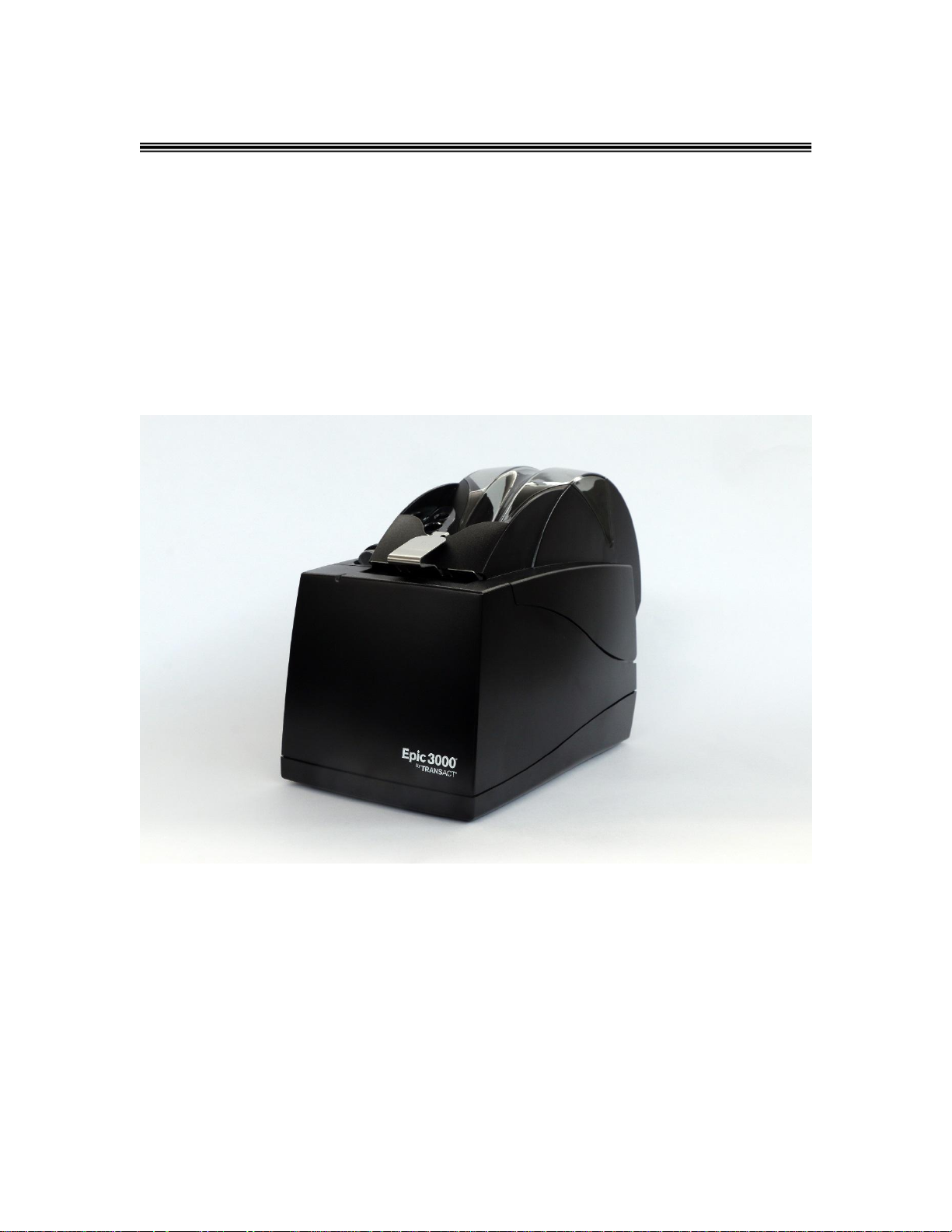
Epic 3000
Programmer’s Guide
PN 100-14362, Rev A Dec 2015
Page 2

Programming Codes Epic 3000 Programmer’s Guide
Page 2 Rev A 100-14362
Page 3

Epic 3000 Programmer’s Guide Programming Codes
Revision
Description of Change
Date
ECR
1
Initial Draft
Dec
2015
A
Initial Release
Dec
2015
ER30301
Change History
100-14362 Rev A Page 3
Page 4

Programming Codes Epic 3000 Programmer’s Guide
Federal Communications Commission Radio Frequency Interference Statement
The EPIC 3000 Printer complies with the limits for a Class A computing device in
accordance with the specifications in Part 15 of FCC rules. These regulations are
designed to minimize radio frequency interference during installation; however, there is
no guarantee that radio or television interference will not occur during any particular
installation. Interference can be determined by turning the equipment off and on while
the radio or television is on. If the printer causes interference to radio or television
reception, try to correct the interference by one or more of the following measures:
1. Reorient the radio or television receiving antenna
2. Relocate the printer with respect to the receiver
3. Plug the printer and receiver into different circuits
If necessary, the user should consult their dealer or an experienced radio/television
technician for additional suggestions. The user may find the following booklet prepared
by the Federal Communications Commission helpful: How to Identify and Resolve
Radio/TV Interference Problems. This booklet is available from the US Government
Printing Office, Washington, DC 20402. Ask for stock number 004-000-00345-4.
Canadian Department of Communications Radio
Interference Statement
The EPIC 3000 Printer does not exceed Class A limits for radio noise emissions from
digital apparatus set out in the Radio Interference Regulations of the Canadian
Department of Communications.
Regulatory Compliance
FCC Class A
ULc
CE Mark
UL 1950
TUV
Page 4 Rev A 100-14362
Page 5

Epic 3000 Programmer’s Guide Programming Codes
Disclaimer
NOTICE TO ALL PERSONS RECEIVING THIS DOCUMENT:
The information in this document is subject to change without notice. No part of this
document may be reproduced, stored or transmitted in any form or by any means,
electronic or mechanical, for any purpose, without the express written permission of
TransAct Technologies, Inc. ("TransAct"). This document is the property of and contains
information that is both confidential and proprietary to TransAct. Recipient shall not
disclose any portion of this document to any third party.
TRANSACT DOES NOT ASSUME ANY LIABILITY FOR DAMAGES INCURRED,
DIRECTLY OR INDIRECTLY, FROM ANY ERRORS, OMISSIONS OR
DISCREPANCIES IN THE INFORMATION CONTAINED IN THIS DOCUMENT.
TransAct cannot guarantee that changes in software and equipment made by other
manufacturers, and referred to in this publication, do not affect the applicability of
information in this publication.
Copyright
© 2015 TransAct Technologies, Inc. All rights reserved.
Revision Level A
Dec 2015
Printed in USA
Trademarks
Some of the product names mentioned herein are used for identification purposes only
and may be trademarks and/or registered trademarks of their respective companies.
BANKjet, 50Plus, Insta-Load, Ithaca, "Made to Order. Built to Last", Magnetec, PcOS,
POSjet, PowerPocket, iTherm", "PRINT IT. STICK IT.", POWEROLL, "RECEIPTS
THAT REGISTER", and TransAct are registered trademarks and Epic 950, Epicenteral,
Flex-Zone, imPort, ithaColor, KITCHENjet, Momentum, QDT and TicketBurst are
trademarks of TransAct Technologies, Inc.
QR Code is registered trademark of DENSO WAVE INCORPORATED in JAPAN and
other countries.
EPSON and ESC/POS are registered trademarks of Seiko Epson Corporation in Japan
and other countries.
100-14362 Rev A Page 5
Page 6

Programming Codes Epic 3000 Programmer’s Guide
Table of Contents
Change History .................................................................................. 3
Canadian Department of Communications Radio Interference
Statement .......................................................................................... 4
Regulatory Compliance ...................................................................... 4
Disclaimer ......................................................................................... 5
Copyright ......................................................................................................................... 5
Trademarks ..................................................................................................................... 5
Table of Contents ............................................................................................................ 6
Figures .......................................................................................................................... 12
Tables ........................................................................................................................... 14
About the EPIC 3000 Printer ........................................................... 15
Who Should Read This Guide? ..................................................................................... 15
What Is Included in This Guide? .................................................................................... 15
Warranty Options .......................................................................................................... 15
Technical and Sales support ......................................................................................... 16
On-line Technical Support ..................................................................................... 16
Telephone Technical Support ................................................................................ 16
Return Materials Authorization and Return Policies ............................................... 16
Service Programs .................................................................................................. 16
Sales Support ........................................................................................................ 17
Contact Information ............................................................................................... 17
EPIC 3000 Specifications and Requirements ................................................................ 18
Standard Features ........................................................................................................ 18
General Specifications .................................................................................................. 20
Printing Specifications ........................................................................................... 20
Electrical Characteristics ............................................................................................... 20
Internal AC Powered ............................................................................................. 20
Thermal Print Head ....................................................................................................... 20
Media Specifications ..................................................................................................... 21
Receipt Paper ........................................................................................................ 21
Monochrome ...................................................................................................... 21
Paper Low ......................................................................................................... 21
Paper Out .......................................................................................................... 21
Receipt Printing, Auto Cutter Position ................................................................ 21
Buzzer ........................................................................................................................... 22
Cover Interlock .............................................................................................................. 22
Communications Interface ............................................................................................. 22
USB Interface ........................................................................................................ 22
Setup ............................................................................................... 22
Verifying the Configuration ............................................................................................ 22
Connecting Communications Cables ..................................................................... 22
Verify the Firmware Configuration ......................................................................... 23
Installing Paper ............................................................................................................. 23
Indicator Light................................................................................................................ 24
Error Indication and Blink Patterns ..................................................................... 24
Power Saving Modes .................................................................................................... 25
Sleep ................................ ..................................................................................... 25
Green/Standby ...................................................................................................... 25
Page 6 Rev A 100-14362
Page 7

Epic 3000 Programmer’s Guide Programming Codes
Testing the Printer Overview ......................................................................................... 26
Using Self-Test, Configuration, and Hex Dump Mode ............................................ 26
Entering Self-Test, and Configuration mode ...................................................... 26
Testing the printer .............................................................................................. 26
TEST-Receipt ................................................................................................ 26
TEST-Head Test ............................................................................................ 26
Configuring Options ........................................................................................... 26
TEST- Configuration ...................................................................................... 27
Factory Test ................................ ....................................................................... 27
Level 0 Diagnostics ............................................................................................... 27
Cold Power On .............................................................................................. 27
Boot Loader Maintenance Mode ............................................................................ 28
Configuring Your EPIC 3000 Printer ................................................ 28
Configuration Mode Overview ....................................................................................... 28
How to Change Configuration Settings .......................................................................... 28
Entering into Configuration Mode ................................ .......................................... 28
Using Configuration Mode ............................................................................................. 29
Remote Configuration ................................................................ ................................... 29
Programming Codes ........................................................................ 30
Control Codes Overview ............................................................................................... 30
Nomenclature ................................................................................................................ 30
Standard Emulation ............................................................................................... 30
IPCL Codes ........................................................................................................... 31
EPOS Emulation.................................................................................................... 31
Application Development ............................................................................................... 31
Ithaca Control Codes and Commands ........................................................................... 31
PcOS Printer Control Codes .................................................................................. 31
Quick PcOS Reference Chart ................................................................................ 32
Low Level Paper Motion Control ............................................................................ 37
Print/Paper Motion ............................................................................................. 37
Horizontal Motion Control ...................................................................................... 37
Vertical Motion Control .......................................................................................... 39
Feed to Black Dot .................................................................................................. 45
Character Pitch ...................................................................................................... 46
Character Font ...................................................................................................... 49
Character Sets and Code Pages ........................................................................... 50
Codepage description files ................................................................................. 50
Double-Byte and Multi-Byte Code Page Description Files ..................................... 52
Code page selection .............................................................................................. 52
Print Control Characters ........................................................................................ 57
User Defined characters ........................................................................................ 58
Character Attributes ............................................................................................... 59
Page Mode ............................................................................................................ 65
How to use page mode ...................................................................................... 65
Page Definition .............................................................................................. 65
Auto-cutter and page mode ................................ ............................................... 66
Mechanism commands in page mode ................................................................ 66
Stopping page mode definition........................................................................... 66
Printing the page ............................................................................................... 66
Page mode commands .......................................................................................... 66
Graphic Modes ...................................................................................................... 74
100-14362 Rev A Page 7
Page 8

Programming Codes Epic 3000 Programmer’s Guide
Standard APA Graphics ..................................................................................... 74
Extended APA Graphics .................................................................................... 75
Horizontal Graphics ............................................................................................... 77
Graphics Compression ...................................................................................... 78
Bitmap Graphics File Support ................................................................................ 80
User Store (Graphic Save) .................................................................................... 82
Defining Macros ................................................................................................. 83
User-Store Commands ...................................................................................... 85
User Macros ................................................................ .......................................... 88
Programming Considerations ............................................................................ 88
Bar Codes ................................ ............................................................................. 91
Barcodes and Code Pages ................................................................................ 93
Barcodes and Unicode ...................................................................................... 93
Linear Barcodes ................................................................................................ 94
Code-39 and Code-39 Extended.................................................................... 94
Code 128 (Code-128(A,B, and C)) ..................................................................... 96
Code 128 Auto Encoding ................................................................................... 99
Interleaved 2 of 5 (Code 2 of 5) ....................................................................... 100
UPC A ............................................................................................................. 100
UPC E ............................................................................................................. 101
EAN-13 ............................................................................................................ 102
EAN-8 .............................................................................................................. 103
EAN-14 ............................................................................................................ 103
ITF-14 .............................................................................................................. 104
EAN 2 and EAN 5 Addenda barcodes ............................................................. 104
Code 93 ........................................................................................................... 105
Codabar ........................................................................................................... 105
DataBar (RSS) GS-1 barcodes ........................................................................ 106
GS1-Databar-14 (GS1-Databar-Omni-directional) ....................................... 107
GS1-Databar-Truncated .............................................................................. 108
GS1-Databar-14 Stacked and GS1-Databar-14 Stacked-Omni .................... 108
GS1-Databar-Limited ................................................................................... 109
GS1-Databar-Expanded .............................................................................. 110
GS1-Databar-Expanded Stacked ................................................................. 110
EAN-128 (GS1-128) ..................................................................................... 111
2D Barcodes ........................................................................................................ 112
Code 49 ........................................................................................................... 112
Code 16K ........................................................................................................ 113
PDF 417, Truncated PDF417 and Micro PDF 417 ........................................... 114
PDF 417 ...................................................................................................... 114
Truncated PDF 417...................................................................................... 115
Micro PDF 417 ............................................................................................. 116
Data Matrix Bar Code ...................................................................................... 117
Data Matrix Encoding ................................................................................... 117
Data Matrix ECC200 .................................................................................... 117
Data Matrix Commands ............................................................................... 118
Testing Data Matrix barcodes ...................................................................... 118
Maxicode ......................................................................................................... 119
Maxicode Commands .................................................................................. 120
MaxiCode Mode 2 and 3 Structured Carrier Message .................................. 120
QRCode .......................................................................................................... 122
Page 8 Rev A 100-14362
Page 9

Epic 3000 Programmer’s Guide Programming Codes
QRCode Commands .................................................................................... 123
Micro QRCode ................................................................................................. 124
Micro QRCode Commands .......................................................................... 124
Aztec ............................................................................................................... 125
Aztec Commands ........................................................................................ 126
Code One ........................................................................................................ 127
Composite Barcodes ........................................................................................... 128
Composite data ............................................................................................ 129
UPC A Composite ........................................................................................ 129
UPC E Composite ........................................................................................ 130
EANX Composite ......................................................................................... 130
EAN GS1-128 Composite ............................................................................ 131
GS1-Databar-14 Composite ......................................................................... 131
GS1-Databar-Truncated Composite ............................................................. 132
GS1-Databar-Limited Composite ................................................................. 132
GS1-Databar-Expanded Composite ............................................................. 133
GS1-Databar-14 Stacked Composite ........................................................... 133
GS1-Databar-Stacked Omni Composite ...................................................... 134
GS1-Databar-Expanded Stacked Composite ............................................... 134
GS-1 Barcodes .................................................................................................... 135
GS-1 AI definitions ........................................................................................... 136
Mandatory AI Associations .............................................................................. 140
Invalid AI associations ..................................................................................... 142
GS-1 AI fields with a Check Digit ..................................................................... 143
Controlling Barcodes ........................................................................................... 144
Unified Commands .......................................................................................... 144
Barcode Control Summery Chart ................................................................. 146
PDF417 Print Options ...................................................................................... 147
Data Matrix Print Options ................................................................................. 150
Code 49 Print Options ..................................................................................... 151
Code 16K Print Options ................................................................................... 152
QRCode Print Options ..................................................................................... 153
Maxicode Print Options .................................................................................... 154
Aztec Print Options .......................................................................................... 155
Code One Print Options ................................................................................... 156
Databar (RSS) Print Options ............................................................................ 157
Composite Barcode Print Options .................................................................... 158
Legacy Commands .......................................................................................... 159
Identifying Barcode Processing Errors ................................................................. 161
Miscellaneous Printer Control .............................................................................. 163
Printer Status ....................................................................................................... 170
Status Inquire .................................................................................................. 170
Serial and USB Mode Inquire .......................................................................... 170
IEEE 1284 Mode Inquire .................................................................................. 170
Inquire Commands .............................................................................................. 171
ESC/POSTM Codes ...................................................................................................... 186
Differences between Epson TM Printers and EPIC 3000 ................................ ..... 186
Page Mode ...................................................................................................... 186
Undocumented Epson Commands .................................................................. 186
Barcodes ......................................................................................................... 186
Real-time Status .............................................................................................. 186
100-14362 Rev A Page 9
Page 10

Programming Codes Epic 3000 Programmer’s Guide
Epson Licensed Firmware ............................................................................... 186
EPIC 3000 Graphics ....................................................................... 187
Printing Graphics ......................................................................................................... 187
Character Graphics ............................................................................................. 187
APA Graphics ...................................................................................................... 189
Procedure for APA graphics: ........................................................................... 189
Color Graphics ................................................................................................. 189
Procedure for color horizontal graphics: ........................................................... 190
EPIC 3000 Universal Color Graphics ................................ .......................................... 192
Print File Graphics ............................................................................................... 192
To generate a print file. .................................................................................... 192
Store Graphics in the printer: ............................................................................... 193
To Store a graphic in the printer ....................................................................... 193
Print a stored graphic. ...................................................................................... 193
Generate a file to store graphics into a printer ................................................. 193
How universal graphics is done ........................................................................... 195
How to use IPCL commands in text strings .......................................................... 195
Load and store named graphic image .............................................................. 195
Recall and print stored named graphic image .................................................. 196
Cautions .............................................................................................................. 196
Universal Graphic Command Descriptions .......................................................... 196
Scalable Fonts ............................................................................... 199
Character Generation .................................................................................................. 199
Outline characters ............................................................................................... 199
Stroke-based characters ...................................................................................... 199
Character Definition..................................................................................................... 200
Character Size ..................................................................................................... 201
Selecting Character Size ..................................................................................... 201
Legacy or Classic Method ................................................................................... 201
Line spacing ........................................................................................................ 202
Selecting character size by points. ...................................................................... 202
Diacritical Marks .................................................................................................. 202
Character Cache ................................................................ ......................................... 203
Stacked or Linked fonts ................................ ............................................................... 203
Bitmap Fonts ............................................................................................................... 204
Custom Fonts .............................................................................................................. 205
Internal Fonts .............................................................................................................. 205
Font Storage ............................................................................................................... 205
Font Control Commands ............................................................................................. 207
Font Size and Spacing......................................................................................... 207
Font Size and Spacing command interactions ..................................................... 209
Unicode ......................................................................................... 217
Unicode Encoding ....................................................................................................... 217
UTF-32 ................................................................................................................ 217
UTF-16 ................................................................................................................ 218
Unicode Extended UTF16 Encoding Example ................................................ 218
UTF-16 ................................................................................................................ 218
UTF-8 .................................................................................................................. 219
Unicode UTF8 Encoding Example ................................................................... 219
Unicode Encoding Control Commands ........................................................................ 220
Legacy Printer Features that Have Changed .................................. 224
Page 10 Rev A 100-14362
Page 11

Epic 3000 Programmer’s Guide Programming Codes
Dynamic code page definition ..................................................................................... 224
File System .................................................................................... 225
File System Interface ................................................................................................... 225
File System commands ....................................................................................... 225
POR.INI file ................................................................................................................. 231
File system Support..................................................................................................... 234
EPIC 3000 Extended Printer Control .............................................. 235
EPIC 3000 Internal Logs ............................................................................................. 235
EPIC 3000 Green and Sleep Power Control ................................................................ 238
Communications ............................................................................ 240
Protocol and Print Buffers ........................................................................................... 240
USB ............................................................................................................................ 243
USB Support ....................................................................................................... 243
Remote Printer Reset .................................................................................................. 244
Miscellaneous Communication Features ..................................................................... 245
Power-cycle Recovery ......................................................................................... 245
Off-line Active ...................................................................................................... 245
Recovery from Mechanical Errors ............................................................................... 246
Programmer’s Notes ................................................................................................... 247
Appendix A: CRC16 ........................................................................ 248
Appendix B: USB Printer Class Specification .................................. 249
Appendix C: Internal Code Pages .................................................. 251
Appendix D: ASCII Code Table ....................................................... 252
Appendix E: Unicode Character Addresses ..................................... 253
Appendix F: WGL4.0 Character Addresses ..................................... 255
Appendix G: GB18030 Character Addresses .................................. 259
Appendix H Windows 1252 Latin 1 ................................................ 267
Index ............................................................................................. 269
100-14362 Rev A Page 11
Page 12

Programming Codes Epic 3000 Programmer’s Guide
Figures
Figure 1 Page Mode Entry Orientations......................................................................... 65
Figure 2 Page mode set printable area ......................................................................... 69
Figure 3 Default Page mode printed area ...................................................................... 69
Figure 4 Defined Page mode printed area ..................................................................... 70
Figure 5 Code 39 Example ............................................................................................ 94
Figure 6 Code 39 Extended Example ............................................................................ 94
Figure 7 Code 39 full 128 character encoding ............................................................... 95
Figure 8 Code 128 Manual Encoding Example .............................................................. 96
Figure 9 Code 128 encoding values .............................................................................. 98
Figure 10 Automatic Encoding Example ........................................................................ 99
Figure 11 Code 128 FNC encoding ............................................................................... 99
Figure 12 Interleaved 2 of 5 Example .......................................................................... 100
Figure 13 UPC A Examples ......................................................................................... 100
Figure 14 UPC E Zero Suppression Formats .............................................................. 101
Figure 15 UPC E Examples ......................................................................................... 101
Figure 16 EAN 13 Examples ....................................................................................... 102
Figure 17 EAN 8 Examples ......................................................................................... 103
Figure 18 EAN 14 Example ......................................................................................... 103
Figure 19 ITF-14 Example ........................................................................................... 104
Figure 20 EAN 2 and EAN 5 Addendas ....................................................................... 104
Figure 21 Code 93 Example ........................................................................................ 105
Figure 22 Codabar Example ........................................................................................ 105
Figure 23 RSS-14 symbol representing (01)20012345678909 .................................... 107
Figure 24 GS1-Databar 14 Example ........................................................................... 107
Figure 25 GS1-Databar 14 Truncated Example ........................................................... 108
Figure 26 GS1-Databar 14 Stacked Example .............................................................. 108
Figure 27 GS1-Databar 14 Stacked Omni Example ................................ ................... 109
Figure 28 GS1-Databar Limited Example .................................................................... 109
Figure 29 GS1-Databar Expanded Example ............................................................... 110
Figure 30 GS1-Databar Expanded Stacked Example .................................................. 110
Figure 31 GS1-128 Example ....................................................................................... 111
Figure 32 Code 49 Example ........................................................................................ 112
Figure 33 Code 16K Example ..................................................................................... 113
Figure 34 PDF 417 Example ....................................................................................... 114
Figure 35 Truncated PDF 417 Example ...................................................................... 115
Figure 36 Micro PDF 417 Example .............................................................................. 116
Figure 37 Data Matrix Example ................................................................................... 118
Figure 38 ECC 200 reference symbol encoding "30Q324343430794<OQQ" .............. 118
Figure 39 Maxicode Symbol ........................................................................................ 119
Figure 40 Data Maxicode Example .............................................................................. 120
Figure 41 QRCode Symbol ......................................................................................... 122
Figure 42 QRCode Symbol for a URL ......................................................................... 123
Figure 43 Data QRCode Example ............................................................................... 123
Figure 44 Data Micro QRCode Example ..................................................................... 124
Figure 45 Aztec Symbol .............................................................................................. 125
Figure 46 Data Aztec Example ................................................................ .................... 126
Figure 47 Aztec Rune Example ................................................................................... 126
Figure 48 Code One Example ..................................................................................... 127
Page 12 Rev A 100-14362
Page 13

Epic 3000 Programmer’s Guide Programming Codes
Figure 49 UPC A Composite Example ........................................................................ 129
Figure 50 UPC E Composite Example ........................................................................ 130
Figure 51 EAN-13 Composite Example ....................................................................... 130
Figure 52 EAN GS1-128 Composite Example ............................................................. 131
Figure 53 GS1-Databar 14 Composite Example .......................................................... 131
Figure 54 GS1-Databar Truncated 14 Composite Example ......................................... 132
Figure 55 GS1-Databar Limited Composite Example .................................................. 132
Figure 56 GS1-Databar Expanded Composite Example .............................................. 133
Figure 57 GS1-Databar Stacked Composite Example ................................................. 133
Figure 58 GS1-Databar Stacked Omni Composite Example ....................................... 134
Figure 59 GS1-Databar Expanded Stacked Composite Example ................................ 134
Figure 60 ECC – 200 Size options .............................................................................. 150
Figure 61 Example of Character Graphics ................................................................... 187
Figure 62 Example Commands for a Sample Receipt ................................................. 188
Figure 63 Sample Receipt ........................................................................................... 189
Figure 64 Receipt with graphics .................................................................................. 191
Figure 65 Typical POS System ................................................................................... 240
Figure 66 Host to Printer Link ...................................................................................... 241
Figure 67 Printer Communications Buffer Flow ........................................................... 242
100-14362 Rev A Page 13
Page 14

Programming Codes Epic 3000 Programmer’s Guide
Tables
Table 1 Standard Power Input Requirements ................................................................ 20
Table 3 Character Pitch ................................................................................................. 47
Table 4 Inter-character Spacing .................................................................................... 48
Table 5 Language Table ID’s ........................................................................................ 54
Table 6 Euro Character Substitution Matrix ................................................................... 55
Table 7 Encoding schemes for ECC 200 ..................................................................... 117
Table 8 RSS Characteristics Summary ....................................................................... 136
Table 9 RSS GS1 AI Codes ........................................................................................ 139
Table 10 Mandatory AI Code Associations .................................................................. 141
Table 11 Invalid AI Code Associations ........................................................................ 142
Table 12 AI’s supported by automatic check digit generation ...................................... 143
Table 13 Barcode Control Commands ........................................................................ 146
Table 14 Paper Sensor Commands ............................................................................ 167
Table 15 Paper Sensor Commands ............................................................................ 168
Table 16 Character Pitch ............................................................................................. 216
Page 14 Rev A 100-14362
Page 15

Epic 3000 Programmer’s Guide Programming Codes
About the EPIC 3000 Printer
The Ithaca EPIC 3000 printer represents the very latest technology for use for thermal
receipt printing for point-of-sale and retail environments. It builds upon the architecture of
Ithaca’s proven thermal printers, together with a host of features specifically designed to
improve the performance of your receipt-printing applications, including:
Crisp, clear receipt printing in either one or two colors
Fast 11 inches per second print speed
Rugged spill-resistant cover
Large 4-inch paper roll capacity with drop-in loading
Protected internal power supply
Application-controllable buzzer
The EPIC 3000 also offers a wide range of programmable features, including color and
font control, APA graphics support, bar codes, and support for multiple language
character sets. These features let you quickly and easily integrate more layout and
printing options than ever – while giving you the reliability, durability and uptime you
have come to expect from Ithaca printers.
Who Should Read This Guide?
This document provides information and programming specifications for programmers
and/or operators who will integrate the EPIC 3000 printer into their operations.
What Is Included in This Guide?
This Programmer’s Guide includes information on the features and programming
interface of the EPIC 3000 printer. It provides the following information to support your
programming and implementation efforts:
Warranty and technical support information.
Specifications and functionality description.
Programming information, including documentation of low-level and high-level
command interfaces, as well as sample scripts to guide your own implementation
efforts.
We want you to have a trouble-free implementation with your Transact printer. For any
issues not covered in this guide, quality technical support is available on-line at
www.transact-tech.com, or by telephone at (607) 257-8901 or (877) 7ithaca. Consult
the following pages for more details about our support services.
Warranty Options
All EPIC 3000 printers come with a standard 24-month standard warranty covering both
parts and labor that starts upon shipment from the factory. An optional extended
warranty, covering both parts and labor for an additional 12 months, may be purchased
separately. For more information concerning the warranty options, please contact the
Sales Department at TransAct’s Ithaca facility. You are responsible for insuring any
product returned for service, and you assume the risk of loss during shipment to Ithaca.
C.O.D. packages are not accepted and warranty repairs are subject to the terms and
conditions as stated on the Ithaca warranty policy.
100-14362 Rev A Page 15
Page 16

Programming Codes Epic 3000 Programmer’s Guide
Technical and Sales support
Your Ithaca printer is backed by the resources of TransAct Technologies, a global
technology firm with dedicated technical support and sales assistance. Here is how we
can help you:
On-line Technical Support
Our web site at www.transact-tech.com is your on-line portal to obtaining technical
assistance with your Ithaca printer. Click on Ithaca link and then the Technical Support
link to find documentation for your EPIC 3000 printer, including a current copy of this
Programmer’s Guide.
Our on-line support site also includes a convenient e-mail assistance request form,
where you can submit support requests 24 hours a day, and receive a return contact
from a TransAct support technician during regular business hours.
Telephone Technical Support
Live telephone support is available Monday through Friday from 8 AM to 5 PM Eastern
US time, excluding holidays. We can provide general information about programming for
your EPIC 3000 printer, technical support, documentation, or assistance in sending a
printer for service. To obtain telephone support, call TransAct's Ithaca Facility at (607)
257-8901 and ask for Technical Support. To help us serve you faster, please have the
following information ready when you call:
The Model Number and Serial Number of the printer.
A list of any other peripheral devices attached to the same port as the printer.
What application software, operating system, and network (if any) you are using.
What happened and what you were doing when the problem occurred.
How you tried to solve the problem.
Return Materials Authorization and Return Policies
If the technical support person determines that the printer should be serviced at our
facility, and you want to return the printer for repair, we will issue you the Returned
Materials Authorization (RMA) number that is required before returning the printer.
Repairs are warranted for 90 days from the date of repair or for the balance of the
original warranty period, whichever is greater. Please prepare the printer being returned
for repair as follows:
Pack the printer to be returned in the original packing material.
Packing material may be purchased from TransAct's Ithaca Facility.
Do not return any accessories unless asked to do so by a support technician.
Write the RMA number clearly on the outside of the box.
Service Programs
TransAct Technologies Incorporated has a full service organization to meet your printer
service and repair requirements. If your printer needs service, please contact your
service provider first. If any problems still persist, you can directly contact the Ithaca
facility’s Technical Support Department at (607) 257-8901 or (877) 7ithaca for a return
Page 16 Rev A 100-14362
Page 17

Epic 3000 Programmer’s Guide Programming Codes
authorization. International customers should contact your distributor for services.
TransAct offers the following service programs to meet your needs.
Extended Warranty.
Depot Repair.
Maintenance Contract.
Internet Support.
Sales Support
To order supplies, receive information about other Ithaca products, or obtain information
about your warranty, contact our Sales Department at the contact telephone or fax
numbers listed below. To receive information on International distribution, visit our web
site at www.transact-tech.com.
Contact Information
TransAct Technologies Incorporated
Ithaca Facility
20 Bomax Drive
Ithaca, NY 14850 USA
Telephone (877) 7ithaca or (607) 257-8901
Main fax (607) 257-8922
Sales fax (607) 257-3868
Technical Support fax (607) 257-3911
Web site www.transact-tech.com
100-14362 Rev A Page 17
Page 18

Programming Codes Epic 3000 Programmer’s Guide
EPIC 3000 Specifications and Requirements
Standard Features
The following features are common to the entire family of thermal printers:
Print Speed for text is 11 inches per second (279 mm/sec)1
12.0 inches per second paper feed speed
Built-in self-ranging External Power supply
Clam-shell paper loading
USB interface.
Configurable receiver buffer
Self diagnostics
Set up and configuration utility program
CPI selections from 8 to 30 CPI2
Paper Out sensor
Multiple printer emulations: Ithaca PcOS, Star, Citizen, and Epson
APA and Epson graphics
Over 25 Bar Codes3 including 2D and Composite
Resident Bitmap and True Type Fonts.
UTF or ASCII with code page Character addressing
WGL4.0 Character set.
Metal receipt tear off
8 dots/mm. thermal print head resolution
Diagnostics button located under the printer
Cable routing strain relief
Multi-Color Status LED
Cover open button
Spill resistant design vertical main PCB mounting
82 mm. paper width
7.8 inch (190 mm.) Paper roll diameter
Portrait/landscape printing under Windows
Page mode printing
Cover Open sensor
1
Monochrome printing. In some cases depending on the print density the print speed may be
slower or faster. Print speed will be slower when using adhesive backed or color paper.
2
Character spacing is adjustable from 1 to 30 CPI. Typical values will be between 8 and 20 CPI
depending on the font selected. Values of 13.3, 14.86, or 17.3 are typical for each resident font.
3
Barcodes include: EAN 8, EAN 13, EAN 14, GS1-128 (EAN128), Codabar, Code 2 of 5, Code39, Code-39 Extended, Code-93, Code-128(A,B, and C), UPC A, UPC E, Code49, Code16K,
PDF417, MicroPDF417, Maxicode, QRCode, Datamatrix, GS1-Databar-14, GS1-DatabarTruncated, GS1-Databar-Limited, GS1-Databar-Expanded, GS1-Databar-14 Stacked, GS1Databar-14 Stacked-Omni, GS1-Databar-Expanded Stacked, Aztec, EANX Composite, EAN128
Composite, GS1-Databar-14 Composite, GS1-Databar-Truncated Composite, GS1-DatabarLimited Composite, GS1-Databar-Expanded Composite, UPC A Composite, UP CE Composite,
GS1-Databar-14 Stacked Composite, GS1-Databar-14 Omni Composite, GS1-Databar-Expanded
Stacked Composite, and EAN 2 and EAN 5 Add on barcodes.
Page 18 Rev A 100-14362
Page 19

Epic 3000 Programmer’s Guide Programming Codes
Internal counters for hours on, cuts, print lines and errors
100 km print head life
60 million print line printer MCBF (excluding knife)
Buzzer
100-14362 Rev A Page 19
Page 20
Programming Codes Epic 3000 Programmer’s Guide
Note: This document is not the controlling document for print
specifications, for print location, tolerances, or power
requirements. The information specified here is to aid in
program development.
Supply
Voltage
Rating
(VAC)
Supply
Voltage
Range
(VAC)
Frequency
(Hz)
Rated Power
(watts)
Idle Current
(amps)
Printing Current
(amps)
100-240
90-264
47 – 63
45
.1A @ 120VAC
.05 A @ 240VAC
1.4 A @ 120VAC
.7 A @ 240VAC
Number of heat elements:
640
Heat element pitch:
0.125 mm (8 dots/mm.)
Print width (Max):
80 mm. +/- 0.2 mm. (640 dots)
Print width (80mm paper):
72 mm. +/- 0.2 mm. (576 dots)
Print width (58mm paper):
56 mm. +/- 0.2 mm. (448 dots)
Print width (40mm paper):
36 mm. +/- 0.2 mm. (288 dots)
Pulse Life:
100 million pulses
Abrasion Life:
100 km.
Vertical dot pitch
0.125 mm (0.0049 inch) or 203 DPI
Operating Temperature
5-45 degrees C
Humidity:
10-90 % RH (non-condensing)
General Specifications
Printing Specifications
Printing method: Thermal Sensitive Line Dot System
Vertical/Horizontal dot pitch: 0.125 mm.
Resolution: 8 dots per mm (203 DPI)
Line feed pitch: 3.2 mm. (.125 inches)
Print zone (maximum) 80 mm (3.15 inch)
Print Speed (monochrome): 11 inches per second
Print Speed (two color): 4-6 inches per second4
Number of print elements: 640 dots in-line
Electrical Characteristics
Internal AC Powered
The EPIC 3000 Printer is designed to be AC self-powered in domestic and international
markets. The printer is equipped with a universal input power supply that is designed to
operate worldwide without modification.
Table 1 Standard Power Input Requirements
Thermal Print Head
Thermal Print Head Overview:
Operation Precautions:
4
Color paper print speed is paper dependent.
Page 20 Rev A 100-14362
Page 21

Epic 3000 Programmer’s Guide Programming Codes
Do not print without paper.
Clean the head with ethyl-alcohol after power is removed from the printer. This will
remove foreign particles or paper dust which may degrade print quality.
Media Specifications
Receipt Paper
Paper feed method Friction feed
Paper feed pitch Default - 1/8 inch
Monochrome
roll diameter 190 mm. (7.5 inches) Max.
paper thickness 0.05 to 0.09 mm. (.002 to .0035 inches)
Paper Width 81.5 +/- .5 mm (3.19 +/- .02 inches) wide
Paper Usage Precautions:
The life of the thermal head, when two-color paper is used, is reduced to about half
of the life when single-color thermal paper is used.
Use only specified thermal paper. If other paper is used, print quality, head life, and
cutter life may deteriorate.
Paper Low
Paper low is not supported by this printer.
Paper Out
A paper out sensor is provided as a standard feature. It senses when there is
approximately .5 inches length of paper left on the paper roll.
Receipt Printing, Auto Cutter Position
A receipt auto-cutter is a standard feature with all EPIC 3000 Printers.
Cutter type Rotary
Media width 3.19 +/- .02 inches (81.5 +/- .5 mm)
Media thickness range 0.0025 to 0.0035 inch
Cut to line of print 0.70 inch
Cutter life 1,000,000 cuts
Cut time: Less than 350 milliseconds
100-14362 Rev A Page 21
Page 22

Programming Codes Epic 3000 Programmer’s Guide
Note: The +5 power on the standard USB interface does not have enough
power to run the printer.
Buzzer
A buzzer is provided as a standard feature. It is triggered upon command from the host
terminal to make a sound loud enough to be heard under noisy conditions. It will produce
a sound pressure level of at least 90 dBA, 1 foot from the front of the printer.
Cover Interlock
A paper cover interlock switch is provided as a standard feature. When the paper cover
is open, the printer is off-line, and will not print.
Communications Interface
All EPIC 3000’s are equipped with a USB 2.0 interface.
USB Interface
The USB interface is a Version 2.0 High or Full Speed implementation. The USB
interface is standard on all printers and implemented through a Standard Series "B"
Receptacle as defined in the USB Specification. The printer is self-powered and does
not draw power from the standard type B USB interface cable.
The Standard USB Type B connector has the following pin functions:
Pin Signal
1 Vbus (+5 V dc)
2 Minus data
3 Plus data
4 Ground
Setup
Verifying the Configuration
Before you install an EPIC 3000 Printer into your system, you should verify that the
printer is configured as required by your system. There are four parts to this verification
process.
1. Verify that the power connection is correct.
2. Verify that the firmware in the printer is configured correctly.
Connecting Communications Cables
The EPIC 3000is USB only.
Page 22 Rev A 100-14362
Page 23

Epic 3000 Programmer’s Guide Programming Codes
Verify the Firmware Configuration
An example receipt is Included in the box your printer shipped in that will show how the
printer was configured before it shipped from our Ithaca facility. Compare this
information to your system requirements. Pay attention to the emulation and the
communications link. If they are wrong, the printer may appear inoperative. If the
configuration is not correct, refer to the section on changing the EPIC 3000
configuration. If there are a number of printers to be installed and you want the identical
configuration in each, you can use the universal configuration program to record the
configuration on one printer, and replicate it over a group. The configuration program is
available from Transact technical support.
Installing Paper
It is easy to install paper in the EPIC 3000.
1. Open the paper cover by grasping the cover release between your thumb and
forefinger, and squeeze the release. This will pop the cover up.
2. Open the cover and install a roll of paper with the paper coming off of the bottom
of the roll.
3. Lay the paper tail over the front of the printer and center it over the paper path.
4. Close the cover. When the cover is closed, the printer will feed several inches of
paper to make sure the paper is aligned in the printer. If equipped with a cutter,
the printer will automatically cut the paper tail and the printer is now ready to
print. If the printer is not equipped with a cutter, the operator should remove the
paper tail.
100-14362 Rev A Page 23
Page 24
Programming Codes Epic 3000 Programmer’s Guide
No fonts
1 Blink
On
Off
EEPROM read fault
2 Blinks
On
Off
EEPROM write fault
3 Blinks
On
Off
Error State
Indicators
Power
Error
Paper
Powering Down
Fast Blink
On
Off
Cover Open
ON
On
Off
Print Head Over Temp
4 Blinks.
Slow Blink
Off
Power Bad
2 Blinks.
Slow Blink
Off
Out of Paper
ON
On
On
Jam
ON
On
Fast blink
Indicator Light
Error Indication and Blink Patterns
The EPIC 3000 printer will blink the LED indicator to indicate various modes or faults.
The printer may be in normal operation, self test or in recovery modes. The multicolor
Indicator LED will indicate which mode by a unique color and or blink pattern.
Maintenance Mode
In Transact boot load mode, the power LED will blink two or more times and then
delay. It will repeat this cycle about every 2 seconds.
If in an error condition, the indicator will be read and blink green an error code.
Self Test Mode
When the printer is in self test, the power indicator will blink slowly with a 50%
duty cycle at a 2 second rate.
Normal Operation
During Normal operation, the Power LED will remain on unless an error is being
indicated. There are two classes of errors, soft errors and hard errors. Soft
errors are recoverable without power cycling the printer. Hard errors cannot be
recovered from without removing the power from the printer, correcting the
problem, and reapplying power.
o Three colored Error Indicators
Power -> Green
Error -> Red
Paper -> Yellow
o Soft Errors
Soft errors may be recovered by the host, or by opening and closing the
printers cover. All of these errors are indicated by a 5 second repeating
blink patterns.
Page 24 Rev A 100-14362
o Hard Errors
Hard errors have a similar pattern to Soft errors only they are slower and
repeat every 10 seconds. In general they occur during level 0 diagnostics
and are not recoverable.
Page 25

Epic 3000 Programmer’s Guide Programming Codes
Error Vector Taken
4 Blinks
On
Off
Knife Error
5 Blinks
On
Off
Flash File system Error
6 Blinks
On
Off
User Store Fault
7 Blinks
On
Off
Configuration Fault
8 Blinks
On
Off
Flash Read/Write Error
9 Blinks
On
Off
Dynamic Memory
Allocation
10 Blinks
On
Off
Font system Fault
11 Blinks
On
Off
Static Memory Allocation
12 Blinks
On
Off
Communications Fault
14 Blinks
On
Off
Kernel Fault
15 Blinks
On
Off
Head Connection Fault
16 Blinks
On
Off
USB Fault
17 Blinks
On
Off
Power Saving Modes
Sleep
In Sleep mode, the EPIC 3000 printer enters a low power state where everything but the
communications is disabled. In this mode, the printer may be reactivated by command
or by pressing the Power Button. As the print head preheat is turned off, it may take a
few seconds for the EPIC 3000 to warm up the print head in preparation for printing.
This mode is activated by command only. (See page 238)
Green/Standby
In Green mode, the EPIC 3000 printer enters a lower power state where everything
including the communications is disabled. The printer will enter and leave Green mode
based on the Vbus signal on the USB link. This allows the printer to enter a low power
state whenever the USB link is placed in a low power state.
The operational state of the EPIC 3000 can be determined by looking at the Power
Indicator Light (LED). When the printer enters ON mode, the green power indicator light
will be activated. When in Sleep mode, the Power Indicator Light (LED) will blink about
every 3 seconds. In Green mode, the Power Indicator Light (LED) will blink about every
5 seconds.
100-14362 Rev A Page 25
Page 26

Programming Codes Epic 3000 Programmer’s Guide
Testing the Printer Overview
Using Self-Test, Configuration, and Hex Dump Mode
Self-Test Mode allows you to perform a series of tests to show if the printer is functioning
correctly. Self-Test Mode also allows you to print a summary of how your EPIC 3000 is
currently configured. Use this printout to compare your printer’s settings to your system’s
requirements. Specific attention should be given to emulation and communications
settings. For serial printers, the baud rate and other RS-232 interface settings are
important. If there is a configuration problem, you should use Configuration Mode to
make any changes necessary.
Entering Self-Test, and Configuration mode
To enter self test and or configuration mode, perform the following sequence of
operations:
1. Press and release the Diagnostics button to enter self test
2. Press and release the Diagnostics button to run the indicated test.
3. Press and hold the Diagnostics button until the green paper LED is illuminated to
select the next test.
4. Press and hold the Diagnostics button until the red error LED is l illuminated to
exit self test mode.
The EPIC 3000 has a total of seven Self-Test and or configuration options. Two are
designed to be useful when performing on-site print evaluations. One option allows the
printers electronic journal to be maintained, one allows the printers configuration to be
changed, and two are designed for factory setup by TransAct.
Testing the printer
Use the following two TEST options when verifying basic printer operation.
TEST-Receipt
The receipt test is the primary test option to use when determining if the printer is
functioning correctly.
The receipt test is mostly used during the early stages of troubleshooting, to eliminate
the possibility that the problem is occurring with the printer. If the printer experiences a
failure, and the error indicator light is activated, call TransAct’s Ithaca Facility’s Technical
Support Department.
TEST-Head Test
This test performs a test pattern that will print all the head print elements and verify that
the drive roll is free from defects. The print head has two heating elements per dot
position. A print element is not considered bad unless both elements are missing. If the
head test shows that there is an inconsistency in the drive roll it may be debris or a void.
If debris is indicated, cleaning the drive roll should correct the problem. If this does not
correct the problem, contact TransAct’s Ithaca Facility’s Technical Support Department.
Configuring Options
The configuration option allows the configuration of the printer to be printed and, if
necessary, changed. When configuration mode is entered, the current configuration, the
Page 26 Rev A 100-14362
Page 27

Epic 3000 Programmer’s Guide Programming Codes
1. Basic System Integrity
2. Vector Integrity
3. RAM Test
4. Flash Boot Loader Integrity
5. Flash Firmware Integrity (NOTE: If the firmware is corrupted, the printer will remain in boot load.)
6. Start Normal Firmware
7. Verify Configuration Integrity
8. Interface Card Configuration
9. User-store Integrity
10. Start Kernel, Verify Multitasking, Start Tasks
Once the kernel is running, the following tests must pass to allow operation. However, if any test
Current User store status, and the current totals are printed. If any printer errors have
occurred, a hardware and software error log may also be printed. At the end of the print
out are instructions on how to use configuration mode. Please read these instructions
carefully, as they are not the same as Self-Test. You may exit configuration mode at
any time, without affecting the printer configuration, by pressing the power button.
TEST- Configuration
The content of the configurable features will alter based on the hardware installed.
There will be at least three groups of options:
1. Emulation
2. Communications
3. General Options
Under emulation the instruction set or emulation of the printer may be changed.
Available options will depend on the model of printer, however Ithaca PcOS is always
available. Other options may be Epson TM88, TM90, Microline, and Ithaca M50.
Under Communications, the way the printer deals with the communications port can be
adjusted. The printer will only show communications options that deal with the
communications adapter installed.
Under General Options, all other configurable features of the printer can be adjusted.
The default language, paper options, electronic Journal features, and print defaults may
be set.
Details of all printer options and features will de discussed later in this manual.
Factory Test
The printer is equipped with several factory test modes. These test options are only used
for factory burn-in and testing.
TEST-Burn-in
TEST-Rolling ASCII
Level 0 Diagnostics
Level 0 diagnostics always and only run at power up, e.g. power being applied. These
diagnostics perform the following tasks:
Cold Power On
100-14362 Rev A Page 27
Page 28

Programming Codes Epic 3000 Programmer’s Guide
fails (except the knife home test), the remaining tests will generate recoverable faults and normal
operation will start as soon as the fault is cleared. These tests are also run when operation is
resumed from OFF.
11. Cover Closed Check
12. Knife Home (if installed)
13. Paper Present
14. Place Printer On-line, Start Normal Operation
The printer does not need to be functional for maintenance mode to
function.
The first phase of testing consists of step 1-5, and determines that the boot loader is
accurate and the printer firmware is correct. Tests 1 through 4 produce non-recoverable
errors if they fail, in which case the power must be removed from the printer and the
printer returned for service. If the boot loader is intact, but the main firmware is
corrupted, the printer automatically enters boot loader mode, where the firmware can
then be reloaded into the printer.
Boot Loader Maintenance Mode
Maintenance mode supports firmware updates and other maintenance and configuration
operations.
Maintenance mode may be entered by a series of host commands or it may be entered
manually.
To manually enter the maintenance, hold the paper sensor down while the paper cover
is open and turn the power switch on. Level 0 diagnostics will be run and the power
indicator will display a very slow double blink pattern. If the error Indicator comes on,
some type of level 0 error was detected. In maintenance mode, the firmware may be
loaded or reconfigured and fonts added or changed. For a complete list of operations
available refer to the maintenance mode programmers guide.
Configuring Your EPIC 3000 Printer
Configuration Mode Overview
There are two ways to configure the EPIC 3000 printer: the first is to use the manual
configuration sequence by using the keypad controls, and the second is to use
TransAct’s remote configuration software. TransAct Technologies offers the use of a
remote CONFIG program as a fast, easy way for system integrators to configure or
reconfigure your EPIC 3000 printer. To obtain more information, or the latest version of
the CONFIG program, call our Sales Department or Technical Support.
How to Change Configuration Settings
Entering into Configuration Mode
1) Press and release the Diagnostics button.
Page 28 Rev A 100-14362
Page 29

Epic 3000 Programmer’s Guide Programming Codes
Note: There are a number of features that may be configurable. It is
intended that if you need to change them, you will contact TransAct
Technical support for assistance.
2) Press and hold the Diagnostics button until the Paper (Green) LED lights. Then
release the Diagnostics button. Repeat this process until the “Operation –
Configuration” Prompt.
3) Press and Release the Diagnostics button to enter Configuration mode.
4) You are now in Configuration Mode.
After you enter Configuration Mode, the printer will print the current configuration, the
current totals and the error logs, if any. Save this printout as a guide to changing the
configuration, and in case you wish to return the printer to the previous configuration.
Each emulation can have different configurable features. If you are changing the
emulation, note that the printout that was printed at the beginning of the configuration
process may be incorrect for the new emulation, and the configurable features may be
different. If you are using this print out as a configuration guide, and you are changing
the emulation, you may wish to save the new emulation and then re-enter Configuration
Mode to change other options. This will print all the available features for the new
emulation.
Using Configuration Mode
The Feed button is used to select and change configuration setting. By pressing and
releasing the Feed button, the parameter to be changed can be selected. By pressing
and holding the Feed button, the value of the selected parameter will change.
Remote Configuration
Remote configuration is provided for all printers, and is accessed through a series of
extended diagnostic and configuration commands. The TransAct universal configuration
program will allow the configuration to be read, edited, and written back to the printer. It
will also allow the configuration of one printer to be recorded and replicated over a
number of printers. The program is available from TransAct Technical Support or by
downloading it from the Internet – consult the section On-line Technical Support for
further details.
100-14362 Rev A Page 29
Page 30

Programming Codes Epic 3000 Programmer’s Guide
Programming Codes
Control Codes Overview
This Programmer's Guide is designed to help users of the EPIC 3000 printer develop
applications. EPIC 3000 Printers are specialized point-of-sale printers that have several
features not normally found on general-purpose printers. Because of these special
features, EPIC 3000 Printers have unique control codes. This programmer's guide
documents the control codes that are unique to the EPIC 3000 Printer.
Nomenclature
When describing control codes, confusion often occurs as to whether the description is
decimal, hexadecimal, or ASCII. To minimize the problem, this programmer’s guide uses
the following nomenclature when describing control code sequences.
[ ] Encloses a control character. [ ] represents a single, 8-bit value as
defined in the standard ASCII tables. The ASCII Code Table in Appendix
B lists the control codes. An example would be [ESC], which would
represent a 1BH or 27 decimal.
< > Encloses an 8-bit value in decimal format. The value is from zero to 255.
An example is <2>, which represents 02H or 2 decimal.
<n> Indicates a variable parameter. The variable parameter, <n>, can have a
value from zero to 255. The meaning of <n> is described and defined in
the description of the command.
<n1> <n2> Indicates that there are two parameters, <n1> and <n2>, where both can
have values from zero to 255.
<m1> <m2> Is an Ithaca® Printer Control Language (IPCL) parameter consisting of
two digits where <m1> and <m2> are ASCII characters from zero to nine.
The parameter is combined to form a value from zero to 99. If <m3> is
included, the parameter is combined to be from zero to 999. If two values
are specified, there must be two bytes added to the IPCL code. That is, if
the command specifies <m1> <m2> and the desired value is five, it must
be specified as 05.
x All other characters in control strings represent ASCII characters. For
example, [ESC] 1 represents 1BH followed by 31H.
In many cases, applications require that control sequences be specified in hexadecimal
or decimal codes. In most cases, commands are specified in ASCII, hexadecimal, and
decimal. The ASCII Code Table in Appendix B (page 252) lists ASCII, hexadecimal, and
decimal equivalents.
Standard Emulation
The standard control codes for the EPIC 3000 Printer are extensions and subsets of the
PcOS IBM emulation provided on other Ithaca® products. In some cases, an application
Page 30 Rev A 100-14362
Page 31

Epic 3000 Programmer’s Guide Programming Codes
Specific EPSON compatibility features, such as its Automated Status Back
(ASB) feature, are available as an option from TransAct Technologies.
Command codes pertaining to these features are patented by Epson and
require added cost licensed firmware.
designed for a Series 50 Printer with IBM code sets will function with a EPIC 3000
Printer.
IPCL Codes
Ithaca® Printer Control Language (IPCL) codes are part of PcOS and designed to control
a printer without using control characters (i.e. characters less than 20H). Only the
standard PcOS emulation supports IPCL.
In rare cases, an IPCL code will interfere with the text that is to be printed. The IPCL
translator can be disabled with an [ESC] y <4> command.
EPOS Emulation
ESC/POS5 is referred to here as EPOS. The EPIC 3000 Printer supports two Epson
emulations. One emulation is for the TM-T88, and the other is an enhanced EPOS
emulation that may help the EPIC 3000 replace other printers.
It is intended that the standard Ithaca® PcOS emulation be used for new
applications. Not all features of EPIC 3000 Printers are supported by EPOS –
specifically, the ability to print color horizontal graphics.
Application Development
To aid application development, several chapters in this manual are designed to help the
programmer understand the EPIC 3000 Printer. The next chapter provides a detailed
description of each of the commands. Subsequent chapters provide explanations of
how the printer works, including a description of the internal print buffer, communications
link, and interaction between the host computer and printer.
Ithaca Control Codes and Commands
Throughout this Programmer's Guide, charts and tables list commands and features. In
most cases, the charts cross-reference the page that describes the command. Code
summary charts, arranged by code and function, are provided to help quickly find
commands.
PcOS Printer Control Codes
The following section defines the EPIC 3000 Ithaca® PcOS emulation. The native,
Ithaca® PcOS emulation provides the most flexibility and control over the printer. It is
consistent with most previous Ithaca® PcOS products, and should be used when the
printer is placed in a new application.
One optional feature in the EPIC 3000 Printer is the ability to print color graphics. Due to
the complexity of color graphics, TransAct provides several drivers to integrate into your
5
ESC/POS is a registered trademark of the Seiko Epson Corporation.
100-14362 Rev A Page 31
Page 32

Programming Codes Epic 3000 Programmer’s Guide
Description
ASCII
Hex
IPCL
equivalent
code
Page
Low Level paper Motion
Line feed.
[LF]
0AH
&%LF
37
Carriage return.
[CR]
0DH
&%CR
37
Horizontal Motion
Back space.
[BS]
08H
&%BS
38
Horizontal tab.
[HT]
09H
&%HT
37
Set horizontal tab stops.
[ESC] D <n1> <n2> ...
<ni> <0>
1BH,44H
none
38
Set horizontal position.
[ESC] n <n1> <n2>
1BH,6EH
&%HP<m1>
<m2> <m3>
39
Set justification.
n=0 Left
n=1 Center
n=2 Right
n=8 Left (No line feed)
n=9 Center (No line feed)
n=10 Right (No line feed)
[ESC] a <n>
1BH,61H
&%JR {n=2}
&%JC {n=1}
&%JL {n=0}
39
Reset horizontal and vertical tab stops.
[ESC] R
1BH,52H
&%HV
38
Set left/right print margins.
n1 = Left margin, n2 = Right margin
[ESC] X <n1><n2>
1BH,58H
none
163
Select Minimum character Height and
Width in points
[ESC] + P<w><h>
1BH 50H
none
213
Select Minimum character Height and
Width in ¼ points
[ESC] + p<w><h>
1BH 70H
none
214
Vertical Motion
Perform a fine line feed.
[ESC] J <n>
1BH,4AH
&%FM <m1>
<m2> <m3>
39
Set 1/8-inch line spacing.
[ESC] 0
1BH,30H
&%ST
40
Set 7/72-inch line spacing.
[ESC] 1
1BH,31H
&%SG
40
Begin variable line spacing. (Enable
[ESC] A <n>).
[ESC] 2
1BH,32H
none
41
Set variable line spacing to n/216 inch.
[ESC] 3 <n>
1BH,33H
&%SV <m1>
<m2> <m3>
40
Set variable line spacing to n/72 inch.
[ESC] A <n>
1BH,41H
none
41
Feed <n> lines at current spacing.
[ESC] d <n>
1BH,64H
&%FL <m1>
<m2>
41
Set vertical tab stops.
[ESC] B <n1> <n2>
<n3>...<ni> 0
1BH,42H
none
42
Vertical tab.
[VT]
0BH
&%VT
42
Form feed.
[FF]
0CH
&%FF
43
Feed to black dot
[ESC][VT]
1BH,0BH
None
45
Set top of form.
[ESC] 4
1BH,34H
&%TF
43
Set form length in lines.
[ESC] C <n>
1BH,43H
&%SL <m1>
<m2>
43
Select Minimum character Height and
Width in points
[ESC] + P<w><h>
1BH 50H
none
213
application. TransAct does not recommend that you generate drivers. In addition,
TransAct has created several tools that can be used to generate and maintain graphic
images and files for print on the EPIC 3000. Information about drivers and tools are
available on the TransAct web site. For additional information, contact Technical
Support.
Quick PcOS Reference Chart
Page 32 Rev A 100-14362
Page 33

Epic 3000 Programmer’s Guide Programming Codes
Description
ASCII
Hex
IPCL
equivalent
code
Page
Select Minimum character Height and
Width in ¼ points
[ESC] + p<w><h>
1BH 70H
none
214
Begin auto line feed. (n=0, end n=1)
[ESC] 5 <n>
1BH,35H
&%CA {n=0}
&%MA {n=1}
44
Set form length in inches.
[ESC] C [NUL] <n>
1BH,43H
&%SI <m1>
<m2>
44
Reverse line feed.
[ESC] ]
1BH,5DH
&%LR
44
Character Pitch
Set character spacing in points
[ESC]+I<n>
1BH 2BH 49H
None
211
Set character spacing in ¼ points
[ESC]+i<n>
1BH 2BH 69H
None
212
Set character spacing in points with
adjustment
[ESC]+J<n>
1BH 2BH 4AH
None
212
Set character spacing in ¼ points with
adjustment
[ESC]+j<n>
1BH 2BH 6AH
None
213
Begin 10 CPI character pitch.
[DC2]
12H
&%F3
46
Begin 12 CPI character pitch.
[ESC] :
1BH,3AH
&%F2
46
Begin 17 CPI character pitch.
[SI]
0FH
&%F1
46
Set character pitch.
[ESC] [ P <n>
1BH,5BH,
50H
&%F<n>
47
Set inter-character spacing.
[ESC] V <n>
1BH,56H
none
48
Begin 24 CPI character pitch
[ESC][SI]
1BH,0FH
&%F4
46
Select Minimum character Height and
Width in ¼ points
[ESC] + p<w><h>
1BH 70H
none
214
Set left/right print margins.
n1 = Left margin, n2 = Right margin
[ESC] X <n1><n2>
1BH,58H
none
163
Character Font
Select font
[ESC] + 3 <ID>
1BH 2BH 31H
none
207
Select font by name
[ESC] + N
Filename<0>
1BH 2BH 4EH
none
207
Define Stacked Font
[ESC] + S <ID1>
<ID2> …
1BH 2BH 53H
none
207
Set stroke font Brush Size
[ESC] + B <w>
1BH 2BH 42H
none
214
Select Minimum character Height and
Width in points
[ESC] + P<w><h>
1BH 50H
none
213
Select Minimum character Height and
Width in ¼ points
[ESC] + p<w><h>
1BH 70H
none
214
Begin 12 x 12 draft print.
[ESC] # <0>
1BH,23H, 00H
&%QT
49
Set print quality mode.
n=0 Draft (12 x 12)
n=1 Large draft (12 x 14)
n=2 NLQ (24 x 16)
n=3 NLQ (24 x 16)
n=4-7 Repeats 0-3
[ESC] I <n>
1BH,49H
&%QT {n=0}
&%QU {n=1}
&%QL {n=2}
&%QS {n=3}
49
Begin rotated font. (See command
description).
[ESC] P <n>
1BH,50H
&%RI
&%RF
&%RN
50
Select character code page.
[ESC] [ T <nh> <nl>
1BH,5BH,
54H
&%CP <m1>
<m2> <m3>
<m4>
54
Insert Euro character.
[ESC] [ C <n>
1BH,5BH,
43H
&%EU
54
Print control character.
[ESC] ^ <n>
1BH,5EH
&%CC <m1>
<m2> <m3>
57
Redefine character set.
[ESC] [ S …
1BH,5BH,
53H…
56
100-14362 Rev A Page 33
Page 34

Programming Codes Epic 3000 Programmer’s Guide
Description
ASCII
Hex
IPCL
equivalent
code
Page
Define user-defined characters.
[ESC] = <y> <c1>
<c2>…
1BH,3DH
none
58
Enable user-defined characters.
[ESC] > <n>
1BH,3EH
none
58
Cancel user-defined characters.
[ESC] $
1BH,24H
none
58
Print control character.
[ESC] ^ <n>
1BH,5EH
&%CC <m1>
<m2> <m3>
57
Print Unicode character
[ESC] “ <n
L
><nH>
1BH,22H
&%PU <m1>
<m2> <m3>
<m4> <m4>
57
Character Attributes
Select color.
[ESC] c <n>
1BH,63H
&%CL <m1>
59
Begin one-line double-wide print.
[SO]
0EH
&%MW
59
Cancel one-line double-wide print.
[DC4]
14H
&%MN
59
Multi-line double-wide double-high mode.
n=0 Standard mode
n=1 Double-wide
n=2 Double-high
3 = Both
[ESC] W <n>
1BH,57H
&%FS {n=0}
&%FD {n=1}
&%FH {n=3}
60
Enable/disable Strike Through.
n=0 End
n=1 Begin
[ESC] _ <n>
1BH,5FH
&%CO {n=0}
&%MO {n=1}
60
Begin underline mode.
n = 0 End
n = 1 Begin
[ESC] - <n>
1BH,2DH
&%CU {n=0}
&%MU {n=1}
62
Begin enhanced print.
[ESC] G
1BH,47H
&%ME
62
End enhanced print.
[ESC] H
1BH,48H
&%CE
62
Begin emphasized print.
[ESC] E
1BH,45H
&%MM
62
End emphasized print.
[ESC] F
1BH,46H
&%CM
63
Set print style. (See command
description.)
[ESC] [ @ ...
1BH,5BH,
40H…
&%DH
&%SH
61
Select superscript.
[ESC] S <0>
1BH,53H, 00H
&%SP
63
Select subscript.
[ESC] S <1>
1BH,53H, 01H
&%SB
63
End superscript or subscript.
[ESC] T
1BH,54H
&%SE
63
Begin italics.
[ESC] % G
1BH,25H, 47H
&%MI
64
End italics.
[ESC] % H
1BH,25H, 48H
&%CI
64
Rotated Print
Page Mode
Select page mode
[ESC] t <n>
1BH,74H
&%PM <m1>
66
Set page mode page position
[ESC] o <n1> …
1BH,6FH
73
Exit page mode
[FF]
0CH
&%FF
73
APA Graphics
Print single-density graphics.
<n1>=0...255
<n2>=0…3
len=<n1> + 256 * <n2>
[ESC] K <n1> <n2>
1BH,4BH
none
74
Print half-speed double-density graphics.
[ESC] L <n1> <n2>
1BH,4CH
none
74
Print full-speed double-density graphics.
[ESC] Y <n1> <n2>
1BH,59H
none
74
Print quad-density graphics.
[ESC] Z <n1> <n2>
1BH,5AH
none
75
Select bidirectional or unidirectional print.
n=0 Bidirectional
n=1 Unidirectional
[ESC] U <n>
1BH,55H
&%GU {n=1}
&%GB {n=0}
76
Print graphics in mode <m>.
[ESC] * <m> <n1>
<n2>
1BH,2AH
none
75
Page 34 Rev A 100-14362
Page 35

Epic 3000 Programmer’s Guide Programming Codes
Description
ASCII
Hex
IPCL
equivalent
code
Page
Reassign graphic mode.
[ESC] ? <m><n>
1BH,3FH
none
75
Two Color Graphics
Process horizontal graphics data.
[ESC] h <color>
<length> <format>
<data>
1BH,68H
none
77
Set horizontal graphic mode.
[ESC] * <m> <0> <0>
1BH,2AH
none
78
User Store
Begin named macro record.
[ESC] [US] b
<Name..> <0>
1BH,1FH, 62H
&%UB
<Name..><0>
85
Save macro data in user store.
[ESC] [US] m
<Name..> <0>
1BH,1FH,
6DH
&%UM
<Name..><0>
85
End named macro record.
[ESC] [US] e
<Name..> <0>
1BH,1FH, 65H
&%UG
<Name..><0>
85
Load item from user store.
[ESC] [US] l
<Name..> <0>
1BH,1FH,
6CH
&%UL
<Name..><0>
86
Save user-defined characters.
[ESC] [US] c
<Name..> <0>
1BH,1FH, 63H
&%UC
<Name..><0>
85
Run macro data from user store.
[ESC] [US] r
<Name..> <0>
1BH,1FH, 72H
&%UR
<Name..><0>
86
Flag item as a start-up macro.
[ESC] [US] s
<Name..> <0>
1BH,1FH,
6DH
&%US
<Name..><0>
86
Delete item from user store.
[ESC] [US] d
<Name..> <0>
1BH,1FH, 64H
&%UD
<Name..><0>
87
Flush information from user store.
[ESC] [US] f ALL <0>
1BH,1FH,
66H,00H
&%UF
87
Transfer user store to extended user store
[ESC] [US] t ALL <0>
1BH,1FH,
66H,00H
&%UF
87
Report on user store.
[ESC] [US] q
<Name..> <0>
1BH,1FH, 72H
&%UQ
<Name..><0>
87
Return a report on user store
[ESC] [US] ?
<Name..> <0>
1BH,1FH, 72H
&%UQ
<Name..><0>
87
Process user macro.
[ESC] g <0>
1BH,67H, 00H
&%GP
90
Start macro record.
[ESC] g <1>
1BH,67H, 01H
&%GS
90
Stop macro record.
[ESC] g <2>
1BH,67H, 02H
&%GE
90
Stop macro record and save.
[ESC] g <3>
1BH, 67H,
03H
&%GW
90
Bar Codes
Print bar code.
[ESC] b <n> ... [NUL]
1BH,62H
See page 91
91
PDF 417 bar code control
[ESC] [EM] E <f> <v>
1BH 19H 45H
none
147
Set bar code height.
n=0 Restore defaults
n=1 - 9 Number of passes
(0.11 inch per pass)
[ESC] [EM] B <n>
1BH,19H, 42H
&%BH
<m1><m2>
159
Set bar code width
[ESC] [EM] W <n>
1BH 19H 57H
&%BW <m>
159
Set bar code justification, HRI print mode,
and print direction.
[ESC] [EM] J <n>
1BH,19H,
4AH
&%BJ<m1><m
2
>
159
Unicode
Initiate Unicode UTF-32BE encoding
[ESC] + h
1BH 2BH 68H
none
220
Initiate Unicode UTF-32LE encoding
[ESC] + l
1BH 2BH 6CH
none
221
Initiate Unicode UTF-16BE encoding
[ESC] + H
1BH 2BH 48H
none
220
Initiate Unicode UTF-16LE encoding
[ESC] + L
1BH 2BH 4CH
none
221
Initiate Unicode UTF-8 encoding (MBCS)
[ESC] + M
1BH 2BH 4DH
none
221
Initiate Unicode UTF-8 Text only encoding
(MBCS)
[ESC] + T
1BH 2BH 54H
none
223
Initiate normal 8-bit ASCII character
encoding
[ESC] + A
1BH 2BH 41H
none
223
File System Commands
100-14362 Rev A Page 35
Page 36

Programming Codes Epic 3000 Programmer’s Guide
Description
ASCII
Hex
IPCL
equivalent
code
Page
Open File
[ESC][RS] O<Mod>
FileName<0>
1BH 1EH 4FH
none
225
Return Free Space for Open File
[ESC][RS] S
1BH 1EH 53H
none
226
Return Free Space for Partition
[ESC][RS] s
1BH 1EH 73H
none
226
Return Last File Command Status
[ESC][RS] ?
1BH 1EH 3FH
none
228
Close File
[ESC][RS] C
1BH 1EH 43H
none
227
Close All Files
[ESC][RS] K
1BH 1EH 4BH
none
227
Open File
[ESC][RS] O
FileName<0>
1BH 1EH 4FH
none
225
Set/Clear File Attributes
[ESC][RS] A <Atb>
FileName<0>
1BH 1EH 41H
none
227
Write File Data
[ESC][RS] W <LL>
<LH> <data>
1BH 1EH 57H
none
229
Read File Data
[ESC][RS] R <LL>
<LH>
1BH 1EH 52H
none
229
File Directory File
[ESC][RS] I
1BH 1EH 49H
none
229
Delete all Files in partition
[ESC][RS] E <p>
1BH 1EH 45H
none
229
De-fragment File system
[ESC][RS] F
1BH 1EH 46H
none
230
Miscellaneous Commands
Disable paper out sensor.
[ESC] 8
1BH,38H
&%PF
163
Enable paper out sensor.
[ESC] 9
1BH,39H
&%PO
163
Set left/right margins.
n1 = Left margin
n2 = Right margin
[ESC] X <n1><n2>
1BH,58H
none
163
Clear print buffer.
[CAN]
18H
&%RP
164
Query marker.
[ESC] q <n>
1BH,71H
none
164
Perform Auto Cut
[ESC] v
1BH,76H
&%FC
165
Audio alert.
[BEL]
07H
&%BL
166
Configure audio alert.
[ESC] [BEL] <n1>
<n2> <n3>
1BH,07H
none
166
Initialize printer.
[ESC] @
1BH,40H
none
165
Enable paper error mode operation.
[ESC] p <n>
1BH,70H
&%PE <m1>
<m2>
166
Inquire status. (Refer to command
descriptions.)
[ENQ] <n>
05H
none
171
Control Periodic Status
[ESC][EM]P
1BH, 19H,
50H
none
185
Control Periodic Status
[ESC][EM]p
1BH, 19H,
70H
none
185
Extended Diagnostics
Set control feature commands.
[ESC] y <n>
1BH,79H
&%Y0 - 9 or
&%YX<m1>
<m2><m3>
(for numbers
>9)
168
Extended diagnostics.
[ESC] ~ <n>
1BH,7EH
none
169
Page 36 Rev A 100-14362
Page 37

Epic 3000 Programmer’s Guide Programming Codes
Low Level Paper Motion Control
Print/Paper Motion
[CR] Carriage return
ASCII [CR]
Hexadecimal 0DH
Decimal <13>
IPCL &%CR
EPOS 0DH
Description The [CR] command prints the contents of the print buffer (if any) and
resets the next character print position to the left margin. A line feed is not performed
unless auto-feed is active. The print rotation direction and the left margin command
define the left margin.
[LF] Line feed
ASCII [LF]
Hexadecimal 0AH
Decimal <10>
IPCL &%LF
EPOS 0AH
Description The [LF] command prints the contents of the buffer (if any) and advances
paper one line at the current default line spacing. The next character print position is not
reset to the left margin unless auto-CR is active.
Horizontal Motion Control
Several commands can be used to control the horizontal position of characters. Many
applications use space control to position fields. However, the EPIC 3000 Printer has
the ability to control character position with horizontal tab stops. This is done using the
horizontal tab [HT] to move to those tab stops.
[HT] Horizontal tab
ASCII [HT]
Hexadecimal 09H
Decimal <9>
IPCL &%HT
EPOS [HT]
Description The [HT] command inserts spaces in the print buffer up to the next tab
stop. The default tab locations are every eight spaces.
100-14362 Rev A Page 37
Page 38

Programming Codes T480 Programmer’s Guide
[BS] Back space
ASCII [BS]
Hexadecimal 08H
Decimal <8>
IPCL &%BS
EPOS [BS]
Description The [BS] command moves the print buffer one character width to the left.
The pointer position cannot be moved to the left of the left margin. [BS] does not cause
the buffer to be printed; rather, the following data is OR'ed with the previous data.
[ESC] D Set horizontal tab stops
ASCII [ESC] D <n1> <n2> <n3> ... <ni> 0
Hexadecimal 1BH 44H <n1> <n2> <n3> ... <ni> 00H
Decimal <27> <68> <n1> <n2> <n3> ... <ni> <0>
IPCL none
EPOS [ESC] D <n1> <n2> <n3> ... <ni> 0
Description The [ESC] D <n1> <n2> <n3> ... <ni> 0 command sets tab stops at the
character columns specified by <n>. The end of the settings is specified by a <0>. All
previously set tabs will be cleared. The restore-default procedure other than to respecify the tabs. Column sizes are in accordance with the current character pitch.
Setting tabs that are beyond the station width is possible. A [CR] is inserted when the
tab is used. Printing begins at the home position. The power up default is every eight
spaces, i.e., 9, 17, 25, and so on.
[ESC] R Reset horizontal and vertical tab stops
ASCII [ESC] R
Hexadecimal 1BH 52H
Decimal <27> <82>
IPCL &%HV
EPOS none
Description The [ESC] R command resets horizontal and vertical tab stops to the
power up configuration. The power up horizontal default is every eight spaces, i.e., 9,
17, 25, and so on. The vertical default is every line.
Page 38 Rev A 100-14362
Page 39

Epic 3000 Programmer’s Guide Programming Codes
Note: The justify commands do not affect graphics.
Note: For the no line feed option to function, the line buffer must be
empty.
Notes:
In EPOS mode, the command performs feeds in n/144-inch
increments.
[ESC] a Set Justification
ASCII [ESC] a <n>
Hexadecimal 1BH 61H <n>
Decimal <27> <97> <n>
IPCL &%JL, &%JC, &%JR
EPOS [ESC] a <n>
Description The [ESC] a <n> command sets the horizontal justification.
Where <n> 0 = Left justified &%JL
1 = Center justified &%JC
2 = Right justified &%JR
8 = Left justified (no line feed) None
9 = Center justified (no line feed) None
10 = Right justified (no line feed) None
The print format of the printer can be right, center, or left justified. The value of <n>
specifies the justification. The power on default is left justified.
[ESC] n Set horizontal position
ASCII [ESC] n <n1> <n2>
Hexadecimal 1BH 6EH <n1> <n2>
Decimal <27> <110> <n1> <n2>
IPCL &%HP <m1> <m2> <m3>
EPOS [ESC]$ <n1> <n2>
Description The [ESC] <n> <n1> <n2> command sets the print position to <n1> + <n2>
* 256 in 1/196 inches.
Vertical Motion Control
[ESC] j Perform a fine line feed
ASCII [ESC] J <n>
Hexadecimal 1BH 4AH <n>
Decimal <27> <74> <n>
IPCL &%FM <m1> <m2> <m3>
EPOS [ESC] J <n>
Description The [ESC] J <n> command prints the contents of the buffer and performs
a line feed of n/216 inch. The default line spacing value is not changed. The next
character print position is reset to the left margin if the Auto-CR mode is set.
100-14362 Rev A Page 39
Page 40

Programming Codes T480 Programmer’s Guide
Immediately after APA graphics, the command is adjusted for the
difference between 72 dpi graphics and 96 dpi print.
Note: In EPOS mode, the command performs line feeds in n/144-inch
increments.
Note: In EPOS mode, the command sets 1/6-inch spacing or six lines per
inch.
[ESC] 3 Set variable line spacing to n/216 inch
ASCII [ESC] 3 <n>
Hexadecimal 1BH 33H <n>
Decimal <27> <51> <n>
IPCL &%SV <m1> <m2> <m3>
EPOS [ESC] 3 <n>
Description The [ESC] 3 <n> command sets the default line spacing to n/216 inch.
Set n = 1 to 255. The line feed spacing used by [LF] is set to values other than 1/8 or
7/72 inch. The command takes effect immediately.
[ESC] 0 Set line spacing to 1/8 inch
ASCII [ESC] 0
Hexadecimal 1BH 30H
Decimal <27> <48>
IPCL &%ST
EPOS [ESC] 2
Description The [ESC] 0 command sets the default line spacing to 1/8 inch (27/216
inch), which is the standard eight lines per inch line spacing at initial power-up.
[ESC] 1 Set line spacing to 21/216 inch or 7/72 inch
ASCII [ESC] 1
Hexadecimal 1BH 31H
Decimal <27> <49>
IPCL &%SG
EPOS none
Description The [ESC] 1 command sets the default line spacing to 21/216 inch. Use
21/216-inch line spacing for all-points-addressable (APA) graphics printing.
Page 40 Rev A 100-14362
Page 41

Epic 3000 Programmer’s Guide Programming Codes
Note: The IPCL command prints from 00 to 99 lines. For example, if you
wish to feed 12 lines, the IPCL command would be as follows: &%FL12.
[ESC] A Set variable line spacing to n/72 inch
ASCII [ESC] A <n>
Hexadecimal 1BH 41H <n>
Decimal <27> <65> <n>
IPCL none
EPOS none
Description The [ESC] A <n> command sets the default line spacing to n/72. Set n =
1 to 85. Variable line spacing does not take effect until enabled by the [ESC] 2
command. The command is provided to maintain backward compatibility with the
Ithaca® Series 50, OKIDATA, IBM, and other printers. It can also be used to print on
preprinted forms.
[ESC] 2 Enable [ESC] A <n> variable line spacing
ASCII [ESC] 2
Hexadecimal 1BH 32H
Decimal <27> <50>
IPCL none
EPOS none
Description The [ESC] 2 command is a companion to the [ESC] A <n> command and
puts the specified line spacing into effect. It remains in effect until another line spacing
command is issued.
[ESC] d Feed <n> lines at the current spacing
ASCII [ESC] d <n>
Hexadecimal 1BH 64H <n>
Decimal <27> <100> <n>
IPCL &%FL <m1> <m2>
EPOS [ESC] d
Description The [ESC] d <n> command prints the contents of the buffer (if any) and
performs <n> line feeds at the current line spacing. The command does not change the
default line spacing value. The next character print position is reset to the left margin.
100-14362 Rev A Page 41
Page 42

Programming Codes T480 Programmer’s Guide
Note: The IPCL command prints from 00 to 99 lines. For example, if you
wish to feed 12 lines, the IPCL command would be as follows: &%FL12.
Function Reverse feed <n> lines at the current spacing
ASCII [ESC] e <n>
Hexadecimal 1BH 65H <n>
Decimal <27> <101> <n>
IPCL &%FB <m1> <m2>
EPOS [ESC] e
Description The [ESC] e <n> command prints the contents of the buffer (if any) and
performs <n> reverse line feeds at the current line spacing. The command does not
change the default line spacing value. The next character print position is reset to the
left margin.
[VT] Vertical tab
ASCII [VT]
Hexadecimal 0BH
Decimal <11>
IPCL &%VT
EPOS (VT)
Description The printer sets a line counter to the top of the form at reset and when a
set top of form command is issued. By setting vertical tab stops, various form positions
can be reached with a [VT] operation.
[ESC] B Set vertical tab stops
ASCII [ESC] B <n1> <n2> <n3> ... <ni> 0
Hexadecimal 1BH 42H <n1> <n2> <n3> ... <ni> 00H
Decimal <27> <66> <n1> <n2> <n3> ... <ni> <0>
IPCL none
EPOS [ESC] B <n1> <n2> <n3> ... <ni> 0
Description The [ESC] B <n1> <n2> <n3> ... <ni> 0 command sets tab stops at line
positions specified by <n>. The end of the setting is specified by a <0>. All previously
set tabs will be cleared. If nn is less than n
, then the command is in error, and all of
n-1
the following information is printed. In other words, tab stops must be entered
sequentially in order to be accepted. A total of 64 tab stops can be specified. (The
power on default is a vertical tab on every line).
Page 42 Rev A 100-14362
Page 43

Epic 3000 Programmer’s Guide Programming Codes
Note: The form feed command can be disabled. Set the form length to
zero.
[ESC] R Reset horizontal and vertical tab stops
ASCII [ESC] R
Hexadecimal 1BH 52H
Decimal <27> <82>
IPCL &%HV
EPOS none
Description The [ESC] R command resets horizontal and vertical tab stops to power
up configuration. The power up horizontal default is every eight spaces, i.e., 9, 17, 25,
etc. The vertical default is every line.
[FF] Form feed
ASCII [FF]
Hexadecimal 0CH
Decimal <12>
IPCL &%FF
EPOS none
Description The [FF] command performs a form feed to the top of the form.
[ESC] 4 Set top of form
ASCII [ESC] 4
Hexadecimal 1BH 34H
Decimal <27> <52>
IPCL &%TF
EPOS [ESC] L
Description The [ESC] 4 command sets the top of form to the current position.
[ESC] C Set form length in lines
ASCII [ESC] C <n>
Hexadecimal 1BH 43H <n>
Decimal <27> <67> <n>
IPCL &%SL <m1> <m2>
EPOS [ESC] C <n>
Description The [ESC] C <n> command sets the form length to <n> lines at the
current line spacing. If the current page position is greater than the new page length, the
command also sets the current position as the top of form.
100-14362 Rev A Page 43
Page 44
Programming Codes T480 Programmer’s Guide
Note: The begin and end auto line feed command overrides the
configuration setting.
Note: The EPIC 3000 Printer can tolerate no more than 1/2 inch of
reverse feed.
[ESC] C [NUL] Set form length in inches
ASCII [ESC] C [NUL] <n>
Hexadecimal 1BH 43H <0> <n>
Decimal <27> <67> <0> <n>
IPCL &%SI <m1> <m2>
EPOS none
Description The [ESC] C [NUL] <n> command sets the form length to <n> inches. If
the current page position is greater than the new page length, the command also sets
the current position as the top of form. If zero inches are specified, the form feed and
vertical tab commands are ignored.
[ESC] 5 Begin auto line feed
ASCII [ESC] 5 <n>
Hexadecimal 1BH 35H <n>
Decimal <27> <53> <n>
IPCL &%MA (Begin)
IPCL &%CA (End)
EPOS none
Description The [ESC] 5 <1> command sets auto line feed mode. [ESC] 5 <0>
command ends auto line feed mode.
[ESC] ] Reverse line feed
ASCII [ESC] ]
Hexadecimal 1BH 5DH
Decimal <27> <93>
IPCL &%LR
EPOS none
Description The [ESC] ] command performs a reverse line feed at the current line
spacing.
Page 44 Rev A 100-14362
Page 45

Epic 3000 Programmer’s Guide Programming Codes
Feed to Black Dot
An option for the EPIC 3000 is a black dot sensor. This command is supported by a
feed to black dot command.
Function Feed to Black Dot
ASCII [ESC][VT]<n>
Hexadecimal !BH,0BH,<n>
Decimal <27><11><n>
IPCL None
EPOS [GS][VT]<n>
Where n <n> is the number of inches to feed while looking for the black marker.
Description The [ESC][VT] command performs feeds the paper until the black dot is
positioned for cut.
The EPIC 3000 keeps track of the location of the black dot and will feed paper
until the black dot is positioned so as to allow the auto cutter to cut within the black dot.
100-14362 Rev A Page 45
Page 46

Programming Codes T480 Programmer’s Guide
Character Pitch
Character pitch commands that set specific characters per inch (cpi) disable any rightside spacing set by the [ESC] V <n> command. In addition, when font changes are
made, the character pitch is maintained.
[DC2] Begin 10 cpi character pitch
ASCII [DC2]
Hexadecimal 12H
Decimal <18>
IPCL &%F3
EPOS [ESC][SP] <n>
Description The [DC2] command sets 9.905 characters per inch print pitch.
[ESC] : Begin 12 cpi character pitch
ASCII [ESC] :
Hexadecimal 1BH 3AH
Decimal <27> <58>
IPCL &%F2
EPOS [ESC] [SP] <n>
Description The [ESC] : command sets 12.235 characters per inch print pitch.
[SI] Begin 17 cpi character pitch
ASCII [SI]
Hexadecimal 0FH
Decimal <15>
IPCL &%F1
EPOS [ESC] [SP] <n>
Description The [SI] command sets 17.333 characters per inch print pitch.
[ESC] [SI] Begin 24 cpi character pitch
ASCII [ESC] [SI]
Hexadecimal 1BH 0FH
Decimal <27> <15>
IPCL &%F4
EPOS [ESC] [SP] <n>
Description The [ESC] [SP] command sets 23.111 characters per inch print pitch.
Page 46 Rev A 100-14362
Page 47

Epic 3000 Programmer’s Guide Programming Codes
<n>
Resulting
Characters
per Inch
IPCL
1
1.00
2
2.00
3
3.01 4
4.00 5
4.95 6
5.94
7
6.93
8
8.00
&%F7
9
9.04 10
9.90
&%F3
11
10.95
12
12.23
&%F2
13
13.00
14
13.87
15
14.86
&%F6
<n>
Resulting
Characters
per Inch
IPCL
16
16.00
17
17.33
&%F1
18
17.33 19
18.91 20
20.8
&%F5
21
20.8
22
23.11
23
23.11 24
23.11
&%F4
25
23.11 26
26
27
26
28
26
29
29.71
30
29.71
[ESC] [ P Set character pitch
ASCII [ESC] [ P <n>
Hexadecimal 1BH 5BH 50H <n>
Decimal <27> <91> <80> <n>
IPCL &%F1, &%F2, &%F3, &%F4, &%F5, &%F6, &%F7
EPOS [ESC] [SP] <n>
Description The [ESC] [ P <n> command sets character per inch print pitch to <n>.
The printer resolution limits the exact print pitch. The following table lists the exact pitch
for various values on <n>.
Table 2 Character Pitch
This command disables any right-side spacing set by the [ESC] V command. In addition
when font changes are made, the character pitch is maintained.
100-14362 Rev A Page 47
Page 48
Programming Codes T480 Programmer’s Guide
Note 1: The [ESC] V <n> command disables any pitch settings
established by pitch set commands that establish a cpi (like [ESC] [ P
<n>). After a set right-side spacing command is issued, the pitch will vary
with font selection. Font selections use the current, active, right-side
spacing.
Note 2: With the inter-character spacing command, the pitch cannot be
set less than the font size. Therefore, it is not as effective as the pitch
command, [ESC] [ P <n>. The following table lists the cpi equivalent for
several values of <n>.
<n>
Small Draft (cpi)
Large Draft (cpi)
NLQ (cpi)
0
17.33
14.86
13 1 16
13.9
12.24
2
14.86
13
11.6 3 13.9
12.24
10.9
4
13
11.6
10.4
5
12.24
10.9
9.90
[ESC] V Set inter-character spacing
Mode Global
ASCII [ESC] V <n>
Hexadecimal 1BH 56H <n>
Decimal <27> <86> <n>
IPCL none
EPOS [ESC] [SP] <n>
Description The [ESC] V <n> command sets inter-character spacing by adding white
space between characters. The value of <n> sets the spacing in 216ths of an inch. The
printer can only set the spacing in 208ths of an inch and converts 216ths to the nearest
208th of an inch. Each font has a basic size, and the inter-character spacing value is
added to the basic size. Therefore, the affect of this command on characters per inch
(cpi) will depend on the font selected.
The following table lists the cpi equivalent for several values of <n>.
Table 3 Inter-character Spacing
Page 48 Rev A 100-14362
Page 49

Epic 3000 Programmer’s Guide Programming Codes
Note 1: In EPOS mode, [ESC] x <n> is similar to [ESC] I <n>. [ESC] ! <n>
performs a similar function.
Character Font
[ESC] # Begin 12 x 12 draft print mode
ASCII [ESC] # <0>
Hexadecimal 1BH 23H 00H
Decimal <27> <35> <0>
IPCL &%QT
EPOS [ESC] ! <n>
Description The [ESC] # <0> command begins 12 x 12 draft print mode. Draft print is
provided to maintain compatibility with other Ithaca® products.
[ESC] I Set print quality mode
ASCII [ESC] I <n>
Hexadecimal 1BH 49H <n>
Decimal <27> <73> <n>
IPCL &%QT 24 x 10 Small
&%QU 24 x 14 Medium
&%QL 24 x 18 Large
&%QS 24 x 20 Larger
EPOS [ESC] x <n> and/or [ESC] ! <n>
Description The [ESC] I <n> (e.g. capital “i”) command begins draft, large draft or
near letter quality print mode.
Where n 0 = 24 x 10 Small
1 = 24 x 14 Medium
2 = 24 x 18 Large
3 = 24 x 20 Larger
4 - 7 repeats 0 - 3
100-14362 Rev A Page 49
Page 50

Programming Codes T480 Programmer’s Guide
Note: Note: If UTF encoding is active code pages are not meaningful.
Code page commands will have no affect on the character addressing.
[ESC] P Begin rotated font/Right to left entry
ASCII [ESC] P <n>
Hexadecimal 1BH 50H <n>
Decimal <27> <80> <n>
IPCL &%RI {n=2}
&%RF {n=1}
&%RN {n=0}
EPOS [ESC] V <n>
Description The [ESC] P <n> command sets the print font to a rotated 90 or 270
font.
Where n n = 0 Normal
n = 1 Rotate 90
n = 2 Rotate 270
n = 8 Enter Text right to left
n = 9 Enter Text right to left and Rotate 90
n = 10 Enter Text right to left and Rotate 270
Character Sets and Code Pages
The EPIC 3000 Printer is primarily intended to be used in Unicode based systems.
However to provide legacy support, the printer supports 8 bit and double byte ASCII
encoding with code pages.
When not using Unicode or double byte encoding, the printer is restricted to the 8 bit
ASCII character set. To support international languages, the characters that are
assigned to each of the 256 possible locations can be remapped to any character in the
Unicode standard. Typically, the first 32 characters are reserved for control characters.
The next 72 are typically fixed to alpha numeric and punctuation. The upper 128
characters are typically redefined to characters that support the specific language or
country. These mappings are generally referred to as codepages.
The EPIC 3000 provides several legacy commands to select a country code or
codepage maps. However, they all simply select an ASCII to Unicode translation map.
Several predefined mappings to provide legacy support are internal to the printer, but the
majority of the maps are placed in the printer’s file system. This allows any preexisting
codepage mapping to be defined as well as the ability to define custom mappings unique
to your application.
Codepage description files
The format of the codepage description file is somewhat flexible. The basic format is
that each line will specify an ASCII character ID and the Unicode character that is to
appear in that ASCII ID location.
Page 50 Rev A 100-14362
Page 51

Epic 3000 Programmer’s Guide Programming Codes
The file format is one character per line with the first value being the ASCII ID and the
second value being the Unicode address. The file should be something like this:
0x00 0x0000 # NULL
0x01 0x0001 # START OF HEADING
0x02 0x0002 # START OF TEXT
0x03 0x0003 # END OF TEXT
...
or
\Language = USA
\Code Page = 437
0x00 0x0000 ; 0 NULL
0x01 0x263A ; 9786 WHITE SMILE
0x02 0x263B ; 9787 BLACK SMILE
0x03 0x2665 ; 9829 BLACK HEART SUIT
0x04 0x2666 ; 9830 BLACK DIAMOND SUIT
0x05 0x2663 ; 9827 BLACK CLUB SUIT
...
or
0 0 ; NULL
1 9786 ; WHITE SMILE
2 9787 ; BLACK SMILE
3 9829 ; BLACK HEART SUIT
4 9830 ; BLACK DIAMOND SUIT
5 9827 ; BLACK CLUB SUIT
...
or
SYMBOL SET = WE
/name = Windows 3.1 Latin 2
/pcl char = E
...
/symbols =
32 0x0020 ; Space Code, Prntabl Thin Space
33 0x0021 ; Exclamation
34 0x0022 ; Neutral Double Quote
5 0x0023 ; Number
36 0x0024 ; Dollar
...
or
\Language = USA
\Code Page = 437
0x00 - 0x0000 ; 0 NULL
0x01 - 0x263A ; 9786 WHITE SMILE
0x02 - 0x263B ; 9787 BLACK SMILE
0x03 - 0x2665 ; 9829 BLACK HART SUIT
0x04 - 0x2666 ; 9830 BLACK DIAMOND SUIT
0x05 - 0x2663 ; 9827 BLACK CLUB SUIT
...
or
\Language = USA
\Code Page = 437
100-14362 Rev A Page 51
Page 52

Programming Codes T480 Programmer’s Guide
0x00 = 0x0000 ; 0 NULL
0x01 = 0x263A ; 9786 WHITE SMILE
0x02 = 0x263B ; 9787 BLACK SMILE
0x03 = 0x2665 ; 9829 BLACK HART SUIT
0x04 = 0x2666 ; 9830 BLACK DIAMOND SUIT
0x05 = 0x2663 ; 9827 BLACK CLUB SUIT
Numbers beginning with 0x… are treated as hexadecimal, all other as decimal. Any line
beginning with a non-numeric value is ignored. Any information after the Unicode value
is ignored. Not all of the ASCII ID’s need to be present, however, only ID’s present will
be affected.
There are two ways to select a codepage file. The first is by using the standard code
page select command. If this command is used, the file name is critical; it must follow
the format of Cpxyz.CPM. The xyz is the code page number that is being selected in the
command. For example CP850.CPM would be referred to as 850. If the legacy
commands are to be used to select file based code page mapping, the selection mode
must be selected in the printer’s configuration.
The second form is by name. This command is free form and will select any file present
which will then be to use it as a code page definition. If the file is not a code page file,
you will get unexpected results. If the file does not exist, the command is ignored. Any
extension may be used for a codepage map, however, it is best to use the .CPM
extension, with a descriptive filename recommended. For example ISO8859-1.CPM
would be a good choice for the ISO8859-1 code page.
Double-Byte and Multi-Byte Code Page Description
Files
In ASCII mode the EPIC 3000 Printer supports double byte code pages. Currently there
are 4 double-byte codepages available and one multi-byte.
Double Byte code pages available are: Code page 932, 936, 949 and 950
Multi-byte code page available are GB18030-2000.
These code pages require an appropriate Unicode font be loaded that support all the
characters in the requested code page.
Due to the large number of characters in these code pages. These files are not
supported in a customer definable ASCII form like the Code page descriptions files
described above. They are compiled and compressed into a 2 or 3 file code description
set. One file is like the Code page description file in that it may be referenced just like
the normal code page description files. The other two files are double byte and multibyte decode files and are referenced in the master code page description. These files
not distributed with the standard printer but are available from Transact upon request.
Code page selection
In ASCII mode the EPIC 3000 Printer supports over 40 different international character
sets by default. In IBM and EPOS printers, there are two ways of selecting a character
set.
Page 52 Rev A 100-14362
Page 53

Epic 3000 Programmer’s Guide Programming Codes
<n>
Language
<n>
Language
64-‘@’
ASCII (slashed zero)
73-‘I’
Italian
65-‘A’
ASCII (unslashed zero)
74-‘J’
French Canadian
One way substitute’s international characters in the upper 128 characters of a standard
character set. The substitution technique supports a few different countries. However, as
more and more countries were added, too many characters were being replaced, and it
became a problem for the application to match the characters displayed and printed.
To solve this problem, a second method of selecting a character set was developed –
code pages. The printer and display use the same code page, and the application
displays and prints the same characters. IBM and EPOS defined new commands to
select code pages, and left the old commands in effect.
The EPIC 3000 Printer supports international character sets as well as code pages. To
allow the most flexibility for the application programmer, both methods are extended in
the EPIC 3000 Printer.
The EPIC 3000 Printer allows the IBM code page selection command to choose
character sets as well as normal IBM code pages. The EPOS character set select
command has been extended to allow additional character sets over and above the 11
defined by EPOS. The EPOS6 code page select command has not been extended
because there is no EPOS definition beyond the first six ID’s.
All characters in code pages as well as character sets are addressed as zero through
255. (Characters below 32 must be addressed with the [ESC] ^ <n> command.) Code
pages may be changed at any time and are active for all features including rotated print.
To allow other code pages to be created by an application, a redefine character set
command is provided.
As discussed above, there are two commands for language selection in IBM mode. The
first is [ESC] !, which selects one of 19 international character sets. The [ESC] !
command does not allow all of the possible character sets to be selected, it is provided
for compatibility with older programs only. The second is [ESC] [ T, which selects any
code page. In EPOS mode, the [ESC] R command has been expanded to select any
code page.
[ESC] ! Select international character set
ASCII [ESC] ! <n>
Hexadecimal 1BH 21H <n>
Decimal <27> <33> <n>
IPCL &%CS <n>
EPOS [ESC] R <n>
Description The [ESC] ! <n> command selects international character set <n>. In
standard mode, the value of <n> is as follows.
6
translations are defined.
100-14362 Rev A Page 53
Epson provides limited code page support through ID to code page translation. Only six
Page 54

Programming Codes T480 Programmer’s Guide
66-‘B’
British
75-‘K’
Spanish
67-‘C’
German
76-‘L’
Swedish II
68-‘D’
French
77 -‘M’
Swedish III
69-‘E’
Swedish
78-‘N’
Swedish IV
70-‘F’
Danish
79-‘O’
Turkish
71-‘G’
Norwegian
80-‘P’
Swiss I
72-‘H’
Dutch
81-‘Q’
Swiss II
Note: The code page field is a 16-bit field that is a function of the code
page numbers <nh> and <nl>, e.g. (<nh> * 256) +<nl>. For example, 1 *
256 + 181 = 437. For the IPCL command, the page is specified in ASCII
as a 4-byte field.
Note: If the code page is not found in the internal translation, the code
page requested is translated into a code page file name and if a user
defined file is found, it will be used as the code page definition.
Note: If UTF encoding is active code pages are not meaningful. This
command will have no affect on the character addressing.
Note: This command functions by redefining the code page translation
table. if Unicode UTF encoding is active, all code page selection and
modification commands do not functional and have no effect.
Table 4 Language Table ID’s
[ESC] [ T Select character code page
ASCII [ESC] [ T <nh> <nl>
Hexadecimal 1BH 5BH 54H <nh> <nl>
Decimal <27> <91> <84> <nh> <nl>
IPCL &%CP <m1> <m2> <m3> <m4>
EPOS [ESC] t <n>
Description The [ESC] [ T <nh> <nl> command selects character code page <nh>
<nl>. The EPIC 3000 Printer supports many code pages. The following code pages are
supported.
Refer to Appendix A for a list of supported code page.
Function Select character code page by name.
ASCII [ESC] + C Codepage.CPM <0>
Hexadecimal 1BH 2BH 43H
Decimal <27> <43> <67>
CodePage File name from 5 to 30 characters.
Description The [ESC] + C command will select and read a code page encoding file.
If the file does not exist, the current code page will be selected. If the code page
definition is not complete, only the character locations defined by the file will be effected.
[ESC] [ C Insert Euro character
ASCII ESC] [ C <n>
Hexadecimal 1BH 5BH 43H <n>
Decimal <27> <91> <67> <n>
Page 54 Rev A 100-14362
Page 55
Epic 3000 Programmer’s Guide Programming Codes
Euro Character Substitution Matrix
Name
Epson
IBM
Code Page Insertion Point (hex)
850
26
850
0xD5
Turkey 857
57
857
0XD5
Win Cyrillic
52
1022
0X88
Win Turkish
51
1021
0X80
Win Greek
50
1020
0X80
Win Hebrew
62
1032
0X80
Win Baltic
68
1034
0X80
Note: This command functions by redefining the code page translation
table. if Unicode UTF encoding is active, all code page selection and
modification commands do not functional and have no effect.
IPCL &%EU
Description The [ESC] [ C <n> command allows an application to replace any
character in the currently active character set with the Euro character. The character to
be replaced is defined by <n>. For example, if the currently active character set is CP
850 (multi-lingual) and 0D5H character is to be the Euro character, "1BH 5BH 43H
0D5H" replaces the character at 0D5H with the Euro symbol.
Table 5 Euro Character Substitution Matrix
100-14362 Rev A Page 55
Page 56

Programming Codes T480 Programmer’s Guide
Note: This command functions by redefining the code page translation
table. if Unicode UTF encoding is active, all code page selection and
modification commands do not functional and have no effect.
[ESC] [ S Redefine character set
ASCII [ESC] [ S <LL> <LH> <BC> <T1H><T1L> <T2H><T2L> <T3H><T3L>
…<T
><TnH>
nL
Hexadecimal 1BH 5BH 53H …
Decimal <27> <91> <83> …
IPCL none
Description The [ESC] [ S <LL> <LH> <BC> <T1H><T1L> <T2H><T2L> <T3H><T3L> …
<TnH><TnL> command allows an application to replace or redefine the active character
set mapping in the printer, where <LH> <LL> defines the total length of the following data:
<LL> + 256 * <LH> = 1 + 2 * the total number of characters to be replaced;
<BC> is the first character in the active map to be replaced
<T1H> <T1L>7 is the internal address of the replacement character image.
The mapping of a print pattern to each character address is referred to a code page or
character set. At any given time, the printer character set is comprised of 256
characters. Each character is addressed by an 8-bit value generally referred to as a
character code. For example, if you want to print an ‘A’, it would be addressed by
sending a <65> decimal to the printer. Sixty-five predefined code pages or character
maps assign characters to a particular address built into the printer. Occasionally, an
application needs to redefine a character or group of characters in a code page. The
EPIC 3000 Printer allows the map for any code page to be redefined or replaced. The
define character set command allows any character or group of characters to be
replaced with any other printable character. Unicode addressing is used. The redefine
character set command is used as follows:
[ESC] [ S <3> <0> <35> <90> <1>
^^^^^ ^^ ^^^^^^
| | +- 346th Character in the Master Set
| | [(1 * 256) + 90]
| +------- 35th Character
+--------------- 3 bytes to follow [(0 * 256) + 3]
The new map remains until the printer is power cycled or the character set is
redefined. The code page and character set commands completely redefine the
table.
7
The internal character map is provided in the Master Character Set Definitions Guide, PN
100-9785.
Page 56 Rev A 100-14362
Page 57

Epic 3000 Programmer’s Guide Programming Codes
Print Control Characters
[ESC] ^ Print control character
ASCII [ESC] ^ <n>
Hexadecimal 1BH 5EH <n>
Decimal <27> <94> <n>
IPCL &%CC <m1> <m2> <m3>
EPOS [ESC] ^ <n>
Description The [ESC] ^ <n> command allows characters from zero to 31 codes to be
printed. During normal operation, characters from zero to 31 are control characters.
The command turns off control code translation for the following character. <n> can be
from zero to 255.
[ESC] “ Print Unicode character
ASCII [ESC] “ <n
Hexadecimal 1BH 22H <nL><nH>
Decimal <27> <34> <nL><nH>
IPCL &%PU<m1> <m2> <m3><m4> <m5>
EPOS [ESC] “ <n
Description The [ESC] “<nL><nH>command allows any Unicode character to be
directly addressed and inserted into the print data. <nL><nH> can range in value from
zero to 65535. (Does not support Extended 24 bit addressing)
><nH>
L
><nH>
L
100-14362 Rev A Page 57
Page 58

Programming Codes T480 Programmer’s Guide
Note: User defined are bit ages and are not scalable. It is intended that
user defined characters be defined using a custom true type font. That
font may then be selected by the user’s application.
User Defined characters
[ESC] = Define user-defined characters
ASCII [ESC] = <y> <c1> <c2> [<x1> <d1> … d(y x x
Hexadecimal 1BH 3DH <y> …
Decimal <27> <51> <y> …
Range y = 2 or 3
32 c1 c2 255
0 x 24 font character width
0 d1 … d (y x x) 255
IPCL none
Description: The [ESC] = <y> <c1> <c2> [<x1> <d1> … d(y x x1)] … [<xk> <d1> … d (y x
xk)] command defines user-defined characters from character code <c1> to <c2>. <y>
and <x> are the configurations of a user-defined character. <y> specifies the number of
bytes in the vertical direction. <x> specifies the number of bytes in the horizontal
direction. Character code ranges from 32 (20H) to 255 (FFH) can be defined by <c1>
and <c2>. Up to 223 user-defined characters can be defined. Data (<d>) specifies a bit
printed to one and not printed to zero. At the default, user-defined characters are not
defined and the internal character set is printed. Once the user-defined characters have
been defined, they are available until [ESC] $ is executed; the user-defined characters
are redefined; the power is turned off; or the printer is reset.
)] … [<x
1
> <d1> … d (y x xk)]
k
[ESC] $ Cancel user-defined characters
ASCII [ESC] $
Hexadecimal 1BH 24H
Decimal <27> <36>
IPCL none
Description The [ESC] $ command removes all user-defined characters from the
printer’s memory. After the user-defined characters are canceled, the internal character
set is printed.
[ESC] > Enable user-defined characters
ASCII [ESC] > <n>
Hexadecimal 1BH 3EH <n>
Decimal <27> <62> <n>
Range <0>, <1>, 0, or 1
1 Enables the characters
0 Disables the characters
IPCL none
Description The [ESC] > <n> command enables or disables the user-defined
characters. The internal character set is printed.
Page 58 Rev A 100-14362
Page 59

Epic 3000 Programmer’s Guide Programming Codes
Character Attributes
[ESC] c Select color
ASCII [ESC] c <n>
Hexadecimal 1BH 63H <n>
Decimal <27> <99> <n>
IPCL &%CL <m1>
EPOS none
Description The [ESC] c <n> command selects the print color, and should match the
color of the paper installed.
Where <n> 0 = Black
1 = Red
2 = Green
3 = Blue
[SO] Begin one-line double-wide print
ASCII [SO]
Hexadecimal 0EH
Decimal <14>
IPCL &%MW
EPOS none
Description The [SO] command causes subsequent characters to be printed at twice
the currently selected character width. For example, ten cpi becomes five cpi, 17 cpi
becomes 8.5 cpi, etc. The [SO] command remains in effect until: A valid line terminator
is received ([CR], [LF], or [ESC] J <n> (fine line feed)); The command is canceled; or the
maximum number of characters per line is reached and the printer performs an autoprint.
[DC4] Cancel one-line double-wide print
ASCII [DC4]
Hexadecimal 14H
Decimal <20>
IPCL &%MN
EPOS none
Description The [DC4] command cancels one-line double-wide mode set by the [SO]
command and allows single- and double-wide characters to be printed on the same line.
100-14362 Rev A Page 59
Page 60

Programming Codes T480 Programmer’s Guide
Note: The [ESC] W <n> command does not affect line spacing.
[ESC] _ Enable/Disable Strike Through
ASCII [ESC] _ <n>
Hexadecimal 1BH 5FH 01H
Decimal <27> <95> <n>
IPCL &%MO (Begin)
IPCL &%CO (End)
EPOS [ESC] ! <n>
Description The [ESC] _ <1> command begins strike through print mode. All
subsequent text, leading spaces, and trailing spaces are over-scored. [ESC] _ <0> ends
the mode.
[ESC] W Multi-line double-wide and double-high mode
ASCII [ESC] W <n>
Hexadecimal 1BH 57H <n>
Decimal <27> <87> <n>
IPCL &%FD {n = 1}
&%FS {n = 0}
&%FHA {n = 3}
(Note: Single-wide, double-high mode is not available in IPCL mode.)
EPOS [ESC] ! <n>
Description The [ESC] W <n> command controls multi-line double-wide or double-
high mode, where n specifies the mode:
n = 0 is standard single-wide and single-high;
n = 1 begins double-wide;
n = 2 begins double-high; and
n = 3 begins double-wide double-high.
Where n Bits 76543210 Function
1------- Underline
--1----- Double-wide
---1---- Double-high
-------X Font: 0 = draft; 1 = large draft
Page 60 Rev A 100-14362
Page 61

Epic 3000 Programmer’s Guide Programming Codes
Note: The maximum height and width multiplier is four.
[ESC] [ @ Set print style: double-wide, double-high, italic control
ASCII [ESC] [ @ [EOT] [NUL] <k> [NUL] <n> <m>
Hexadecimal 1BH 5BH 40H 04H 00H <k> 00H <n> <m>
Decimal <27> <91> <64> <04> <0> <K> <0> <n> <m>
IPCL &%DH Double-high, double-wide, and double-space
&%SH Single-high, single-wide, and single-space
Also, see [ESC] W above.
Description The [ESC] [ @ [EOT] [NUL] <k> [NUL] <n> <m> command sets double-
wide, double-high, and italic print mode.
Where k bits k 76543210
----xxxx Italic control
0 ----0000 No change
1 ----0001 Italics On
2 ----0010 Italics Off
Where n bits n 76543210
----0nnn Height multiplier (Maximum 4)
0 ----0000 No change
xxxx---- Line spacing
0 0000---- No change
Where m bits m 76543210
----0nnn Width multiplier (Maximum 4)
0 ----0000 No change
100-14362 Rev A Page 61
Page 62

Programming Codes T480 Programmer’s Guide
Note: In EPOS mode, [ESC] ! <n> performs a similar function; however,
near letter quality (NLQ) is not available.
[ESC] - Begin underline
ASCII [ESC] - <n>
Hexadecimal 1BH 2DH 01H
Decimal <27> <45> <n>
IPCL &%MU (Begin)
IPCL &%CU (End)
EPOS [ESC] ! <n>
Description The [ESC] - <1> command begins underline print mode. All subsequent
text, leading spaces, and trailing spaces are underlined. [ESC] - <0> ends the mode.
[ESC] G Begin enhanced print
ASCII [ESC] G
Hexadecimal 1BH 47H
Decimal <27> <71>
IPCL &%ME
EPOS [ESC] G <1>
Description All subsequent text is printed in enhanced print mode (two passes with a
vertical offset). Enhanced printing provides a deeper resolution of each character and
may enhance multiple part forms printing.
[ESC] H End enhanced print mode
ASCII [ESC] H
Hexadecimal 1BH 48H
Decimal <27> <72>
IPCL &%CE
EPOS [ESC] G <0>
Description The [ESC] H command cancels enhanced print mode and returns to the
currently selected font.
[ESC] E Begin emphasized print mode
ASCII [ESC] E
Hexadecimal 1BH 45H
Decimal <27> <69>
IPCL &%MM
EPOS [ESC] E <1>
Description The [ESC] E command begins emphasized print mode (one pass with
horizontal offset). Emphasized print is bolder than normal print.
Page 62 Rev A 100-14362
Page 63

Epic 3000 Programmer’s Guide Programming Codes
Note: Superscript is not available in all print modes.
Note: Subscript is not available in all print modes.
[ESC] F End emphasized print mode
ASCII [ESC] F
Hexadecimal 1BH 46H
Decimal <27> <70>
IPCL &%CM
EPOS [ESC] E <0>
Description The [ESC] F command cancels emphasized print mode.
[ESC] S <0> Select superscript
ASCII [ESC] S <0>
Hexadecimal 1BH 53H 00H
Decimal <27> <83> <0>
IPCL &%SP
EPOS none
Description The [ESC] S <0> command selects superscript. The following characters
are printed half size on the upper side of the print line.
[ESC] S <1> Select subscript
ASCII [ESC] S <1>
Hexadecimal 1BH 53H 01H
Decimal <27> <83> <1>
IPCL &%SB
EPOS none
Description The [ESC] S <1> command selects subscript. The following characters
are printed half size on the bottom side of the print line.
[ESC] T End superscript or subscript
ASCII [ESC] T
Hexadecimal 1BH 54H
Decimal <27> <84>
IPCL &%SE
EPOS none
Description The [ESC] T command ends superscript or subscript.
100-14362 Rev A Page 63
Page 64

Programming Codes T480 Programmer’s Guide
Note: Italics are not available in all print modes.
[ESC] % G Begin italics
ASCII [ESC] % G
Hexadecimal 1BH 25H 47H
Decimal <27> <37> <71>
IPCL &%MI
EPOS [ESC] 4
Description The [ESC] % G command begins italic print mode.
[ESC] % H End italics
ASCII [ESC] % H
Hexadecimal 1BH 25H 48H
Decimal <27> <37> <72>
IPCL &%CI
EPOS [ESC] 5
Description The [ESC] % H command ends italic print mode.
Page 64 Rev A 100-14362
Page 65

Epic 3000 Programmer’s Guide Programming Codes
Receipt or
Inserted Form
B > > > > >
A > > > > >
D > > > > >
C > > > > >
Initial entry
location
Page Mode
The EPIC 3000i supports two operational modes, standard and page mode. In standard
mode, as a line of text is received it is buffered and printed when the line feed is
received. In page mode the printer waits for a complete “page” (a number of lines) to be
received before printing the complete page. The advantage of page mode is that text
and/or graphics can be placed anywhere on the page, in any order, and in any of 4
orientations.
How to use page mode
Page mode requires two phases to operate correctly.
1. Page definition
a. Define the master page size either just before or just after entering page
mode.
b. Optionally define a sub page.
The master page defines the maximum page size, all sub pages must be
smaller and contained within the master page. Master and sub page
definitions are always done base on the 0 degree orientation not the
current rotation.
c. Optionally set an orientation. This may be 0, 90, 180 or 270 degrees.
d. Optionally set the entry position. This is based on the current sub page and
the current rotation.
e. Enter text or graphics.
f. Go to step b to define additional sub pages or step c to change the
orientation.
2. Print the page.
Page Definition
The [ESC]t command will start page definition and define the initial orientation. An
[ESC]t command during page definition will change the orientation and reset the entry
location back to the top left corner of that orientation.
Figure 1 Page Mode Entry Orientations
100-14362 Rev A Page 65
Page 66

Programming Codes T480 Programmer’s Guide
The [ESC] u command wet the maximum page dimensions. Note that these dimensions
are always based on 0 degree rotation.
Enter text and/or graphics as required.
Auto-cutter and page mode
You may embed an auto-cutter command with in a page definition. The auto-cut
command may be placed anywhere in the page definition, however, it will be processed
after the page is printed. To prevent the cut from occurring in the page, it will be
preceded with a feed that will place the end of the page about 0.125 inches above the
auto-cut position.
Mechanism commands in page mode
In general, mechanism commands received during page mode will be processed if the
result will not affect the printed result.
Stopping page mode definition
The following operations will stop a page mode definition:
1) [ESC]@ Printer initialize command.
2) Real time reset request [ENQ]<10>
3) Turning the printer off.
Printing the page
The [FF] command starts the printing process.
Printing starts at the current paper position. The complete page definition is printed
excluding any blank information at the bottom of the page.
If the [FF] command is used to print the page, the memory used to store the page image
is not maintained and is released to be used by other functions.
Page mode commands
Function Select page mode
ASCII [ESC] t<x> or [ESC] [SUB] t
Hexadecimal 1BH 74H<x> or 1BH 1AH 74H
Decimal <27><116><x> or <27><26><116>
IPCL &%PM<x1>
EPOS [ESC] L
Description This command activates page mode and sets the orientation.
This command may also be issued during page definition. When issued in page mode it
resets the orientation and entry position, but does not cause the currently defined image
to be erased or printed.
Where x = 0 for standard orientation (Direction A).
x = 1 for 270 Rotation (Direction B)
x = 2 for 180 Rotation (Direction C)
x = 3 for 90 Rotation (Direction D)
Page 66 Rev A 100-14362
Page 67
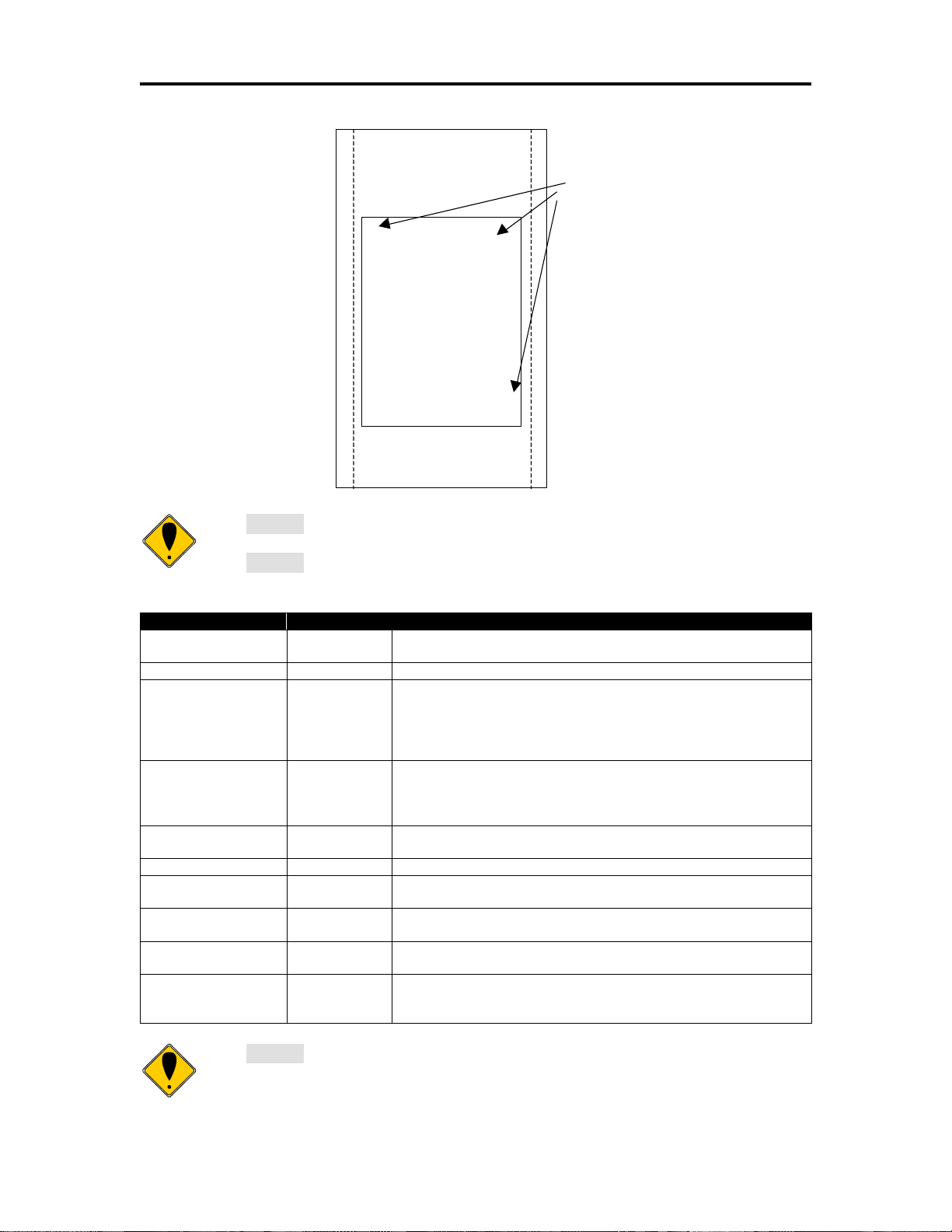
Epic 3000 Programmer’s Guide Programming Codes
Receipt or
Inserted Form
B > > > > >
A > > > > >
D > > > > >
C > > > > >
Initial entry
location
Note 1: This command saves the current right and left margin and sets
them to the maximum values for the orientation currently defined.
Note 2: During page mode definition almost all printer commands are
active. The following table lists the exceptions.
Command
Active
Action
Cash drawer
commands
Yes
Immediate action
Bell command
Yes
Immediate action
Auto cut commands
Delayed
The printer will perform a feed to cut and then operate the auto
cutter after the page is printed. The cut command may be
anywhere in the definition. If the page is printed twice, the Auto
cut command must be reissued after the first print to generate
additional cuts.
Electronic journal
station select
No
This command is like a station select and is not active. You
cannot store page mode images in the electronic journal. A
page mode command in journal station mode will exit journal
mode.
Electronic journal
entries
Yes
You can make journal entries as part of a page description.
They are saved as text and not part of the page.
Status requests
Yes
The status is returned during definition.
Printer initialize
command
Yes
Cancels page mode definition and returns the printer to standard
mode.
Set top of form
No
You must set the top of form outside of page mode. The form
position is maintained after the page is printed.
Vertical tab
No
The definition of a vertical tab is ambiguous in page mode and is
ignored.
Macro definitions
No
You can not define or delete a macro while in page mode. You
can, however, invoke a macro or stored graphic. You can not
enter page mode while in a macro definition.
Note 3: Unless specified by a page mode set page size command, the
default page size is the full paper width for about 6 inches. Printing starts
at the current paper position. The complete page definition is printed
100-14362 Rev A Page 67
Page 68

Programming Codes T480 Programmer’s Guide
excluding any blank information at the bottom of the page.
Note: The maximum printable area in the x direction is 576/203 or 3.15
inches.
Note: The maximum printable area in the y direction is 2999/203 or 14.78
inches.
Note: Only the used portion of the page is printed. That is the page length
will only include what actually has print data. See illustration below.
Function Set Print Area in Page Mode Enhanced
ASCII [ESC] [SUB] S <XO
Hexadecimal 1BH 1AH 53H <XO
Decimal <27><26><83><XO
><XOH><<YOL><YOH><WL><WH>< HL><HH>
L
><XOH><<YOL><YOH><WL><WH>< HL><HH>
L
><XOH><<YOL><YOH><WL><WH>< HL><HH>
L
IPCL None
EPOS [ESC] W
Description This command Sets the position and size of the initial area in page mode
and sub pages.
Where:
<XOL><XOH> the x direction offset Min 0
<YOL><YOH> the y direction offset Min 0
<WL><WH> the width in dots Max 540
< HL><HH> the height in dots Max 6000
This command should always be sent before or immediately after page mode is entered
to define the initial page size.
Once in page mode (after the [ESC]t command) the command can be sent multiple
times so that several different print areas, aligned in different print directions, can be
developed in the printer’s page buffer before being printed using the Print Page Mode
commands
(FF or ESC FF).
The starting position of the print area is the upper left of the area to be printed. The
Yoffset is in the y direction and is YO dots and the Xoffset is in the x direction and is XO
dots in. The length of the area to be printed in the y direction is set to H dots. The length
of the area to be printed in the x direction is set to W dots.
The set print area command may be invoked multiple times while in page mode. The
first invocation specifies the initial master page size. Following invocations will define
smaller windows within the initially defined page. If the Set page size command is not
used, the page size will default to the maximum size.
The orientation of the set print area command is always based on 0 degrees regardless
of the current orientation setting. This includes if the command is sent before the start
page mode command, after the start page mode command, or as a sub-page.
Page 68 Rev A 100-14362
Page 69
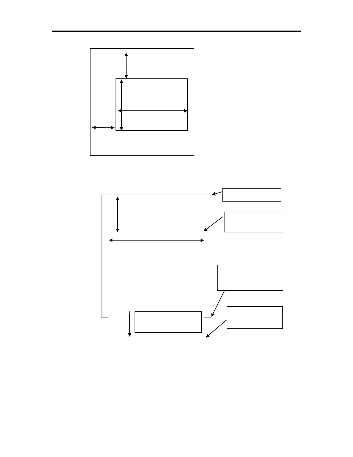
Epic 3000 Programmer’s Guide Programming Codes
Previous cut
Start of page
definition
Max width is 640 dots
End of page
definition
Cut point is after
bottom most print
data.
Cut to print offset
0.7 in or 18mm
Bottom most print data
Unused page area
is not printed
YOffset <OL><OH>
Height < H
><H
>
Width < W
><W
>
XOffset <OL><OH>
Figure 2 Page mode set printable area
100-14362 Rev A Page 69
Figure 3 Default Page mode printed area
Page 70

Programming Codes T480 Programmer’s Guide
Previous cut
Start of page
definition
Max width is 576 dots
End of page
definition
Cut point after
bottom of page
definition
Cut to print offset
0.7 in or 18mm
Bottom most print data
Unused page area
is not printed
Function Set Printed Area in Page Mode Enhanced
ASCII [ESC] [SUB] W <XO
Hexadecimal 1BH 1AH 57H <XO
Decimal <27><26><87><XO
><XOH><<YOL><YOH><WL><WH>< HL><HH>
L
><XOH><<YOL><YOH><WL><WH>< HL><HH>
L
><XOH><<YOL><YOH><WL><WH>< HL><HH>
L
IPCL None
EPOS [ESC] W
Description This command is similar Set Print Area in Page Mode command above,
however it will force the complete page to be printer rather than only what is used. It will
define sub pages, however is intended to set the initial page size.
Where:
<XOL><XOH> the x direction offset Min 0
<YOL><YOH> the y direction offset Min 0
<WL><WH> the width in dots Max(640)
< HL><HH> the height in dots Max(3000)
This command should always be sent before or immediately after select page mode
command and will define the initial page size. This command differs from the Set Print
Area in Page Mode command in that it does not allow the page to be shortened. The
complete page is printed even if it is not used.
Page 70 Rev A 100-14362
Figure 4 Defined Page mode printed area
Page 71

Epic 3000 Programmer’s Guide Programming Codes
Note: The maximum printable area in the x direction is 576/203 or 3.15
inches.
Note: The maximum printable area in the y direction is 5999/203 or 29
inches.
Note: The printed page length will only include what actually has print
data.
Function Set Print Area in Page Mode Legacy Support Command
ASCII [ESC] u <OL><OH><WL><WH>< HL><HH>
Hexadecimal 1BH 75H <OL><OH><WL><WH>< HL><HH>
Decimal <27><117><OL><OH><WL><WH>< HL><HH>
IPCL &%PS<0000><WWWW><HHHH>
EPOS [ESC] W
Description This command Sets the position and size of the printing initial area in
page mode and sub pages.
Where:
<OL><OH> the y direction offset Default(0)
<WL><WH> the width in dots Default(640)
< HL><HH> the height in dots Default(6000)
This command should always be sent before or immediately after page mode is entered
to define the initial page size.
Once in page mode (after the [ESC]t command) the command can be sent multiple
times so that several different print areas, aligned in different print directions, can be
developed in the printer’s page buffer before being printed using the Print Page Mode
commands
(FF or ESC FF).
The starting position of the print area is the upper left of the area to be printed. The
offset is in the x direction and is O dots. The length of the area to be printed in the y
direction is set to H dots. The length of the area to be printed in the x direction is set to
W dots. (Note that the Y offset is always 0)
The set print area command may be invoked multiple times while in page mode. The
first invocation specifies the final page height. Following invocations will define smaller
windows within the initially defined page. If the Set page size command is not used, the
page size will default to the maximum size.
The orientation of the set print area command is always based on 0 degrees regardless
of the current orientation setting. This includes if the command is sent before the start
page mode command, after the start page mode command, or as a sub-page.
100-14362 Rev A Page 71
Page 72

Programming Codes T480 Programmer’s Guide
Note: You can also use the [ESC]J, [ESC]M. [ESC]d and [ESC]e
commands to position the print on the page.
Note: You can also use the [ESC]J, [ESC]M. [ESC]d and [ESC]e
commands to position the print on the page.
Function Set Page Mode Entry Position
ASCII [ESC] [SUB] A <XL><XH><YL><YH>
Hexadecimal 1BH 1AH 41H<XL><XH><YL><YH>
Decimal <27><26><65><XL><XH> <YL><YH>
IPCL &%PY<XXXX><YYYY>
EPOS [ESC] W
Description This command sets the horizontal and vertical entry position to anywhere
on the page. It is only valid in page mode. If the value specified is beyond the page
boundary, the command is ignored. (X and Y refers to the current active orientation
specified by the [ESC]t command, and is not same as the page definition of X and Y.)
The X and Y positions are in dots.
Y = Yh* 256 + Yl dots from the top
X = Xh* 256 + Xl dots from the left
Function Set Page Mode Entry Position Relative
ASCII [ESC] [SUB] R <XL><XH><YL><YH>
Hexadecimal 1BH 1AH 52H <XL><XH><YL><YH>
Decimal <27><26><82><XL><XH> <YL><YH>
IPCL None
EPOS [ESC] W
Description This command sets the horizontal and vertical entry position to anywhere
on the page. It is only valid in page mode. If the value specified is beyond the page
boundary, the command is ignored. (X and Y refers to the current active orientation
specified by the [ESC]t command, and is not same as the page definition of X and Y.)
The X and Y positions are in dots.
Y = Yh* 256 + Yl dots from the current Y
X = Xh* 256 + Xl dots from the current X
Page 72 Rev A 100-14362
Page 73

Epic 3000 Programmer’s Guide Programming Codes
Note: You can also use the [ESC]J, [ESC]M. [ESC]d and [ESC]e
commands to position the print on the page.
Note: When page mode finishes printing, the left and right margins are
restored to the values before the select page mode command. All other
format changes are preserved.
Function Set Page Mode Entry Position Legacy Support
ASCII [ESC] o <XL><XH><YL><YH><F>
Hexadecimal 1BH 6FH <XL><XH><YL><YH><F>
Decimal <27><111><XL><XH> <YL><YH><F>
IPCL None
EPOS [ESC] W
Description This command sets the horizontal and vertical entry position to anywhere
on the page. It is only valid in page mode. If the value specified is beyond the page
boundary, the command is ignored. (X and Y refers to the current active orientation
specified by the [ESC]t command, and is not same as the page definition of X and Y.)
The X and Y positions are in dots.
Y = Yh* 256 + Yl dots from the top
X = Xh* 256 + Xl dots from the left
The F parameter is a flag that specifies if this command is an absolute position
command or relative to the current position. If its value is <1> the command is
processed as a relative position command, and if its value is <0> the command is
interpreted as an absolute position command.
Function Exit Page Mode
ASCII [FF] or [ESC][SUB] P
Hexadecimal 0CH or 1BH 1AH 50H
Decimal <12> or <27><26><80>
IPCL &%FF
EPOS [FF]
Description This command exits page mode definition and starts the print process. If
the printer is not in page mode, this command is treated as a normal form feed
command.
100-14362 Rev A Page 73
Page 74

Programming Codes T480 Programmer’s Guide
Note 1: If the EPIC 3000 Printer is used with programs that convert text to
graphics, the printer is slower than if the printer is sent ASCII text. The
EPIC 3000 Printer is supported by a Windows’ print driver that allows
applications to select supported fonts.
Note 2: Generally, the horizontal graphic commands provide faster print
than the APA graphic commands.
Graphic Modes
The EPIC 3000 Printer conforms to the basic definition of IBM all-points-addressable
(APA) graphic commands. It is not designed to print large quantities of graphical data.
The printer only prints graphics that are 2.5 inches wide. At this time, there is not a
graphics mode for Epson emulation.
The EPIC 3000 Printer always prints in one of the native resolutions of 104 x 96, 208 x
96, 104 x 192, or 208 x 192 dpi. To provide compatibility with the standard IBM APA
resolutions, the printer internally modifies the graphics to print as expected. The printer
converts the vertical resolution by altering the [ESC] J command (which is typically used
for vertical spacing) and adjusting it so that horizontal passes touch as expected. The
requested horizontal resolution is converted by data scaling. Because the vertical dpi of
the printer is always greater, the resulting APA graphics printed on the EPIC 3000
Printer are slightly smaller than the same graphic printed on an impact printer. All of this
is done transparently to the application; however, loss of resolution may result in some
modes. If desired the [ESC] * <m> command can be used to select the native resolution.
Standard APA Graphics
[ESC] K Print single-density graphics (60h x 72v dpi)
ASCII [ESC] K <n1> <n2>
Hexadecimal 1BH 4BH <n1> <n2>
Decimal <27> <75> <n1> <n2>
IPCL none
Description The [ESC] K <n1> <n2> command prints <n1> + 256 * <n2> bytes of
single-density graphics (60 dpi).
[ESC] L Print half-speed double-density graphics (120h x 72v dpi)
ASCII [ESC] L <n1> <n2>
Hexadecimal 1BH 4CH <n1> <n2>
Decimal <27> <76> <n1> <n2>
IPCL none
Description The [ESC] L <n1> <n2> command prints <n1> + 256 * <n2> bytes of
double-density graphics (120 dpi) at half speed, allowing full and half dots to be printed.
[ESC] Y Print full-speed double-density graphics (120h x 72v dpi)
Page 74 Rev A 100-14362
Page 75

Epic 3000 Programmer’s Guide Programming Codes
ASCII [ESC] Y <n1> <n2>
Hexadecimal 1BH 59H <n1> <n2>
Decimal <27> <89> <n1> <n2>
IPCL none
Description The [ESC] Y <n1> <n2> command prints <n1> + 256 * <n2> bytes of
double-density graphics (120 dpi) at full speed with no consecutive dots. (The mode is
generally used to print 120h by 144v dpi resolutions in two passes).
[ESC] Z Print quad-density graphics (240h x 72v dpi)
ASCII [ESC] Z <n1> <n2>
Hexadecimal 1BH 5AH <n1> <n2>
Decimal <27> <90> <n1> <n2>
IPCL none
Description The [ESC] Z <n1> <n2> command prints <n1> + 256 * <n2> bytes of quad-
density graphics (240 dpi) at half speed with no consecutive dots. (The mode is
generally used to print 240h by 144v dpi resolutions in two passes).
Extended APA Graphics
[ESC] * Print graphics in mode <m> (60h/ 120h/ 240h x 72v dpi)
ASCII [ESC] * <m> <n1> <n2>
Hexadecimal 1BH 2AH <m> <n1> <n2>
Decimal <27> <42> <m> <n1> <n2>
IPCL none
Description The [ESC] * <m> <n1> <n2> command selects one of three graphic
modes as specified by <m>.
Where <m> 0 60 dpi Full speed 8-bit slices
1 120 dpi Half speed 8-bit slices
2 120 dpi Full speed 8-bit slices
3 240 dpi Full speed 8-bit slices
4 80 dpi Full speed 8-bit slices
5 72 dpi Full speed 8-bit slices
6 90 dpi Full speed 8-bit slices
7 144 dpi Full speed 8-bit slices
8,9 Not supported
10 104 x 96 dpi 1 horizontal 1 vertical pass
11 208 x 96 dpi 2 horizontal 1 vertical pass
12 104 x 192 dpi 1 horizontal 2 vertical passes
13 208 x 192 dpi 2 horizontal 2 vertical passes
15,16 Not supported
[ESC] ? Reassign graphic mode
ASCII [ESC] ? <m> <n>
Hexadecimal 1BH 3FH <m> <n>
Decimal <27> <63> <m> <n>
100-14362 Rev A Page 75
Page 76

Programming Codes T480 Programmer’s Guide
Note: Modes 11 through 13 are designed to support horizontal graphics
and not intended for APA graphics.
Note: Unidirectional print should be canceled before normal text is printed.
Print time is slowed if it is not canceled.
IPCL none
Description The [ESC] ? <m> <n> command reassigns graphic mode <m> to
resolution <n>. Possible values for <m> are K, L, Y, or Z. Resolutions, <n>, are zero to
seven as follows:
Where <m> 0 60 dpi Full speed 8-bit slices Default for K
1 120 dpi Half speed 8-bit slices Default for L
2 120 dpi Full speed 8-bit slices Default for Y
3 240 dpi Full speed 8-bit slices Default for Z
4 80 dpi Full speed 8-bit slices
5 72 dpi Full speed 8-bit slices
6 90 dpi Full speed 8-bit slices
7 144 dpi Full speed 8-bit slices
10 104 x 96 dpi 1 horizontal, 1 vertical pass
11 208 x 96 dpi 2 horizontal, 1 vertical pass
12 104 x 192 dpi 1 horizontal, 2 vertical passes
13 208 x 192 dpi 2 horizontal, 2 vertical passes
[ESC] U <1> Select unidirectional print
ASCII [ESC] U <1>
Hexadecimal 1BH 55H 01H
Decimal <27> <85> <1>
IPCL &%GU
EPOS ESC] U <1>
Description The [ESC] U <1> command prints all data in unidirectional print mode to
improve line to line registration for graphical data.
[ESC] U <0> Select bidirectional print
ASCII [ESC] U <0>
Hexadecimal 1BH 55H 00H
Decimal <27> <85> <0>
IPCL &%GB
EPOS [ESC] U <0>
Description The [ESC] U <0> command prints all data in bi-directional, logic-seeking
print mode. (This command has no affect on the printer but is provided for compatibility
with impact and inkjet printers.
Page 76 Rev A 100-14362
Page 77

Epic 3000 Programmer’s Guide Programming Codes
Note 1: If the printer is configured for Gray scale paper, this command is
used for gray scale graphics.
Note 1: Red, green, and blue pixels set to one at the same location result
in a white dot, while red, green, and blue pixels set to zero form a black
dot. For black print, one represents a black dot and zero represents a
white dot.
Note 2: More than one color may be set at a time, for example, setting the
color to six would set green and blue simultaneously
Horizontal Graphics
The EPIC 3000 Printer supports graphics sent as horizontal scan lines. Individual scan
lines of graphic data are sent to the printer one line at a time. Although the EPIC 3000
Printer only supports two colors (black and white), the horizontal graphic command
interface gives color or gray scale support for printer graphics. Color support is provided
to establish a full color standard for future printers. Color data is sent in one of three
color planes. Typically, a red plane or scan line is sent, then green and blue. Gray scale
support is provided by using the red, green and blue as gray levels. The sequence of
lines defines one row of dots that is printed on the paper.
The horizontal graphic commands do not include resolution information. Therefore, only
once before sending graphics data, set the graphics resolution by sending the [ESC] *
command with a zero length (no data). The graphic resolution sets the internal graphic
mode of the printer. The printer stays in graphic mode until it is changed by another
command. Note that the bar code generation and other graphic commands change
graphics mode. The format of the horizontal graphic command follows.
[ESC] h Process horizontal graphics data
ASCII [ESC] h <color> <length> <format> <data>
Hexadecimal 1BH 68H
Decimal <27> <104>
IPCL None
EPOS None
Description The [ESC] h <color> <length> <format> <data> command processes
horizontal graphic data, where <color> is a byte that specifies the color of the data being
sent.
<color> = 0 Use Previously Selected Color
1 Red Gray
2 Green or Light Gray
4 Blue Dark Gray
<length> = byte specifying the length of the data including the format byte, ranging
from 0 to 254 (255 is reserved for future use.)
<format> = byte specifying the format of the graphics data.
0 for raw data
100-14362 Rev A Page 77
1 for bit wise RLE compression
8 for byte wise RLE compression
Page 78

Programming Codes T480 Programmer’s Guide
Note 1: Only modes 10 thorough 13 should be selected for horizontal
graphics.
Note 2: Graphic data is committed to paper when more than 12 dot rows
have been transmitted to the printer. If less than 12 dot rows have been
sent, they are not printed until the line is terminated (i.e. a line feed
command is sent). To make graphics faster to send and smaller to store,
several algorithms are included with the graphic command to compress
the data.
254 for difference compression
255 for same as previous scan line data
<data> = the data bytes that define the graphics to be printed.
[ESC] * Set horizontal graphic mode
ASCII [ESC] * <m> <0> <0>
Hexadecimal 1BH 2AH <m> <0> <0>
Decimal <27> <42> <m> <0> <0>
IPCL none
Description The [ESC] * <m> <0> <0> command selects one of the three graphic
modes specified by <m>. The two bytes after the mode must be zero.
Where <m> 0,2,3,4,5,6,7 Standard Graphic Modes (See ESC * command
documentation in previous section.)
8,9 Not supported
10 102 x 102dpi 1 horizontal, 1 vertical pass
11 203 x 102 dpi 2 horizontal, 1 vertical pass
12 102 x 203 dpi 1 horizontal, 2 vertical passes
13 203 x 203 dpi 2 horizontal, 2 vertical passes
14,15,16 Not supported
Example Command Comment
[ESC] * <10> <0> <0> Set resolution to 100x96 dpi.
[ESC] h <1> <9> <0> <eight data bytes> Send 8-bytes red pixels.
[ESC] h <2> <9> <0> <eight data bytes> Send 8-bytes green pixels.
[ESC] h <3> <9> <0> <eight data bytes> Send 8-bytes blue pixels.
LF Send line feed to force print of any buffered data not yet printed.
Graphics Compression
Although the printer compression algorithms are documented, it is recommended that
our Windows’ printer driver be used to generate a graphic image. Our Windows’ printer
driver selects the best compression method to use on a scan line by scan line basis.
The print driver can be directed to print to file, creating a .prn file. When creating a .prn
file, it is recommended that the Start/End Doc settings be cleared in the Start/End Doc
tab of the printer properties page. After the .prn file is created, it can be read and sent to
the printer by the host application.
Bit wise RLE. In bit wise RLE compression, the Most Significant Bit (MSB) compression
of each data byte denotes if the compressed data represents one or zero bits. Bits zero
Page 78 Rev A 100-14362
Page 79

Epic 3000 Programmer’s Guide Programming Codes
through six indicate how many bits are represented as a one or zero. A 34 Hex (34H)
represents 34H bits set to zero. A 97H represents 17H bits set to one.
[ESC] h <1> <5> <1> <34H> <97H> <8fH> <09H>
Byte wise RLE. In byte wise RLE compression, data is represented in byte
Compression pairs. The first byte is a count, and the second is the graphics data. The
graphics data byte is repeated the number of times represented by the count byte.
[ESC] h <1> <5> <8> <09H> <ffH> <02H> <55H>
Where <09H> <ffH> means repeat ffH nine times and <02H> <55H> means repeat 55H
two times.
Difference Compression. In difference compression, data is represented in byte pairs.
In compression, the first byte is an index into the byte stream, as it would exist if sent in
an uncompressed format. The second byte is the data that is different in the new scan
line data. Think of compression mode as, “The scan line is the same as the previous
except for the byte at a specific position.”
[ESC] h <1> <5> <254> <03H> <d5H> <0bH> <51H>
Where <03H> <d5H> means use the previously transmitted scan line data but change
byte 3 to a d5H and change byte 11 (0bH) to a 51H.
Same-as-previous Compression. In same-as-previous compression, the command
does not contain any graphics data. The command specifies that the printer is to use the
previous scan line data for the current scan line.
[ESC] h <1> <1> <255>.
100-14362 Rev A Page 79
Page 80

Programming Codes T480 Programmer’s Guide
Note: Where as the printer will process and print an 8 bit or 24 bit color
image, the actual print will be Monochrome, two color or grayscale. The
printer will translate the color image based on its own rules so the resulting
image may not be as you intended. In addition, the amount of data in an 8
or 24 bit color bitmap is extensive. The time required to transfer the image
will be much longer than the same monochrome image. You are much
better off converting the image to Monochrome or 16 colors within your
application.
Note: A Bitmap graphic file may also be written to the EPIC 3000’s file
system using the file system commands. It can then be printed by the
[ESC][FS]P command. In this case, it is not saved in the temporary file so
the [ESC][FS]p does not work.
Bitmap Graphics File Support
The EPIC 3000 printer supports direct printing of Monochrome, 4 bit-16 color, 8bit-256
color, 24bit True color bitmap files. The image may be directly printed or saved
temporarily and scaled at 1 to 1 or 2 to 1. Printing in Monochrome, two color or gray
scale is supported based on paper selection.
Color bitmaps are converted to a grayscale representation of its luminance by adding
together 30% of the red value, 60% of the green value, and 10% of the blue value.
These weights are predefined in the printer and are close to the industry standard 30%,
59% and 11%. Two color print is based on the luminance with color weighting of the
selected paper color. Grayscale print is based only on the luminance value.
[ESC] [FS] Print Bitmap File Record
ASCII [ESC] [FS] <Bitmap file data>
Hexadecimal 1BH 1CH
Decimal <27> <28>
IPCL None
EPOS None
Description The [ESC][FS] command is actually a group of commands intended to
print graphics. All bit map files begin with “BM” so when the bitmap data is sent after the
[ESC][FS], the command is really [ESC][FS] B, This command accepts Monochrome
and 16 color bitmap files and saves it as a temporary RAM file. The image may then be
printed with the [ESC][FS]p command or saved in the file system with and [ESC][FS]S
command.
[ESC] [FS] p Print bitmap image buffer.
ASCII [ESC] [FS] p<Scale>
Hexadecimal 1BH 1CH 70H
Decimal <27> <28><112>
IPCL None
Page 80 Rev A 100-14362
Page 81

Epic 3000 Programmer’s Guide Programming Codes
Note: The temporary buffer is also used for various other commands. If
the data in the buffer is not a bitmap graphic, it won’t be printed by this
command.
Note: The [ESC][FS] P command looks for graphic files defined by the
[ESC][FS] S command first. If the EPIC 3000 cannot find a .bgp
EPOS None
Description The [ESC][FS] p command prints a bitmap image in the temporary buffer.
Where Scale 0 = one to one.
1 = twice the width
2 = Twice the height
3 = Twice the height and width.
The intent of this command is to allow a bitmap file to be loaded into the EPIC 3000 and
printed scaled up to 2 to 1. Use the [ESC] [FS] <Bitmap file data> command to load the
bitmap image and the [ESC][FS] p to print it.
[ESC] [FS] P Print Bitmap File Print
ASCII [ESC] [FS] P<Bitmap file data>
Hexadecimal 1BH 1CH 50H
Decimal <27> <28><80>
IPCL None
EPOS None
Description The [ESC][FS] P command accepts Monochrome, 16 color, 256 color and
24bit color bitmap files and prints them immediately bit for bit with no scaling.
[ESC] [FS] P Print Saved Bitmap File Print
ASCII [ESC] [FS] P <Scale><File Name><0>
Hexadecimal 1BH 1CH 50H <Scale><File Name><0>
Decimal <27> <28><80><Scale><File Name><0>
IPCL None
EPOS None
Description The [ESC][FS] P command followed by a value that is not ‘B’ selects a
scale, retrieves a graphic file named in the File Name field and prints it at the selected
scale. This graphic file must previously have been defined and saved by the [ESC][FS]
command and the [ESC][FS]S command or by writing a bitmap file to the file system with
file system commands.
Where Scale 0 = one to one.
1 = twice the width
2 = Twice the height
3 = Twice the height and width.
100-14362 Rev A Page 81
Page 82

Programming Codes T480 Programmer’s Guide
command, it will search for a .bmp file. If there are two files with the same
root name, the .bgp file will be processed.
Note: The [ESC][FS] S command erases the RAM file so the [ESC][FS] p
will no longer print the saved image.
Note: This command followed by a zero length file name will flush the
stored graphic image.
[ESC] [FS] S Save Bitmap File Print
ASCII [ESC] [FS] S <File Name><0>
Hexadecimal 1BH 1CH 53H <File Name><0>
Decimal <27> <28><83> ><File Name><0>
IPCL None
EPOS None
Description The [ESC][FS] S accepts a file name and saves the previously defined
bitmap file in the RAM file system to the Flash file system. If the file already exists, the
existing file will be erased.
User Store (Graphic Save)
The EPIC 3000 Printer maintains a 16K (16384 bytes) section of flash memory and up to
192K of extended flash memory to save user information. The information can be either
macros or user-defined characters. These groups of data are indexed by name, and may
be called up at any time after they are stored. See the sections on Macros and Userdefined Characters for definitions of these functions.
To allow the host application to maintain these groups of data, a series of user store
maintenance commands are available. As referenced earlier in this manual, the user can
define a limited number of custom characters and define a macro. These
character/macro definitions can also be saved in user store. However, only one
character definition and one macro can be active at any time. One macro and one userdefined character definition can be flagged to load and run at startup. If a flag is set, the
printer will automatically process the macro and/or load the user-defined character set at
initialization.
Because user store is intended to be loaded only a few times and then printed as part of
normal operation, the programmer must take some care during the definition phase.
The programmer must assume the responsibility to assure the 16K buffer size is not
exceeded. User store can save macros and user-defined character sets.
When the basic user store is full, it can be moved to extended user store. Individual
items in the extended user store can not be erased. The entire extended user store must
be erased all at once. You may place two items in user store with the same name and
the last defined item will be used.
Page 82 Rev A 100-14362
Page 83

Epic 3000 Programmer’s Guide Programming Codes
Defining Macros
Macros can be defined two ways. The first is by using the begin and end named macro
commands. These commands start the recording process and automatically save the
macro when it is complete. The macro data is not processed, as it is sent to the printer.
Function Begin named macro record
ASCII [ESC] [US] b <Name..> <0>
Then send the data to be recorded. The printer does not process the
data. The terminating <0> may be replaced with an & or redefined. See
[ESC] [EM]T<n> or &%UT<n> on page 88.
Function End name macro record
ASCII [ESC] [US] e <Name..> <0>
The second way to define macros is to use [ESC] g commands to define
the macro, and then the save macro data command to save the data.
The terminating <0> may be replaced with an & or redefined. See [ESC]
[EM]T<n> or &%UT<n> on page 88.
Function Start macro record
ASCII [ESC] g <1>Then send the data to be recorded. (The data is processed
and printed).
Function Stop macro record
ASCII [ESC] g <2>Then save the macro.
Function Save macro data
ASCII [ESC] [US] m <Name..><0>
Saving User-defined Characters. To save user-defined characters, first
define the character set.
Function Define user-defined characters
ASCII [ESC] = <y> <c1> <c2> [x1 d1 … d(y x x
Second, save the definition in the nonvolatile flash memory with the
appropriate command.
Save the definition. Note the "Save user-defined characters" command
saves all three character definitions.
Function Save user-defined characters
ASCII [ESC] [US] c <Name..> <0>
Third, load the character set or load and run the macro.
To restore the character definitions, issue a load item command with the
name of the character set to be loaded.
The terminating <0> may be replaced with an & or redefined. See [ESC]
[EM]T<n> or &%UT<n> on page 88.
)] … [xk d
1
… d(y x xk)]
1
100-14362 Rev A Page 83
Page 84

Programming Codes T480 Programmer’s Guide
Note: A configuration option is available that locks the user store data.
The configuration option prevents the occurrence of new user store data
operation until the lock is manually reset and accidental deletion of the
saved information. The user-defined character buffer and/or user data
buffer may be redefined and used but cannot be stored.
Function Load item from user store
ASCII [ESC] [US] l <Name..> <0>
If the item referenced is a user-defined character set, it is loaded into the
current definition. If it is a macro, it is loaded into the macro buffer. It is
not processed or printed.
To help maintain the user-store area, the following commands can be
used.
The terminating <0> may be replaced with an & or redefined. See [ESC]
[EM]T<n> or &%UT<n> on page 88.
Function Flag as a start-up macro
ASCII [ESC] [US] s <Name..> <0>
The [ESC] [US] s <Name..> <0> command flags the referenced item to be
processed at startup. No more than one user character definition and user data item
may be flagged.
The terminating <0> may be replaced with an & or redefined. See [ESC]
[EM]T<n> or &%UT<n> on page 88.
Function Remove item from user store
ASCII [ESC] [US] e <Name..> <0>
The [ESC] [US] e <Name..> <0> command removes an item from user
store and frees up its space. The terminating <0> may be replaced with
an & or redefined. See [ESC] [EM]T<n> or &%UT<n> on page 88.
Function Flush information from user store
ASCII [ESC] [US] f ALL <0> Base User Store
or [ESC] [US] f EXT <0> Extended User Store.
Description The [ESC] [US] f ALL <0> command clears all of the information to the
user store and frees the data space. The [ESC] [US] f EXT <0> command clears all of
the information in the extended the user store.
The terminating <0> may be replaced with an & or redefined. See [ESC] [EM]T<n> or
&%UT<n> on page 88.
Function Report on user store
ASCII ESC] [US] q <0>
Description The [ESC] [US] q <0> prints or returns information about the contents of
and available space in user store.
The terminating <0> may be replaced with an & or redefined. See [ESC] [EM]T<n> or
&%UT<n> on page 88.
Page 84 Rev A 100-14362
Page 85

Epic 3000 Programmer’s Guide Programming Codes
User-Store Commands
Function Begin named macro record
ASCII [ESC] [US] b <Name..> <0>
Hexadecimal 1BH 1FH 62H
Decimal <27> <31> <98>
IPCL &%UB <Name..> <0>
EPOS none
Description The [ESC] [US] b <Name..> <0> command erases the current macro,
initializes the macro buffer structure, and redirects the following data to the macro buffer.
It uses the <Name..> field as a reference. If the name already exists in the flash user
store, the command is ignored. The command must be followed by the "End name
macro record" command with the same name. If the data that follows is larger than the
macro buffer (about 16K), the macro definition is terminated without saving any data.
The terminating <0> may be replaced with an & or redefined. See [ESC] [EM]T<n> or
&%UT<n> on page 88.
Function End named macro record
ASCII [ESC] [US] e <Name..> <0>
Hexadecimal 1BH 1FH 65H
Decimal <27> <31> <101>
IPCL &%UG <Name..> <0>
EPOS none
Description The [ESC] [US] e <Name..> <0> command ends the macro record
operation and saves the macro to flash. It uses the <Name..> field to verify the
command end and must match the "Begin named macro record" command. If the name
already exists in the flash user store or the macro memory is exceeded, the command is
valid, and the <Name..> field prints. If there is not enough room in the flash user store
for the macro, the save is not performed, but the macro buffer is valid.
The terminating <0> may be replaced with an & or redefined. See [ESC] [EM]T<n> or
&%UT<n> on page 88.
Function Save macro data in user store
ASCII [ESC] [US] m <Name..> <0>
Hexadecimal 1BH 1FH 6DH
Decimal <27> <31> <109>
IPCL &%UM <Name..> <0>
EPOS [GS] -…<Name..> <0> is from one to 15 characters and must be null
terminated.
Description The [ESC] [US] m <Name..> <0> command saves the current macro
buffer structure into the flash user-store area. It uses the <Name..> field as a reference
name. If the name already exists in the flash user store, the command does not store
the data.
The terminating <0> may be replaced with an & or redefined. See [ESC] [EM]T<n> or
&%UT<n> on page 88.
Function Save user-defined characters
ASCII [ESC] [US] c <Name..> <0>
Hexadecimal 1BH 1FH 63H
Decimal <27> <31> <99>
100-14362 Rev A Page 85
Page 86

Programming Codes T480 Programmer’s Guide
IPCL &%UC <Name..><0>
EPOS [GS] 6<Name..> <0> is from one to 15 characters and must be null
terminated.
Description The [ESC] [US] c <Name..> <0> command saves the current userdefined character structure in the flash user-save storage area. It uses the<Name..>
field as a reference. If the name already exists in the flash user store, the command will
not store the data.
The terminating <0> may be replaced with an & or redefined. See [ESC] [EM]T<n> or
&%UT<n> on page 88.
Function Load item from user store
ASCII [ESC] [US] l <Name..> <0>
Hexadecimal 1BH 1FH 6CH
Decimal <27> <31> <108>
IPCL &%UL <Name..> <0>
EPOS [GS] 0<Name..> <0> is from one to 15 characters and must be null
terminated.
Description The [ESC] [US] l <Name..> <0> command loads the referenced item into
the appropriate structure. If the item referenced is a user-defined character set, it is
loaded into the current user-character definition, which does not affect the active state of
user-defined characters. If it is a macro, it is loaded into the macro buffer, but it is not
inserted into the data stream. [ESC] g <0> inserts the macro buffer into the data stream.
If the named item does not exist, the command does nothing.
The terminating <0> may be replaced with an & or redefined. See [ESC] [EM]T<n> or
&%UT>n> on page 88.
Function Run macro data from user store
ASCII [ESC] [US] r <Name..> <0>
Hexadecimal 1BH 1FH 72H
Decimal <27> <31> <114>
IPCL &%UR <Name..> <0>
EPOS [GS] 0<Name..> <0> is from one to 15 characters and must be null
terminated.
Description The [ESC] [US] r <Name..> <0> command loads the referenced macro
into the macro buffer. The macro buffer is then inserted into the data stream. If the
named item does not exist or is not a macro, nothing happens.
The terminating <0> may be replaced with an & or redefined. See [ESC] [EM]T<n> or
&%UT<n> on page 88.
Function Flag item as a start-up macro
ASCII [ESC] [US] s <Name..> <0>
Hexadecimal 1BH 1FH 73H
Decimal <27> <31> <115>
IPCL &%US <Name..> <0>
EPOS [GS] 0<Name..> <0> is from one to 15 characters and must be null
terminated.
Description The [ESC] [US] s <Name..> <0> command flags the referenced item to
be processed at startup. Only one user character definition and one macro may be
flagged to run at startup.
Page 86 Rev A 100-14362
Page 87

Epic 3000 Programmer’s Guide Programming Codes
Note: If a character definition is loaded at startup, it is automatically made
active.
The terminating <0> may be replaced with an & or redefined. See [ESC] [EM]T<n> or
&%UT<n> on page88.
Function Delete item from user store
ASCII [ESC] [US] d <Name..> <0>
Hexadecimal 1BH 1FH 64H
Decimal <27> <31> <100>
IPCL &%UD <Name..> <0>
EPOS [GS] 1 <Name..> <0> is from one to 15 characters and must be null
terminated.
Description The [ESC] [US] d <Name..> <0> command removes an item from user
store and frees up space. If the item does not exist, the command does nothing.
The terminating <0> may be replaced with an & or redefined. See [ESC] [EM]T<n> or
&%UT>n> on page 88.
Function Transfer all items from user store to extended user store.
ASCII [ESC] [US] t <0>
Hexadecimal 1BH 1FH 74H
Decimal <27> <31> <116>
IPCL &%UX <0>
EPOS None
Description This command transfers the information in the base 16K user store to the
extended user store. The base user store is erased if the transfer was successful.
The terminating <0> may be replaced with an & or redefined. See [ESC] [EM]T<n> or
&%UT>n> on page 88.
Function Flush information from user store or extended user store
ASCII [ESC] [US] f ALL <0> User Store.
Or [ESC] [US] f EXT <0> Extended User Store.
Hexadecimal 1BH 1FH 66H 00H
Decimal <27> <31> <102> <0>
IPCL &%UF
EPOS [GS] 5
Description The [ESC] [US] f ALL <0> command clears all entries in user store and
frees the data space. It must have the name, “ALL” (in uppercase) attached. If “EXT” is
substituted for “ALL”, extended user store (If any) is cleared.
The terminating <0> may be replaced with an & or redefined. See [ESC] [EM]T<n> or
&%UT>n> on page 88.
Function Report on user store
ASCII [ESC] [US] q <0> Print a user store report
Or [ESC] [US] ? <0> Return a formatted user store report
Hexadecimal 1BH 1FH 71H
100-14362 Rev A Page 87
Page 88

Programming Codes T480 Programmer’s Guide
Note: The report is also printed as part of the configuration report.
Decimal <27> <31> <113>
IPCL &%UQ <Name..> <0>
EPOS [GS] 3
Description The [ESC] [US] q <Name..> <0> command prints a status report. The file
name is ignored and may be omitted. The NUL must be present. The intention of the
command is to aid in macro development.
The terminating <0> may be replaced with an & or redefined. See [ESC] [EM]T<n> or
&%UT<n> on page 88.
Function Redefine User Store Termination Character
ASCII [ESC] [EM] T <n>
Hexadecimal 1BH 19H 54H <n>
Decimal <27> <25> <84> <n>
IPCL &%UT <n>
EPOS None
Description This command allows the terminator used to signal the end of the name
field in User Store commands to be modified. The value of <n> is used (in addition to
the <0>) for the terminator. The value of n may be from 0 to 255.
The default value for the second terminator is &. If this command redefines the
terminator to something other than &, the & will no longer function.
Example If &%UT% were sent to the printer, the user store command to run macro
"Demo" would be &%URDemo%.
User Macros
The user macro feature works by inserting the macro data buffer into the printer data
stream when the print user-store data command is encountered.
Macros can be any data normally sent to the printer including graphics. (Note: user-store
maintenance and inquire commands may not be included in the macro definitions.) The
printer stores macro data in a RAM-based storage buffer as it is received and
processed. The storage buffer may then be saved to a flash-based user store or inserted
into the print data stream. If a macro is recalled from user store, it is expanded into the
macro buffer and replaces whatever is currently there.
Programming Considerations
The flash (nonvolatile) memory has a limited number of write cycle operations.
Consequently, the number of saves should be limited. The buffer should not be saved on
a transaction by transaction basis, but rather a maximum of once per day.
The buffer is initially about 16K8 bytes long. All commands9 and print data are placed in
the buffer and must be included in the size limits. The printer does not indicate when the
buffer is full. The application must make sure that the buffer is not overfilled. The printer
8
The actual buffer is smaller because of the overhead.
9
IPCL commands are converted by the printer into an equivalent [ESC] code and then placed in
the save buffer. The equivalent [ESC] code should be used to calculate the size of the save
buffer data.
Page 88 Rev A 100-14362
Page 89

Epic 3000 Programmer’s Guide Programming Codes
simply stops saving information when it is full. As the buffer fills, the input data is printed
normally. The effect of the macro start command is to clear the buffer and to start to
save the input data. The macro stop command stops saving data and initializes internal
pointers for the next print. To store the data in the nonvolatile flash, it must be named
and saved by one of the user-store save commands.
When the macro buffer is inserted into the data stream, configuration commands (like
font or pitch changes) remain in effect after the macro is processed. Illegal commands
are placed in the buffer and take up space.
Horizontal color graphics should be sent to the printer compressed. If the data is not
compressed, it is saved in the macro buffer. If the buffer is saved into the user-store
nonvolatile flash, there must be enough room in the user store for all of the data. As
user-store space is used, the macro buffer will be larger than the available space in user
store. Only the used space is saved, but it is possible to define a macro that does not fit
in the remaining user-store space.
100-14362 Rev A Page 89
Page 90

Programming Codes T480 Programmer’s Guide
Note: The [ESC] g <3> command is supplied for compatibility with the
Series 80PLUS and 90PLUS printers.
[ESC] g <0> Process user macro
ASCII [ESC] g <0>
Hexadecimal 1BH 67H 00H
Decimal <27> <103> <0>
IPCL &%GP
EPOS [ESC] g <0>
Description The [ESC] g <0> command prints the user-store data buffer.
[ESC] g <1> Start macro record
ASCII [ESC] g <1>
Hexadecimal 1BH 67H 01H
Decimal <27> <103> <1>
IPCL &%GS
EPOS ESC] g <1>
Description The [ESC] g <1> command clears the user-store data buffer and begins
recording data. The next 2000 bytes (including characters and commands) are
recorded.
[ESC] g <2> Stop macro record
ASCII [ESC] g <2>
Hexadecimal 1BH 67H 02H
Decimal <27> <103> <2>
IPCL &%GE
EPOS [ESC] g <2>
Description The [ESC] g <2> command stops recording user-store data information.
The buffer is not saved into the nonvolatile memory.
[ESC] g <3> Stop macro record and save
ASCII [ESC] g <3>
Hexadecimal 1BH 67H 03H
Decimal <27> <103> <3>
IPCL &%GW
EPOS [ESC] g <3>
Description The [ESC] g <3> command stops recording graphic save information.
The buffer is saved into the user-store nonvolatile memory under the name,
"ESCg3_Save"
Page 90 Rev A 100-14362
Page 91

Epic 3000 Programmer’s Guide Programming Codes
Bar Codes
The EPIC 3000 Printer supports the ability to print bar codes. The printer offers a
number of formats as defined below. The host does not need to form the graphic image
for these bar codes. The host need only send the printer the information to be bar coded
and a graphic is generated by the printer. In some cases, a check character is required
by the format. In most cases, the printer generates the check character and inserts it
correctly in the format. The printer uses internal graphic modes to form bar code images,
and the images are adjusted for ink bleed. In general, the bar codes generated by
sending graphic data to the printer are not as readable as the bar codes the printer
generates. Bar codes are printed at a 203 x 203 resolution.
Barcodes may be printed horizontally or vertically (using page mode).
Function Print bar code
ASCII [ESC] b <n> {information} [NUL]
Hexadecimal 1BH 62H <n> ... 03H
Decimal <27> <98> <n> ... <3>
IPCL &%25 ... [CR] Interleaved 2 of 5
&%39 ... [CR] Code 39
&%12 ... [CR] Code 128
&%28 .<m1> <m2> Code 128 (allows a two character length,
preceding the information)
&%UP ... [CR] UPC A
&%UE ... [CR] UPC E
&%EA … [CR] EAN-13
&%E8 ... [CR] EAN-8
&%93 … [CR] Code 93
&%CB .. [CR] Codabar
Description The [ESC] b <n> {Bar Data} [NUL] command prints information as a bar
code. The bar data is terminated with an [ETX], [CR], [LF] or [NUL].
An alternate Format is provided if control characters can be part of the barcode data.
The [ESC] b <n><LL> <LH>{ Bar Data } command prints information as a bar code.
The <LL> <LH>parameters make up a 16 bit length of bar data as follows:
Length = (LH * 256) + LL.
An alternate format is provided that allows only a single character length for some bar
codes.
The [ESC] b <n><LL>{ Bar Data } command prints information as a bar code.
The <LL> parameters make up a 8 bit length of bar data as follows:
Length = LL.
If a start code is to be specified , The following format may be required.
The [ESC] b <n><S>{ Bar Data } [NUL] command prints information as a bar code.
<S> indicates the start code and data up to the [NUL] is the bar data.
100-14362 Rev A Page 91
Page 92

Programming Codes T480 Programmer’s Guide
Where n =
0 Interleaved 2 of 5 Numeric (0-9) only; must be even number of digits
1 Code 39 26 uppercase letters (A-Z); 10 digits (0-9)
2 Code 128 Three sets of 106 different characters
3 UPC A Numeric (0-9) only; 11 digits
4 EAN-13 Numeric (0-9) only; 12 digits
5 UPC E Numeric (0-9) only; 11 digits
6 EAN-8 Numeric (0-9) only; 7 digits
7 Code 93 26 letters; 10 digits (0-9); and 7 special Characters
8 Codabar 10 digits (0-9); 4 start/stop characters,
A, B, C, and D; and 6 special characters.
9 PDF-417 2D alpha Numeric (16bit length) (See notes below)
10 PDF-417 2D alpha Numeric (NUL term.) (See notes below)
11 EAN-128 GS-1 code 128 Alpha Numeric
12 EAN-14 Numeric (0-9) only 13 digits
13 ITF-14 GS-1 Numeric (0-9) only 13 digits
14 Code 49 2D alpha Numeric (NUL term.)
15 Maxicode 2D alpha Numeric (16bit length) (See notes below)
16 Maxicode 2D alpha Numeric (NUL term.) (See notes below)
17 Code16K 2D alpha Numeric (NUL term.)
18 RSS -14 See GS1 Databar barcode definitions below
19 RSS -14 Truncated “
20 RSS Limited “
21 RSS Stacked “ No HRI will be printed
22 RSS Stacked Omni “ No HRI will be printed
23 RSS Expanded “
24 RSS Expanded Stacked “ No HRI will be printed
25 QRCode 2D alpha Numeric (16bit length) (See notes below)
26 QRCode 2D alpha Numeric (NUL term.) (See notes below)
27 Data Matrix 2D alpha Numeric (16bit length) (See notes below)
28 Data Matrix 2D alpha Numeric (NUL term.) (See notes below)
29 Aztec 2D alpha Numeric (16bit length) (See notes below)
30 Aztec 2D alpha Numeric (NUL term.) (See notes below)
31 Aztec Rune 2D Numeric (NUL term.) (3 digits representing 0-255)
32 Code One 2D alpha Numeric (NUL term.)
33 MicroPDF-417 2D alpha Numeric (16bit length) (See notes below)
34 MicroPDF-417 2D alpha Numeric (NUL term.) (See notes below)
36 Micro QRCode 2D alpha Numeric (16bit length) (See notes below)
37 Micro QRCode 2D alpha Numeric (NUL term.) (See notes below)
COMPOSITE Barcodes
Composite data
64 Secondary Data GS-1 Alpha Numeric (NUL term.)
Linear Barcode data
65 UPC A Numeric (0-9) only; 11 digits
66 UPC E Numeric (0-9) only; 11 digits
67 EAN-8,13,14 Numeric (0-9) only; 7,12, or 13 digits
68 EAN 128 GS-1 code 128 Alpha Numeric
69 RSS -14 See GS1 Databar barcode definitions below
70 RSS -14 Truncated “
71 RSS Limited “
Page 92 Rev A 100-14362
Page 93

Epic 3000 Programmer’s Guide Programming Codes
Note1: You may print barcodes in page mode. If you rotate these
barcodes 90 or 180 you can get significantly longer barcodes.
Note2: A [CR], [LF] or [NUL] may also be used in place of the [NUL] to
end the bar code data field.
Note 3: Only information that is usable in a particular bar code will be
printed.
Note: Any values greater than 255 will be converted into a space (0x20).
Note: In UTF8 or UTF16 modes all data is assumed to be UTF encoded.
72 RSS Expanded “
73 RSS Stacked “ No HRI will be printed
74 RSS Stacked Omni “ No HRI will be printed
75 RSS Expanded Stacked “ No HRI will be printed
Barcodes and Code Pages
In ASCII mode the barcode data is not translated by the active code page. In general
barcode data is numeric (0-9) or alpha numeric (0-9 and A-Z). Some barcodes support
additional characters and are defined by the barcode specification.
Barcodes and Unicode
In Unicode mode, the printer can accept character values from 0 to 65535. In general
barcode data is generally numeric (0-9) or alpha numeric (0-9 and A-Z) and are limited
to values from 0-127. Some barcodes support additional characters as defined by the
barcode specification, however, only character values from 0 to 255 will be used for
barcodes. Any barcode character translations must be done by the host application.
Depending on the Unicode mode, values from 128 to 255 may be required to be
encoded in UTF before they are sent to the printer.
100-14362 Rev A Page 93
Page 94

Programming Codes T480 Programmer’s Guide
Note: In extended mode the printer will automatically convert extended
characters to the character pair equivalent. The HRI will print the
extended character not the character pair.
Linear Barcodes
Code-39 and Code-39 Extended
Function Code-39
ASCII [ESC] b <1> {information} [NUL]
Hexadecimal 1BH 62H <1> ... 03H
Decimal <27> <98> <1> ... <3>
[ESC] b <1> TransAct[NUL]
Note: Case conversion to upper case.
Figure 5 Code 39 Example
Code 39 is an alphanumeric bar code. It is a discrete, self-checking, variable-length
code. The printer prints the complete data field. The number of characters that can be
printed depends on the bar width scaling. There are two modes of operation for the
Code 39 barcodes. The first is in a variable length format. In this mode all characters
sent to the printer will be printed up to the termination character. Only 0-9, A-Z -, period,
and space may be printed. $, %, +, and / Characters may be used as escape characters
for full 128 character support. If illegal characters are passed to the printer, they are
converted to legal codes. (For example, a would be converted to A).
Function Code-39 Extended
ASCII [ESC] b <1><L>{information}
Hexadecimal 1BH 62H <1><L>{ ...
Decimal <27> <98> <1><L>{ ...
[ESC] b <1><8>TransAct
Note: Extended character support however the
barcode is much denser and harder to read.
Figure 6 Code 39 Extended Example
In full 128 character mode, the printer will encode the full 128 character set. In this
mode, the first character received must be the length. IE. [ESC]b<1><L>… where L
specifies the number of characters to follow and must be less than 32. The characters
following the length may be from 0 to 127. Values greater than 127 are converted to
printable characters by removing the 8th bit.
Page 94 Rev A 100-14362
Page 95

Epic 3000 Programmer’s Guide Programming Codes
ASCII
Code
NUL
%U
SOH
$A
STX
$B
ETH
$C
EOT
$D
ENQ
$E
ACK
$F
BEL
$G
BS
$H
HT
$I
LF
$J
VT
$K
FF
$L
CR
$M
SO
$N
SI
$O
DLE
$P
DC1
$Q
DC2
$R
DC3
$S
DC4
$T
NAK
$U
SYN
$V
ETB
$W
CAN
$X
EM
$Y
SUB
$Z
ESC
%A
FS
%B
GS
%C
RS
%D
US
%E
ASCII
Code
SP
Space
!
/A
"
/B # /C
$
/D
%
/E
&
/F
'
/G ( /H ) /I * /J
+
/K
,
/L
-
-
. . /
/O
0
0
1
1
2
2
3 3 4 4 5 5 6
6
7
7
8
8
9
9
:
/Z ; %F
<
%G
=
%H
>
%I
?
%J
ASCII
Code
@
%V
A
A
B B C
C
D
D
E
E
F
F
G G H H I I J
J
K
K
L
L
M
M
N N O
O
P
P
Q
Q
R
R
S S T T U U V
V
W
W
X
X
Y
Y
Z Z [
%K
\
%L
]
%M
^
%N
_
%O
ASCII
Code
`
%W
a
+A
b
+B c +C
d
+D
e
+E
f
+F
g
+G h +H i +I j +J
k
+K
l
+L
m
+M
n
+N o +O
p
+P
q
+Q
r
+R
s
+S t +T u +U v +V
w
+W
x
+X
y
+Y
z
+Z { %P
|
%Q
}
%R
~
%S
DEL
%T
The following table specifies the Code 39 character set.
Figure 7 Code 39 full 128 character encoding
100-14362 Rev A Page 95
Page 96

Programming Codes T480 Programmer’s Guide
Code 128 (Code-128(A,B, and C))
Code 128 is an alphanumeric bar code. It is a high-density, variable-length, continuous
code, which employs multiple element widths. Code 128 has three possible start codes.
The start code defines the code set, Code A, B, or C that will be used to generate the
barcode. The EPIC 3000 allows the code set to be specified, or it can be select by the
printer based on the information in the data field.
To specify code set: [ESC] b <2> <Code>{information} [NUL]
Function Code 128 Manual Encoding
ASCII [ESC] b <2> <Code>{information} [NUL]
Hexadecimal 1BH 62H <2> <Code>{information} [NUL]
Decimal <27> <98> <2> <Code>{information} [NUL]
If the first character in the data field <Code> is a start code as shown in Figure 11 below,
the printer will print the complete data field from the selected set. Due to space
limitations, only ten characters can be printed. The check digit is generated and printed
by the printer. Characters are also specified as shown in Figure 11.
Space is defined as a <0>, which makes programming difficult and causes control
character conflicts for the printer. To solve this problem, the EPIC 3000 Printer subtracts
32 from all characters that are to be included in the bar code. In the Code 128 definition,
an ‘A’ is <33>; however, the printer converts an ASCII ‘A’ (<65>) to a <33> internally.
This sets Code 128C and the start codes off by 32.
Barcode 128 consists of 107 unique symbols. 101 of the symbols take on different
meanings based on the start code or an embedded shift code sequence. Code stick A
consists of alphanumeric characters and ASCII control codes (see the table below).
Code stick B consists of Alpha numeric with lower case alpha, Code stick C consists of
numeric pairs.
In most cases, the EPIC 3000 will generate the most compact barcode for you.
However, if it is desirable to have complete control, the programmer should use manual
mode.
[ESC]b<2><137><44><66><132>Parts[NUL]
Start with Code C, <44> is for character pair 12, <66> is
for character pair 34, <132> shifts to Code B, then it’s
followed with the characters “Parts” and the ending
[NUL].
Figure 8 Code 128 Manual Encoding Example
Page 96 Rev A 100-14362
Page 97

Epic 3000 Programmer’s Guide Programming Codes
Code 128 Encoding
Accutherm
Manual
Encoding
Code Stick
Code
128
Value
Decimal
Value
Hex
Value
Code A
Code
B
Code
C
Space
Space 00
00
32
20
! ! 01
01
33
21 " "
02
02
34
22
# # 03
03
35
23
$ $ 04
04
36
24 % %
05
05
37
25 & &
06
06
38
26 ' '
07
07
39
27 ( (
08
08
40
28 ) )
09
09
41
29 * *
10
10
42
2A + +
11
11
43
2B
, , 12
12
44
2C
- - 13
13
45
2D . .
14
14
46
2E / /
15
15
47
2F 0 0
16
16
48
30 1 1
17
17
49
31 2 2
18
18
50
32 3 3
19
19
51
33 4 4
20
20
52
34 5 5
21
21
53
35 6 6
22
22
54
36 7 7
23
23
55
37 8 8
24
24
56
38 9 9
25
25
57
39 : :
26
26
58
3A
; ; 27
27
59
3B
< < 28
28
60
3C
= = 29
29
61
3D
> > 30
30
62
3E
? ? 31
31
63
3F
@ @ 32
32
64
40
A A 33
33
65
41
B B 34
34
66
42
C C 35
35
67
43
D D 36
36
68
44
E E 37
37
69
45
F F 38
38
70
46
G G 39
39
71
47
H H 40
40
72
48
I I 41
41
73
49
J J 42
42
74
4A
K K 43
43
75
4B
L L 44
44
76
4C
M M 45
45
77
4D
N N 46
46
78
4E
O O 47
47
79
4F
P P 48
48
80
50
Q Q 49
49
81
51
R R 50
50
82
52
S S 51
51
83
53
T T 52
52
84
54
U U 53
53
85
55
V V 54
54
86
56
W W 55
55
87
57
X X 56
56
88
58
Y Y 57
57
89
59
Z Z 58
58
90
5A
[ [ 59
59
91
5B
100-14362 Rev A Page 97
Page 98

Programming Codes T480 Programmer’s Guide
Code 128 Encoding
Accutherm
Manual
Encoding
Code Stick
Code
128
Value
Decim
al
Value
Hex
Value
Code A
Code
B
Code
C
\ \ 60
60
92
5C
] ] 61
61
93
5D
^ ^ 62
62
94
5E
_ _ 63
63
95
5F
NUL
`
64
64
96
60
SOH
a
65
65
97
61
STX
b
66
66
98
62
ETH
c
67
67
99
63
EOT
d
68
68
100
64
ENQ
e
69
69
101
65
ACK
f
70
70
102
66
BEL
g
71
71
103
67
BS
h
72
72
104
68
HT
i
73
73
105
69
LF
j
74
74
106
6A
VT
k
75
75
107
6B
FF
l
76
76
108
6C
CR
m
77
77
109
6D
SO
n
78
78
110
6E
SI
o
79
79
111
6F
DLE
p
80
80
112
70
DC1
q
81
81
113
71
DC2
r
82
82
114
72
DC3
s
83
83
115
73
DC4
t
84
84
116
74
NAK
u
85
85
117
75
SYN
v
86
86
118
76
ETB
w
87
87
119
77
CAN
x
88
88
120
78
EM
y
89
89
121
79
SUB
z
90
90
122
7A
ESC
{
91
91
123
7B
FS
|
92
92
124
7C
GS
}
93
93
125
7D
RS
~
94
94
126
7E
US
DEL
95
95
127
7F
FNC3
FNC3
96
96
128
80
FNC2
FNC2
97
97
129
81
Shift
Shift
98
98
130
82
Code
C
Code C 99
99
131
83
Code
B
FNC4
Code B 100
132
84
FNC4
Code
A
Code A 101
133
85
FNC1
102
134
86
Start Code A
103
135
87
Start Code B
104
136
88
Start Code C
105
137
89
Stop
- -
Figure 9 Code 128 encoding values
Page 98 Rev A 100-14362
Page 99
Epic 3000 Programmer’s Guide Programming Codes
Note: If the first character is greater than <31> and not <135> through
<137>, the printer will discard the first character and print the data as
defined in Code A.
128 Code
Value in
Decimal
Value in
Hex
FNC3
128
80
FNC2
129
81
Not Valid
130
82
131
83
132
84
FNC4
133
85
FNC1
134
86
Code 128 Auto Encoding
To have the printer selected code set and automatically generate an optimal barcode,
the value of Code should be the length.
Function Code 128 Automatic Encoding
ASCII [ESC] b <2> <Length>{information}
Hexadecimal 1BH 62H <2> <Length>{information}
Decimal <27> <98> <2> <Length>{information}
If the first character <Length> is from 1 to 31, the printer will automatically select Code
A, B, or C depending on the data present. If the data is all numeric, the data can be
printed as pairs. This effectively doubles the amount of data that can be printed. The
check digit is generated and printed by the printer. In this mode the exact data sent to
the printer is encoded. There is no offset, function code, or shift code requirements.
For example the following is printed in a mixture of code A and C encoding:
[ESC] b <2> <10>NUM 123456
Figure 10 Automatic Encoding Example
In automatic mode, any ASCII data from 0 to 127 could be entered. Values less than 32
will be encoded as Code stick A NUL- US, values from 96 through 127 will be encoded
from Code stick B. Where ever possible numeric pairs will be encoded from Code stick
C.
FNC1, FNC2, FNC3, and FNC4 may be encoded based on the table below. All other
values will result in a barcode data error and the barcode will not be generated.
Figure 11 Code 128 FNC encoding
100-14362 Rev A Page 99
Page 100

Programming Codes T480 Programmer’s Guide
Interleaved 2 of 5 (Code 2 of 5)
Function Interleaved 2 of 5
ASCII [ESC] b <0> {information} [NUL]
Hexadecimal 1BH 62H <0> ... 03H
Decimal <27> <98> <0> ... <3>
Interleaved 2 of 5 is a high-density, self-checking, continuous, numeric bar code. It is
mainly used where fixed-length numeric fields are required. The data field must be an
even number of characters. If an odd data field is sent to the EPIC 3000 Printer , it will
be zero padded.
[ESC] b <0> 1234567890 [NUL]
Figure 12 Interleaved 2 of 5 Example
UPC A
UPC A is a fixed-length, numeric, continuous code that employs four element widths.
The printer supports Universal Product Code Version A, E, EAN-8, and EAN-13. Version
A encodes 11 digits. Typically, the UPC A format starts with a number system digit, fivedigit manufacturer’s code, five-digit product code, and a check digit. The printer makes
no assumptions about any of the codes except the check digit. The printer prints an UPC
bar code with the 11 digits sent to it and generates the check digit. If fewer than 11 digits
are sent, the remaining digits will be zeros. UPC A may include an EAN 2 or EAN 5
Addenda.
Function UPC A
ASCII [ESC] b <3> {information} [NUL]
Hexadecimal 1BH 62H <3> information} [NUL]
Decimal <27> <98> <3> information} [NUL]
[ESC] b <3> 12345678901[NUL]
UPC A with an EAN 2 Addenda
[ESC] b <3> 12345678901+12[NUL]
UPC A with an EAN 5 Addenda
[ESC] b <3> 12345678901+12345[NUL]
Figure 13 UPC A Examples
Page 100 Rev A 100-14362
 Loading...